JP6025709B2 - Eyewear with enhanced saturation - Google Patents
Eyewear with enhanced saturation Download PDFInfo
- Publication number
- JP6025709B2 JP6025709B2 JP2013505066A JP2013505066A JP6025709B2 JP 6025709 B2 JP6025709 B2 JP 6025709B2 JP 2013505066 A JP2013505066 A JP 2013505066A JP 2013505066 A JP2013505066 A JP 2013505066A JP 6025709 B2 JP6025709 B2 JP 6025709B2
- Authority
- JP
- Japan
- Prior art keywords
- lens
- spectral
- peak
- filter
- optical filter
- Prior art date
- Legal status (The legal status is an assumption and is not a legal conclusion. Google has not performed a legal analysis and makes no representation as to the accuracy of the status listed.)
- Active
Links
Images


Classifications
-
- G—PHYSICS
- G02—OPTICS
- G02C—SPECTACLES; SUNGLASSES OR GOGGLES INSOFAR AS THEY HAVE THE SAME FEATURES AS SPECTACLES; CONTACT LENSES
- G02C7/00—Optical parts
- G02C7/10—Filters, e.g. for facilitating adaptation of the eyes to the dark; Sunglasses
- G02C7/104—Filters, e.g. for facilitating adaptation of the eyes to the dark; Sunglasses having spectral characteristics for purposes other than sun-protection
-
- G—PHYSICS
- G02—OPTICS
- G02B—OPTICAL ELEMENTS, SYSTEMS OR APPARATUS
- G02B5/00—Optical elements other than lenses
- G02B5/20—Filters
- G02B5/22—Absorbing filters
- G02B5/223—Absorbing filters containing organic substances, e.g. dyes, inks or pigments
-
- G—PHYSICS
- G02—OPTICS
- G02C—SPECTACLES; SUNGLASSES OR GOGGLES INSOFAR AS THEY HAVE THE SAME FEATURES AS SPECTACLES; CONTACT LENSES
- G02C7/00—Optical parts
- G02C7/10—Filters, e.g. for facilitating adaptation of the eyes to the dark; Sunglasses
- G02C7/102—Photochromic filters
-
- G—PHYSICS
- G02—OPTICS
- G02C—SPECTACLES; SUNGLASSES OR GOGGLES INSOFAR AS THEY HAVE THE SAME FEATURES AS SPECTACLES; CONTACT LENSES
- G02C7/00—Optical parts
- G02C7/10—Filters, e.g. for facilitating adaptation of the eyes to the dark; Sunglasses
- G02C7/108—Colouring materials
-
- G—PHYSICS
- G02—OPTICS
- G02C—SPECTACLES; SUNGLASSES OR GOGGLES INSOFAR AS THEY HAVE THE SAME FEATURES AS SPECTACLES; CONTACT LENSES
- G02C7/00—Optical parts
- G02C7/12—Polarisers
-
- G—PHYSICS
- G02—OPTICS
- G02C—SPECTACLES; SUNGLASSES OR GOGGLES INSOFAR AS THEY HAVE THE SAME FEATURES AS SPECTACLES; CONTACT LENSES
- G02C2202/00—Generic optical aspects applicable to one or more of the subgroups of G02C7/00
- G02C2202/16—Laminated or compound lenses
Description
<関連出願>
本出願は、米国特許法第119条(e)に基づいて、「EYEWEAR AND LENSES WITH CHROMA ENHANCING FILTER」(彩度増強フィルタを伴うアイウェア及びレンズ)と題された2
010年12月21日出願の米国仮特許出願第61/425,707号並びに「EYEWEAR AND LENSES WITH CHROMA ENHANCING FILTER」(彩度増強フィルタを伴うアイウェア及び
レンズ)と題された2010年4月15日出願の米国仮特許出願第61/324,706号の優先権を主張する、「EYEWEAR WITH CHROMA ENHANCEMENT」(彩度を増強されたアイ
ウェア)と題された2011年2月17日出願の米国特許出願第13/029,997号の優先権を主張する。これらの各出願は、参照によってそれらの内容全体を本明細書に組み込まれ、本明細書の一部を構成している。
<Related applications>
This application is entitled “EYEWEAR AND LENSES WITH CHROMA ENHANCING FILTER” (Eyewear and Lenses with Saturation Enhancement Filters) 2 under US Patent Act 119 (e)
April 15, 2010 entitled US Provisional Patent Application No. 61 / 425,707, filed Dec. 21, 2010, and “EYEWEAR AND LENSES WITH CHROMA ENHANCING FILTER” (eyewear and lenses with chroma enhancement filter) US filed February 17, 2011 entitled “EYEWEAR WITH CHROMA ENHANCEMENT” claiming priority to US provisional patent application 61 / 324,706 filed in Japan Claims priority of patent application 13 / 029,997. Each of these applications is hereby incorporated by reference in its entirety and forms part of this specification.
<発明の分野>
本開示は、総じて、アイウェアに関するものであり、特に、アイウェアに使用されるレンズに関する。
<関連技術の説明>
<Field of Invention>
The present disclosure relates generally to eyewear, and more particularly to lenses used in eyewear.
<Description of related technologies>
アイウェアは、1つ又は2つ以上の波長帯域において光を減衰させる光学素子を含むことができる。例えば、サングラスは、通常、可視スペクトルの光のかなりの部分を吸収するレンズを含む。サングラスレンズは、可視光を強く吸収する暗色のフィルム又はコーティングを有することによって、レンズの視感透過率を大幅に下げることができる。また、例えば室内での用途、スポーツ活動での用途、別の特定の用途、又は複数用途の組み合わせなどの、別の目的のためのスペクトルプロフィールを有するようにレンズを設計することもできる。 Eyewear can include optical elements that attenuate light in one or more wavelength bands. For example, sunglasses typically include lenses that absorb a significant portion of light in the visible spectrum. The sunglass lens has a dark film or coating that strongly absorbs visible light, so that the luminous transmittance of the lens can be greatly reduced. The lens can also be designed to have a spectral profile for other purposes, such as indoor applications, sports activity applications, other specific applications, or combinations of applications.
本明細書で説明される実施形態の例は、幾つかの特徴を有し、そのどれも、それらの望ましい属性に対して必須なものでも、全責任を負うものでもない。一部の有利な特徴が、特許請求の範囲を限定することなく以下で概説される。 The example embodiments described herein have several features, none of which are mandatory or fully responsible for their desired attributes. Some advantageous features are outlined below without limiting the scope of the claims.
一部の実施形態は、レンズボディと、複数のスペクトル帯域において可視光を減衰させるように構成された、該レンズボディの内部及び/又は外側の光フィルタとを含むレンズを提供する。光フィルタがレンズボディの内部にある一部の実施形態では、光フィルタでレンズボディを構成することができる、又は光フィルタと追加の構成要素とでレンズボディを構成することができる。光フィルタは、光景の精彩さ、明瞭さ、及び/又は鮮明さを大幅に増加させるように構成することができる。光フィルタは、特に、アイウェアでの使用に適しており、アイウェアの着用者が高解像度の色(HDカラー)で光景を見ることを可能にすることができる。複数のスペクトル帯域の各々は、スペクトル帯域幅と、最大吸収率と、上記スペクトル帯域幅内における積分吸収率ピーク面積とを伴う吸収率ピークを含むことができる。スペクトル帯域幅は、吸収率ピークの最大吸収率の80%における吸収率ピークの全幅として定義することができる。一部の実施形態では、スペクトル帯域幅内における積分吸収率ピーク面積を吸収率ピークのスペクトル帯域幅で割ることによって得られる減衰係数は、複数のスペクトル帯域の各々における吸収率ピークにおいて約0.8以上であることができる。一部の実施形態では、複数のスペクトル帯域の各々における吸収率ピークのスペクトル帯域幅は、約20nm以上であることができる。 Some embodiments provide a lens that includes a lens body and an optical filter inside and / or outside the lens body configured to attenuate visible light in a plurality of spectral bands. In some embodiments where the optical filter is inside the lens body, the optical filter can make up the lens body, or the optical filter and additional components can make up the lens body. The light filter can be configured to significantly increase the clarity, clarity, and / or sharpness of the scene. The light filter is particularly suitable for use in eyewear and may allow the eyewear wearer to view the scene in high resolution color (HD color). Each of the plurality of spectral bands can include an absorptance peak with a spectral bandwidth, a maximum absorptance, and an integrated absorptance peak area within the spectral bandwidth. The spectral bandwidth can be defined as the full width of the absorption peak at 80% of the maximum absorption of the absorption peak. In some embodiments, the attenuation coefficient obtained by dividing the integrated absorptivity peak area within the spectral bandwidth by the spectral bandwidth of the absorptance peak is about 0.8 at the absorptance peak in each of the plurality of spectral bands. That can be the end. In some embodiments, the spectral bandwidth of the absorption peak in each of the plurality of spectral bands can be about 20 nm or more.
幾つかの実施形態では、光フィルタは、レンズボディに少なくとも部分的に組み込まれる。レンズボディには、1つ又は2つ以上の有機染料を含浸させる、装填する、又はそれ以外の形で含めることができる。1つ又は2つ以上の有機染料の各々は、複数のスペクトル帯域の1つに吸収率ピークを形成するように構成することができる。一部の実施形態では、光フィルタは、レンズボディを覆って配されるレンズコーティングに少なくとも部分的に組み込まれる。 In some embodiments, the light filter is at least partially incorporated into the lens body. The lens body can be impregnated, loaded or otherwise impregnated with one or more organic dyes. Each of the one or more organic dyes can be configured to form an absorption peak in one of the plurality of spectral bands. In some embodiments, the light filter is at least partially incorporated into a lens coating disposed over the lens body.
一部の実施形態は、レンズを製造する方法を提供する。方法は、複数のスペクトル帯域において可視光を減衰させるように構成された光フィルタを有するレンズを形成することを含むことができる。複数のスペクトル帯域の各々は、スペクトル帯域幅と、最大吸収率と、上記スペクトル帯域幅内における積分吸収率ピーク面積とを伴う吸収率ピークを含むことができる。スペクトル帯域幅は、吸収率ピークの最大吸収率の80%における吸収率ピークの全幅として定義することができる。複数のスペクトル帯域の各々における吸収率ピークの減衰係数は、約0.8以上で尚且つ1未満であることができる。吸収率ピークの減衰係数は、スペクトル帯域幅内における積分吸収率ピーク面積を吸収率ピークのスペクトル帯域幅で割ることによって得ることができる。 Some embodiments provide a method of manufacturing a lens. The method can include forming a lens having an optical filter configured to attenuate visible light in a plurality of spectral bands. Each of the plurality of spectral bands can include an absorptance peak with a spectral bandwidth, a maximum absorptance, and an integrated absorptance peak area within the spectral bandwidth. The spectral bandwidth can be defined as the full width of the absorption peak at 80% of the maximum absorption of the absorption peak. The attenuation coefficient of the absorption peak in each of the plurality of spectral bands can be greater than or equal to about 0.8 and less than 1. The attenuation coefficient of the absorption peak can be obtained by dividing the integral absorption peak area within the spectral bandwidth by the spectral bandwidth of the absorption peak.
幾つかの実施形態では、レンズは、レンズボディを形成することと、該レンズボディを覆うレンズコーティングを形成することとによって形成することができる。光フィルタの少なくとも一部分は、レンズボディに組み込むことができる。光フィルタの少なくとも一部分は、レンズコーティングに組み込むことができる。レンズコーティングは、干渉性コーティングを含むことができる。 In some embodiments, the lens can be formed by forming a lens body and forming a lens coating over the lens body. At least a portion of the optical filter can be incorporated into the lens body. At least a portion of the optical filter can be incorporated into the lens coating. The lens coating can include an interference coating.
一部の実施形態では、レンズボディは、複数のレンズボディ要素を形成することと、これらのレンズボディ要素を1枚又は2枚以上の接着層を使用して互いに結合させることとを含む方法によって形成することができる。複数のレンズボディ要素の2要素間に、偏光フィルムを配することができる。一部の実施形態では、偏光フィルムは、レンズボディ内にインサート成形することができる。 In some embodiments, the lens body is formed by a method that includes forming a plurality of lens body elements and bonding the lens body elements together using one or more adhesive layers. Can be formed. A polarizing film can be disposed between two lens body elements. In some embodiments, the polarizing film can be insert molded into the lens body.
一部の実施形態は、レンズボディと、複数の吸収率ピークを含むスペクトル吸収率プロフィールによって特徴付けられる光フィルタとを含むレンズを提供することができる。複数の吸収率ピークの各々は、最大吸収率と、吸収率ピークの最大吸収率の80%における吸収率ピークの全幅として定義されるスペクトル帯域幅と、吸収率ピークのスペクトル帯域幅の中間点に位置する中心波長とを有することができる。複数の吸収率ピークは、約558nmから約580nmまでの間に中心波長を有する第1の吸収率ピークと、約445nmから約480nmまでの間に中心波長を有する第2の吸収率ピークとを含むことができる。複数の吸収率ピークの各々のスペクトル帯域幅は、約20nmから約50nmまでの間であることができる。 Some embodiments can provide a lens that includes a lens body and an optical filter characterized by a spectral absorptance profile that includes a plurality of absorptance peaks. Each of the multiple absorption peaks is at the midpoint between the maximum absorption rate, the spectral bandwidth defined as the full width of the absorption peak at 80% of the maximum absorption rate of the absorption peak, and the spectral bandwidth of the absorption peak. And a central wavelength located. The plurality of absorptance peaks includes a first absorptance peak having a center wavelength between about 558 nm and about 580 nm and a second absorptance peak having a center wavelength between about 445 nm and about 480 nm. be able to. The spectral bandwidth of each of the plurality of absorption peaks can be between about 20 nm and about 50 nm.
幾つかの実施形態では、第1の吸収率ピーク及び第2の吸収率ピークの各々は、スペクトル帯域幅内における積分吸収率ピーク面積と、該積分吸収率ピーク面積を吸収率ピークのスペクトル帯域幅で割ることによって得られる減衰係数とを有する。第1の吸収率ピーク及び第2の吸収率ピークの各々の減衰係数は、約0.8以上であることができる。 In some embodiments, each of the first absorptance peak and the second absorptance peak includes an integrated absorptance peak area within a spectral bandwidth, and the integrated absorptance peak area is defined as a spectral bandwidth of the absorptance peak. And an attenuation coefficient obtained by dividing by. The attenuation coefficient of each of the first absorption rate peak and the second absorption rate peak can be about 0.8 or more.
複数の吸収率ピークは、少なくとも約405nmから約425nmまでの間において光を大幅に減衰させるように構成された第3の吸収率ピークと、少なくとも約650nmから約670nmまでの間、約705nmから約725nmまでの間、又は約700nmから約720nmまでの間において光を大幅に減衰させるように構成された第4の吸収率ピークとを含むことができる。別の実施形態では、第3の吸収率ピークは、少なくとも約400nmから約420nmまでの間において光を大幅に減衰させるように構成される。第
3の吸収率ピーク及び第4の吸収率ピークの各々は、スペクトル帯域幅内における積分吸収率ピーク面積と、該積分吸収率ピーク面積を吸収率ピークのスペクトル帯域幅で割ることによって得られる減衰係数とを有する。第3の吸収率ピーク及び第4の吸収率ピークの各々の減衰係数は、約0.8以上であることができる。
The plurality of absorptance peaks may include a third absorptance peak configured to significantly attenuate light between at least about 405 nm and about 425 nm, and at least between about 650 nm and about 670 nm, between about 705 nm and about A fourth absorption peak configured to significantly attenuate light between 725 nm or between about 700 nm and about 720 nm. In another embodiment, the third absorption peak is configured to significantly attenuate light between at least about 400 nm and about 420 nm. Each of the third absorptance peak and the fourth absorptance peak is obtained by dividing the integrated absorptance peak area within the spectral bandwidth by dividing the integrated absorptance peak area by the spectral bandwidth of the absorptance peak. And a coefficient. The attenuation coefficient of each of the third absorptance peak and the fourth absorptance peak can be about 0.8 or more.
一部の実施形態は、可視スペクトルの1つ又は2つ以上の部分内においてレンズを透過される光の平均彩度値を増加させるように構成された光フィルタを有するレンズボディを含むレンズを提供する。彩度値は、CIE L*C*h*色空間のC*属性である。可視スペクトルの少なくとも1つの部分は、約630nmから約660までのスペクトル範囲を含むことができる。平均彩度値の増加は、実質的に正常な視力を持つ人間によって知覚可能な増加を含むことができる。 Some embodiments provide a lens that includes a lens body having a light filter configured to increase an average saturation value of light transmitted through the lens within one or more portions of the visible spectrum. To do. The saturation value is a C * attribute of the CIE L * C * h * color space. At least one portion of the visible spectrum can include a spectral range from about 630 nm to about 660. The increase in the average saturation value can include an increase that can be perceived by a human with substantially normal vision.
幾つかの実施形態では、光フィルタは、約540nmから約600nmまでのスペクトル範囲内においてレンズを透過される光の平均彩度値を、同じスペクトル範囲内において中性フィルタを透過される光の平均彩度値と比べて相対的大きさにして約3%以上増加させるように構成される。 In some embodiments, the optical filter may provide an average saturation value for light transmitted through the lens within a spectral range from about 540 nm to about 600 nm, and an average of light transmitted through the neutral filter within the same spectral range. The relative size is increased by about 3% or more compared to the saturation value.
光フィルタは、約440nmから約480nmまでのスペクトル範囲内においてレンズを透過される光の平均彩度値を、同じスペクトル範囲内において中性フィルタを透過される光の平均彩度値と比べて相対的大きさにして約15%以上増加させるように構成することができる。 The optical filter compares the average saturation value of light transmitted through the lens in the spectral range from about 440 nm to about 480 nm relative to the average saturation value of light transmitted through the neutral filter in the same spectral range. The size can be increased by about 15% or more.
一部の実施形態では、光フィルタは、可視スペクトルの1つ又は2つ以上の部分内においてレンズを透過される光の平均彩度値を、中性フィルタを透過される光の平均彩度値と比べて実質的に減少させない。幾つかの実施形態では、光フィルタは、約440nmから約660nmまでのスペクトル範囲内においてレンズを透過される光の平均彩度値を、中性フィルタを透過される光の平均彩度値と比べて実質的に減少させない。 In some embodiments, the light filter includes an average saturation value of light transmitted through the lens within one or more portions of the visible spectrum, and an average saturation value of light transmitted through the neutral filter. Compared with, does not substantially reduce. In some embodiments, the optical filter compares the average saturation value of light transmitted through the lens in the spectral range from about 440 nm to about 660 nm with the average saturation value of light transmitted through the neutral filter. Does not substantially decrease.
光フィルタは、約630nmから約660nmまでのスペクトル範囲内においてレンズを透過される光の平均彩度値を、同じスペクトル範囲内において中性フィルタを透過される光の平均彩度値と比べて相対的大きさにして約3%以上増加させるように構成することができる。 The optical filter compares the average saturation value of light transmitted through the lens in the spectral range from about 630 nm to about 660 nm relative to the average saturation value of light transmitted through the neutral filter in the same spectral range. The size can be increased by about 3% or more.
光フィルタは、レンズボディに少なくとも部分的に組み込むことができる。例えば、レンズボディには、複数の有機染料を装填することができ、複数の有機染料の各々は、可視スペクトルの1つ又は2つ以上の部分内においてレンズを透過される光の平均彩度値を増加させるように構成される。 The optical filter can be at least partially incorporated into the lens body. For example, the lens body can be loaded with a plurality of organic dyes, each of the plurality of organic dyes being an average saturation value of light transmitted through the lens within one or more portions of the visible spectrum. Configured to increase.
一部の実施形態では、光フィルタは、レンズボディの少なくとも一部分を覆って配されるレンズコーティングに少なくとも部分的に組み込まれる。例えば、光フィルタは、干渉性コーティングを含むことができる。 In some embodiments, the light filter is at least partially incorporated into a lens coating disposed over at least a portion of the lens body. For example, the optical filter can include an interference coating.
一部の実施形態では、光フィルタは、接着層、偏光層、又は接着層と偏光層との組み合わせに少なくとも部分的に組み込むことができる。 In some embodiments, the optical filter can be at least partially incorporated into an adhesive layer, a polarizing layer, or a combination of an adhesive layer and a polarizing layer.
幾つかの実施形態は、レンズを製造する方法であって、可視スペクトルの1つ又は2つ以上の部分内においてレンズを透過される光の平均彩度値を増加させるように構成された光フィルタを含むレンズを形成することを含む方法を提供する。可視スペクトルの少なくとも1つの部分は、約630nmから約660nmまでのスペクトル範囲を含むことができる。平均彩度値の増加は、実質的に正常な視力を持つ人間によって知覚可能な増加を含
むことができる。
Some embodiments are methods of manufacturing a lens, wherein the optical filter is configured to increase an average saturation value of light transmitted through the lens within one or more portions of the visible spectrum. A method comprising forming a lens comprising: At least one portion of the visible spectrum can include a spectral range from about 630 nm to about 660 nm. The increase in the average saturation value can include an increase that can be perceived by a human with substantially normal vision.
レンズを形成する工程は、レンズボディを形成することと、該レンズボディを覆うレンズコーティングを形成することとを含むことができる。光フィルタの少なくとも一部分は、レンズボディに組み込むことができる。光フィルタの少なくとも一部分は、レンズコーティングに組み込むことができる。例えば、レンズコーティングは、干渉性コーティングを含むことができる。 The step of forming the lens can include forming a lens body and forming a lens coating covering the lens body. At least a portion of the optical filter can be incorporated into the lens body. At least a portion of the optical filter can be incorporated into the lens coating. For example, the lens coating can include an interference coating.
レンズボディを形成する工程は、複数のレンズボディ要素を形成することと、これらのレンズボディ要素を1枚又は2枚以上の接着層を使用して互いに結合させることとを含むことができる。複数のレンズボディ要素の2要素間に、偏光フィルムを配することができる。レンズは、近紫外線放射を含む紫外線放射を大幅に吸収する1つ又は2つ以上の構成要素を含むことができる。一部の実施形態では、偏光フィルムは、レンズボディ内にインサート成形することができる。 Forming the lens body can include forming a plurality of lens body elements and bonding the lens body elements together using one or more adhesive layers. A polarizing film can be disposed between two lens body elements. The lens can include one or more components that significantly absorb ultraviolet radiation, including near ultraviolet radiation. In some embodiments, the polarizing film can be insert molded into the lens body.
一部の実施形態は、レンズボディと、可視スペクトルの1つ又は2つ以上の部分内においてレンズを透過される光の平均彩度値を増加させるように構成された光フィルタとを含むレンズを提供する。可視スペクトルの1つ又は2つ以上の部分の1つは、約540nmから約600nmまでのスペクトル範囲を含むことができる。平均彩度値の増加は、実質的に正常な視力を持つ人間によって知覚可能な増加を含むことができる。 Some embodiments include a lens that includes a lens body and an optical filter configured to increase an average saturation value of light transmitted through the lens within one or more portions of the visible spectrum. provide. One of the one or more portions of the visible spectrum can include a spectral range from about 540 nm to about 600 nm. The increase in the average saturation value can include an increase that can be perceived by a human with substantially normal vision.
幾つかの実施形態は、レンズボディと、可視スペクトルの1つ又は2つ以上の部分内においてレンズを透過される光の平均彩度値を増加させるように構成された光フィルタとを含むレンズを提供する。可視スペクトルの1つ又は2つ以上の部分の3つは、約440nmから約510nmまでのスペクトル範囲、約540nmから約600nmまでのスペクトル範囲、及び約630nmから約660nmまでのスペクトル範囲を含むことができる。平均彩度値の増加は、実質的に正常な視力を持つ人間によって知覚可能な増加を含むことができる。 Some embodiments include a lens that includes a lens body and an optical filter configured to increase an average saturation value of light transmitted through the lens within one or more portions of the visible spectrum. provide. Three of the one or more portions of the visible spectrum may include a spectral range from about 440 nm to about 510 nm, a spectral range from about 540 nm to about 600 nm, and a spectral range from about 630 nm to about 660 nm. it can. The increase in the average saturation value can include an increase that can be perceived by a human with substantially normal vision.
一部の実施形態は、レンズボディと、複数の有機染料を含む光フィルタとを含む、アイウェアのためのレンズを提供する。複数の有機染料の各々は、1つ又は2つ以上のスペクトル帯域において可視光を減衰させるように構成される。1つ又は2つ以上のスペクトル帯域の各々は、スペクトル帯域幅と、最大吸収率と、上記スペクトル帯域幅内における積分吸収率ピーク面積とを伴う吸収率ピークを含む。スペクトル帯域幅は、吸収率ピークの最大吸収率の80%における吸収率ピークの全幅として定義することができる。吸収率ピークの減衰係数は、スペクトル帯域幅内における積分吸収率ピーク面積を吸収率ピークのスペクトル帯域幅で割ることによって得ることができる。複数の有機染料の1つ又は2つ以上について、少なくとも1つの吸収率ピークの減衰係数は、約0.8以上である。 Some embodiments provide a lens for eyewear that includes a lens body and an optical filter that includes a plurality of organic dyes. Each of the plurality of organic dyes is configured to attenuate visible light in one or more spectral bands. Each of the one or more spectral bands includes an absorptance peak with a spectral bandwidth, a maximum absorptance, and an integrated absorptance peak area within the spectral bandwidth. The spectral bandwidth can be defined as the full width of the absorption peak at 80% of the maximum absorption of the absorption peak. The attenuation coefficient of the absorption peak can be obtained by dividing the integral absorption peak area within the spectral bandwidth by the spectral bandwidth of the absorption peak. For one or more of the plurality of organic dyes, the attenuation coefficient of at least one absorption peak is about 0.8 or more.
例えば、複数の有機染料の1つ又は2つ以上は、約470nmから約480nmまでの間に中心波長がある青色光吸収率ピークを有する吸収率プロフィールを含むことができる。一部の実施形態では、青色光吸収率ピークのスペクトル帯域幅は、約20nm以上であることができ、青色光吸収率ピークの減衰係数は、約0.9以上であることができる。 For example, one or more of the plurality of organic dyes can include an absorptivity profile having a blue light absorptance peak with a center wavelength between about 470 nm and about 480 nm. In some embodiments, the spectral bandwidth of the blue light absorption peak can be about 20 nm or more, and the attenuation coefficient of the blue light absorption peak can be about 0.9 or more.
複数の有機染料の1つ又は2つ以上は、約560nmから約580nmまでの間に中心波長がある黄色光吸収率ピークを有する吸収率プロフィールを含むことができる。一部の実施形態では、黄色光吸収率ピークのスペクトル帯域幅は、約20nm以上であることができ、黄色光吸収率ピークの減衰係数は、約0.85以上であることができる。 One or more of the plurality of organic dyes can include an absorptivity profile having a yellow light absorptivity peak with a central wavelength between about 560 nm and about 580 nm. In some embodiments, the spectral bandwidth of the yellow light absorption peak can be about 20 nm or more, and the attenuation coefficient of the yellow light absorption peak can be about 0.85 or more.
複数の有機染料の1つ又は2つ以上は、約600nmから約680nmまでの間に中心
波長がある赤色光吸収率ピークを有する吸収率プロフィールを含むことができる。一部の実施形態では、赤色光吸収率ピークのスペクトル帯域幅は、約20nm以上であることができ、赤色光吸収率ピークの減衰係数は、約0.9以上であることができる。
One or more of the plurality of organic dyes can include an absorptance profile having a red light absorptance peak with a central wavelength between about 600 nm and about 680 nm. In some embodiments, the spectral bandwidth of the red light absorption peak can be about 20 nm or more, and the attenuation coefficient of the red light absorption peak can be about 0.9 or more.
複数の有機染料の各々は、1つ又は2つ以上の彩度増強窓においてレンズを透過される光の彩度値を増加させるように選択することができる。1つ又は2つ以上の彩度増強窓は、約440nmから約510nmまでの第1のスペクトル範囲、約540nmから約600nmまでの第2のスペクトル範囲、約630nmから約660nmまでの第3のスペクトル範囲、又は第1、第2、及び第3のスペクトル範囲の任意の組み合わせを含むことができる。 Each of the plurality of organic dyes can be selected to increase the saturation value of light transmitted through the lens in one or more saturation enhancement windows. The one or more saturation enhancement windows may include a first spectral range from about 440 nm to about 510 nm, a second spectral range from about 540 nm to about 600 nm, and a third spectrum from about 630 nm to about 660 nm. A range or any combination of the first, second, and third spectral ranges can be included.
一部の実施形態は、レンズボディと、複数のスペクトル帯域において可視光を減衰させるように構成された光フィルタとを含むレンズを提供する。複数のスペクトル帯域の各々は、スペクトル帯域幅と、最大吸収率と、最大吸収率を大幅に下回る下端部分及び上端部分と、下端部分と上端部分との間に位置決めされ、最大吸収率及び該最大吸収率に十分に近い領域を含む中間部分とを伴う吸収率ピークを含む。一部の実施形態では、少なくとも1つの吸収率ピークの下端部分又は上端部分の1つは、物体が相当な可視刺激を放射又は反射するスペクトル領域を含む物体スペクトル窓内にある。 Some embodiments provide a lens that includes a lens body and an optical filter configured to attenuate visible light in a plurality of spectral bands. Each of the plurality of spectral bands is positioned between a spectral bandwidth, a maximum absorption rate, a lower end portion and an upper end portion that are substantially below the maximum absorption rate, and a lower end portion and an upper end portion. It includes an absorption peak with an intermediate portion that includes a region that is sufficiently close to the absorption rate. In some embodiments, one of the lower or upper portion of the at least one absorption peak is in an object spectral window that includes a spectral region in which the object emits or reflects a substantial visible stimulus.
光フィルタは、少なくとも1つの吸収率ピークの下端部分又は上端部分の1つが背景スペクトル窓内にあるように構成することができる。背景スペクトル窓は、背景が相当な可視刺激を放射又は反射するスペクトル領域を含む。 The optical filter can be configured such that one of the lower end portion or the upper end portion of the at least one absorption peak is in the background spectral window. The background spectral window includes a spectral region in which the background emits or reflects significant visible stimuli.
光フィルタは、レンズボディに少なくとも部分的に組み込むことができる。レンズボディには、複数の有機染料を含浸させることができ、複数の有機染料の各々は、複数のスペクトル帯域の1つに吸収率ピークを形成するように構成される。 The optical filter can be at least partially incorporated into the lens body. The lens body can be impregnated with a plurality of organic dyes, each of the plurality of organic dyes being configured to form an absorption peak in one of the plurality of spectral bands.
光フィルタは、レンズボディの少なくとも一部分を覆って配されたレンズコーティングに少なくとも部分的に組み込むことができる。例えば、光フィルタは、干渉性コーティングを含むことができる。光フィルタは、また、接着層、偏光層、又は接着層と偏光層との組み合わせに少なくとも部分的に組み込むこともできる。 The optical filter can be at least partially incorporated into a lens coating disposed over at least a portion of the lens body. For example, the optical filter can include an interference coating. The optical filter can also be at least partially incorporated into an adhesive layer, a polarizing layer, or a combination of an adhesive layer and a polarizing layer.
一部の実施形態は、レンズを製造する方法を提供する。方法は、複数のスペクトル帯域における可視光を減衰させるように構成された光フィルタを形成することを含む。複数のスペクトル帯域の各々は、スペクトル帯域幅と、最大吸収率と、最大吸収率を大幅に下回る下端部分及び上端部分と、下端部分と上端部分との間に位置決めされ、最大吸収率及び該最大吸収率に十分に近い領域を含む中間領域とを含む吸収率ピークを含む。少なくとも1つの吸収率ピークの上端部分又は下端部分の1つは、物体が相当な可視刺激を放射又は反射するスペクトル領域を含む物体スペクトル窓内にあることができる。 Some embodiments provide a method of manufacturing a lens. The method includes forming an optical filter configured to attenuate visible light in a plurality of spectral bands. Each of the plurality of spectral bands is positioned between a spectral bandwidth, a maximum absorption rate, a lower end portion and an upper end portion that are substantially below the maximum absorption rate, and a lower end portion and an upper end portion. It includes an absorption peak including an intermediate region including a region sufficiently close to the absorption rate. One of the upper or lower portion of the at least one absorption peak can be within an object spectral window that includes a spectral region in which the object emits or reflects a substantial visible stimulus.
様々な実施形態が、例示を目的として添付の図面に描かれており、これらは、決して、発明の範囲を限定するものと解釈されるべきでない。また、開示される様々な実施形態の各種の特徴は、組み合わされて更なる実施形態を構成することができ、それらもまた、本開示の一部である。あらゆる特徴又は構造は、排除又は省略することができる。図面全体を通して、参照符号は、参照要素間の対応関係を示すために再利用されることがある。 Various embodiments are depicted in the accompanying drawings for purposes of illustration and are in no way to be construed as limiting the scope of the invention. Also, various features of the various disclosed embodiments can be combined to form further embodiments, which are also part of this disclosure. Any feature or structure can be eliminated or omitted. Throughout the drawings, reference numerals may be reused to indicate correspondence between reference elements.
<好ましい実施形態の詳細な説明>
以下では、幾つかの好ましい実施形態及び例が開示されるが、発明の内容は、具体的に開示される実施形態を超えて、その他の代替の実施形態及び/又は用途、並びにそれらの変更形態及び均等物にまで及ぶ。したがって、添付された特許請求の範囲は、以下で説明されるどの特定の実施形態にも限定されない。例えば、本明細書で開示されるどの方法又はプロセスにおいても、方法又はプロセスの行為又は動作は、任意の適切な順序で実施することができ、開示されるどれか特定の順序に必ずしも限定されるものではない。各種の動作は、幾つかの実施形態の理解を助けられるように、複数の別々の動作として説明することができるが、しかしながら、説明の順番は、これらの動作が順番に依存することを示唆するものと見なされるべきでない。また、本明細書で説明される構造は、統合された構成要素として、又は別々の構成要素として実装することができる。様々な実施形態の比較を目的として、これらの実施形態の幾つかの態様及び利点が説明される。このような態様又は利点は、どれか特定の実施形態によって必ずしも全てを達成されるとは限らず、したがって、例えば、各種の実施形態は、本明細書で教示される1つ又は一群の利点を、やはり本明細書で教示又は示唆されるだろうその他の態様又は利点を必ずしも達成することなく達成する又は最適にするやり方で実行することができる。
<Detailed Description of Preferred Embodiment>
In the following, some preferred embodiments and examples will be disclosed, but the content of the invention goes beyond the specifically disclosed embodiments to other alternative embodiments and / or applications, and modifications thereof. And even equivalents. Accordingly, the appended claims are not limited to any particular embodiment described below. For example, in any method or process disclosed herein, the acts or operations of the method or process may be performed in any suitable order and are not necessarily limited to any particular order disclosed. It is not a thing. The various operations can be described as a plurality of separate operations to aid in understanding some embodiments, however, the order of description suggests that these operations are order dependent. It should not be regarded as a thing. Also, the structures described herein can be implemented as integrated components or as separate components. For purposes of comparison of various embodiments, some aspects and advantages of these embodiments are described. Such aspects or advantages may not necessarily be fully achieved by any particular embodiment, and thus, for example, various embodiments may benefit from one or a group of advantages taught herein. However, other aspects or advantages that may also be taught or suggested herein may be practiced in a manner that is accomplished or optimized without necessarily achieving.
人間が環境のなかで視覚的に観測することができる物体は、通常、1つ又は2つ以上の表面から可視光を放射、反射、又は透過させる。表面は、人間の眼がこれ以上精細に解像することができない点からなる配列と見なすことができる。表面上の各点は、単一の光波長を放射、反射、又は透過させるのではなく、人間の視野のなかで単一の色として解釈される広帯域の波長を放射、反射、又は透過させる。一般的に言うと、もし、解釈される色として、対応する「単一波長」(例えば、1nmなどの非常に狭いスペクトル帯域幅を有する視覚刺激)が観測されたならば、それは、広帯域の観測波長をもとに解釈される色と比べて極めて鮮明に見えると考えられる。 An object that a human can visually observe in the environment typically emits, reflects or transmits visible light from one or more surfaces. The surface can be viewed as an array of points where the human eye cannot resolve any more finely. Each point on the surface does not emit, reflect, or transmit a single light wavelength, but emit, reflect, or transmit a broadband wavelength that is interpreted as a single color in the human field of view. Generally speaking, if a corresponding “single wavelength” (for example, a visual stimulus with a very narrow spectral bandwidth such as 1 nm) is observed as an interpreted color, it is a broadband observation. It seems that it looks very clear compared to the color interpreted based on the wavelength.
光フィルタは、人間の視覚において知覚されるときに色がより鮮明に見えるように、広
帯域の視覚刺激の外側部分を除去するように構成することができることが解明されている。広帯域の視覚刺激の外側部分は、大幅に、ほぼ完全に、又は完全に減衰されたときに、知覚される色の鮮明さが増加するように刺激の帯域幅を減少させるような波長を言う。アイウェアのための光フィルタは、光景の精彩さ、明瞭さ、及び/又は鮮明さを大幅に増加させるように構成することができる。アイウェアのためのこのような光フィルタは、着用者が高解像度の色(HDカラー)で光景を見ることを可能にすることができる。一部の実施形態では、視覚刺激のうち大幅に減衰されない部分は、人間の眼のなかの錐体光受容細胞が最大感度を有する波長を少なくとも含む。幾つかの実施形態では、光フィルタが適用されるときの色刺激の帯域幅は、錐体光受容細胞が最大感度を有する波長を少なくとも含む。一部の実施形態では、本明細書で開示される光フィルタを組み込まれたレンズを着用している人物は、光景の明瞭さの大幅な増加を知覚することができる。知覚される明瞭さの増加は、例えば、コントラストの増加、彩度の増加、又は複数要因の組み合わせの結果として得られると考えられる。
It has been found that the light filter can be configured to remove the outer portion of the broadband visual stimulus so that the color appears more vivid when perceived in human vision. The outer portion of a broadband visual stimulus refers to a wavelength that, when significantly, almost completely or completely attenuated, reduces the stimulus bandwidth so that the perceived color sharpness increases. A light filter for eyewear can be configured to significantly increase the clarity, clarity, and / or sharpness of the scene. Such a light filter for eyewear can allow the wearer to see the scene in high resolution color (HD color). In some embodiments, the portion of the visual stimulus that is not significantly attenuated includes at least the wavelength at which cone photoreceptor cells in the human eye have maximum sensitivity. In some embodiments, the bandwidth of the color stimulus when the light filter is applied includes at least the wavelength at which the cone photoreceptor cell has maximum sensitivity. In some embodiments, a person wearing a lens incorporating the light filter disclosed herein can perceive a significant increase in scene clarity. The perceived increase in clarity may be obtained, for example, as a result of increased contrast, increased saturation, or a combination of factors.
解釈される色の鮮明さは、色の彩度値として知られる属性値に相関する。彩度値は、CIE L*C*h*色空間の属性又は座標の1つである。色相及び明度として知られる属性とともに、彩度は、人間の視覚において知覚可能な色を定義するために使用することができる。視力は、画像のなかの色の彩度値に正に相関することがわかっている。言い換えると、観測者の視力は、同じ光景を低い彩度値の色で見るよりも、高い彩度値の色で見るほうが高くなる。 The clarity of the color being interpreted correlates with an attribute value known as the color saturation value. The saturation value is one of the attributes or coordinates of the CIE L * C * h * color space. Along with attributes known as hue and lightness, saturation can be used to define perceivable colors in human vision. It has been found that visual acuity is positively correlated with the saturation value of the colors in the image. In other words, the observer's visual acuity is higher when viewing the same scene with a color with a higher saturation value than with a color with a lower saturation value.
光フィルタは、光フィルタを組み込んだレンズを通して光景が見られるときに彩度プロフィールを向上させるように構成することができる。光フィルタは、あらゆる所望の効果を達成するために、1つ又は2つ以上の彩度増強窓において彩度を増加又は減少させるように構成することができる。彩度増強光フィルタは、任意の所望の彩度増強窓において光を優先的に透過又は減衰させるように構成することができる。所望の彩度増強窓を決定するために、任意の適切なプロセスを使用することができる。例えば、選択された環境のなかで主に反射又は放射される色を測定し、主に反射又は放射されるそれらの色に対応する1つ又は2つ以上のスペクトル領域における彩度増強を提供するようにフィルタを適応させることができる。 The light filter can be configured to improve the saturation profile when the scene is viewed through a lens incorporating the light filter. The light filter can be configured to increase or decrease saturation in one or more saturation enhancement windows to achieve any desired effect. The saturation enhancing light filter can be configured to preferentially transmit or attenuate light in any desired saturation enhancement window. Any suitable process can be used to determine the desired saturation enhancement window. For example, it measures colors that are primarily reflected or emitted in a selected environment and provides saturation enhancement in one or more spectral regions corresponding to those colors that are primarily reflected or emitted. The filter can be adapted as follows.
図1Aに示された実施形態では、アイウェア100は、彩度増強光フィルタを有するレンズ102a、102bを含む。彩度増強フィルタは、一般に、1枚又は2枚以上のレンズ102a、102bを通して見える光景の精彩さを、視感透過率は同じであるがスペクトル透過率プロフィールは異なるレンズを通して見える光景と比べて変化させる。アイウェアは、多目的のアイウェア、特殊目的のアイウェア、サングラス、運転用のメガネ、スポーツ用のメガネ、室内用のアイウェア、室外用のアイウェア、視力矯正用のアイウェア、コントラスト促進用のアイウェア、別の目的のために設計されたアイウェア、又は複数目的を組み合わせた目的のために設計されたアイウェアなどの、任意のタイプであることができる。
In the embodiment shown in FIG. 1A,
図1Bに示された実施形態では、レンズ102は、幾つかのレンズ要素を組み込んでいる。レンズ要素は、レンズコーティング202と、第1のレンズボディ要素204と、フィルム層206と、第2のレンズボディ要素208とを含む。レンズ102の構成には、多数のヴァリエーションが可能である。例えば、レンズ102は、偏光層、1枚又は2枚以上の接着層、フォトクロミック層、反射防止コーティング、鏡面コーティング、干渉性コーティング、傷防止コーティング、疎水性コーティング、静電気防止コーティング、その他のレンズ要素、又は複数のレンズ構成要素の組み合わせを含むことができる。もし、レンズ102がフォトクロミック層を含むならば、フォトクロミック材料は、中性密度フォトクロミック又はその他の任意の適切なフォトクロミックを含むことができる。レンズ
構成要素及び/又は材料の少なくとも一部は、それらが実質的に中性の可視光スペクトルプロフィールを有するように選択することができる。或いは、任意の所望のレンズ色度、彩度増強効果、別の目的、又は複数目的の任意の組み合わせを達成するために、複数の可視光スペクトルプロフィールが連携し合うことができる。偏光層、フォトクロミック層、及び/又はその他の機能層は、フィルム層206、レンズコーティング202、1枚若しくは2枚以上のレンズボディ要素204、208に組み込むことができる、又は追加のレンズ要素に組み込むことができる。一部の実施形態では、レンズ102は、図1Bに示される全レンズ要素よりも少ないレンズ要素を組み込んでいる。
In the embodiment shown in FIG. 1B, the
レンズは、UV吸収層、すなわちUV吸収能を含む層を光フィルタ層の外側に含むことができる。このような層は、光フィルタの退色を抑えることができる。また、UV吸収剤を、任意のレンズ構成要素又は複数のレンズ構成要素の任意の組み合わせのなかに配することも可能である。 The lens may include a UV-absorbing layer, i.e. a layer containing UV-absorbing ability, outside the optical filter layer. Such a layer can suppress fading of the optical filter. It is also possible to place the UV absorber in any lens component or any combination of lens components.
レンズボディ要素204、208は、ガラス、高分子材料、共重合体、ドープ材料、別の材料、又は複数材料の組み合わせで作成することができる。一部の実施形態では、光フィルタの1つ又は2つ以上の部分を、レンズコーティング202に、1つ又は2つ以上のレンズボディ要素204、208に、フィルム層206に、接着層に、偏光層に、別のレンズ要素に、又は複数要素の組み合わせに組み込むことができる。
The
レンズボディ要素204、208は、例えば、鋳込み又は射出成形などの、任意の適切な技術によって製造することができる。射出成形は、一部の染料を劣化又は分解させる温度にレンズを曝す可能性がある。したがって、1つ又は2つ以上のレンズボディ要素に光フィルタが含められるときは、レンズボディが射出成形によって作成されるときよりも、レンズボディ要素が鋳込みによって作成されるときのほうが、より広範囲の染料を光フィルタに含めるために選択することが可能である。更に、光フィルタがレンズコーティングに少なくとも部分的に実装されるときは、より広範囲の染料又はその他の光フィルタ構造を利用することが可能である。
The
サングラスレンズは、可視スペクトル領域において大幅に光を減衰させる。しかしながら、光は、可視スペクトル全域にわたって均一に又はひいては概ね一様にすら減衰される必要はなく、むしろ、減衰される光は、特定の彩度増強プロフィール又は別の目標を達成するようにあつらえることが可能である。サングラスレンズは、本明細書で開示される改善又は特性の1つ又は2つ以上を光景が享受するように選択されたスペクトル帯域において光を減衰させるように構成することができる。このような改善又は特性は、1つ若しくは2つ以上の特定の活動の際に又は1つ若しくは2つ以上の特殊な環境のなかで着用者に恩恵をもたらすように選択することができる。 Sunglass lenses significantly attenuate light in the visible spectral region. However, the light need not be attenuated uniformly or even generally uniformly across the entire visible spectrum, but rather the attenuated light can be tailored to achieve a particular saturation enhancement profile or another goal. It is possible. Sunglass lenses can be configured to attenuate light in a spectral band selected so that the scene enjoys one or more of the improvements or characteristics disclosed herein. Such improvements or characteristics can be selected to benefit the wearer during one or more specific activities or in one or more special environments.
色の配列の彩度を増加させるフィルタを設計するためには、眼による色の知覚に関わるメカニズムを計算に入れることができる。明所視の眼(例えば人間の眼)は、440nm、545nm、及び565nmにおいてピーク感度を示す。これらのピーク感度は、眼の網膜内に見られる錐体として知られる3つの光センサの各々に対応している。錐体感度プロフィールの場所及び形状は、参照によって本明細書に組み込まれるとともに本明細書の一部を構成しているStockman and Sharpe, “The spectral sensitivities of the middle- and long-wavelength-sensitive cones derived from measurements in observers of
known genotype,” Vision Research 40 (2000), pp. 1711-1737において、近年、相当
な精度で測定された。Stockman and Sharpeによって測定された、人の眼のなかの錐体光
受容細胞の感度プロフィールS、M、Lが、図2Aに示されている。
To design a filter that increases the saturation of a color array, the mechanisms involved in the perception of color by the eye can be taken into account. Photopic eyes (eg, human eyes) show peak sensitivity at 440 nm, 545 nm, and 565 nm. These peak sensitivities correspond to each of the three light sensors known as cones found in the retina of the eye. The location and shape of the cone sensitivity profile is incorporated by reference and made part of this specification by Stockman and Sharpe, “The spectral sensitivities of the middle- and long-wavelength-sensitive cones derived. from measurements in observers of
Known genotype, ”Vision Research 40 (2000), pp. 1711-1737, recently measured with considerable accuracy. Sensitivity profile of cone photoreceptor cells in the human eye measured by Stockman and Sharpe S, M, L are shown in FIG. 2A.
錐体感度プロフィールは、感度データから、色を記述する例えばCIE三刺激色値など
の量に変換することができる。1931 CIE XYZ三刺激関数が、図2Bに示されている。一部の実施形態では、CIE三刺激色値は、光フィルタを設計するために使用される。例えば、CIE色値は、CIE L*C*h*色空間における彩度値C*を使用して、知覚される色に対する光フィルタの効果を計算するために使用することができる。
The cone sensitivity profile can be converted from the sensitivity data into a quantity describing the color, such as a CIE tristimulus color value. The 1931 CIE XYZ tristimulus function is shown in FIG. 2B. In some embodiments, CIE tristimulus color values are used to design light filters. For example, the CIE color value can be used to calculate the effect of the light filter on the perceived color using the saturation value C * in the CIE L * C * h * color space.
人間の錐体感度は、参照によって本明細書に組み込まれるとともに本明細書の一部を構成しているGolz and Macleod, “Colorimetry for CRT displays,” J. Opt. Soc. Am. A
vol. 20, no. 5 (May 2003), pp. 769-781に記載された線形変換行列Mを使用して、1
931 CIE XYZ色空間に変換することができる。線形変換は、方程式1で示される。

1931 CIE XYZ色空間値(X Y Z)について解くためには、Stockman and
Sharpe 2000データを錐体感度L、M、及びSのためのそれぞれ係数0.628、0.42、及び1.868でスケール調整し、方程式2−1及び2−2に示されるやり方で線形変換行列Mの逆行列で乗じることができる。
ここで、
![]()
である。
Human cone sensitivity is incorporated herein by reference and made part of this specification by Golz and Macleod, “Colorimetry for CRT displays,” J. Opt. Soc. Am. A
Using the linear transformation matrix M described in vol. 20, no. 5 (May 2003), pp. 769-781, 1
931 CIE XYZ color space can be converted. The linear transformation is shown in
To solve for the 1931 CIE XYZ color space value (XYZ), Stockman and
Sharpe 2000 data scaled with coefficients 0.628, 0.42, and 1.868 for cone sensitivities L, M, and S, respectively, and linearly transformed in the manner shown in equations 2-1 and 2-2 It can be multiplied by the inverse of the matrix M.
here,
![]()
It is.
CIE三刺激値X Y Zは、方程式3−1〜3−7に示される非線型方程式を使用して、1976 CIE L*a*b*色空間に変換することができる。
Xn=95.02、Yn=100.00、且つZn=108.82であるときに、
![]()
![]()
![]()
である。
もし、X/Xn、Y/Yn、又はZ/Zn<0.08856であるならば、
![]()
![]()
![]()
である。
α>0.008856、α=X/Xn、Y/Yn、又はZ/Znであるときは、
![]()
そうでないときは、
![]()
次いで、方程式4を使用し、CIE L*a*b*からCIE L*C*h*への更なる変換によって、彩度すなわちC*を計算することができる。
![]()
When X n = 95.02, Y n = 100.00, and Z n = 108.82,
![]()
![]()
![]()
It is.
If, X / X n, Y / Y n, or if a Z / Z n <0.08856,
![]()
![]()
![]()
It is.
When α> 0.008856, α = X / X n , Y / Y n , or Z / Z n ,
![]()
If not,
![]()
Equation 4 can then be used to calculate the saturation or C * by further conversion from CIE L * a * b * to CIE L * C * h * .
![]()
上記のように、物理的な世界で観測される色は、広帯域の波長によって刺激される。これを刺激し、次いで光フィルタの効果を計算するために、錐体感度空間への入力として、フィルタをかけられた帯域及びフィルタをかけられていない帯域の光が使用される。次いで、上で挙げられた変換を通じて、彩度に対する効果を予測することができる。 As mentioned above, colors observed in the physical world are stimulated by broadband wavelengths. To stimulate this and then calculate the effect of the optical filter, the filtered and unfiltered bands of light are used as input to the cone sensitivity space. The effect on saturation can then be predicted through the transformations listed above.
錐体感度空間に光のスペクトルを入力するときは、人間の眼における色認識のメカニズムを計算に入れることができる。眼による色応答は、3つの錐体タイプ、すなわちS、M、及びLの各々の相対信号を比較することによって達成される。これを広帯域の光でモデル化するために、入力スペクトルの各波長における強度の和が、その波長における錐体感度にしたがって加重される。これは、3つの全ての錐体感度プロフィールについて繰り返される。この計算の一例が、表Aに示されている。
When inputting the spectrum of light into the cone sensitivity space, the mechanism of color recognition in the human eye can be taken into account. The color response by the eye is achieved by comparing the relative signals of each of the three cone types: S, M, and L. In order to model this with broadband light, the sum of the intensities at each wavelength of the input spectrum is weighted according to the cone sensitivity at that wavelength. This is repeated for all three cone sensitivity profiles. An example of this calculation is shown in Table A.
正規化及び加重を経た3つの全ての錐体タイプについての光強度は、次いで、線形変換行列Mを通じて1931 CIE XYZ色空間に変換される。この変換は、彩度値を得るための、1976 CIE L*a*b*色空間への更なる変換及びその後に続くCIE L*C*h*空間への変換を容易にする。 The light intensities for all three cone types that have undergone normalization and weighting are then transformed through a linear transformation matrix M into the 1931 CIE XYZ color space. This conversion facilitates further conversion to the 1976 CIE L * a * b * color space and subsequent conversion to the CIE L * C * h * space to obtain saturation values.
眼と物理的な世界との間に配されたフィルタの効果を刺激するために、予期されるフィルタの吸収特性にしたがって入力光帯域を修正することができる。加重された光強度は、次いで、フィルタを透過される光の合計にしたがって正規化される。 In order to stimulate the effect of the filter placed between the eye and the physical world, the input light band can be modified according to the expected absorption characteristics of the filter. The weighted light intensity is then normalized according to the total light transmitted through the filter.
幾つかの実施形態では、様々な色の光に対するフィルタの効果をテストするために、先ず、入力のスペクトルプロフィール、又は少なくとも帯域幅が決定される。モデルの入力として適した帯域幅は、光フィルタが使用される環境に影響されるのが一般的である。サングラスレンズとして妥当な帯域幅は、それが自然環境のなかで知覚される多くの色のおおよその帯域幅を表しているゆえに、約30nmであることができる。また、30nmは、この帯域幅のおおよそ2倍である錐体感度関数のそれぞれの応答性部分に透過光が入ることを可能にする十分な狭さの帯域幅である。30nm入力帯域幅を使用して設計されたフィルタは、20nm又は80nmなどのその他の帯域幅を有する色の彩度も改善すると考えられる。したがって、彩度に対するフィルタの効果は、30nm帯域幅又は広範囲の自然色帯域幅に対して高感度である別の適切な帯域幅を有する色入力を使用して決定することができる。 In some embodiments, the input spectral profile, or at least the bandwidth, is first determined to test the effect of the filter on various colors of light. The bandwidth suitable as an input for the model is generally affected by the environment in which the optical filter is used. A reasonable bandwidth for a sunglasses lens can be about 30 nm because it represents the approximate bandwidth of many colors perceived in the natural environment. 30 nm is a sufficiently narrow bandwidth that allows transmitted light to enter each responsive portion of the cone sensitivity function, which is approximately twice this bandwidth. Filters designed using a 30 nm input bandwidth are also expected to improve the saturation of colors with other bandwidths such as 20 nm or 80 nm. Thus, the effect of the filter on saturation can be determined using a color input with a 30 nm bandwidth or another suitable bandwidth that is sensitive to a wide range of natural color bandwidths.
その他の帯域幅が可能である。帯域幅は、多くのフィルタ設計の彩度増強特性を保ちつつ、30nmから大幅に広める又は狭めることができる。上述された30nm帯域幅は、光フィルタの所望の特徴を生み出すために使用することができる更に広い又は狭い入力帯域幅を代表するものである。「帯域幅」という用語は、本明細書では、その広い意味及び通常の意味で使用される。一部の実施形態では、ピークの帯域幅は、そのピークの最大値の半値におけるピークの全幅(FWHM値)及びよく使用されるその他の任意の帯域幅測定値を内包している。 Other bandwidths are possible. The bandwidth can be broadened or narrowed significantly from 30 nm while maintaining the saturation enhancement characteristics of many filter designs. The 30 nm bandwidth described above is representative of a wider or narrower input bandwidth that can be used to create the desired characteristics of the optical filter. The term “bandwidth” is used herein in its broad and ordinary sense. In some embodiments, the peak bandwidth includes the full width of the peak (FWHM value) at half the peak maximum and any other commonly used bandwidth measurement.
30nm帯域幅及びフィルタの一例を使用した、正規化されたL加重光強度の計算のサンプルが、表Bに示されている。
A sample L-weighted light intensity calculation using an example of a 30 nm bandwidth and filter is shown in Table B.
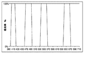
一部の実施形態では、光フィルタは、彩度に対する候補フィルタの効果を計算するために、候補フィルタのスペクトルプロフィールを使用して設計される。このようにすれば、フィルタにおける変更について、所望の結果の達成に対するそれらの有効性を繰り返しチェックすることができる。或いは、フィルタは、数値シミュレーションを通じて直接的に設計することができる。光フィルタの例及び比較例、並びにそれらの光フィルタが彩度に及ぼす効果が、本明細書で説明される。各事例では、各フィルタを通過する入力光の彩度が、フィルタをかけられていない同じ入力の彩度と比較される。可視スペクトル波長に対してプロットされた「吸収率%」のグラフは、光フィルタの例又は比較例のスペクトル吸
収率プロフィールを示している。可視スペクトル波長に対してプロットされた「彩度、C*、相対」の各グラフは、均一強度の30nm幅光刺激が波長依存性の光フィルタを通過した後における同刺激の相対彩度を、細めの曲線としてグラフ表示しており、各刺激の中心波長を、水平軸上の値によって表している。「彩度、C*、相対」の各グラフは、また、同じ30nm幅光刺激がその帯域幅内において波長依存性光フィルタと同じ平均比率で光を減衰させる中性フィルタを通過したときの、同刺激の相対彩度も示している。
In some embodiments, the light filter is designed using the spectral profile of the candidate filter to calculate the effect of the candidate filter on saturation. In this way, changes in the filter can be repeatedly checked for their effectiveness in achieving the desired result. Alternatively, the filter can be designed directly through numerical simulation. Examples of optical filters and comparative examples, and the effects of these optical filters on saturation are described herein. In each case, the saturation of the input light passing through each filter is compared with the saturation of the same input that is not filtered. The graph of “Absorptance%” plotted against the visible spectral wavelength shows the spectral absorptance profile of the optical filter example or the comparative example. The “Saturation, C * , Relative” graphs plotted against the visible spectral wavelength show the relative saturation of the same intensity after passing a 30 nm wide light stimulus of uniform intensity through a wavelength-dependent optical filter. The graph is displayed as a thin curve, and the center wavelength of each stimulus is represented by a value on the horizontal axis. The “Saturation, C * , Relative” graphs also show that when the same 30 nm wide light stimulus passes through a neutral filter that attenuates light within that bandwidth at the same average ratio as the wavelength dependent optical filter, The relative saturation of the stimulus is also shown.
フィルタ設計の目標の1つは、レンズの全体色の見え方を決定することであろう。一部の実施形態では、レンズから透過される全体光として知覚される色は、青銅色、琥珀色、紫色、灰色、又は別の色である。一部の事例では、消費者は、定量的に計算に入れることが困難な好みを有する。幾つかの事例では、レンズ色調整は、本開示で説明されるモデル内で達成することができる。フィルタ設計に対して全体色の調整が及ぼす影響は、適切なモデルを使用して計算することができる。一部の事例では、色調整は、求められる彩度特性の犠牲を幾らか伴って、又はほとんど伴わずに、又は全く伴わずに行うことができる。一部の実施形態では、レンズは、比較的低い彩度値を伴う全体色を有する。例えば、レンズは、60未満の彩度値を有することができる。このようなレンズに使用される彩度増強光フィルタは、より高い彩度値を伴う全体色を有するレンズに同じ光フィルタが使用されるときと比べて、少なくとも一部の色の精彩さを増加させることができる。 One goal of filter design would be to determine how the overall color of the lens looks. In some embodiments, the color perceived as total light transmitted from the lens is bronze, amber, purple, gray, or another color. In some cases, consumers have preferences that are difficult to quantitatively calculate. In some cases, lens color adjustment can be achieved within the model described in this disclosure. The effect of the overall color adjustment on the filter design can be calculated using an appropriate model. In some cases, color adjustments can be made with some or little or no sacrifice of the desired saturation characteristics. In some embodiments, the lens has an overall color with a relatively low saturation value. For example, the lens can have a saturation value of less than 60. Saturation-enhanced light filters used for such lenses increase the saturation of at least some colors compared to when the same light filter is used for lenses that have an overall color with higher saturation values Can be made.
光フィルタの一比較例は、図3、図4A、及び図4Bに示されるような特性を有する。図3は、光フィルタを有する比較例のレンズ、すなわちイリノイ州ピオリアのMaui Jim, Inc.から入手可能なLAGOON 189-02灰色レンズの吸収率プロフィールを示している。図4
Aは、図3に示された吸収率プロフィールを有するレンズの出力と、各刺激帯域内において図3のレンズと同じ平均比率で均一に光を減衰させるフィルタの出力との間における彩度の相違率を示しており、ここで、入力は、30nmの均一強度刺激であり、水平軸は、各刺激帯域の中心波長を示している。図4Aからわかるように、図3に示された吸収率プロフィールによって特徴付けられる比較例のレンズは、各30nm刺激に対して中性減衰を提供するフィルタと比べて、一部のスペクトル領域では幾らかの彩度増加を、そしてその他のスペクトル領域では幾らかの彩度減少を提供する。各刺激に対して中性減衰フィルタによって提供される平均減衰比率は、比較例のフィルタによって提供される平均減衰比率と同じである。本開示では、相対彩度プロフィールを計算するために、均一強度を有する特定帯域幅の光が使用された。フィルタの相対彩度プロフィールを示された図面では、1つの図面に示された相対彩度がその他の図面に示された相対彩度と比較可能であるように、別途明記されない限り本開示全体を通してスケールを一定に維持されている。一部の図面では、詳細を示すために及び一貫したスケールを維持するために、フィルタの彩度プロフィールが切り落とされている。
One comparative example of the optical filter has characteristics as shown in FIGS. 3, 4A, and 4B. FIG. 3 shows the absorptivity profile of a comparative lens with an optical filter, ie, a LAGOON 189-02 gray lens available from Maui Jim, Inc., Peoria, Illinois. FIG.
A is the chroma difference between the output of the lens having the absorptance profile shown in FIG. 3 and the output of the filter that attenuates light uniformly at the same average ratio as the lens of FIG. 3 within each stimulation band. Where the input is a 30 nm uniform intensity stimulus and the horizontal axis shows the center wavelength of each stimulus band. As can be seen from FIG. 4A, the comparative lens characterized by the absorptance profile shown in FIG. 3 is somewhat in some spectral regions compared to a filter that provides neutral attenuation for each 30 nm stimulus. Provides some saturation increase, and some saturation reduction in other spectral regions. The average attenuation ratio provided by the neutral attenuation filter for each stimulus is the same as the average attenuation ratio provided by the comparative filter. In this disclosure, a specific bandwidth of light with uniform intensity was used to calculate the relative saturation profile. Throughout the disclosure, unless otherwise specified, the drawings showing the relative saturation profiles of the filters are such that the relative saturation shown in one drawing is comparable to the relative saturation shown in the other drawings. The scale is kept constant. In some drawings, the saturation profile of the filter has been cut off to show details and to maintain a consistent scale.
一部の実施形態では、光フィルタは、可視スペクトルの青色領域から青緑色領域において彩度を増加させる又は最大化するように構成される。このような構成を有するフィルタは、図5に示されるように、約478nmに又は約480nmに中心がある吸収率ピークを有することができる。図5に示された吸収率ピークの半値全幅(FWHM)は、約20nmである。しかしながら、約10nm以上、約15nm以上、約20nm以上、約60nm以下、約50nm以下、約40nm以下、約10nmから約60nmまでの間、又は上記のその他の任意の値から値までの間の帯域幅などの、その他の吸収率ピーク幅を使用することができる。吸収率ピークの帯域幅は、FWHMに加えて又はFWHMに代わって任意の適切なやり方で測定することができる。例えば、吸収率ピークの帯域幅は、最大値の80%におけるピークの全幅を含むことができる。図6Aは、図5に示された吸収率プロフィールを有するフィルタの、波長の関数としての相対彩度を示している。繰り返しになるが、太めの黒線は、各30nm刺激帯域内において図5に示された光フィルタの各対応する帯域内と同じ積分光透過率を有する中性フィルタの彩度プロフィールに対応してい
る。図6Bは、図5の光フィルタの出力と、各刺激帯域内において図5の光フィルタと同じ平均比率で均一に光を減衰させるフィルタの出力との間における彩度の相違率を示しており、ここで、入力は、30nmの均一強度刺激であり、水平軸は、各刺激帯域の中心波長を示している。
In some embodiments, the light filter is configured to increase or maximize saturation from the blue region to the blue-green region of the visible spectrum. A filter having such a configuration can have an absorption peak centered at about 478 nm or about 480 nm, as shown in FIG. The full width at half maximum (FWHM) of the absorptance peak shown in FIG. 5 is about 20 nm. However, a band between about 10 nm or more, about 15 nm or more, about 20 nm or more, about 60 nm or less, about 50 nm or less, about 40 nm or less, between about 10 nm to about 60 nm, or between any other values above Other absorption peak widths, such as width, can be used. The bandwidth of the absorption peak can be measured in any suitable manner in addition to or in place of FWHM. For example, the bandwidth of the absorption peak can include the full width of the peak at 80% of the maximum value. FIG. 6A shows the relative saturation as a function of wavelength for the filter having the absorptance profile shown in FIG. Again, the thicker black lines correspond to the saturation profile of the neutral filter that has the same integrated light transmittance as in each corresponding band of the optical filter shown in FIG. 5 within each 30 nm stimulation band. Yes. 6B shows the saturation difference rate between the output of the optical filter of FIG. 5 and the output of the filter that attenuates light uniformly at the same average ratio as the optical filter of FIG. 5 within each stimulation band. Here, the input is a 30 nm uniform intensity stimulus, and the horizontal axis indicates the center wavelength of each stimulus band.
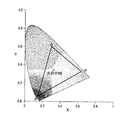
図5に示されるような吸収率プロフィールを有する光フィルタのCIE xy色度図が、図7に提供されている。色度図は、フィルタの色度、及びRGB色空間の全範囲を示している。本開示で提供される色度図の各々は、CIE光源D65を使用して計算された関連のフィルタ又はレンズの色度を示している。 A CIE xy chromaticity diagram of an optical filter having an absorptance profile as shown in FIG. 5 is provided in FIG. The chromaticity diagram shows the chromaticity of the filter and the entire range of the RGB color space. Each of the chromaticity diagrams provided in this disclosure shows the chromaticity of the associated filter or lens calculated using the CIE light source D65.
幾つかの実施形態では、光フィルタは、可視スペクトルの青色領域において彩度を増加させる又は最大化するように構成される。このような構成を有するフィルタは、中心波長が約453nm、約450nm、又は約445nmから約460nmまでの間にある吸収率ピークを提供することができる。吸収率ピークの帯域幅は、約10nm以上、約15nm以上、約20nm以上、又は別の適切な値であることができる。 In some embodiments, the light filter is configured to increase or maximize saturation in the blue region of the visible spectrum. A filter having such a configuration can provide an absorption peak with a center wavelength between about 453 nm, about 450 nm, or between about 445 nm and about 460 nm. The bandwidth of the absorptance peak can be about 10 nm or more, about 15 nm or more, about 20 nm or more, or another suitable value.
一部の実施形態では、光フィルタは、幾つかの色、多くの色、若しくは大半の色、又は少なくとも着用者の環境のなかでよく遭遇される多くの色にわたって彩度を増加させる又は最大化するように構成される。このような光フィルタは、複数の吸収率ピークを含むことができる。例えば、図8は、中心波長が約415nm、約478nm、約574nm、及び約715nmにある4つの吸収率ピークを含む光フィルタの一実施形態のスペクトル吸収率プロフィールを示している。この例のフィルタの相対彩度プロフィール及び色度図が、図9A、図9B、及び図10に示されている。図9Aに示された相対彩度プロフィールは、図8の光フィルタが、各30nm刺激帯域内において図8に示された光フィルタの各対応する帯域内と同じ積分光透過率を有する中性フィルタと比べて、少なくとも4つのスペクトル窓において彩度の大幅な増加を提供することを示している。図9Bは、図8の光フィルタの出力と、各刺激帯域内において図8の光フィルタと同じ平均比率で均一に光を減衰させるフィルタの出力との間における彩度の相違率を示しており、ここで、入力は、30nmの均一強度刺激であり、水平軸は、各刺激帯域の中心波長を示している。 In some embodiments, the light filter increases or maximizes saturation over several colors, many colors, or most colors, or at least many colors often encountered in the wearer's environment. Configured to do. Such an optical filter can include a plurality of absorption peak. For example, FIG. 8 shows the spectral absorptance profile of one embodiment of an optical filter that includes four absorptance peaks with center wavelengths at about 415 nm, about 478 nm, about 574 nm, and about 715 nm. The relative saturation profile and chromaticity diagram of this example filter are shown in FIGS. 9A, 9B, and 10. FIG. The relative saturation profile shown in FIG. 9A shows that the neutral filter in which the optical filter of FIG. 8 has the same integrated light transmittance in each 30 nm stimulation band as in each corresponding band of the optical filter shown in FIG. Compared to, it provides a significant increase in saturation in at least four spectral windows. FIG. 9B shows the saturation difference rate between the output of the optical filter of FIG. 8 and the output of the filter that uniformly attenuates light at the same average ratio as the optical filter of FIG. 8 within each stimulation band. Here, the input is a 30 nm uniform intensity stimulus, and the horizontal axis indicates the center wavelength of each stimulus band.
吸収率ピークの位置及び数として、その他にも多くのヴァリエーションが可能である。例えば、一部の実施形態は、約574nmにピークを提供するとともに約561nmに追加のピークを加えることによって、約558nmから約580nmまでの間において大幅に光を減衰させる。このような実施形態は、約555nm近くに中心を有する緑色領域において、大幅に大きい彩度を提供することができる。 Many other variations are possible in terms of the location and number of absorption peaks. For example, some embodiments significantly attenuate light between about 558 nm and about 580 nm by providing a peak at about 574 nm and adding an additional peak at about 561 nm. Such an embodiment can provide significantly greater saturation in the green region centered around 555 nm.
幾つかの実施形態では、光フィルタは、各吸収率ピークの帯域幅内における光の減衰程度を増加させることによって、可視スペクトルにおいて彩度を増加させる。吸収率ピークの帯域幅内における光の減衰の程度は、吸収率ピークのスペクトル帯域幅内における積分吸収率ピーク面積を吸収率ピークのスペクトル帯域幅で割ったものとして定義される「減衰係数」によって特徴付けることができる。減衰係数が1の吸収率ピークの一例は、方形波である。このような吸収率ピークは、そのスペクトル帯域内では実質的に全ての光を減衰させ、そのスペクトル帯域外では実質的に光を減衰させない。これに対して、減衰係数が0.5未満の吸収率ピークは、そのスペクトル帯域内では半分未満の光を減衰させ、そのスペクトル帯域外ではかなりの量の光を減衰させるだろう。減衰係数が厳密に1の吸収率ピークを有する光フィルタを作成することは不可能かもしれないが、減衰係数が1に近い吸収率ピークを有する光フィルタを設計することは可能である。 In some embodiments, the optical filter increases saturation in the visible spectrum by increasing the degree of light attenuation within the bandwidth of each absorption peak. The degree of light attenuation within the bandwidth of the absorptance peak is determined by the “attenuation coefficient” defined as the integral absorptivity peak area within the absorptive peak spectral bandwidth divided by the absorptive peak spectral bandwidth. Can be characterized. An example of an absorption peak with an attenuation coefficient of 1 is a square wave. Such an absorptance peak attenuates substantially all light within that spectral band and does not substantially attenuate light outside that spectral band. In contrast, an absorptivity peak with an attenuation coefficient less than 0.5 will attenuate less than half of the light within that spectral band and attenuate a significant amount of light outside that spectral band. Although it may not be possible to create an optical filter having an absorptivity peak with exactly 1 attenuation coefficient, it is possible to design an optical filter with an absorptivity peak close to 1.
幾つかの実施形態では、光フィルタは、減衰係数が1に近い1つ又は2つ以上の吸収率ピークを有するように構成される。その他にも、多くの構成が可能である。一部の実施形
態では、光フィルタは、減衰係数が約0.8以上、約0.9以上、約0.95以上、約0.98以上、約0.8から約0.99までの間、約0.8以上で且つ1未満、又は上記のその他の任意の値から値までの間である1つ又は2つ以上の吸収率ピークを有する。まとめて、減衰係数に対する上記の制限は、「減衰係数基準」と呼ぶことができる。幾つかの実施形態では、光フィルタにおける各吸収率ピークの減衰係数は、減衰係数基準の1つ又は2つ以上を満たしている。一部の実施形態では、光フィルタにおける或る特定の吸収率閾値を超える最大吸収率を有する各吸収率ピークの減衰係数は、減衰係数基準の1つ又は2つ以上を満たしている。吸収率閾値は、約0.5、約0.7、約0.9、約1、0.5から1までの間、又は別の値であることができる。本明細書では、光フィルタに言及して幾つかのスペクトル特徴が説明されているが、これらのスペクトル特徴の各々は、別途明記されない限り、光フィルタを内包したレンズのスペクトルプロフィールにも等しく適用可能であることが理解される。
In some embodiments, the optical filter is configured to have one or more absorption peaks with an attenuation coefficient close to unity. Many other configurations are possible. In some embodiments, the optical filter has an attenuation coefficient of about 0.8 or more, about 0.9 or more, about 0.95 or more, about 0.98 or more, between about 0.8 to about 0.99. , Having one or more absorption peaks that are greater than or equal to about 0.8 and less than 1, or between any other values above. Collectively, the above limitations on the damping factor can be referred to as the “damping factor criterion”. In some embodiments, the attenuation coefficient of each absorption peak in the optical filter meets one or more of the attenuation coefficient criteria. In some embodiments, the attenuation coefficient of each absorptance peak having a maximum absorptance that exceeds a certain absorptance threshold in the optical filter meets one or more of the attenuation coefficient criteria. The absorption threshold can be between about 0.5, about 0.7, about 0.9, about 1, 0.5 to 1, or another value. Although several spectral features are described herein with reference to an optical filter, each of these spectral features is equally applicable to the spectral profile of a lens containing an optical filter, unless otherwise specified. It is understood that
一部の実施形態では、光フィルタは、約0.95以上の減衰係数を各々が有する4つのスペクトル帯域の各々において吸収率ピークを有する。物理的な世界では、単色光を観測することは稀であるので、自然の世界で知覚されるスペクトル色の全体的多様性を大幅に損なうことなく幾らかの狭帯域の光を完全に又はほぼ完全に遮ることが可能である。言い換えると、光フィルタは、実質的に視覚情報を喪失することなく日常の視覚に用いることができる。これらの属性を有する光フィルタの一例のスペクトル吸収率プロフィールが、図11に示されている。同じ光フィルタの相対彩度プロフィール及び色度図が、図12A、図12B、及び図13に示されている。図12Aに示された相対彩度プロフィールは、太めの黒線で示された、各30nm刺激帯域内において図8に示された光フィルタの各対応する帯域内と同じ積分光透過率を有する中性フィルタの彩度プロフィールと、細めの黒線で示され、中性フィルタプロフィールよりも概ね高い、図8に示された波長依存性フィルタの彩度プロフィールとを含む。図12Bは、図11の光フィルタの出力と、各刺激帯域内において図11の光フィルタと同じ平均比率で均一に光を減衰させるフィルタの出力との間における彩度の相違率を示しており、ここで、入力は、30nmの均一強度刺激であり、水平軸は、各刺激帯域の中心波長を示している。 In some embodiments, the optical filter has an absorptivity peak in each of the four spectral bands, each having an attenuation coefficient of about 0.95 or greater. In the physical world, monochromatic light is rarely observed, so some narrowband light can be completely or almost completely lost without significantly compromising the overall diversity of spectral colors perceived in the natural world. It can be completely blocked. In other words, the light filter can be used for everyday vision without substantial loss of visual information. An example spectral absorptance profile of an optical filter having these attributes is shown in FIG. Relative saturation profiles and chromaticity diagrams for the same light filter are shown in FIGS. 12A, 12B, and 13. The relative saturation profile shown in FIG. 12A is a medium with the same integrated light transmittance as in each corresponding band of the optical filter shown in FIG. 8 within each 30 nm stimulation band, indicated by a thick black line. And the saturation profile of the wavelength-dependent filter shown in FIG. 8, which is indicated by a thin black line and is generally higher than the neutral filter profile. FIG. 12B shows the saturation difference rate between the output of the optical filter of FIG. 11 and the output of the filter that uniformly attenuates light at the same average ratio as that of the optical filter of FIG. 11 within each stimulation band. Here, the input is a 30 nm uniform intensity stimulus, and the horizontal axis indicates the center wavelength of each stimulus band.
一部の実施形態では、光フィルタは、帯域幅を少なくとも部分的に彩度増強窓内に有する1つ又は2つ以上の吸収率ピークを有する。彩度増強窓の幅は、約22nmから約45nmまでの間、約20nmから約50nmまでの間、約20nm以上、約15nm以上、又は別の適切な帯域幅範囲であることができる。幾つかの実施形態では、光フィルタは、吸収率閾値以上の減衰係数を有する全ての吸収率ピークが、彩度増強窓内に帯域幅を有するように構成される。例えば、吸収率ピークの各々の帯域幅は、約10nm以上、約15nm以上、約20nm以上、約22nm以上、約60nm以下、約50nm以下、約40nm以下、約10nmから約60nmまでの間、約20nmから約45nmまでの間、又は上記のその他の任意の値から値までの間であることができる。 In some embodiments, the optical filter has one or more absorption peaks that have bandwidth at least partially within the saturation enhancement window. The width of the saturation enhancement window can be between about 22 nm and about 45 nm, between about 20 nm and about 50 nm, about 20 nm or more, about 15 nm or more, or another suitable bandwidth range. In some embodiments, the optical filter is configured such that all absorptivity peaks having an attenuation coefficient greater than or equal to the absorptivity threshold have a bandwidth within the saturation enhancement window. For example, the bandwidth of each of the absorption peaks may be about 10 nm or more, about 15 nm or more, about 20 nm or more, about 22 nm or more, about 60 nm or less, about 50 nm or less, about 40 nm or less, between about 10 nm to about 60 nm, about It can be between 20 nm and about 45 nm, or between any other values mentioned above.
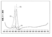
帯域幅(例えばFWHM値)及び吸収率ピークのサイド傾斜の変動は、彩度に対して著しい影響を有する可能性がある。総じて、FWHMの増加及び/又は彩度増強ピークの傾斜の増加は、彩度の増加を伴い、彩度下降ピークの場合は、その逆もまた然りである。図14及び図16には、FWHM及び吸収率ピークの傾斜が別々に変動されたときの、光フィルタの例が示されている。彩度に対するこれらの変動の影響は、付随する図15A〜15B及び図17A〜17Bの彩度プロフィールに示されている。図14では、3つの異なるフィルタF1、F2、及びF3について、478nmを中心とした吸収率ピークの重なりが示されている。これらの吸収率ピークは、等しいサイド傾斜と、異なるFWHM値とを有し、フィルタF1が最低のFWHM値を、フィルタF3が最高のFWHM値を有する。図15Aにおける相対彩度プロフィールは、図14に示されたフィルタF1、F2、及びF3が彩度に対して及ぼす影響を示している。各グラフにおいて、フィルタF1、F2
、及びF3の各々の吸収率及び彩度プロフィールは、対応する同じ線様式で示されており、図15Aでは、中性フィルタが、太線で含まれている。図15Bは、図14の3つの光フィルタF1、F2、及びF3の出力と、各刺激帯域内において図14の光フィルタと同じ平均比率で均一に光を減衰させるフィルタの出力との間における彩度の相違率を示しており、ここで、入力は、30nmの均一強度刺激であり、水平軸は、各刺激帯域の中心波長を示している。
Variations in bandwidth (eg, FWHM value) and side slope of the absorption peak can have a significant effect on saturation. Overall, an increase in FWHM and / or an increase in the slope of the saturation enhancement peak is accompanied by an increase in saturation, and vice versa for the saturation decline peak. FIGS. 14 and 16 show examples of optical filters when the slopes of the FWHM and the absorption peak are changed separately. The effect of these variations on saturation is shown in the accompanying FIGS. 15A-15B and 17A-17B saturation profiles. FIG. 14 shows the absorption peak overlap centered on 478 nm for three different filters F1, F2 and F3. These absorption peaks have equal side slopes and different FWHM values, with filter F1 having the lowest FWHM value and filter F3 having the highest FWHM value. The relative saturation profile in FIG. 15A shows the effect that the filters F1, F2, and F3 shown in FIG. 14 have on saturation. In each graph, filters F1 and F2
, And F3's respective absorptance and saturation profiles are shown in the same corresponding line style, and in FIG. 15A, a neutral filter is included with a bold line. FIG. 15B shows the chroma between the output of the three optical filters F1, F2, and F3 of FIG. 14 and the output of the filter that attenuates light uniformly at the same average ratio as the optical filter of FIG. 14 within each stimulation band. The degree of dissimilarity is shown, where the input is a 30 nm uniform intensity stimulus and the horizontal axis indicates the center wavelength of each stimulus band.
図16は、等しいFWHMと、異なる傾斜とを有する、478nmを中心とした3つの吸収率ピークの重なりを示している。図17Aは、図16に示されたフィルタF4、F5、及びF6が彩度に対して及ぼす影響を示しており、ここでもやはり、太い実線で中性フィルタが含まれている。図17Bは、図16の3つの光フィルタF4、F5、及びF6の出力と、各刺激帯域内において図16の光フィルタと同じ平均比率で均一に光を減衰させるフィルタの出力との間における彩度の相違率を示しており、ここで、入力は、30nmの均一強度刺激であり、水平軸は、各刺激帯域の中心波長を示している。 FIG. 16 shows the overlap of three absorption peaks centered at 478 nm with equal FWHM and different slopes. FIG. 17A shows the effect of the filters F4, F5, and F6 shown in FIG. 16 on the saturation, again including a neutral filter with a thick solid line. FIG. 17B shows the chroma between the outputs of the three optical filters F4, F5, and F6 of FIG. 16 and the output of the filter that attenuates light uniformly at the same average ratio as the optical filter of FIG. 16 within each stimulation band. The degree of dissimilarity is shown, where the input is a 30 nm uniform intensity stimulus and the horizontal axis indicates the center wavelength of each stimulus band.
図11に示された光フィルタに戻り、415nm及び715nmを中心とした外側2つの吸収率ピークは、概して可視スペクトルの外縁における光波長に影響を及ぼす外側傾斜(すなわち、415nmピークの下限及び715nmピークの上限)を有する。一部の実施形態では、これらのピークの吸収率プロフィールは、可視範囲の主要部分だと見なすことができるおおよそ400nmから700nmまでの範囲の外側の波長の光を大幅に、大半に、又はほぼ完全に減衰させるように変化させることができる。これらの属性を有する光フィルタの一例のスペクトル吸収率プロフィールが、図18に示されている。同じ光フィルタの相対彩度プロフィール及び色度図が、図19A、図19B、及び図20に示されている。図19Bは、図18の光フィルタの出力と、各刺激帯域内において図18の光フィルタと同じ平均比率で均一に光を減衰させるフィルタの出力との間における彩度の相違率を示しており、ここで、入力は、30nmの均一強度刺激であり、水平軸は、各刺激帯域の中心波長を示している。 Returning to the optical filter shown in FIG. 11, the two outer absorption peaks centered at 415 nm and 715 nm generally have an outer slope that affects the light wavelength at the outer edge of the visible spectrum (ie, the lower limit of the 415 nm peak and the 715 nm peak). Upper limit). In some embodiments, the absorption profile of these peaks is significantly, mostly, or nearly complete with light at wavelengths outside the range of approximately 400 nm to 700 nm, which can be considered a major portion of the visible range. Can be changed to attenuate. An example spectral absorptance profile of an optical filter having these attributes is shown in FIG. Relative saturation profiles and chromaticity diagrams for the same light filter are shown in FIGS. 19A, 19B, and 20. FIG. FIG. 19B shows the saturation difference rate between the output of the optical filter of FIG. 18 and the output of the filter that uniformly attenuates light at the same average ratio as the optical filter of FIG. 18 within each stimulation band. Here, the input is a 30 nm uniform intensity stimulus, and the horizontal axis indicates the center wavelength of each stimulus band.
本明細書で開示される技術にしたがって彩度を制御すれば、1つ又は2つ以上の色帯域ではあまり精彩さを望まれないような状況において、それらの帯域の彩度を減少させることもできる。一部の実施形態では、光フィルタは、1つ又は2つ以上の帯域では彩度を減少させてその他の帯域では彩度を増加させるように構成することができる。例えば、鴨狩の用途用に設計されたアイウェアは、青色の背景の彩度を下げるとともに飛んでいる鴨の緑色及び茶色の羽の彩度を増加させるように構成された光フィルタを有する1枚又は2枚以上のレンズを含むことができる。より一般的に言うと、光フィルタは、特定の背景(例えば、地面、空、競技用のグラウンド若しくはコート、又はそれらの組み合わせなど)に関連付けられた1つ又は2つ以上のスペクトル領域では相対的に下げられた彩度を提供し、特定の前景又は物体(例えばボール)に関連付けられた1つ又は2つ以上のスペクトル領域では相対的に高い彩度を提供することによって、活動に固有に設計することができる。或いは、光フィルタは、背景のスペクトル領域及び物体のスペクトル領域の両方で彩度の増加を提供することによって、活動に固有の構成を有することができる。
Controlling the saturation according to the techniques disclosed herein can also reduce the saturation of those bands in situations where one or more of the color bands does not require so much saturation. it can. In some embodiments, the optical filter can be configured to decrease saturation in one or more bands and increase saturation in other bands. For example, eyewear designed for duck hunting uses light filters configured to reduce the saturation of a blue background and increase the saturation of green and brown feathers of a flying
移動物体を識別及び認識する能力は、一般に、「動体視力」と呼ばれる。彩度の増加は、一般に、より高い色コントラストに関連付けられるので、移動物体のスペクトル領域における彩度の増加は、この質を改善することを期待される。更に、特定の色の強調又は非強調が、動体視力を更に改善することができる。動体視力を高めるように構成された光フィルタの一例のスペクトル吸収率プロフィールが、図21に示されている。示された光フィルタは、緑色から橙色のスペクトル領域では高い彩度を、青色のスペクトル領域では相対的に低い彩度を提供するように構成される。同じ光フィルタの相対彩度プロフィール及び色度図が、図22A、図22B、及び図23に示されている。図22Bは、図21の光
フィルタの出力と、各刺激帯域内において図21の光フィルタと同じ平均比率で均一に光を減衰させるフィルタの出力との間における彩度の相違率を示しており、ここで、入力は、30nmの均一強度刺激であり、水平軸は、各刺激帯域の中心波長を示している。
The ability to identify and recognize moving objects is commonly referred to as “moving vision”. Since an increase in saturation is generally associated with higher color contrast, an increase in saturation in the spectral region of the moving object is expected to improve this quality. Furthermore, enhancement or de-emphasis of certain colors can further improve moving vision. An example spectral absorptance profile of an optical filter configured to enhance dynamic visual acuity is shown in FIG. The light filter shown is configured to provide high saturation in the green to orange spectral region and relatively low saturation in the blue spectral region. Relative saturation profiles and chromaticity diagrams for the same light filter are shown in FIGS. 22A, 22B, and 23. FIG. FIG. 22B shows the saturation difference rate between the output of the optical filter of FIG. 21 and the output of the filter that attenuates light uniformly at the same average ratio as the optical filter of FIG. 21 within each stimulation band. Here, the input is a 30 nm uniform intensity stimulus, and the horizontal axis indicates the center wavelength of each stimulus band.
一部の実施形態では、光フィルタは、可視スペクトルにわたる視感度の変動を計算に入れるように構成される。視感度を計算に入れることによって、フィルタは、様々な色帯域に対して人間の眼が有する異なる波長間における相対感度の差を補償することができる。Stockman and Sharpeによる錐体感度データとの間に一貫性を有する可視スペクトルにお
ける視感度が、図24に示されている。
In some embodiments, the light filter is configured to account for variations in visibility across the visible spectrum. By taking the visibility into account, the filter can compensate for the difference in relative sensitivity between different wavelengths of the human eye for various color bands. Visibility in the visible spectrum consistent with the cone sensitivity data by Stockman and Sharpe is shown in FIG.
幾つかの実施形態では、光フィルタは、人間の眼が最も高感度である赤色波長における彩度を選択的に増加させるように構成される。例えば、赤色帯域は、約625nmから約700nmまでの間にわたるスペクトル範囲として言い表すことができる。図24に示された視感度関数を見ると、眼は、約625nmから660nmまでの間の赤色光に対し、それよりも長い波長よりも大幅に高感度であることが明らかである。したがって、この構成を有する光フィルタのスペクトル吸収率プロフィールが、図25に示されている。光フィルタは、約715nmを中心としたピークの代わりに約658nmを中心とした赤色帯域に代替のピークを有することを除き、図11に示されたものと同じプロフィールを有する。結果は、655nm以下の赤色帯域にかけては彩度が増加し、それに伴って、眼があまり高感度ではない600nmより上の赤色の彩度は減少した。同じ光フィルタの相対彩度プロフィール及び色度図が、図26A、図26B、及び図27に示されている。図26Bは、図25の光フィルタの出力と、各刺激帯域内において図25の光フィルタと同じ平均比率で均一に光を減衰させるフィルタの出力との間における彩度の相違率を示しており、ここで、入力は、30nmの均一強度刺激であり、水平軸は、各刺激帯域の中心波長を示している。 In some embodiments, the light filter is configured to selectively increase saturation at red wavelengths where the human eye is most sensitive. For example, the red band can be expressed as a spectral range extending between about 625 nm to about 700 nm. Looking at the visibility function shown in FIG. 24, it is clear that the eye is significantly more sensitive to red light between about 625 nm and 660 nm than longer wavelengths. Therefore, the spectral absorptance profile of the optical filter having this configuration is shown in FIG. The optical filter has the same profile as shown in FIG. 11 except that it has an alternative peak in the red band centered at about 658 nm instead of a peak centered at about 715 nm. The result showed that the saturation increased over the red band below 655 nm, with a concomitant decrease in the red saturation above 600 nm where the eye was not very sensitive. The relative saturation profile and chromaticity diagram of the same light filter are shown in FIGS. 26A, 26B, and 27. FIG. FIG. 26B shows the saturation difference rate between the output of the optical filter of FIG. 25 and the output of the filter that attenuates light uniformly at the same average ratio as the optical filter of FIG. 25 within each stimulation band. Here, the input is a 30 nm uniform intensity stimulus, and the horizontal axis indicates the center wavelength of each stimulus band.
また、約553nm、約561nm、又は約550nmから約570nmまでの間の波長を中心とした吸収率ピークを使用して、緑色範囲の半ばにおける波長の彩度を増加させることができる。このようなフィルタは、黄色の彩度を減少させることもできるので、黄色の背景を背にして見る緑色物体の識別によって恩恵を得られる活動に使用することができる。緑色スペクトル範囲の半ばにおいて彩度を増加させる光フィルタのスペクトル吸収率プロフィールが、図28に示されている。同じ光フィルタの相対彩度プロフィール及び色度図が、図29A、図29B、及び図30にそれぞれ示されている。図29Bは、図28の光フィルタの出力と、各刺激帯域内において図28の光フィルタと同じ平均比率で均一に光を減衰させるフィルタの出力との間における彩度の相違率を示しており、ここで、入力は、30nmの均一強度刺激であり、水平軸は、各刺激帯域の中心波長を示している。 Also, absorption peaks centered around wavelengths between about 553 nm, about 561 nm, or about 550 nm to about 570 nm can be used to increase the saturation of the wavelength in the middle of the green range. Such a filter can also reduce yellow saturation, so it can be used for activities that can benefit from the identification of green objects viewed against a yellow background. The spectral absorptance profile of an optical filter that increases saturation in the middle of the green spectral range is shown in FIG. The relative saturation profile and chromaticity diagram for the same light filter are shown in FIGS. 29A, 29B, and 30, respectively. FIG. 29B shows the saturation difference rate between the output of the optical filter of FIG. 28 and the output of the filter that uniformly attenuates light at the same average ratio as the optical filter of FIG. 28 within each stimulation band. Here, the input is a 30 nm uniform intensity stimulus, and the horizontal axis indicates the center wavelength of each stimulus band.
上で示されたフィルタプロフィールを作成するためには、参照によってその内容全体を本明細書に組み込まれるとともに本明細書の一部を構成している米国特許第5,054,902号に記載されるように、誘電体スタック、多層干渉性コーティング、希土類酸化物添加剤、有機染料、又は複数偏光フィルタの組み合わせの使用を通じてなどの、様々なアプローチを適用することができる。別の適切な作成技術又は複数技術の組み合わせもまた、使用することができる。 To create the filter profile shown above, it is described in US Pat. No. 5,054,902, the entire contents of which are hereby incorporated by reference and made a part hereof. As such, various approaches can be applied, such as through the use of dielectric stacks, multilayer interference coatings, rare earth oxide additives, organic dyes, or combinations of multiple polarizing filters. Other suitable creation techniques or combinations of techniques can also be used.
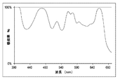
幾つかの実施形態では、光フィルタは、比較的高い減衰係数を有する吸収率ピークを提供する1つ又は2つ以上の有機染料を含む。例えば、一部の実施形態では、レンズは、オハイオ州のデートンにあるExcitonによって供給される有機染料を組み入れた光フィルタ
を有する。Excitonによって供給される少なくとも幾つかの有機染料は、それらの吸収率
ピークのおおよその中心波長にしたがって命名されている。ExcitonのABS 407染料、ABS
473染料、ABS 574染料、及びABS 659染料を組み入れた光フィルタを有する非偏光ポリカ
ーボネートレンズのおおよそのスペクトル吸収率プロフィールが、図31に示されている。光フィルタの有機染料配合設計は、約407nm、約473nm、約574nm、及び約659nmに吸収率ピークを提供する。このレンズの相対彩度プロフィール及び色度図が、図32A、図32B、及び図33にそれぞれ示されている。図32Bは、図31の光フィルタの出力と、各刺激帯域内において図31の光フィルタと同じ平均比率で均一に光を減衰させるフィルタの出力との間における彩度の相違率を示しており、ここで、入力は、30nmの均一強度刺激であり、水平軸は、各刺激帯域の中心波長を示している。
In some embodiments, the optical filter includes one or more organic dyes that provide an absorptance peak having a relatively high attenuation coefficient. For example, in some embodiments, the lens has an optical filter that incorporates an organic dye supplied by Exciton in Dayton, Ohio. At least some organic dyes supplied by Exciton are named according to the approximate center wavelength of their absorption peak. Exciton ABS 407 dye, ABS
The approximate spectral absorptance profile of an unpolarized polycarbonate lens with an optical filter incorporating 473 dye, ABS 574 dye, and ABS 659 dye is shown in FIG. The optical dye organic dye formulation design provides absorption peaks at about 407 nm, about 473 nm, about 574 nm, and about 659 nm. The relative saturation profile and chromaticity diagram of this lens are shown in FIGS. 32A, 32B, and 33, respectively. FIG. 32B shows the saturation difference rate between the output of the optical filter of FIG. 31 and the output of the filter that attenuates light uniformly at the same average ratio as the optical filter of FIG. 31 within each stimulation band. Here, the input is a 30 nm uniform intensity stimulus, and the horizontal axis indicates the center wavelength of each stimulus band.
一部の実施形態は、前の段落で説明された実施形態と同様であるが、ただし、Exciton
のABS 659染料の代わりにExcitonのABS 647染料を使用し、647nmに位置する赤色吸
収率ピークを含んでいる。このような実施形態では、人間の眼の感度のピークのより近くに位置する、より高視感度の赤い色彩の彩度が増加される。この構成の光フィルタを有する非偏光ポリカーボネートレンズのスペクトル吸収率プロフィールが、図34に示されている。プロフィールは、約407nm、473nm、574nm、及び647nmに吸収率ピークを含んでいる。このレンズの相対彩度プロフィール及び色度図が、図35A、図35B、及び図36にそれぞれ示されている。図35Bは、図34の光フィルタの出力と、各刺激帯域内において図34の光フィルタと同じ平均比率で均一に光を減衰させるフィルタの出力との間における彩度の相違率を示しており、ここで、入力は、30nmの均一強度刺激であり、水平軸は、各刺激帯域の中心波長を示している。
Some embodiments are similar to the embodiments described in the previous paragraph, except that Exciton
Exciton's ABS 647 dye is used in place of the ABS 659 dye and contains a red absorbance peak located at 647 nm. In such an embodiment, the saturation of the higher visibility red color located closer to the sensitivity peak of the human eye is increased. The spectral absorptance profile of a non-polarized polycarbonate lens having an optical filter of this configuration is shown in FIG. The profile includes absorption peaks at about 407 nm, 473 nm, 574 nm, and 647 nm. The relative saturation profile and chromaticity diagram of this lens are shown in FIGS. 35A, 35B, and 36, respectively. FIG. 35B shows the saturation difference rate between the output of the optical filter of FIG. 34 and the output of the filter that uniformly attenuates light at the same average ratio as the optical filter of FIG. 34 within each stimulation band. Here, the input is a 30 nm uniform intensity stimulus, and the horizontal axis indicates the center wavelength of each stimulus band.
一部の実施形態では、別の光フィルタが、幾つかの色、多くの色、若しくは大半の色、又は少なくとも着用者の環境のなかでよく遭遇される多くの色にわたって彩度を増加させる又は最大化するように構成される。このような光フィルタは、複数の吸収率ピークを含むことができる。複数の吸収率ピークは、約415nmから約455nmまでの間、約478nm、約555nmから約580nmまでの間、及び約660nmに中心波長を有する吸収率ピークを含むことができる。複数の吸収率ピークのFWHM値は、約20nmから約50nmまでの間の値、約20nmよりも大きい値、約22nm、約45nm、別の適切な値、又は複数値の組み合わせであることができる。一部の実施形態では、約555nmから約580nmまでの間に中心波長を有する吸収率ピークのFWHM値は、スペクトルプロフィールのなかの少なくとも一部のその他の吸収率ピークのFWHM値の約2倍である。この段落で説明される実施形態が反映される吸収率ピークを有するフィルタの一例のおおよそのスペクトル吸収率プロフィールが、図37に示されている。この例のフィルタは、約490nmに吸収率の急落を有し、これは、491nmにおける、並びに491nm近隣(例えば、491nm近辺及び約491nm以上の波長帯域)の広帯域にわたる(例えば、帯域幅にして約20nm以上のスペクトル帯域に及ぶ)光の大幅な透過を可能にする。 In some embodiments, another light filter increases saturation over several colors, many colors, or most colors, or at least many colors often encountered in the wearer's environment, or Configured to maximize. Such an optical filter can include a plurality of absorption peak. The plurality of absorptance peaks can include absorptance peaks having a center wavelength between about 415 nm and about 455 nm, between about 478 nm, between about 555 nm and about 580 nm, and at about 660 nm. The FWHM value of the plurality of absorption peaks can be a value between about 20 nm to about 50 nm, a value greater than about 20 nm, about 22 nm, about 45 nm, another suitable value, or a combination of multiple values. . In some embodiments, the FWHM value of an absorption peak having a central wavelength between about 555 nm and about 580 nm is about twice the FWHM value of at least some other absorption peak in the spectral profile. is there. An approximate spectral absorptance profile of an example of a filter having an absorptance peak that reflects the embodiments described in this paragraph is shown in FIG. The filter of this example has a sharp drop in absorption at about 490 nm, which spans a wide band (eg, about 491 nm and near 491 nm (eg, near 491 nm and above about 491 nm). Allows significant transmission of light (which covers a spectral band of 20 nm or more).
図37の吸収率プロフィールを有するフィルタの相対彩度プロフィールが、図38Aに示されている。より大きな彩度変動を示すために、図38Aの彩度プロフィールは、本開示におけるその他の彩度プロフィールとは異なる縦軸スケールで示されている。この例のフィルタは、約410nmから約460nmまでの間、約465nmから約475nmまでの間、約480nmから約500nmまでの間、約540nmから約565nmまでの間、約570nmから約600nmまでの間、及び約630nmから約660nmまでの間のスペクトル帯域などの、複数のスペクトル帯域において、フィルタを経ていない事例と比べて相対彩度の大幅な増加を生じる。図38Bは、図37の光フィルタの出力と、各刺激帯域内において図37の光フィルタと同じ平均比率で均一に光を減衰させるフィルタの出力との間における彩度の相違率を示しており、ここで、入力は、30nmの均一強度刺激であり、水平軸は、各刺激帯域の中心波長を示している。この例のフィルタの色度図が、図39に示されている。 The relative saturation profile of the filter having the absorptance profile of FIG. 37 is shown in FIG. 38A. In order to show greater saturation variation, the saturation profile of FIG. 38A is shown on a different vertical scale than the other saturation profiles in this disclosure. The filter of this example is between about 410 nm and about 460 nm, between about 465 nm and about 475 nm, between about 480 nm and about 500 nm, between about 540 nm and about 565 nm, between about 570 nm and about 600 nm. And in a plurality of spectral bands, such as a spectral band between about 630 nm and about 660 nm, results in a significant increase in relative saturation compared to an unfiltered case. FIG. 38B shows the saturation difference rate between the output of the optical filter of FIG. 37 and the output of the filter that uniformly attenuates light at the same average ratio as the optical filter of FIG. 37 within each stimulation band. Here, the input is a 30 nm uniform intensity stimulus, and the horizontal axis indicates the center wavelength of each stimulus band. A chromaticity diagram of this example filter is shown in FIG.
一部の実施形態では、単一の吸収率ピーク、又は互いに極めて接近している複数の吸収率ピークを形成するために、2つ又は3つ以上の染料を使用することができる。例えば、約555nmから約580nmまでの間に中心波長が位置している吸収率ピークは、約561nm及び約574nmに中心波長を有する2つの染料を使用して作成することができる。別の実施形態では、約555nmから約580nmまでの間に中心波長が位置している吸収率ピークを、約556nm及び約574nmに中心波長を有する2つの染料を使用して作成することができる。各染料は、FWHM値が約30nm未満の吸収率ピークを個々に形成することができるが、1つの光フィルタに複数の染料が使用されるときは、複数の吸収率ピークが組み合わさって、約45nmである又は約40nmよりも大きいFWHM値を有する単一の吸収率ピークを形成することができる。 In some embodiments, two or more dyes can be used to form a single absorption peak or multiple absorption peaks that are very close to each other. For example, an absorption peak with a center wavelength located between about 555 nm and about 580 nm can be created using two dyes having center wavelengths at about 561 nm and about 574 nm. In another embodiment, an absorption peak with a central wavelength located between about 555 nm and about 580 nm can be created using two dyes having central wavelengths at about 556 nm and about 574 nm. Each dye can individually form an absorption peak with a FWHM value of less than about 30 nm, but when multiple dyes are used in one optical filter, the multiple absorption peaks combine to give A single absorption peak can be formed having a FWHM value of 45 nm or greater than about 40 nm.
有機染料を組み入れたフィルタは、任意の適切な技術を使用して作成することができる。一部の実施形態では、1つ又は2つ以上のスペクトル領域における透過率を約1%以下に下げるために、十分な量の1つ又は2つ以上の有機染料が使用される。厚さが1.75mmのポリカーボネートレンズにおいて1%未満のピーク透過率を達成するために、1バッチのポリカーボネート樹脂に染料を混ぜ込むことができる。もし、混合物が、5lbsのポリカーボネート樹脂を含むならば、図31に示された吸収率プロフィールに関連付けられた光フィルタのために、以下のように、Exciton染料を装填することができる。すな
わち、ABS 407を44mg、ABS 473を122mg、ABS 574を117mg、及びABS 659を63mgである。上記の例では、ポリカーボネートにおける染料装填比を、以下のように一般化することができる。すなわち、合計1000単位の染料のうち、フィルタは、紫色吸収染料を約130単位、青色吸収染料を約350単位、緑色吸収染料を約340単位、及び深紅色吸収染料を約180単位含むことができる。
Filters incorporating organic dyes can be made using any suitable technique. In some embodiments, a sufficient amount of one or more organic dyes is used to reduce the transmission in one or more spectral regions to about 1% or less. In order to achieve a peak transmission of less than 1% in a 1.75 mm thick polycarbonate lens, the dye can be incorporated into a batch of polycarbonate resin. If the mixture contains 5 lbs of polycarbonate resin, Exciton dye can be loaded for the optical filter associated with the absorption profile shown in FIG. 31 as follows. That is, ABS 407 is 44 mg, ABS 473 is 122 mg, ABS 574 is 117 mg, and ABS 659 is 63 mg. In the above example, the dye loading ratio in the polycarbonate can be generalized as follows. That is, out of a total of 1000 units, the filter may include about 130 units of purple absorbing dye, about 350 units of blue absorbing dye, about 340 units of green absorbing dye, and about 180 units of crimson absorbing dye. .
同じ量のポリカーボネート樹脂において、図34に示された吸収率プロフィールに関連付けられた光フィルタのために、以下のように、Exciton染料を装填することができる。
すなわち、ABS 407を44mg、ABS 473を122mg、ABS 574を117mg、及びABS 647を41mgである。上記の例では、ポリカーボネートにおける染料装填比を、以下のように一般化することができる。すなわち、合計995単位の染料のうち、フィルタは、紫色吸収染料を約135単位、青色吸収染料を約375単位、緑色吸収染料を約360単位、及び赤色吸収染料を約125単位含むことができる。幾つかの実施形態では、レンズは、鋳込みプロセス、成形プロセス、又はその他の任意の適切なプロセスによって、樹脂と染料の混合物から形成することができる。
For the same amount of polycarbonate resin, the Exciton dye can be loaded for the optical filter associated with the absorptivity profile shown in FIG. 34 as follows.
That is, ABS 407 is 44 mg, ABS 473 is 122 mg, ABS 574 is 117 mg, and ABS 647 is 41 mg. In the above example, the dye loading ratio in the polycarbonate can be generalized as follows. That is, of the total 995 units of dye, the filter may include about 135 units of purple absorbing dye, about 375 units of blue absorbing dye, about 360 units of green absorbing dye, and about 125 units of red absorbing dye. In some embodiments, the lens may be formed from a resin and dye mixture by a casting process, a molding process, or any other suitable process.
やはり大幅な彩度増加をもたらすことができるその他のプラスチック用染料も存在する。例えば、ニューヨーク州のビンガムトンにあるCrysta-Lyn Chemical Companyは、40
2nmに吸収率ピークを有するDLS 402A染料を供給している。一部の実施形態では、DLS 402A染料は、上述された配合設計において、Exciton ABS 407染料の代わりに使用するこ
とができる。Crysta-Lynは、また、461nmに吸収率ピークを提供するDLS 461B染料も供給している。DLS 461B染料は、上述された配合設計において、Exciton ABS 473染料の
代わりに使用することができる。これらの配合設計では、Exciton ABS 574染料の代わり
にCrysta-Lyn DLS 564B染料を使用することができ、一方で、Exciton ABS 659染料の代わりにはCrysta-Lyn DLS 654Bを使用することができる。一部の実施形態では、1つ又は2
つ以上のレンズ構成要素に染料を組み入れることができ、どのレンズ構成要素が染料を含むかに関する判断は、各個別の染料の、安定度又は性能係数などの特性に基づくことができる。
There are other plastic dyes that can also result in significant saturation increases. For example, Crysta-Lyn Chemical Company in Binghamton, New York
DLS 402A dye having an absorption peak at 2 nm is supplied. In some embodiments, DLS 402A dye can be used in place of Exciton ABS 407 dye in the formulation design described above. Crysta-Lyn also supplies DLS 461B dye which provides an absorption peak at 461 nm. DLS 461B dye can be used in place of Exciton ABS 473 dye in the formulation design described above. In these formulation designs, Crysta-Lyn DLS 564B dye can be used instead of Exciton ABS 574 dye, while Crysta-Lyn DLS 654B can be used instead of Exciton ABS 659 dye. In some embodiments, one or two
Dye can be incorporated into one or more lens components, and the determination as to which lens component contains the dye can be based on characteristics, such as stability or performance factor, of each individual dye.
別の例では、光フィルタは、幾つかの染料を相対的な量で伴うように設計される。吸収率ピークの大きさは、異なる染料装填間における相対的関係を維持しつつそれらの染料の
絶対的装填質量を調整することによって選択することができる。例えば、特定の一実施形態では、有機染料光フィルタは、Exciton ABS 473染料を70mg、Exciton ABS 561染料を108mg、Exciton ABS 574染料を27mg、及びExciton ABS 659染料を41mg含む。ポリウレタンにおける染料装填比は、以下のように一般化することができる。すなわち、合計1000単位の染料のうち、フィルタは、青色吸収染料を約280単位、黄色吸収染料を約440単位、緑色吸収染料を約110単位、及び深紅色吸収染料を約170単位含むことができる。レンズは、251gのポリウレタンにおいて上記の染料装填を使用して鋳込みされた。結果得られたレンズは、1.9mmの厚さを有していた。装填レベルは、使用される特定のベース材料の特性を計算に入れるように調整することができる。例えば、幾種かのポリカーボネートなどの、密度が低めの材料を使用するときは、装填レベルを幾分又は僅かに高くすることができる。同様に、密度が高めの材料が使用されるときは、装填レベルを幾分又は僅かに低くすることができる。
In another example, the light filter is designed to involve several dyes in relative amounts. The magnitude of the absorption peak can be selected by adjusting the absolute loading mass of those dyes while maintaining the relative relationship between the different dye loadings. For example, in one particular embodiment, the organic dye light filter comprises 70 mg Exciton ABS 473 dye, 108 mg Exciton ABS 561 dye, 27 mg Exciton ABS 574 dye, and 41 mg Exciton ABS 659 dye. The dye loading ratio in polyurethane can be generalized as follows. That is, out of a total of 1000 units, the filter may include about 280 units of blue absorbing dye, about 440 units of yellow absorbing dye, about 110 units of green absorbing dye, and about 170 units of crimson absorbing dye. . The lens was cast using the dye loading described above in 251 g of polyurethane. The resulting lens had a thickness of 1.9 mm. The loading level can be adjusted to take into account the characteristics of the particular base material used. For example, when using less dense materials such as some polycarbonates, the loading level can be somewhat or slightly higher. Similarly, the loading level can be somewhat or slightly lower when higher density materials are used.
鋳込みレンズの吸収率プロフィールが、図40に示されている。図40に示された吸収率プロフィールにおいて、約477nmを中心とした吸収率ピークは、吸収率ピークの最大吸収率の80%における全幅約46nmと、約0.92の減衰係数とを有する。約569nmを中心とした吸収率ピークは、吸収率ピークの最大吸収率の80%における全幅約35nmと、約0.86の減衰係数とを有する。約660nmを中心とした吸収率ピークは、吸収率ピークの最大吸収率の80%における全幅約27nmと、約0.91の減衰係数とを有する。この鋳込みレンズは、図41A及び図41Bに示されるように、複数のスペクトル領域における彩度の増加を提供した。図41Aの彩度プロフィールは、本開示におけるその他の彩度プロフィールとは異なるスケールで示されている。図41Bは、図40の光フィルタの出力と、各刺激帯域内において図40の光フィルタと同じ平均比率で均一に光を減衰させるフィルタの出力との間における彩度の相違率を示しており、ここで、入力は、30nmの均一強度刺激であり、水平軸は、各刺激帯域の中心波長を示している。この鋳込みレンズの色度図が、図42に示されている。 The absorptivity profile of the cast lens is shown in FIG. In the absorptance profile shown in FIG. 40, the absorptivity peak centered at about 477 nm has a total width of about 46 nm at 80% of the maximum absorptance of the absorptance peak and an attenuation coefficient of about 0.92. The absorptance peak centered at about 569 nm has an overall width of about 35 nm at 80% of the maximum absorptance of the absorptance peak and an attenuation coefficient of about 0.86. The absorptance peak centered at about 660 nm has an overall width of about 27 nm at 80% of the maximum absorptance of the absorptance peak and an attenuation coefficient of about 0.91. This cast lens provided increased saturation in multiple spectral regions, as shown in FIGS. 41A and 41B. The saturation profile of FIG. 41A is shown on a different scale than the other saturation profiles in this disclosure. FIG. 41B shows the saturation difference rate between the output of the optical filter of FIG. 40 and the output of the filter that attenuates light uniformly at the same average ratio as the optical filter of FIG. 40 within each stimulation band. Here, the input is a 30 nm uniform intensity stimulus, and the horizontal axis indicates the center wavelength of each stimulus band. A chromaticity diagram of this cast lens is shown in FIG.
図50は、CIE標準光源D65を使用した視感透過率が約9.3%である、薄灰色偏光フィルムと組み合わされた図40の光フィルタの吸収率プロフィールを、波長の関数として示している。本明細書で開示されるような彩度増強フィルタを組み入れた偏光サングラスレンズの視感透過率は、約15%以下、約12%以下、約10%以下、約9%以下、約7%以上、約8%以上、約7〜15%、約7〜12%、約9〜12%、又は別の適切な値であることができる。更に、レンズは、異なる透過率を有する2つ又は3つ以上の透過性領域を組み合わせた異種混合の透過率プロフィールを示すこともある。図51は、図50の吸収率プロフィールを有するレンズの出力と、各刺激帯域内において図50の吸収率プロフィールを有するレンズと同じ平均比率で均一に光を減衰させるフィルタの出力との間における彩度の相違率を示しており、ここで、入力は、30nmの均一強度刺激であり、水平軸は、各刺激帯域の中心波長を示している。図50の吸収率プロフィールを有するレンズの色度図が、図52に示されている。 FIG. 50 shows the absorptivity profile of the optical filter of FIG. 40 in combination with a light gray polarizing film as a function of wavelength, with a luminous transmittance of about 9.3% using the CIE standard light source D65. . The luminous transmittance of a polarized sunglasses lens incorporating a saturation enhancement filter as disclosed herein is about 15% or less, about 12% or less, about 10% or less, about 9% or less, about 7% or more. , About 8% or more, about 7-15%, about 7-12%, about 9-12%, or another suitable value. In addition, the lens may exhibit a heterogeneous transmission profile combining two or more transmissive regions with different transmissions. 51 shows the color between the output of a lens having the absorptivity profile of FIG. 50 and the output of a filter that attenuates light uniformly at the same average ratio as the lens having the absorptivity profile of FIG. 50 within each stimulation band. The degree of dissimilarity is shown, where the input is a 30 nm uniform intensity stimulus and the horizontal axis indicates the center wavelength of each stimulus band. A chromaticity diagram for a lens having the absorptance profile of FIG. 50 is shown in FIG.
一部の実施形態では、本明細書で開示される任意のフィルタ組成に使用される1つ又は2つ以上の染料を、同様のスペクトル属性を有する1つ又は2つ以上の染料で置き換えることができる。例えば、もし、Exciton ABS 473染料などの染料が、レンズ形成プロセス
に耐えられるだけ十分に安定していないならば、代わりに、同様の吸収率プロフィールを有するが安定性は改善されている1つ又は2つ以上の代替染料を使用することができる。射出成形などの一部のレンズ形成プロセスは、レンズ及び光フィルタを高温、高圧、及び/又は化学的に活性な材料に曝すことがある。代替染料は、本明細書で開示される染料と同様の吸収率プロフィールを有するが安定性又は性能は改善されているように選択することができる。例えば、代替染料は、レンズの射出成形時において高い安定性を、又は太陽光下において高い安定性を示すことができる。1つの実施形態では、Exciton ABS 473の
代わりに、2つ又は3つ以上の染料の少なくとも1つを使用することができる。1つの実施形態では、Exciton ABS 473は、ポリカーボネートのなかで、約477nmを中心波長
とする吸収率ピークを有する染料に置き換えられた。一部の実施形態では、477nmの吸収率ピークに関連付けられる減衰係数は、約0.8以上、約0.9以上、約0.93、又は別の適切な値である。
In some embodiments, one or more dyes used in any filter composition disclosed herein may be replaced with one or more dyes having similar spectral attributes. it can. For example, if a dye, such as Exciton ABS 473 dye, is not stable enough to withstand the lens forming process, it can instead have a similar absorption profile but improved stability or Two or more alternative dyes can be used. Some lens forming processes, such as injection molding, may expose lenses and optical filters to high temperature, high pressure, and / or chemically active materials. Alternative dyes can be selected to have similar absorption profiles as the dyes disclosed herein, but with improved stability or performance. For example, alternative dyes can exhibit high stability during lens injection molding or high stability under sunlight. In one embodiment, instead of Exciton ABS 473, at least one of two or more dyes can be used. In one embodiment, Exciton ABS 473 was replaced in a polycarbonate with a dye having an absorption peak centered at about 477 nm. In some embodiments, the attenuation coefficient associated with the absorption peak at 477 nm is about 0.8 or higher, about 0.9 or higher, about 0.93, or another suitable value.
一部の実施形態では、レンズは、彩度増強フィルタ及びその他のレンズ構成要素の光安定性を増加させるように選択又は構成された染料又はその他の材料を含むことができる。フィルタ材料及び/又はその他のレンズ構成要素の劣化を軽減するために、当該分野で知られる任意の技術を使用することが可能である。 In some embodiments, the lens can include a dye or other material selected or configured to increase the light stability of the saturation enhancement filter and other lens components. Any technique known in the art can be used to mitigate the degradation of the filter material and / or other lens components.
本明細書で開示されるあらゆる染料配合設計の相対量は、例えば、所望のレンズ全体色、特定の特性を有する彩度増強フィルタ、別の目的、又は複数目的の組み合わせなどの所望の目的を達成するように調整することができる。光フィルタは、所望の彩度増強特性を達成するために、本明細書で開示される吸収率ピークの任意の組み合わせ及び/又はその他の吸収率ピークの任意の組み合わせを伴う吸収率プロフィールを有するように構成することができる。 The relative amount of any dye formulation design disclosed herein achieves the desired objective, for example, the desired overall lens color, saturation enhancement filter with specific characteristics, another objective, or a combination of multiple objectives. Can be adjusted to. The optical filter may have an absorptivity profile with any combination of absorptivity peaks disclosed herein and / or any other absorptivity peak to achieve a desired saturation enhancement characteristic. Can be configured.
上述のように、図41は、光フィルタを有する鋳込みレンズの彩度プロフィールを、各30nm刺激帯域内において同じ平均減衰を有する中性フィルタの彩度プロフィールと比べて示している。鋳込みレンズの彩度プロフィールは、薄めの線で表されており、太めの線で表される中性フィルタの彩度プロフィールよりも概して高くなっている。鋳込みレンズは、中性フィルタと比べて彩度を増加されている複数のスペクトル領域を提供するように構成される。一部の実施形態では、レンズは、1つ又は2つ以上の有機染料を含有する光フィルタを含む。1つ又は2つ以上の有機染料は、1つ又は2つ以上のスペクトル領域において彩度を増加又は減少させることができる。図41に示されるように、光フィルタは、5つ又は6つ以上のスペクトル範囲において彩度を増加させるように構成することができる。光フィルタが彩度を増加又は減少させるスペクトル範囲は、彩度増強窓(CEW)と呼ぶことができる。 As described above, FIG. 41 shows the saturation profile of a cast lens with an optical filter compared to the saturation profile of a neutral filter with the same average attenuation within each 30 nm stimulation band. The saturation profile of the cast lens is represented by the lighter line and is generally higher than the saturation profile of the neutral filter, which is represented by the thicker line. The cast lens is configured to provide a plurality of spectral regions that are increased in saturation relative to the neutral filter. In some embodiments, the lens includes a light filter containing one or more organic dyes. One or more organic dyes can increase or decrease saturation in one or more spectral regions. As shown in FIG. 41, the optical filter can be configured to increase saturation in five or more spectral ranges. The spectral range over which the light filter increases or decreases saturation can be referred to as the saturation enhancement window (CEW).
一部の実施形態では、CEWは、正常な視力を有する人物によって知覚される際に、各30nm刺激帯域内において同じ平均減衰を有する中性フィルタに比して大幅な彩度変化が光フィルタによって提供される、可視スペクトル部分を含む。幾つかの事例では、大幅な彩度増強は、フィルタが中性フィルタと比べて約2%以上の彩度増加を提供するときに見ることができる。その他の事例では、中性フィルタと比べて約3%以上又は約5%以上の彩度増加が、大幅な増加だと見なされる。彩度変化が大幅な増加を表すかどうかは、その増加が提供されるスペクトル領域に依存することができる。例えば、視覚刺激が約560nmを中心とするときは、大幅な彩度増強は、中性フィルタからの約6%以上の彩度増加を含む。視覚刺激が約660nmを中心とするときは、大幅な彩度増強は、中性フィルタからの約3%以上の彩度増加を含む。視覚刺激が約570nmを中心とするときは、大幅な彩度増強は、中性フィルタからの約15%以上の彩度増加を含む。したがって、中性フィルタに相対的に見て大幅だと見なされる彩度変化の量は、CEWのスペクトル範囲に応じて異なることができる。 In some embodiments, the CEW causes a significant saturation change by the optical filter when perceived by a person with normal vision compared to a neutral filter that has the same average attenuation within each 30 nm stimulation band. Provided is the visible spectral portion. In some cases, a significant saturation enhancement can be seen when the filter provides a saturation increase of about 2% or more compared to the neutral filter. In other cases, a saturation increase of about 3% or more or about 5% or more compared to the neutral filter is considered a significant increase. Whether the saturation change represents a significant increase can depend on the spectral region in which the increase is provided. For example, when the visual stimulus is centered around 560 nm, the significant saturation enhancement includes a saturation increase of about 6% or more from the neutral filter. When the visual stimulus is centered around 660 nm, the significant saturation enhancement includes a saturation increase of about 3% or more from the neutral filter. When the visual stimulus is centered at about 570 nm, the significant saturation enhancement includes a saturation increase of about 15% or more from the neutral filter. Thus, the amount of saturation change that is considered significant relative to the neutral filter can vary depending on the spectral range of the CEW.
幾つかの実施形態では、大幅な彩度増強は、中性フィルタと比べて1つ又は2つ以上のCEWにおいて彩度を大幅に減少させることなくその1つ又は2つ以上のCEWにおいて中性フィルタよりも彩度を増加させるように構成された光フィルタによって提供される。大幅な彩度向上は、また、例えば約420nmから約650nmまでの間などの特定のスペクトル範囲内において中性フィルタと比べて彩度を大幅に減少させることなく1つ又は2つ以上のCEWにおいて中性フィルタよりも彩度を増加させるように構成された光フィ
ルタによって提供することもできる。
In some embodiments, significant saturation enhancement is neutral in one or more CEWs without significantly reducing saturation in one or more CEWs compared to a neutral filter. Provided by an optical filter configured to increase saturation over the filter. Significant saturation enhancement can also be achieved in one or more CEWs without significantly reducing saturation compared to a neutral filter within a specific spectral range, eg, between about 420 nm and about 650 nm. It can also be provided by a light filter configured to increase saturation over a neutral filter.
図43〜48は、様々な彩度増強光フィルタのための各種のCEW構成を示している。CEWのスペクトル範囲は、光フィルタが図6、9、12、15、17、19、22、26、29、32、35、38、及び41の1つ又は2つ以上において中性フィルタと比べて大幅な彩度変化を見せるスペクトル領域に対応することができる。ここで開示される特定のCEW構成は、存在する多種多様なレンズ構成又はアイウェア構成を示す非限定的な例である。 43-48 show various CEW configurations for various saturation enhancing optical filters. The spectral range of CEW is that the optical filter compared to the neutral filter in one or more of FIGS. 6, 9, 12, 15, 17, 19, 22, 26, 29, 32, 35, 38, and 41. It is possible to deal with a spectral region showing a significant saturation change. The particular CEW configuration disclosed herein is a non-limiting example that illustrates the wide variety of lens configurations or eyewear configurations that exist.
光フィルタCEW構成の一例が、図43に示されている。この例では、CEW1は、約440nmから約510nmまでのスペクトル範囲を内包する。CEW2は、約540nmから約600nmまでのスペクトル範囲を内包する。CEW3は、約630nmから約660nmまでのスペクトル範囲を内包する。各CEWは、その範囲内においてレンズ又はアイウェアが彩度増強を提供するように構成されたスペクトル範囲として定義することができる。或いは、1つ又は2つ以上のCEWSの下端は、それよりも上の波長においてレンズ又はアイウェアが彩度増強を提供する波長を内包することができる。1つ又は2つ以上のCEWSの上端は、それよりも下の波長においてレンズ又はアイウェアが彩度増強を提供する波長を内包することができる。一部の実施形態では、各30nm刺激帯域内において同じ平均減衰を有する中性フィルタと比べたCEW1内における彩度の平均増加は、約20%以上である。中性フィルタと比べたCEW2内における彩度の平均増加は、約3%以上である。中性フィルタと比べたCEW3内における彩度の平均増加は、約5%以上である。 An example of the optical filter CEW configuration is shown in FIG. In this example, CEW 1 encompasses a spectral range from about 440 nm to about 510 nm. CEW 2 includes a spectral range from about 540 nm to about 600 nm. CEW 3 includes a spectral range from about 630 nm to about 660 nm. Each CEW can be defined as a spectral range within which the lens or eyewear is configured to provide saturation enhancement. Alternatively, the bottom edge of one or more CEW S may contain wavelengths at which the lens or eyewear provides saturation enhancement at wavelengths above it. The top edge of one or more CEW S can contain wavelengths at which the lens or eyewear provides saturation enhancement at wavelengths below it. In some embodiments, the average increase in saturation in CEW 1 compared to a neutral filter with the same average attenuation within each 30 nm stimulation band is about 20% or greater. The average increase in saturation in CEW 2 compared to the neutral filter is about 3% or more. The average increase in saturation in CEW 3 compared to the neutral filter is about 5% or more.
光フィルタCEW構成の別の例が、図44に示されている。CEW1Aは、約440nmから約480nmまでのスペクトル範囲を内包する。CEW1Bは、約490nmから約510nmまでのスペクトル範囲を内包する。中性フィルタと比べた彩度の平均増加は、CEW1A領域の場合は約15%以上、CEW1B領域の場合は約15%以上であることができる。 Another example of an optical filter CEW configuration is shown in FIG. CEW 1A includes a spectral range from about 440 nm to about 480 nm. CEW 1B includes a spectral range from about 490 nm to about 510 nm. The average increase in saturation compared to the neutral filter can be about 15% or more for the CEW 1A region and about 15% or more for the CEW 1B region.
光フィルタCEW構成の更なる例が、図45に示されており、これは、CEW2Aが約540nmから約570nmまでのスペクトル範囲を内包する構成である。図46は、光フィルタがCEW1A、CEW1B、CEW2A、及びCEW3を含むCEW構成を提供する更なる実施形態を示している。中性フィルタと比べた彩度の平均増加は、例えばCEW2Aスペクトル領域の場合は約4%以上であることができる。 A further example of an optical filter CEW configuration is shown in FIG. 45, where CEW 2A includes a spectral range from about 540 nm to about 570 nm. FIG. 46 illustrates a further embodiment in which the optical filter provides a CEW configuration that includes CEW 1A , CEW 1B , CEW 2A , and CEW 3 . The average increase in saturation compared to the neutral filter can be, for example, about 4% or more for the CEW 2A spectral region.
図47は、追加の増強窓CEW2Bを有する光フィルタCEW構成の一例を示している。CEW2B窓は、約580nmから約600nmまでの間のスペクトル範囲を内包する。中性フィルタと比べた彩度の平均増加は、例えばCEW2Bスペクトル領域の場合は約2%以上であることができる。図48は、CEW2A、CEW2B、CEW1A、CEW1B、及びCEW3を含む5つ又は6つ以上の彩度増強窓を提供するように構成された光フィルタの相対的な彩度増強を示している。図43〜48の各々は、光フィルタCEW構成の非限定的な例を示しており、本開示は、どれか特定の構成又は複数構成の組み合わせに限定されるものと解釈されるべきでない。 FIG. 47 shows an example of an optical filter CEW configuration with an additional enhancement window CEW 2B . The CEW 2B window encompasses a spectral range between about 580 nm to about 600 nm. The average increase in saturation compared to the neutral filter can be, for example, about 2% or more for the CEW 2B spectral region. FIG. 48 illustrates the relative saturation enhancement of an optical filter configured to provide five or more saturation enhancement windows including CEW 2A , CEW 2B , CEW 1A , CEW 1B , and CEW 3. Show. Each of FIGS. 43-48 shows a non-limiting example of an optical filter CEW configuration, and the present disclosure should not be construed as limited to any particular configuration or combination of configurations.
一部の実施形態では、光フィルタは、見えている光景の自然な見え方を維持しつつ物体の可視性を向上させるように構成される。このような光フィルタ(及びこのような光フィルタを含むアイウェア)は、幅広い娯楽、スポーツ、専門職、及びその他の活動用に構成することができる。代表的な例として、フィルタ及びアイウェアは、ゴルフをプレイするときの着用用に構成することができる。 In some embodiments, the light filter is configured to improve the visibility of the object while maintaining the natural appearance of the scene being viewed. Such light filters (and eyewear including such light filters) can be configured for a wide range of entertainment, sports, professionals, and other activities. As a representative example, the filter and eyewear can be configured for wearing when playing golf.
幾つかの実施形態では、アイウェア及び光フィルタは、特定の活動に対応する1つ又は2つ以上のCEWを提供する。フィルタは、例えばゴルフボールなどの対象物体が相当なスペクトル刺激を放射又は反射する可視スペクトル部分内に1つ又は2つ以上のCEWを含むことができる。対象物体のスペクトル刺激に言及するときに、対応するCEWは、物体スペクトル窓と呼ぶことができる。物体の後ろにある背景のスペクトル刺激に言及するときは、対応するCEWは、背景スペクトル窓と呼ぶことができる。更に、一般的な周囲のスペクトル刺激に言及するときは、スペクトル窓は、周囲スペクトル窓と呼ぶことができる。光フィルタは、吸収率ピークの1つ又は2つ以上の端が少なくとも1つのスペクトル窓内にあるように構成することができる。このようにして、光フィルタは、与えられたスペクトル刺激(例えば、物体、背景、又は周囲)に対応するスペクトル範囲において彩度を増強することができる。 In some embodiments, the eyewear and light filters provide one or more CEWs that correspond to a particular activity. The filter may include one or more CEWs in a portion of the visible spectrum where a target object such as a golf ball emits or reflects a substantial spectral stimulus. When referring to spectral stimulation of a target object, the corresponding CEW can be referred to as the object spectral window. When referring to a background spectral stimulus behind an object, the corresponding CEW can be referred to as a background spectral window. Furthermore, when referring to general ambient spectral stimuli, the spectral window can be referred to as the ambient spectral window. The optical filter can be configured such that one or more ends of the absorption peak are within at least one spectral window. In this way, the light filter can enhance saturation in a spectral range corresponding to a given spectral stimulus (eg, object, background, or surroundings).
ゴルフボールのカバーが、波長変換された光を発生させるように構成され、アイウェアが、カバーのスペクトル反射率に、カバーの透明若しくは半透明の外側部分のスペクトル透過率に、及び/又はカバーによって放射される波長変換光のスペクトルに対応する物体彩度増強窓を含むような、ゴルフボール及び対応するアイウェアを提供することができる。 The golf ball cover is configured to generate wavelength converted light, and the eyewear is on the spectral reflectance of the cover, on the spectral transmittance of the transparent or translucent outer portion of the cover, and / or by the cover. Golf balls and corresponding eyewear can be provided that include an object saturation enhancement window corresponding to the spectrum of emitted wavelength converted light.
第1の波長又は第1の波長範囲内で入射する光を波長変換するように構成されたカバーを有するゴルフボールが提供される。波長変換光は、吸収される入射光の波長よりも長い波長で放射することができる。波長変換光は、対応するアイウェアの物体彩度増強窓に対応する少なくとも1つの部分を有する。代表的な例では、ゴルフボールは、透視しているフィルタのスペクトル透過率に対応するスペクトル領域において蛍光を発生させる蛍光材料を含むカバーを有する。更なる実施形態では、物体彩度増強窓の一部分は、カバーによって光が優先的に反射されるスペクトル領域に対応する。 A golf ball is provided having a cover configured to wavelength convert light incident within a first wavelength or first wavelength range. The wavelength converted light can be emitted at a wavelength longer than the wavelength of the incident light that is absorbed. The wavelength converted light has at least one portion corresponding to the corresponding eyewear object saturation enhancement window. In a representative example, a golf ball has a cover that includes a fluorescent material that generates fluorescence in a spectral region corresponding to the spectral transmittance of the filter being viewed. In a further embodiment, a portion of the object saturation enhancement window corresponds to a spectral region in which light is preferentially reflected by the cover.
背景に対する物体の可視性を向上させる方法は、見られる物体の彩度を増加させるフィルタを提供することを含む。フィルタによって形成される光スペクトルは、物体彩度増強窓を定めることができる。物体彩度増強窓に対応するスペクトル窓と、背景の反射又は放射スペクトルプロフィールに対応する背景彩度増強窓とを含む光フィルタが提供される。改善された光フィルタは、スペクトル窓内において彩度を増強させることができる。一部の実施形態では、コントラスト剤は、波長変換剤、着色剤、又はこれらの両方である。代替の例では、光フィルタは、フィルタの透過スペクトルを広げるスペクトル幅窓を含む。幾つかの特定の例では、物体彩度増強窓、背景彩度増強窓、及びスペクトル幅窓は、約440nmから約480nmまで、約510nmから約580nmまで、及び約600nmから約660nmまでの波長をそれぞれ含む。更なる例では、窓は、約400nmから約700nmまで波長を含む。レンズは、スペクトル窓を定めているのと同じスペクトル範囲内において彩度増強を示すようなスペクトル窓を含むことができる。このような実施形態では、レンズは、本明細書で論じられる1つ又は2つ以上のスペクトル窓内において彩度の増加又は彩度の減少を提供することができる。 A method for improving the visibility of an object relative to a background includes providing a filter that increases the saturation of the object being viewed. The light spectrum formed by the filter can define an object saturation enhancement window. An optical filter is provided that includes a spectral window corresponding to an object saturation enhancement window and a background saturation enhancement window corresponding to a background reflection or emission spectral profile. The improved optical filter can enhance saturation within the spectral window. In some embodiments, the contrast agent is a wavelength converting agent, a colorant, or both. In an alternative example, the optical filter includes a spectral width window that broadens the transmission spectrum of the filter. In some specific examples, the object saturation enhancement window, background saturation enhancement window, and spectral width window have wavelengths from about 440 nm to about 480 nm, from about 510 nm to about 580 nm, and from about 600 nm to about 660 nm. Includes each. In a further example, the window includes a wavelength from about 400 nm to about 700 nm. The lens can include a spectral window that exhibits saturation enhancement within the same spectral range that defines the spectral window. In such embodiments, the lens can provide an increase in saturation or a decrease in saturation within one or more of the spectral windows discussed herein.
幾つかの実施形態のこれらの及びその他の特徴及び態様は、以下で、ゴルフ及びその他のスポーツへの応用、並びに非スポーツへの応用に関連して説明される。便宜上、ゴルフに関する幾つかの代表的な例が説明されるが、これらの例は、その他のレジャー、娯楽、スポーツ、産業、専門職、又はその他の活動用に構成及び細部を変更可能であることが明らかである。 These and other features and aspects of some embodiments are described below in connection with golf and other sports applications, as well as non-sports applications. For convenience, some representative examples of golf are described, but these examples can be modified in configuration and details for other leisure, entertainment, sports, industrial, professional, or other activities. Is clear.
ゴルフボールの弾道を見てその場所を決定することが、様々な技術レベルのゴルファーにとって重要である。未経験のゴルファーが打ったゴルフボールの弾道は、予測不可能であり、しばしば見つけにくい場所にボールを持っていく。このように、ゴルフボールを即
座に見つけられない事態は、1ラウンドに費やされる時間を増やし、一日でプレイ可能なコース上のラウンド数を減少させる恐れがある。コースから外れたゴルフボールを探すために使用される時間は、プレイを遅延させる要因となるので、コース及びトーナメントの多くでは、代わりのボールを入れる前にゴルファーが紛失ボールの捜索に許される時間に関する規定が設けられている。より経験を積んだ又は熟練のゴルファーの場合は、ゴルフボールの紛失は、ゴルファーのスコアにストローク数を追加するペナルティを課す。このようなペナルティのストローク数は、特に、ボールの紛失が視覚条件の悪さ及び捜索時間の制限ゆえにボールを見つけられないゆえであるときは苛立たしい。
Viewing golf ball trajectories and determining their location is important for golfers of various skill levels. The trajectory of a golf ball hit by an inexperienced golfer is unpredictable and often takes the ball to a place that is difficult to find. Thus, the situation where a golf ball cannot be found immediately increases the time spent on one round and may reduce the number of rounds on the course that can be played in one day. The time used to find a golf ball off the course is a factor that delays play, so many courses and tournaments relate to the time allowed for a golfer to search for a lost ball before placing a replacement ball. There are provisions. For more experienced or skilled golfers, losing a golf ball imposes a penalty that adds a number of strokes to the golfer's score. The number of strokes of such a penalty is particularly frustrating when the loss of the ball is because the ball cannot be found due to poor visual conditions and limited search time.
図49に言及すると、直射日光などの室外照明又はその他の照明条件におけるゴルフボールからの放射のスペクトルパワー分布300は、波長λB近くの波長領域に位置する青色増強部分302を含む。青色増強部分302は、領域302の波長よりも短い波長範囲内での放射を青色増強部分302内の波長での放射に変換することによって生成することができる。このような波長変換は、蛍光発光、リン光発光、又はその他のプロセスによることができる。本明細書では、より短い波長での放射がより長い波長での放射に変換されるあらゆるプロセスが、波長変換プロセスと呼ばれる。上記のように、このようなプロセスの代表的な例は、第1の波長での放射が吸収されてより長い波長での放射を生成する蛍光発光である。人間の眼は、青色増強部分302内での放射よりも、青色増強部分302の波長よりも短い波長での放射に対して感度が低いので、より短い波長での放射からより長い波長での放射への放射変換は、ゴルフボールをより白く且つより明るく見せる傾向がある。図49のスペクトルパワー分布は、白く見えるゴルフボールに対応しており、白くないゴルフボールのためのスペクトルパワー分布は、そのゴルフボールの色に特有の追加のスペクトル特徴を有することができる。
Referring to FIG. 49, a
人間の視覚応答における標準的な遮断波長である約400nmの波長よりも短い波長におけるスペクトルパワーは、図49には示されていない。これらの短い波長での放射は、人間の視覚応答を限られたものにする。蛍光発光又はその他の波長変換プロセスによる、これらの短い波長からより長い波長への変換は、視覚応答に明らかに寄与する放射を生じることができる。この変換プロセスは、このような波長変換光を生じるゴルフボールカバーの選択によって、又はゴルフボールカバーへの適切な蛍光剤、リン光剤、若しくはその他の波長変換剤の組み入れによって強化することができる。代表的な波長変換剤は、通常は約440nmから約480nmまでの範囲である波長λBにおいて青色増強領域を発生させるが、その他の波長範囲のための波長変換剤を使用することもできる。もし、ゴルフボール(又はその他の対象物体)が白く見える必要がないならば、着色された蛍光剤などの着色された波長変換剤を使用することができる。この例では、λB、及びより具体的にはλBが通常生じる波長範囲(すなわち、約440nmから約480nmまで)が、物体スペクトル窓を表している。 The spectral power at wavelengths shorter than about 400 nm, which is the standard cutoff wavelength in human visual response, is not shown in FIG. Radiation at these short wavelengths limits the human visual response. Conversion of these short wavelengths to longer wavelengths by fluorescence or other wavelength conversion processes can produce radiation that clearly contributes to the visual response. This conversion process can be enhanced by selection of a golf ball cover that produces such wavelength converted light, or by incorporation of a suitable fluorescent, phosphorescent, or other wavelength converting agent into the golf ball cover. Typical wavelength converting agents generate a blue enhancement region at a wavelength λ B that is typically in the range from about 440 nm to about 480 nm, although wavelength converting agents for other wavelength ranges can also be used. If the golf ball (or other target object) does not need to appear white, a colored wavelength converting agent such as a colored fluorescent agent can be used. In this example, λ B , and more specifically the wavelength range in which λ B typically occurs (ie, from about 440 nm to about 480 nm) represents the object spectral window.
図49に示されたスペクトルパワー分布300は、室外照明条件下におけるゴルフボールからの光学的放射の代表的なものである。より正確なスペクトルパワー分布は、厳密な照明条件に依存する。代表的な照明条件には、直射日光及び曇り空からの照明、並びに濃い影のなかで生成される照明などがある。これらの異なる照明条件下では、異なるスペクトルパワー分布が生成される。例えば、曇り空は、通常、合計エネルギが少なく、尚且つより短い(より青い)波長におけるエネルギが比較的少ないような、スペクトルパワー分布を生成する。それでも尚、これらの様々な照明条件に関連付けられたスペクトルパワー分布は、波長変換プロセスによって形成された対応する青色増強部分を有する。
The
図49のスペクトルパワー分布を生成するゴルフボールの視覚的な知覚は、ゴルフボールスペクトルパワー分布の青色部分302(波長変換部分)の彩度を増強することによって改善される。青色増強部分302は、周囲照明と比べて過大な青色スペクトルパワーを
有する。青色光彩度増強フィルタの提供は、したがって、ゴルフボールの追跡及び発見の改善を可能にする。図49のスペクトルパワー分布の青色部分302の彩度の増強は、多くの条件下においてゴルフボールの可視性の増加を可能にする一方で、この可視性の増加の程度は、ゴルフボールが見られる背景に依存する。フェアウェイ又はパット表面の芝生などの、ゴルフで遭遇されるよくある背景の場合は、青色部分302の彩度増強は、ゴルフボールの可視性を増加させることができる。青色増強部分302の彩度を増加させるレンズを含むアイウェアの着用は、ゴルファーがゴルフボールの弾道をより容易に辿ること及び停止後のゴルフボールをより容易に発見することを可能にすることができる。
The visual perception of the golf ball producing the spectral power distribution of FIG. 49 is improved by enhancing the saturation of the blue portion 302 (wavelength converted portion) of the golf ball spectral power distribution. The
このようなアイウェアは、ゴルフボールの可視性を増加させるとともに、ゴルフボールのより容易な追跡及び発見を可能にすることができる一方で、ゴルファーの眼を通る光のスペクトルパワー分布の変更は、ゴルファーにとって不自然な又はひいては不快な見え方をする光景を生み出す恐れがある。代表的なラウンドのプレイ中に、ゴルファーは、青い空、曇り空、岩、砂、泥、並びに、パット表面、フェアウェイ、バンカー、及びラフなどを含む植生などの、多くの異なる背景に遭遇する。青色部分の彩度を増強するアイウェアは、これらの周囲の全部又は一部の見え方を不自然又は不快にし、ゴルファーの集中力又は知覚を減損させる恐れがある。このような不自然な見え方は、ゴルフボールの可視性の増加に伴うあらゆる性能面の利点を打ち消す恐れがある。 While such eyewear can increase the visibility of the golf ball and allow easier tracking and discovery of the golf ball, changes in the spectral power distribution of light through the golfer's eye It can create a scene that looks unnatural or even uncomfortable for golfers. During a typical round play, the golfer encounters many different backgrounds such as blue sky, cloudy sky, rocks, sand, mud, and vegetation including pad surfaces, fairways, bunker, rough and the like. Eyewear that enhances the saturation of the blue part can make all or part of the surroundings look unnatural or uncomfortable and can diminish the golfer's concentration or perception. Such unnatural appearance can negate any performance benefits associated with increased visibility of the golf ball.
図40に示されるようなスペクトル吸収率プロフィールを有する光フィルタの一実施形態によって、より自然な見え方を得ることができる。このような実施形態は、このようなフィルタを通して見える光景の自然な見え方を維持しつつ、ゴルフボールの可視性を改善する。本明細書では、物体が相当なスペクトル刺激を放射又は反射するスペクトル領域をスペクトル窓と呼ぶ。スペクトル窓の幅は、スペクトルパワー分布における最大値の約75%、50%、25%、20%、10%、又は5%における全幅として定義することができる。ゴルフボールは、λB及びその周辺に青色光刺激を、そしてスペクトルの緑色部分及び赤色部分に1つ又は2つ以上の追加のスペクトル窓を含むことができる。 A more natural appearance can be obtained with an embodiment of an optical filter having a spectral absorptance profile as shown in FIG. Such embodiments improve the visibility of the golf ball while maintaining the natural appearance of the scene seen through such a filter. In this specification, a spectral region in which an object emits or reflects a substantial spectral stimulus is referred to as a spectral window. The width of the spectral window can be defined as the full width at about 75%, 50%, 25%, 20%, 10%, or 5% of the maximum value in the spectral power distribution. The golf ball can include blue light stimuli at and around λ B and one or more additional spectral windows in the green and red portions of the spectrum.
フィルタは、視覚刺激の一部分、実質的に全部、又はスペクトル窓全体において彩度を増強するように構成された彩度増強窓(CEW)を含むことができる。光フィルタは、刺激が位置しているスペクトル窓内に、吸収率ピークの1つ又は2つ以上の端を提供することができる。例えば、青色光CEWのスペクトル位置は、アイウェアを特定の蛍光剤にスペクトル的に一致させられるように、特定の蛍光剤に対応するように選択することができる。したがって、アイウェア及びゴルフボールは、ゴルフボールの可視性を向上させるために、スペクトル的に一致させることができる。有害な可能性のある短波長放射が眼に入らないように、約440nm未満の波長の光は減衰させることができる。例えば、この短波長放射の一部は、蛍光剤によって、青色光CEWに対応する波長での放射に変換することができる。ゴルフレンズの平均可視光透過率は、約20〜30%よい。室外用途のためのフィルタは、通常、約8〜80%、10〜60%、又は10〜40%の平均透過率を有する。室内用途(又は通常の昼光照明よりも低い照明レベルにおける用途)のためのフィルタは、約20〜90%、25〜80%、又は40〜60%の平均透過率を有することができる。 The filter can include a saturation enhancement window (CEW) configured to enhance saturation in a portion, substantially all, or the entire spectral window of the visual stimulus. The optical filter can provide one or more ends of the absorption peak in the spectral window in which the stimulus is located. For example, the spectral position of the blue light CEW can be selected to correspond to a specific fluorescent agent so that the eyewear can be spectrally matched to the specific fluorescent agent. Thus, the eyewear and golf ball can be spectrally matched to improve the visibility of the golf ball. Light of wavelengths less than about 440 nm can be attenuated so that potentially harmful short-wave radiation does not enter the eye. For example, a portion of this short wavelength radiation can be converted by a fluorescent agent into radiation at a wavelength corresponding to blue light CEW. The average visible light transmittance of the golf lens is about 20-30%. Filters for outdoor applications typically have an average transmittance of about 8-80%, 10-60%, or 10-40%. Filters for indoor applications (or applications at lighting levels lower than normal daylighting) can have an average transmission of about 20-90%, 25-80%, or 40-60%.
緑色の芝生及び植生は、通常、約550nmの波長で光強度の最大値を有する反射又は放射スペクトル刺激を提供する。上記のように、約500nmから約600nmまでの波長は、緑色の、すなわち背景のスペクトル窓を定義することができる。緑色光CEWがないと、500nmから600nmまでの間の波長における光は、望まれるよりも低い彩度を有する可能性があり、植生を、比較的色味が無いように、くすんだように、又は暗く見せる恐れがある。その結果、ゴルファーの周囲が不自然に見え、ゴルファーの植生知覚が減損される恐れがある。この減損は、パットに関して特に深刻である。なぜならば、ゴル
ファーは、一般に、パット表面を覆っている芝生の高さ及び厚さ、パット表面の芝生の葉の向き、並びに表面地形などの、パット表面の様々なパラメータを正確に判断しようとするからである。ゴルファーは、そのストロークの約半数をパット表面又はその近くで行うので、パット表面における視覚的減損は、性能面における深刻な不利点であり、総じて容認できないものである。植生の誤認もまた、フェアウェイから出ているとき、すなわちラフでプレイしているときの大きな不利点である。緑色光CEWは、青色光CEWと組み合わさることによって、パット表面又はその他の植生などの背景表面の正確な評価を可能にしつつ、ゴルフボールの可視性の向上を可能にする。光フィルタは、吸収率ピークの少なくとも1つの端を緑色光CEW内及び青色光CEW内の一方又は両方で示すことによって、所望の物体及び背景の彩度を増強することができる。緑色スペクトル窓内又は青色スペクトル窓内の一方又は両方における、吸収率ピークの少なくとも1つの端の発生は、ボールの彩度、植生の彩度、又はボール及び植生の両方の彩度を増強することによって、人間の眼がゴルフボールをその周囲から区別することを更に助ける。
Green grass and vegetation usually provide a reflection or emission spectral stimulus with a maximum light intensity at a wavelength of about 550 nm. As noted above, wavelengths from about 500 nm to about 600 nm can define a green or background spectral window. In the absence of green light CEW, light at wavelengths between 500 nm and 600 nm may have a lower saturation than desired, making the vegetation dull so that it is relatively tint, Or it may appear dark. As a result, the golfer's surroundings may appear unnatural and the golfer's perception of vegetation may be impaired. This impairment is particularly acute for putts. This is because golfers generally try to accurately determine various parameters of the pad surface, such as the height and thickness of the lawn covering the pad surface, the orientation of the lawn leaves on the pad surface, and the surface topography. Because. Since golfers make about half of their strokes at or near the pad surface, visual impairment at the pad surface is a serious performance penalty and generally unacceptable. Misidentification of vegetation is also a major disadvantage when leaving the fairway, that is, when playing rough. The green light CEW, when combined with the blue light CEW, allows for improved visibility of the golf ball while allowing an accurate assessment of a background surface such as a pad surface or other vegetation. The light filter can enhance the saturation of the desired object and background by indicating at least one end of the absorptance peak in one or both of the green light CEW and the blue light CEW. Occurrence of at least one edge of the absorption peak in one or both of the green spectral window or the blue spectral window enhances the saturation of the ball, the saturation of the vegetation, or the saturation of both the ball and the vegetation This further helps the human eye to distinguish the golf ball from its surroundings.
赤色光CEWは、約610nmから約720nmまでの波長範囲にわたることができるが、約700nmを超えた波長での放射の透過は、これらの波長では人間の眼の感度が低いゆえに、見られる光景に対する寄与は僅かである。赤色光CEWは、植生によって反射される少なくとも一部の赤色光の彩度を増強することによって、改善された光フィルタの一実施形態によって見られる光景の自然な見え方を改善することができる。例えば、彩度増強は、図40に見ることができ、ここでは、赤色吸収率ピーク(例えば、約630nmから約660nmまでの間の吸収率ピーク)の少なくとも1つの端が、赤色光CEW内に入っている。光の赤色成分、緑色成分、及び青色成分の彩度を増強することによって生成される、より多色性の光は、焦点化の改善を可能にする。また、収束(眼が共通点に照準を合わせること)及び焦点化(遠近調節)は、互いに依存しているので、焦点化の改善は、収束の改善及び奥行き知覚の改善を可能にする。可視スペクトルの緑色部分及び赤色部分におけるCEWの提供は、焦点化はもちろん奥行き知覚も改善することができる。このようなCEWを有するフィルタは、植生(特にパット表面)の知覚を改善するとともに、青色光CEWに関連して向上されたゴルフボールの可視性を保ちつつ、光景をより自然に見せることができる。CEW内に吸収率ピークの少なくとも1つの端を提供する光フィルタは、その光フィルタを透過される光の質を、光の彩度値を増加させることによって高めることができる。 Red light CEW can span a wavelength range from about 610 nm to about 720 nm, but transmission of radiation at wavelengths above about 700 nm is less sensitive to the scene seen because of the low sensitivity of the human eye at these wavelengths. The contribution is negligible. Red light CEW can improve the natural appearance of the scene seen by one embodiment of the improved light filter by enhancing the saturation of at least some of the red light reflected by the vegetation. For example, saturation enhancement can be seen in FIG. 40, where at least one end of a red absorbance peak (eg, an absorbance peak between about 630 nm and about 660 nm) is within the red light CEW. In. The more pleochroic light produced by enhancing the saturation of the red, green and blue components of the light allows for improved focusing. Also, since convergence (eyes aiming at a common point) and focusing (perspective accommodation) are dependent on each other, improved focusing allows for improved convergence and improved depth perception. Providing CEW in the green and red portions of the visible spectrum can improve focus as well as depth perception. Such a filter with CEW improves the perception of vegetation (especially the pad surface) and makes the sight more natural while maintaining the improved golf ball visibility in relation to the blue light CEW. . An optical filter that provides at least one end of the absorption peak in the CEW can enhance the quality of light transmitted through the optical filter by increasing the saturation value of the light.
1つ又は2つ以上のスペクトル範囲を網羅するCEWを有する光フィルタは、可視性を向上させることができる。このようなスペクトルプロフィールを有する光フィルタは、製造の容易さ又は光フィルタが中性に見えることへの要望に基づいて、特定の応用に合わせて選択することができる。美容上の理由からは、他者から色付きに見えるアイウェアは避けることが望ましいこともある。 An optical filter with CEW that covers one or more spectral ranges can improve visibility. An optical filter having such a spectral profile can be selected for a particular application based on ease of manufacture or desire for the optical filter to appear neutral. For cosmetic reasons, it may be desirable to avoid eyewear that appears colored by others.
光フィルタは、背景を背にした物体の追跡及び観察が波長変換によって容易にされる様々な活動用に、同様に構成することができる。このようなフィルタは、波長変換窓、背景窓、及びスペクトル幅窓を含むことができる。これらのCEWは、波長を変換された光の彩度、活動に固有な背景からの光の彩度、並びに彩度増強光の総スペクトル幅を更に拡張して焦点化及び遠近調節を改善する又はより自然な見え方を提供するための追加の波長における光の彩度を増強するように選択される。上述のような白いゴルフボールへの応用では、光フィルタは、波長変換スペクトル成分に対応する青色光CEW、背景の見え方を促進する緑色光CEW、並びに遠近調節及び光景の自然な見え方を改善するための赤色光CEWを提供される。このような光フィルタは、実質的に中性の色密度を有することができる。その他の活動用に、予期される又は測定される背景色と、波長変換プロセスによって生成される波長とに基づいて、特定のCEWを選ぶことが可能である。例えば、テニスは、多くの場合、緑色の競技表面上で黄色いボールを使用してプレイされる。このようなボ
ールは、通常、約460nmから540nmまでの間の波長における波長変換光を生成する波長変換領域を有する。このような応用のためのフィルタの一例は、約460nmから約540nmまでの間の波長変換窓と、約550nmを中心とする背景窓とを有する。波長変換窓及び背景窓は、幾らかの重なりを有することができる。より自然なコントラスト及びより優れた焦点化を提供するために、約440nmから約460nm、約620nmから約700nm、又はその他の範囲の波長範囲内に追加の透過窓を提供することができる。
The light filter can be similarly configured for various activities where tracking and observing objects against the background are facilitated by wavelength conversion. Such a filter can include a wavelength conversion window, a background window, and a spectral width window. These CEWs further expand the total spectral width of the wavelength-converted light saturation, activity-specific background light saturation, and saturation-enhanced light to improve focusing and accommodation, or It is selected to enhance the saturation of light at additional wavelengths to provide a more natural appearance. In white golf ball applications such as those described above, the optical filter improves blue light CEW corresponding to wavelength converted spectral components, green light CEW that promotes background visibility, and perspective and natural appearance of the scene. Red light CEW is provided. Such an optical filter can have a substantially neutral color density. For other activities, it is possible to choose a particular CEW based on the expected or measured background color and the wavelength generated by the wavelength conversion process. For example, tennis is often played using a yellow ball on a green playing surface. Such balls typically have a wavelength conversion region that generates wavelength converted light at wavelengths between about 460 nm and 540 nm. An example of a filter for such an application has a wavelength conversion window between about 460 nm and about 540 nm and a background window centered at about 550 nm. The wavelength conversion window and the background window can have some overlap. In order to provide more natural contrast and better focusing, additional transmission windows can be provided in the wavelength range of about 440 nm to about 460 nm, about 620 nm to about 700 nm, or other ranges.
代替の実施形態では、波長変換窓に加えて又は代わって物体に固有なスペクトル窓を有する光フィルタが提供される。例えば、赤色に見えるゴルフボールを見るために、光フィルタは、赤色光の彩度を増強してゴルフボールの可視性を改善する赤色光CEWを含むことができる。(パット表面などの)背景を自然に且つ正確に見るために、緑色光CEWも提供される。もし、ゴルフボールが波長変換光も放射するならば、必要に応じて追加の波長変換窓を提供することができる。フィルタは、スペクトル幅窓も含むことができる。 In an alternative embodiment, an optical filter is provided having a spectral window specific to the object in addition to or instead of the wavelength conversion window. For example, to view a golf ball that appears red, the light filter can include red light CEW that enhances the saturation of the red light to improve the visibility of the golf ball. A green light CEW is also provided for natural and accurate viewing of the background (such as the pad surface). If the golf ball also emits wavelength converted light, an additional wavelength conversion window can be provided if desired. The filter can also include a spectral width window.
一部の実施形態では、光フィルタは、物体及び/又は背景が光を反射又は放射する1つ又は2つ以上のスペクトル領域において光景の彩度値を変化させるように構成される。光フィルタは、対象物体及び背景が光を反射又は放射するスペクトル領域を計算に入れるように構成することができる。吸収率ピークは、対象物体が光を反射又は放射する及び背景が光を反射又は放射する1つ又は2つ以上のスペクトル領域において彩度が増加又は減少されるように位置決めすることができる。例えば、物体スペクトル窓内又は背景スペクトル窓内における彩度増強は、吸収率ピークの少なくとも1つの端がスペクトル窓内に位置決めされるように光フィルタを構成することによって得ることができる。 In some embodiments, the light filter is configured to change the saturation value of the scene in one or more spectral regions where the object and / or background reflects or emits light. The light filter can be configured to account for spectral regions where the target object and background reflect or emit light. The absorptance peak can be positioned such that the saturation is increased or decreased in one or more spectral regions where the target object reflects or emits light and the background reflects or emits light. For example, saturation enhancement in the object spectral window or in the background spectral window can be obtained by configuring the light filter such that at least one end of the absorption peak is positioned in the spectral window.
光フィルタは、物体スペクトル窓及び背景スペクトル窓の一方又は両方において彩度を増強することによって、物体と背景との間のコントラストを増加させることができる。彩度が増加すると、色のコントラストが改善される。例えば、緑色の芝生又は離れた枝葉の背景を背にして白いゴルフボールを見るときは、彩度増強技術は、緑色の視覚刺激をより狭帯域にすることができる。狭められたスペクトル刺激は、緑色の背景を色あせて見せず、その結果、ゴルフボールと背景との間の色コントラストが高まる。 The light filter can increase the contrast between the object and the background by enhancing the saturation in one or both of the object spectral window and the background spectral window. As the saturation increases, the color contrast improves. For example, when viewing a white golf ball against a background of green grass or remote branches, saturation enhancement techniques can make the green visual stimulus narrower. The narrowed spectral stimulus does not fade the green background, resulting in an increased color contrast between the golf ball and the background.
図1A及び図1Bを参照すると、アイウェアは、フレームと、レンズ102a及び102bとを含むことができる。レンズ102a及び102bは、波長変換窓、背景窓、スペクトル幅窓、別のCEW、又は複数CEWの任意の組み合わせにおいて彩度を増強するフィルタを有する。一部の応用では、スペクトル幅窓を省くことができる。その他の応用では、波長変換窓を含むことができる物体に固有なスペクトル窓が提供される。レンズ102a及び102bは、矯正用レンズ又は非矯正用レンズであってよく、ガラス、又はアクリル若しくはポリカーボネートなどのプラスチックなどの、様々な任意の光学材料で作成することができる。レンズは、平平形状及びメニスカス形状などの、様々な形状を有することができる。代替のアイウェアでは、フレームは、アイウェアが着用されるときに両眼の前に配される一体状のレンズを保持するように構成される。着用されるときに両眼の前に配される一体状のレンズを含むゴーグルを提供することもできる。
Referring to FIGS. 1A and 1B, the eyewear can include a frame and
図1A及び図1Bのレンズのスペクトル透過率プロフィール及び彩度増強は、幾つかのやり方で得ることができる。レンズの1つ又は2つ以上の表面に、コーティングを提供することができる。このようなコーティングは、通常、所望のスペクトル透過率及び彩度増強を達成するように構成された1枚又は2枚以上のコーティング材料層を含む。これらの層は、減衰されるべきスペクトル領域からの放射がコーティングに吸収されるように吸収性である、又はこのような波長での放射が反射されるように反射性であることができる。更に別の例では、染色プロセス又は別のプロセスによって、1つ又は2つ以上の染料又は
その他の発色団をレンズ材料に組み入れることができる。上記の方法は、所望のスペクトル特性及び彩度特性を生み出すために、2つ又は3つ以上を組み合わせることが可能である。
The spectral transmittance profile and saturation enhancement of the lenses of FIGS. 1A and 1B can be obtained in several ways. One or more surfaces of the lens can be provided with a coating. Such coatings typically include one or more coating material layers configured to achieve the desired spectral transmission and saturation enhancement. These layers can be absorbing so that radiation from the spectral region to be attenuated is absorbed by the coating, or reflective so that radiation at such wavelengths is reflected. In yet another example, one or more dyes or other chromophores can be incorporated into the lens material by a dyeing process or another process. The above methods can combine two or more to produce the desired spectral and chroma characteristics.
実施形態は、特定の活動に言及して上述されているが、その他の活動用の更なる例も、提供することができる。例えば、野球、テニス、バドミントン、バスケットボール、ラケットボール、ハンドボール、アーチェリー、射撃、トラップ射撃、クリケット、ラクロス、フットボール、アイスホッケー、陸上ホッケー、狩猟、サッカー、スカッシュ、又はバレーボールなどのスポーツのために、彩度を増強する可視性向上フィルタを提供することができる。このようなスポーツ用に、このようなフィルタは、自然に反射される光の彩度、又は野球のボール、テニスボール、バドミントンの羽、若しくはバレーボールのなかの蛍光剤によって生成される波長変換光の彩度、又はこれらの物体によって優先的に反射される光の彩度を増加させるように選択された、物体彩度増強窓を含むことができる。背景が明瞭になり、光景が自然に見え、着用者による焦点化及び奥行き知覚が改善されるように、背景窓及びスペクトル幅窓を提供することもできる。テニス又はバレーボールのように、様々な表面上で又は異なる設備でプレイされるスポーツの場合は、異なる表面上でのプレイ用に、異なる背景窓を提供することができる。例えば、テニスは、芝生のコート又は土のコートでよくプレイされ、フィルタは、必要に応じて各表面用に構成することができる。別の例として、アイスホッケーは、波長変換剤又は着色剤を提供された氷表面上でプレイされることがあり、レンズは、このような氷に対してホッケーパックを見る用に構成することができる。屋外のバレーボールは、青い空を背にしてバレーボールを正確に見ることによって恩恵を得られるから、背景フィルタは、室外光における彩度を増強しつつ背景を正確に見られるように選択することができる。屋内のバレーボールには、異なる構成を提供することができる。このようなフィルタを含むアイウェアは、活動に固有、表面に固有、又は設備に固有であることができる。また、活動に関連付けられた背景を背にして物体を識別、発見、又は追跡することが望まれるスポーツ以外の活動用に、色付きのアイウェアを提供することができる。幾つかの代表的な活動として、歯科、外科、バードウォッチング、釣り、又は捜索及び救助作業などが挙げられる。このようなフィルタは、スチルカメラ及びビデオカメラのためのフィルタや、又は見物客若しくはその他の観察者が使用するために設けられた画面などとして、更なる構成で提供することもできる。フィルタは、レンズ、一体状のレンズ、又はフェイスシールドとして提供することができる。例えば、ホッケー用のフィルタは、フェイスシールドに含めることができる。 Although embodiments are described above with reference to specific activities, additional examples for other activities can also be provided. For example, for sports such as baseball, tennis, badminton, basketball, racquetball, handball, archery, shooting, trap shooting, cricket, lacrosse, football, ice hockey, land hockey, hunting, soccer, squash, or volleyball. A visibility enhancement filter that enhances the degree can be provided. For such sports, such filters can be used for the saturation of naturally reflected light, or for the wavelength-converted light produced by fluorescent agents in baseball balls, tennis balls, badminton wings, or volleyball. An object saturation enhancement window may be included that is selected to increase saturation or the saturation of light that is preferentially reflected by these objects. Background windows and spectral width windows can also be provided so that the background is clear, the scene looks natural, and the focus and depth perception by the wearer is improved. For sports that are played on different surfaces or with different equipment, such as tennis or volleyball, different background windows can be provided for play on different surfaces. For example, tennis is often played on lawn courts or dirt courts, and filters can be configured for each surface as desired. As another example, ice hockey may be played on an ice surface provided with a wavelength converter or colorant, and the lens may be configured to view a hockey pack against such ice. it can. Outdoor volleyball can benefit from seeing the volleyball accurately against the blue sky, so the background filter can be chosen to see the background accurately while enhancing the saturation in outdoor light . Different configurations can be provided for indoor volleyball. Eyewear that includes such filters can be activity specific, surface specific, or equipment specific. Also, colored eyewear can be provided for activities other than sports where it is desired to identify, discover, or track objects against the background associated with the activity. Some representative activities include dentistry, surgery, bird watching, fishing, or search and rescue operations. Such filters can also be provided in further configurations, such as filters for still cameras and video cameras, or screens provided for use by spectators or other viewers. The filter can be provided as a lens, a unitary lens, or a face shield. For example, a filter for hockey can be included in the face shield.
本明細書で論じられる任意の実施形態のどの特定の特徴、構造、又は特性も、任意の適切な形で組み合わさって、明確に例示又は説明されていない1つ又は2つ以上の個別の実施形態にすることができる。例えば、光フィルタは、複数の光減衰特徴を任意の適切な組み合わせで含有可能であること、及びレンズを通して見える画像の彩度を制御するために、複数の光減衰レンズ要素が組み合わせ可能であることが理解される。多くの事例では、一体状の、すなわち切れ目が無いものとして説明又は例示される構造を、一体状構造の(1つ又は2つ以上の)機能を尚も実施しつつ分離することができる。多くの場合では、別々のものとして説明又は例示される構造を、別々の構造の(1つ又は2つ以上の)機能を尚も実施しつつ合体させる又は組み合わせることができる。更には、本明細書で開示される光フィルタが、少なくとも一部のレンズ構成及び/又はレンズ以外の光学系に使用可能であることも理解される。 Any particular feature, structure, or characteristic of any of the embodiments discussed herein may be combined in any suitable form, and one or more separate implementations not specifically illustrated or described. It can be in the form. For example, the optical filter can contain multiple light attenuation features in any suitable combination, and multiple light attenuation lens elements can be combined to control the saturation of the image seen through the lens. Is understood. In many instances, a structure that is described or illustrated as a unitary, i.e., unbroken, can be separated while still performing the function (s) of the unitary structure. In many cases, structures described or illustrated as separate can be combined or combined while still performing the function (s) of the separate structures. It is further understood that the optical filters disclosed herein can be used in at least some lens configurations and / or optical systems other than lenses.
実施形態の上記の説明では、開示内容を合理化する目的で、及び各種の発明的態様の1つ又は2つ以上に対する理解を助ける目的で、様々な特徴が、ときには、1つの実施形態、図面、又はその説明としてまとめられていることがわかる。この開示の方法は、しかしながら、特許請求の範囲がそこに明確に記載されるよりも多くの特徴を必要とするという意図を反映しているものとは解釈されない。更に、本明細書で特定の実施形態において例
示及び/又は説明されるどの構成要素、特徴、又は工程も、その他の任意の(1つ又は2つ以上の)実施形態に適用する又は使用することができる。したがって、本明細書で開示される発明の範囲は、上述された特定の実施形態によって限定されるべきではなく、続く特許請求の範囲を公正に読むことによってのみ判断されるべきである。
In the above description of the embodiments, various features, sometimes for one embodiment, drawings, for the purpose of streamlining the disclosure and for the purpose of facilitating understanding of one or more of the various inventive aspects. Or it turns out that it is put together as the description. This method of disclosure, however, is not to be interpreted as reflecting an intention that the claims require more features than are expressly recited therein. Moreover, any component, feature, or process illustrated and / or described in a particular embodiment herein applies or is used in any other (one or more) embodiments. Can do. Accordingly, the scope of the invention disclosed herein should not be limited by the specific embodiments described above, but should be determined only by reading the following claims fairly.
Claims (24)
レンズボディと、
複数のスペクトル帯域において可視光を減衰させるように構成された光フィルタであって、前記複数のスペクトル帯域の各々は、スペクトル帯域幅と、最大吸収率と、前記スペクトル帯域幅の中間点に位置する中心波長と、前記スペクトル帯域幅内における積分吸収率ピーク面積とを伴う吸収率ピークを含み、前記スペクトル帯域幅は、前記吸収率ピークの前記最大吸収率の80%における前記吸収率ピークの全幅に等しい、光フィルタと、
を備え、
前記光フィルタは、青色光吸収率ピークを含み、
前記青色光吸収率ピークの中心波長は、445nmから480nmまでの間であり、
前記青色光吸収率ピークの減衰係数は、0.8以上で尚且つ1未満であり、
吸収率ピークの前記減衰係数は、前記スペクトル帯域幅内における前記積分吸収率ピーク面積を前記吸収率ピークの前記スペクトル帯域幅で割ることによって得られる、レンズ。 A lens,
A lens body,
An optical filter configured to attenuate visible light in a plurality of spectral bands, wherein each of the plurality of spectral bands is located at a midpoint between the spectral bandwidth, the maximum absorption rate, and the spectral bandwidth. Including an absorptance peak with a central wavelength and an integrated absorptance peak area within the spectral bandwidth, the spectral bandwidth being at the full width of the absorptance peak at 80% of the maximum absorptance of the absorptance peak Equal, optical filter,
With
The optical filter includes a blue light absorption peak,
The center wavelength of the blue light absorptance peak is until 4 45 nm or et 4 80 nm,
The attenuation coefficient of the blue light absorption peak is 0 . 8 or more and less than 1,
The lens, wherein the attenuation coefficient of the absorptance peak is obtained by dividing the integrated absorptance peak area within the spectral bandwidth by the spectral bandwidth of the absorptance peak.
前記光フィルタは、前記レンズボディである、又は前記レンズボディに少なくとも部分的に組み込まれる、レンズ。 The lens according to claim 1,
The lens, wherein the optical filter is the lens body or is at least partially incorporated in the lens body.
前記光フィルタは、前記レンズボディの少なくとも一部分を覆って配されるレンズコーティングに少なくとも部分的に組み込まれる、レンズ。 The lens according to claim 1,
The lens, wherein the optical filter is at least partially incorporated in a lens coating disposed over at least a portion of the lens body.
前記光フィルタは、干渉性コーティングを含む、レンズ。 The lens according to claim 3,
The optical filter includes a coherent coating.
前記光フィルタは、接着層、偏光層、フォトクロミック層、又は前記接着層、前記偏光層、及び前記フォトクロミック層の任意の組み合わせに少なくとも部分的に組み込まれる、レンズ。 The lens according to claim 1,
The lens, wherein the optical filter is at least partially incorporated in an adhesive layer, a polarizing layer, a photochromic layer, or any combination of the adhesive layer, the polarizing layer, and the photochromic layer.
前記複数のスペクトル帯域の各々における前記吸収率ピークの前記スペクトル帯域幅は、20nm以上である、レンズ。 The lens according to claim 1,
The lens , wherein the spectral bandwidth of the absorption peak in each of the plurality of spectral bands is 20 nm or more.
前記複数の吸収率ピークの少なくとも1つの吸収率ピークの前記スペクトル帯域幅は、30nm以上である、レンズ。 The lens according to claim 1,
The lens , wherein the spectral bandwidth of at least one absorption peak of the plurality of absorption peaks is 30 nm or more.
前記複数のスペクトル帯域の各々における前記吸収率ピークの前記減衰係数は、0.9以上である、レンズ。 The lens according to claim 1,
The attenuation coefficient of the absorption peak in each of the plurality of spectral bands is 0 . A lens that is 9 or more.
前記複数のスペクトル帯域の各々は、減衰係数が0.8以上の強い吸収率ピークを含む、レンズ。 The lens according to claim 1,
Wherein each of the plurality of spectral bands, the attenuation coefficient including a strong absorption rate peak of 0.8 or more, the lens.
各強い吸収率ピークの前記減衰係数は、0.9以上である、レンズ。 The lens according to claim 9,
The attenuation coefficient of each strong absorption peak is 0 . A lens that is 9 or more.
レンズボディと、
可視スペクトルの1つ又は2つ以上のフィルタをかけられた部分内において前記レンズによって透過される光の一部分を減衰させることによって、前記可視スペクトルの前記1つ又は2つ以上のフィルタをかけられた部分内において少なくとも部分的に前記レンズを透過した30nm帯域幅の均一強度の光刺激の平均彩度値を増加させるように構成された手段を備える光フィルタであって、前記彩度値は、CIEL*C*h*色空間のC*属性である、光フィルタと、
を備え、
可視スペクトルの前記1つ又は2つ以上のフィルタをかけられた部分の少なくとも1つは、青色光スペクトル領域の440nmから480nmまでのスペクトル範囲を含み、
前記光フィルタにおける30nmの帯域幅と前記スペクトル範囲内に中心波長とを有する均一強度の入力の結果として得られた出力が、各光刺激の帯域幅内において前記光フィルタと同じ平均比率で均一に光を減衰させる中性フィルタにおける30nmの帯域幅と前記スペクトル範囲内に中心波長とを有する均一強度の入力の結果として得られた出力と比較されたときは、前記平均彩度値の増加は、前記中性フィルタと比較して、実質的に正常な視力を持つ人間によって知覚可能な増加を含むと共に、440nmから480nmまでのスペクトル範囲内において15%以上であり、
前記平均彩度値を増加させる前記手段は、スペクトル帯域幅と、最大吸収率と、前記スペクトル帯域幅内における積分吸収率ピーク面積とを有する青色光吸収率ピークを含み、前記スペクトル帯域幅は、前記青色光吸収率ピークにおける前記最大吸収率の80%における前記青色光吸収率ピークの全幅に等しく、前記青色光吸収率ピークにおける、前記スペクトル帯域幅内における前記積分吸収率ピーク面積を前記吸収率ピークの前記スペクトル帯域幅で割ることによって得られる減衰係数は、0.8以上で尚且つ1未満である、レンズ。 A lens,
A lens body,
The one or more filtered of the visible spectrum by attenuating a portion of the light transmitted by the lens within one or more filtered portions of the visible spectrum An optical filter comprising means configured to increase the average saturation value of a 30 nm bandwidth uniform intensity light stimulus transmitted at least partially through the lens in a portion, wherein the saturation value is CIEL * C * h * C * attribute of color space, optical filter,
With
At least one of said one or more over was part of the filter of the visible spectrum comprises a spectral range up to 4 40 nm or et 4 80 nm in the blue light spectrum region,
The output obtained as a result of a uniform intensity input having a bandwidth of 30 nm in the optical filter and a central wavelength in the spectral range is uniformly at the same average ratio as the optical filter within the bandwidth of each light stimulus. When compared to the output obtained as a result of a uniform intensity input having a 30 nm bandwidth in a neutral filter that attenuates light and a central wavelength within the spectral range, the increase in the average saturation value is compared to the neutral filter, substantially free Mutotomoni a perceptible increase by a human with normal vision, der 1 5% or more Te spectral range smell to 4 40 nm or et 4 80 nm is,
The means for increasing the average saturation value includes a blue light absorptance peak having a spectral bandwidth, a maximum absorptance, and an integrated absorptance peak area within the spectral bandwidth, wherein the spectral bandwidth is: Equal to the full width of the blue light absorptance peak at 80% of the maximum absorptance at the blue light absorptivity peak, and the integrated absorptance peak area within the spectral bandwidth at the blue light absorptivity peak is defined as the absorptance. attenuation coefficient obtained by dividing by the spectral bandwidth of the peaks, Ru still and less than 1 der in 0.8 above, the lens.
レンズボディと、
複数の有機染料を含む光フィルタであって、前記複数の有機染料の各々は、1つ又は2つ以上のスペクトル帯域において可視光を減衰させるように構成され、前記1つ又は2つ
以上のスペクトル帯域の各々は、スペクトル帯域幅と、最大吸収率と、前記スペクトル帯域幅の中間点に位置する中心波長と、前記スペクトル帯域幅内における積分吸収率ピーク面積とを伴う吸収率ピークを含み、前記スペクトル帯域幅は、前記吸収率ピークの前記最大吸収率の80%における前記吸収率ピークの全幅に等しい、光フィルタと、
を備え、
前記複数の有機染料は、445nmから480nmまでの間に中心波長がある青色光吸収率ピークを有する青色吸収有機染料を含み、
吸収率ピークの減衰係数は、前記スペクトル帯域幅内における前記積分吸収率ピーク面積を前記吸収率ピークの前記スペクトル帯域幅で割ることによって得られ、
前記青色吸収有機染料の装填は、前記青色光吸収率ピークの前記減衰係数が、0.8以上であるように選択される、レンズ。 A lens for eyewear,
A lens body,
An optical filter comprising a plurality of organic dyes, each of the plurality of organic dyes configured to attenuate visible light in one or more spectral bands, wherein the one or more spectra Each of the bands includes an absorptivity peak with a spectral bandwidth, a maximum absorptance, a central wavelength located at an intermediate point of the spectral bandwidth, and an integrated absorptive peak area within the spectral bandwidth; The spectral bandwidth is equal to the full width of the absorption peak at 80% of the maximum absorption of the absorption peak;
With
Wherein the plurality of organic dyes include blue-absorbing organic dye having a blue light absorptance peak centered wavelength until 4 45 nm or et 4 80 nm,
Damping factor of the absorption rate peaks, obtained by dividing the integrated absorption rate peak area within the spectral bandwidth by the spectral bandwidth of the absorptance peak,
The blue-absorbing organic dye is loaded so that the attenuation coefficient of the blue light absorption peak is 0 . A lens selected to be 8 or greater.
レンズボディと、
複数のフィルタスペクトル帯域において可視光の一部分を減衰させるように構成された光フィルタであって、前記複数のフィルタスペクトル帯域の各々は、スペクトル帯域幅と、最大吸収率と、前記スペクトル帯域幅の中間点に位置する中心波長とを伴う吸収率ピークを含む、光フィルタと、
を備え、
少なくとも1つの吸収率ピークの位置は、前記1つ若しくは2つ以上の物体、又は前記背景が可視光を反射又は放射する少なくとも1つの彩度増強窓において彩度を増加させるように選択されており、
前記複数のフィルタスペクトル帯域は、440nmから480nmまでの青色のスペクトル帯域を含み、
前記光フィルタは、前記青色のスペクトル帯域内において中心波長を有する青色光吸収率ピークを含み、
前記光フィルタにおける30nmの帯域幅と前記スペクトル範囲内に中心波長とを有する均一強度の入力の結果として得られた出力が、前記光フィルタと同じ平均比率で均一に光を減衰させる中性フィルタにおける30nmの帯域幅と前記スペクトル範囲内に中心波長とを有する均一強度の入力の結果として得られた出力と比較されたときは、前記青色光吸収率ピークは、前記青色のスペクトル帯域での平均彩度値を15%以上増加させる、レンズ。 A lens for eyewear configured to be worn by a person watching a scene having one or more objects and a background,
A lens body,
An optical filter configured to attenuate a portion of visible light in a plurality of filter spectral bands, wherein each of the plurality of filter spectral bands includes a spectral bandwidth, a maximum absorption rate, and an intermediate between the spectral bandwidths. including absorptivity peak with a center wavelength at point, an optical filter,
With
Position of at least one absorptance peak, the one or two or more objects, or the background has been selected to increase the chroma at least one chroma enhancement window to reflect or emit visible light ,
Wherein the plurality of filter spectral band comprises a spectral band of blue to 4 40 nm or et 4 80 nm,
The optical filter includes a blue light absorption peak having a central wavelength in the blue spectral band;
In a neutral filter in which the output obtained as a result of a uniform intensity input having a bandwidth of 30 nm in the optical filter and a central wavelength in the spectral range attenuates light uniformly at the same average ratio as the optical filter. When compared to an output obtained as a result of a uniform intensity input having a bandwidth of 30 nm and a central wavelength within the spectral range, the blue light absorption peak is an average chroma in the blue spectral band. increasing the degrees value 1 5% or more, the lens.
前記青色光吸収率ピークの前記スペクトル帯域幅は、20nmから50nmまでの間である、レンズ。 The lens according to any one of claims 1 to 10,
Wherein the spectral bandwidth of the blue light absorptance peak is until 2 0 nm or et 5 0 nm, the lens.
前記青色光吸収率ピークの前記減衰係数は、0.9以上で尚且つ1未満である、レンズ。 The lens according to any one of claims 1 to 10 and 14,
The attenuation coefficient of the blue light absorption peak is 0 . A lens that is 9 or more and less than 1.
前記光フィルタは、青色吸収有機染料を含む、レンズ。 The lens according to any one of claims 1 to 10, 14, and 15,
The optical filter includes a lens including a blue absorbing organic dye.
前記複数のスペクトル帯域の各々における前記吸収率ピークの減衰係数は、0.8以上で尚且つ1未満である、レンズ。 The lens according to any one of claims 1 to 10 and 14 to 16,
The attenuation coefficient of the absorption peak in each of the plurality of spectral bands is 0 . A lens that is greater than or equal to 8 and less than 1.
前記レンズボディは、一つ又は二つ以上の有機染料が装填されたポリカーボネートを含む、レンズ。 The lens according to claim 11,
The lens body comprises a polycarbonate loaded with one or more organic dyes.
前記光フィルタは、前記可視スペクトルの少なくとも第2のフィルタをかけられた部分内において少なくとも部分的に前記レンズを透過した30nm帯域幅の均一強度の光刺激の平均彩度値を増加させるように構成され、且つ前記第2のフィルタをかけられた部分は、630nmから660までのスペクトル範囲を含む、レンズ。 The lens according to claim 11 or 18,
The optical filter is configured to increase an average saturation value of a 30 nm bandwidth uniform intensity light stimulus transmitted at least partially through the lens in at least a second filtered portion of the visible spectrum. It is, and the second over was part of the filter includes a spectral range up to 6 30 nm or al 6 60, lens.
前記青色光吸収率ピークの前記中心波長は、470nmから480nmまでの間である、レンズ。 The lens according to claim 12, wherein
The center wavelength of the blue light absorptance peak is until 4 70 nm or et 4 80 nm, a lens.
前記複数の有機染料は、560nmから580nmまでの間に中心波長がある黄色光吸収率ピークを有する黄色吸収有機染料を含み、且つ前記黄色吸収有機染料の装填は、前記黄色光吸収率ピークの前記減衰係数が、0.85以上であるように選択される、レンズ。 The lens according to claim 12 or 20,
Wherein the plurality of organic dyes include yellow absorbing organic dye having a yellow light absorptance peak centered wavelength until 5 60 nm or et 5 80 nm, and the loading of the yellow absorbing organic dye, the yellow light absorptance The attenuation coefficient of the peak is 0 . A lens selected to be 85 or greater.
前記光フィルタは、400nm未満の波長の可視光をほぼ完全に減衰させる吸収率プロフィールを備える、レンズ。 The lens according to claim 13,
It said optical filter comprises an absorbing rate profile for almost completely attenuated the visible light of wavelength of less than 4 nm, the lens.
前記光フィルタは、スポーツ活動での用途用に設計される、レンズ。 The lens according to claim 13 or 22,
The optical filter is a lens designed for use in sports activities.
前記スペクトル帯域幅の中間点に位置する、前記青色光吸収率ピークの中心波長は、445nmから480nmまでの間である、レンズ。The lens, wherein the central wavelength of the blue light absorption peak located at the midpoint of the spectral bandwidth is between 445 nm and 480 nm.
Applications Claiming Priority (7)
| Application Number | Priority Date | Filing Date | Title |
|---|---|---|---|
| US32470610P | 2010-04-15 | 2010-04-15 | |
| US61/324,706 | 2010-04-15 | ||
| US201061425707P | 2010-12-21 | 2010-12-21 | |
| US61/425,707 | 2010-12-21 | ||
| US13/029,997 | 2011-02-17 | ||
| US13/029,997 US8770749B2 (en) | 2010-04-15 | 2011-02-17 | Eyewear with chroma enhancement |
| PCT/US2011/032172 WO2011130314A1 (en) | 2010-04-15 | 2011-04-12 | Eyewear with chroma enhancement |
Related Child Applications (1)
| Application Number | Title | Priority Date | Filing Date |
|---|---|---|---|
| JP2016200246A Division JP6400653B2 (en) | 2010-04-15 | 2016-10-11 | Eyewear with enhanced saturation |
Publications (3)
| Publication Number | Publication Date |
|---|---|
| JP2013524300A JP2013524300A (en) | 2013-06-17 |
| JP2013524300A5 JP2013524300A5 (en) | 2014-05-29 |
| JP6025709B2 true JP6025709B2 (en) | 2016-11-16 |
Family
ID=44787968
Family Applications (2)
| Application Number | Title | Priority Date | Filing Date |
|---|---|---|---|
| JP2013505066A Active JP6025709B2 (en) | 2010-04-15 | 2011-04-12 | Eyewear with enhanced saturation |
| JP2016200246A Active JP6400653B2 (en) | 2010-04-15 | 2016-10-11 | Eyewear with enhanced saturation |
Family Applications After (1)
| Application Number | Title | Priority Date | Filing Date |
|---|---|---|---|
| JP2016200246A Active JP6400653B2 (en) | 2010-04-15 | 2016-10-11 | Eyewear with enhanced saturation |
Country Status (9)
| Country | Link |
|---|---|
| US (5) | US8770749B2 (en) |
| EP (1) | EP2561321A4 (en) |
| JP (2) | JP6025709B2 (en) |
| CN (1) | CN102947680B (en) |
| AU (1) | AU2011240610B2 (en) |
| BR (1) | BR112012025855B1 (en) |
| CA (1) | CA2796235C (en) |
| SG (1) | SG184840A1 (en) |
| WO (1) | WO2011130314A1 (en) |
Families Citing this family (64)
| Publication number | Priority date | Publication date | Assignee | Title |
|---|---|---|---|---|
| US8786757B2 (en) * | 2010-02-23 | 2014-07-22 | Primesense Ltd. | Wideband ambient light rejection |
| US8770749B2 (en) | 2010-04-15 | 2014-07-08 | Oakley, Inc. | Eyewear with chroma enhancement |
| US8717488B2 (en) * | 2011-01-18 | 2014-05-06 | Primesense Ltd. | Objective optics with interference filter |
| EP3929546A1 (en) | 2011-03-03 | 2021-12-29 | Enchroma, Inc. | Multi-band color vision filters and method by lp-optimization |
| WO2013070417A1 (en) | 2011-10-20 | 2013-05-16 | Oakley, Inc. | Eyewear with chroma enhancement |
| CN102499811B (en) * | 2011-10-26 | 2014-02-26 | 东莞鸿胜光学眼镜有限公司 | Wavelength compensation structure |
| US9778490B2 (en) * | 2011-11-04 | 2017-10-03 | Spy Optic Inc. | Therapeutic eyewear |
| US8968875B2 (en) * | 2012-03-21 | 2015-03-03 | Larry Takiff | Eyewear including nitrophenyl functionalized boron pyrromethene dye for neutralizing laser threat |
| WO2013169987A1 (en) | 2012-05-10 | 2013-11-14 | Oakley, Inc. | Eyewear with laminated functional layers |
| CN104508520B (en) * | 2012-05-29 | 2018-03-27 | 思维奇材料公司 | Optical filter comprising variable transmittance layer |
| ITBO20120437A1 (en) * | 2012-08-07 | 2014-02-08 | Luxottica Srl | GLASS LENS FOR COLORED GLASSES AND A METHOD OF REALIZING IT. |
| CN103091755A (en) * | 2013-01-09 | 2013-05-08 | 芜湖爱瞳视光科技有限公司 | Eyesight-protecting nonopaque body and application thereof |
| US8911082B2 (en) | 2013-03-14 | 2014-12-16 | Indizen Optical Technologies, SLL. | Eyewear lenses with controlled filters for night driving |
| US10331207B1 (en) * | 2013-03-15 | 2019-06-25 | John Castle Simmons | Light management for image and data control |
| US9310541B2 (en) * | 2013-05-13 | 2016-04-12 | Kilolambda Technologies Ltd | Layered photochromic composition and device |
| US10493825B2 (en) * | 2013-08-08 | 2019-12-03 | Fitz Woodrow | Windsheild for low speed vehicles such as golf cars |
| WO2015021313A1 (en) * | 2013-08-08 | 2015-02-12 | Woodrow Fitz | Windshield for low speed vehicles such as golf cars |
| ITBO20130525A1 (en) * | 2013-09-25 | 2015-03-26 | Luxottica Srl | LENS FOR SUNGLASSES |
| US9575335B1 (en) | 2014-01-10 | 2017-02-21 | Oakley, Inc. | Eyewear with chroma enhancement for specific activities |
| CN103941422B (en) * | 2014-03-03 | 2015-09-30 | 元秀华 | A kind of multi-functional physiological optics safety goggles |
| WO2015179538A1 (en) * | 2014-05-23 | 2015-11-26 | Oakley, Inc. | Eyewear and lenses with multiple molded lens components |
| US10871661B2 (en) | 2014-05-23 | 2020-12-22 | Oakley, Inc. | Eyewear and lenses with multiple molded lens components |
| US10901125B2 (en) * | 2014-05-23 | 2021-01-26 | Eyesafe, Llc | Light emission reducing compounds for electronic devices |
| US10642087B2 (en) | 2014-05-23 | 2020-05-05 | Eyesafe, Llc | Light emission reducing compounds for electronic devices |
| US20170307794A1 (en) * | 2014-09-09 | 2017-10-26 | Hunter Bros. LLC | Optical filter for improving visual response to amber and red led emissions |
| EP3218763A4 (en) | 2014-11-13 | 2018-06-13 | Oakley, Inc. | Variable light attenuation eyewear with color enhancement |
| US9829724B1 (en) * | 2014-11-30 | 2017-11-28 | Perriquest Defense Research Enterprises, Llc | Spectrally filtered eyewear |
| US9905022B1 (en) | 2015-01-16 | 2018-02-27 | Oakley, Inc. | Electronic display for demonstrating eyewear functionality |
| EP3248055A4 (en) | 2015-01-19 | 2018-10-24 | OptimEyes4U, Inc | Ophthalmic spectacle lenses, materials and method |
| JP2018509661A (en) | 2015-03-13 | 2018-04-05 | エンクロマ, インコーポレイテッド | Optical filter that affects color vision in a desired manner and its design method by nonlinear optimization |
| WO2017048726A1 (en) | 2015-09-15 | 2017-03-23 | Enchroma, Inc. | Optical filters and methods for making the same |
| US10191305B2 (en) | 2015-12-30 | 2019-01-29 | Signet Armorlite, Inc. | Ophthalmic lens |
| WO2017136165A2 (en) * | 2016-02-01 | 2017-08-10 | Perriquest Defense Research Enterprises, Llc | Laser protection eyewear lenses |
| WO2017160661A1 (en) | 2016-03-14 | 2017-09-21 | Younger Mfg. Co Dba Younger Optics | Photochromic optical lens with selective blue light attenuation |
| US9671622B1 (en) | 2016-04-26 | 2017-06-06 | Maui Jim, Inc. | Color-enhancing thin lens for eyewear |
| US10295821B2 (en) | 2016-08-19 | 2019-05-21 | Oakley, Inc. | Laminated lenses with anti-fogging functionality |
| AU2017321591B2 (en) | 2016-08-30 | 2022-06-02 | Hue.Ai, LLC | Optical device for enhancing human color vision |
| BR112019006852A2 (en) | 2016-10-07 | 2019-08-06 | Enchroma Inc | lighting system for simulating color-deficient vision conditions and demonstrating the effectiveness of gray compositing |
| JP2018085008A (en) * | 2016-11-25 | 2018-05-31 | 株式会社ジャパンディスプレイ | Image processing apparatus, and image processing method for the same |
| US11525757B2 (en) * | 2016-12-30 | 2022-12-13 | Transitions Optical, Ltd. | System and method for selection of photochromic optical articles |
| EP3580610B1 (en) * | 2017-02-13 | 2020-11-04 | Huf North America Automotive Parts Mfg. Corp. | Optical device cover |
| EP3367160B1 (en) * | 2017-02-22 | 2020-12-16 | Essilor International | Spectacle lens comprising an activable optical filter |
| TWI647512B (en) * | 2017-05-08 | 2019-01-11 | 華美光學科技股份有限公司 | Predefined reflective appearance eyewear lens with chroma enhancement visual perception |
| TWI653486B (en) * | 2017-05-08 | 2019-03-11 | 華美光學科技股份有限公司 | Predefined reflective appearance eyewear lens with neutral balance visual perception |
| JP7151981B2 (en) * | 2017-08-10 | 2022-10-12 | 東海光学株式会社 | spectacle lenses and spectacles |
| US20190121164A1 (en) * | 2017-10-20 | 2019-04-25 | Luxottica S.R.L. | Eyewear with variable transmission lens |
| US10935814B2 (en) | 2017-12-06 | 2021-03-02 | Hue.Ai, LLC | Optical device for enhancing human color vision with improved cosmetic appearance |
| EP3501376A1 (en) | 2017-12-22 | 2019-06-26 | Essilor International | Methods and systems for determining a refraction of at least an eye of a person |
| US11199728B2 (en) | 2018-01-25 | 2021-12-14 | Oakley, Inc. | Electrically conductive laminated lens for eyewear and frame assembly therefor |
| US11112622B2 (en) | 2018-02-01 | 2021-09-07 | Luxottica S.R.L. | Eyewear and lenses with multiple molded lens components |
| EP3581990A1 (en) * | 2018-06-12 | 2019-12-18 | Essilor International | Lens with color enhancement |
| US11126033B2 (en) | 2018-11-28 | 2021-09-21 | Eyesafe Inc. | Backlight unit with emission modification |
| US11592701B2 (en) | 2018-11-28 | 2023-02-28 | Eyesafe Inc. | Backlight unit with emission modification |
| US11810532B2 (en) | 2018-11-28 | 2023-11-07 | Eyesafe Inc. | Systems for monitoring and regulating harmful blue light exposure from digital devices |
| CN113366468A (en) * | 2019-02-01 | 2021-09-07 | 光学转变有限公司 | Methods, systems, and computer program products for generating customized photochromic optical article recommendations |
| JP6599576B1 (en) * | 2019-02-22 | 2019-10-30 | 住友ベークライト株式会社 | Optical sheet and optical component |
| US11513367B2 (en) | 2019-04-24 | 2022-11-29 | Tectus Corporation | Contact lenses with oxygen-impermeable optical filters |
| CN110554518A (en) * | 2019-05-30 | 2019-12-10 | 青岛奥技科光学有限公司 | chroma enhancement optical product and application thereof in field of lenses |
| TWI721775B (en) | 2020-02-05 | 2021-03-11 | 占暉光學股份有限公司 | Optical lens device with chroma enhancement |
| CN113640904B (en) * | 2020-05-11 | 2023-12-15 | 杏晖光学(厦门)有限公司 | Color gain optical lens device |
| US11940675B2 (en) | 2020-09-04 | 2024-03-26 | Enchroma, Inc. | Spectral glare control eyewear for color blindness and low vision assistance |
| EP3971635A1 (en) * | 2020-09-18 | 2022-03-23 | Essilor International | Variable transmission color enhancing lens |
| CN112630981A (en) * | 2021-03-08 | 2021-04-09 | 宁波圻亿科技有限公司 | Wearable device |
| WO2023243675A1 (en) * | 2022-06-17 | 2023-12-21 | 株式会社ニコン・エシロール | Eyeglass lens |
Family Cites Families (309)
| Publication number | Priority date | Publication date | Assignee | Title |
|---|---|---|---|---|
| NL80565C (en) | 1936-05-25 | |||
| NL300132A (en) | 1962-11-19 | |||
| US3432220A (en) | 1965-06-25 | 1969-03-11 | Gilbert O Schreiner | Device,variable-density stereoviewing spectacles |
| US3377626A (en) | 1966-04-01 | 1968-04-16 | Robert E. Smith | Insulated goggles |
| DE1596775A1 (en) | 1966-12-12 | 1971-03-18 | Chicago Dial Co | Spectral filter |
| US3591864A (en) | 1969-05-27 | 1971-07-13 | Jon Ivor Allsop | Nonfog goggles |
| BE790728A (en) | 1971-11-08 | 1973-04-30 | Zeltzer Harry Isaiah | METHOD AND DEVICE FOR THE IMPROVEMENT OF COLOR DISCRIMINATION |
| US3877797A (en) | 1973-10-23 | 1975-04-15 | Westinghouse Electric Corp | Optical filter combination for improving color discrimination |
| US4176299A (en) | 1975-10-03 | 1979-11-27 | Westinghouse Electric Corp. | Method for efficiently generating white light with good color rendition of illuminated objects |
| US5054902B1 (en) | 1975-12-29 | 1998-06-23 | William J King | Light control with color enhancement |
| US4168113A (en) | 1977-07-05 | 1979-09-18 | American Optical Corporation | Glass lens with ion-exchanged antireflection coating and process for manufacture thereof |
| US4268134A (en) | 1979-03-07 | 1981-05-19 | Corning Glass Works | Lightweight laminated photochromic lenses |
| JPS5814374B2 (en) | 1979-03-20 | 1983-03-18 | 株式会社保谷硝子 | Green contrast filter for CRT display device |
| US4300819A (en) | 1979-11-07 | 1981-11-17 | Taylor Donald E | Eyeglasses for aiding color blind viewers |
| EP0041339B1 (en) | 1980-05-29 | 1984-08-08 | Mitsubishi Denki Kabushiki Kaisha | Color cathode ray tube |
| JPS575251A (en) | 1980-06-12 | 1982-01-12 | Nippon Electric Glass Co Ltd | Cathode ray tube glass |
| US4354739A (en) | 1980-09-03 | 1982-10-19 | Optical Coating Laboratory, Inc. | Color absorption-type filter and method of making |
| JPS5849641A (en) | 1981-09-21 | 1983-03-23 | Hoya Corp | Contrast filter for color crt display device |
| US4952046A (en) | 1982-02-26 | 1990-08-28 | Stephens James B | Optical lenses with selective transmissivity functions |
| US4537612A (en) | 1982-04-01 | 1985-08-27 | Corning Glass Works | Colored photochromic glasses and method |
| JPS5823883U (en) | 1982-07-07 | 1983-02-15 | 株式会社多田野鉄工所 | Crane working status indicator |
| US4571748A (en) | 1983-01-24 | 1986-02-25 | Scott Usa Limited Partnership | Frameless goggle and method of making the same |
| EP0127821B1 (en) | 1983-05-31 | 1988-04-27 | Schott Glass Technologies, Inc. | Contrast enhancing crt filters and fusible filter faceplates |
| JPS60232504A (en) | 1984-05-02 | 1985-11-19 | Minolta Camera Co Ltd | Optical filter |
| US4663562A (en) | 1984-07-16 | 1987-05-05 | General Electric Company | Contrast enhancement structure for color cathode ray tube |
| JPS6183645A (en) | 1984-09-28 | 1986-04-28 | Hoya Corp | Glass for lens of color contrast spectacles |
| CA1269555A (en) | 1984-11-16 | 1990-05-29 | Sumitomo Chemical Company, Limited | Light-polarizing film |
| US4687926A (en) | 1984-12-20 | 1987-08-18 | Polaroid Corporation | Spectrally filtered lens producing plural f-numbers with different spectral characteristics |
| CA1293655C (en) | 1985-04-30 | 1991-12-31 | Takashi Taniguchi | Anti-reflection optical article and process for preparation thereof |
| CA1318529C (en) | 1985-05-08 | 1993-06-01 | Harry I. Zeltzer | Contact lens for correction of color blindness |
| US4769347A (en) | 1986-01-06 | 1988-09-06 | Schott Glass Technologies, Inc. | Contrast enhancement filter glass for color CRT displays |
| JPS62123621U (en) | 1986-01-28 | 1987-08-06 | ||
| JP2634159B2 (en) * | 1986-06-30 | 1997-07-23 | ホ−ヤ株式会社 | Shading lens |
| WO1988002871A1 (en) | 1986-10-16 | 1988-04-21 | Suntiger, Incorporated | Ultraviolet radiation and blue light blocking polarizing lens |
| US4777090A (en) | 1986-11-03 | 1988-10-11 | Ovonic Synthetic Materials Company | Coated article and method of manufacturing the article |
| US4802755A (en) | 1987-04-06 | 1989-02-07 | Bausch & Lomb Incorporated | Dual purpose sunglass lens having gold appearance and method of manufacture |
| US4838673A (en) | 1987-04-27 | 1989-06-13 | J. R. Richards, Inc. | Polarized lens and method of making the same |
| USRE33729E (en) | 1987-09-11 | 1991-10-29 | Coherent, Inc. | Multilayer optical filter for producing colored reflected light and neutral transmission |
| US4908996A (en) | 1987-09-22 | 1990-03-20 | Abraxas, Incorporated | Method for machine polishing ophthalmic lenses to a translucent finish |
| JPH02132417A (en) | 1988-03-11 | 1990-05-21 | Baiotoron:Kk | Light control lens body and production thereof and production of polycarbonate member used for light control lens body |
| US4826286A (en) | 1988-05-06 | 1989-05-02 | Thornton Jr William A | Filter with three-band transmission for good seeing |
| JPH0339903A (en) | 1989-04-27 | 1991-02-20 | Mitsubishi Gas Chem Co Inc | Antidazzle polarizing plate made of polycarbonate |
| US5121030A (en) | 1989-05-03 | 1992-06-09 | Honeywell Inc. | Absorption filters for chlor display devices |
| GB8921993D0 (en) | 1989-09-29 | 1989-11-15 | Pilkington Visioncare Holdings | Colour enhancing lens |
| US5121239A (en) | 1989-10-20 | 1992-06-09 | The United States Of America As Represented By The Secretary Of The Air Force | Filter having adjustable spectral transmittance function |
| US5073423A (en) | 1990-01-04 | 1991-12-17 | Corning Incorporated | Decalcomania |
| US5077240A (en) | 1990-01-11 | 1991-12-31 | Schott Glass Technologies, Inc. | Strengthenable, high neodymium-containing glasses |
| US5039631A (en) | 1990-01-11 | 1991-08-13 | Schott Glass Technologies, Inc. | Strengthenable, high non-nd lanthanoid-containing glasses |
| US5171607A (en) | 1990-01-29 | 1992-12-15 | Bausch & Lomb Incorporated | Method of depositing diamond-like carbon film onto a substrate having a low melting temperature |
| US5164858A (en) | 1990-03-07 | 1992-11-17 | Deposition Sciences, Inc. | Multi-spectral filter |
| DE69115456T2 (en) | 1990-07-11 | 1996-06-05 | Mitsubishi Rayon Co | RESIN COMPOSITION AND OPTICAL OBJECT MADE THEREOF |
| JP2648224B2 (en) | 1990-07-12 | 1997-08-27 | 三菱レイヨン株式会社 | Optical products such as optical filters |
| US5061659A (en) | 1990-08-07 | 1991-10-29 | Schott Glass Technologies, Inc. | Contrast enhancement filter glass useful for color CRT displays |
| US5135298A (en) | 1990-09-12 | 1992-08-04 | Feltman Francis L | Sunglass lens |
| US5408278A (en) | 1990-11-23 | 1995-04-18 | Christman; Ernest H. | Method and device for enhancing visual and color perception |
| US5218386A (en) * | 1991-06-19 | 1993-06-08 | Levien Raphael L | Eyeglasses with spectral color shift |
| JPH05202109A (en) * | 1991-07-10 | 1993-08-10 | Seiko Epson Corp | Transparent plastic material |
| US5190896A (en) | 1991-07-22 | 1993-03-02 | Schott Glass Technologies, Inc. | Contrast enhancement in glass |
| FR2681444B1 (en) | 1991-09-16 | 1994-09-30 | Corning Inc | ELECTROCHROME DEVICE. |
| US5198267A (en) | 1991-09-20 | 1993-03-30 | Allied-Signal Inc. | Fluoropolymer blend anti-reflection coatings and coated articles |
| US5471036A (en) | 1991-12-02 | 1995-11-28 | Sperbeck; Scott W. | Goggle defogging system with transparent indium-tin-oxide heating layer disposed on a lens |
| US5218836A (en) | 1992-06-11 | 1993-06-15 | Eaton Corporation | Measuring evaporator load in an automotive air conditioning system for compressor clutch control using evaporator inlet temperature |
| JPH0643304A (en) | 1992-07-24 | 1994-02-18 | Nikon Corp | Antireflection film and optical parts with antireflection film |
| JPH06300992A (en) | 1993-04-12 | 1994-10-28 | Nikon Corp | Production of dioptric electrochromic spectacle lens and the lens |
| US5550599A (en) | 1994-01-10 | 1996-08-27 | Oakley, Inc. | Surface modified lens |
| IT230933Y1 (en) | 1993-07-20 | 1999-07-05 | Moda Solaris Spa | MULTI-LAYER LENS STRUCTURE, ESPECIALLY FOR SUNGLASSES |
| US5364498A (en) | 1993-07-21 | 1994-11-15 | United Microelectronics Corporation | Etch method for manufacturing a color filter |
| US5774202A (en) | 1993-08-18 | 1998-06-30 | Coloryte Hungary Optikai Kutato, Fejleszto Es Gyarto Reszvenytarsasag | Method and optical means for improving or modifying color vision and method for making said optical means |
| US5434707A (en) | 1993-09-14 | 1995-07-18 | Polaroid Corporation | Shaped plastic light-polarizing lens and method of making same |
| US5366940A (en) | 1994-01-28 | 1994-11-22 | Bausch & Lomb Incorporated | Transparent, fixed tint glass lenses |
| DE69525092T2 (en) | 1994-04-12 | 2002-09-05 | Jax Holdings Inc | Optical filter arrangement |
| US5668663A (en) | 1994-05-05 | 1997-09-16 | Donnelly Corporation | Electrochromic mirrors and devices |
| US5446007A (en) | 1994-05-10 | 1995-08-29 | Schott Glass Technologies, Inc. | Brown contrast enhancement glass |
| US5694240A (en) | 1994-06-24 | 1997-12-02 | Bausch & Lomb Incorporated | Multilayer anti-reflective and ultraviolet blocking coating for sunglasses |
| US20020034630A1 (en) | 1994-06-27 | 2002-03-21 | Jean-Paul Cano | Ophthalmic lens made of organic glass with a shockproof intermediate layer, and method for making same |
| US5729323A (en) | 1994-07-29 | 1998-03-17 | Baush & Lomb Incorporated | Light-absorbing and anti-reflective coating for sunglasses |
| US5592245A (en) * | 1994-08-10 | 1997-01-07 | Moore; J. Paul | Apparatus for enhancing visual perception of selected objects in recreational and sporting activities |
| JP3372665B2 (en) | 1994-08-12 | 2003-02-04 | 山本光学株式会社 | Polycarbonate polarized lenses for eyeglasses |
| US5574517A (en) | 1994-12-21 | 1996-11-12 | Top One Optic Technology Inc. | Aid for color vision deficiencies |
| US7048997B2 (en) | 1995-03-03 | 2006-05-23 | Vision-Ease Lens | Production of optical elements |
| US5715031A (en) | 1995-05-04 | 1998-02-03 | Johnson & Johnson Vision Products, Inc. | Concentric aspheric multifocal lens designs |
| US5646781A (en) | 1995-05-15 | 1997-07-08 | Omega Optical, Inc. | Optical filters for forming enhanced images |
| US5922246A (en) | 1995-07-28 | 1999-07-13 | Kyowa Hakko Kogyo Co., Ltd | Eyeglass lens and molded material of synthetic resin having transmittance minimum no greater than 25% at 550-585 nm |
| US5646479A (en) | 1995-10-20 | 1997-07-08 | General Motors Corporation | Emissive display including field emitters on a transparent substrate |
| US5658502A (en) | 1995-10-30 | 1997-08-19 | Vision-Ease Lens, Inc. | Photochromic articles |
| US5648832A (en) | 1995-12-05 | 1997-07-15 | Oakley, Inc. | Decentered noncorrective lens for eyewear |
| AUPN718195A0 (en) | 1995-12-18 | 1996-01-18 | Sola International Holdings Ltd | Laminate wafers |
| IT1282106B1 (en) | 1996-01-31 | 1998-03-12 | Sola Optical Italia S P A | TRANSPARENT PHOTOCROMATIC SUBSTRATE INCLUDING AN ANTI-REFLECTIVE SURFACE COATING |
| AUPN880596A0 (en) | 1996-03-21 | 1996-04-18 | Sola International Holdings Ltd | Night driving lenses |
| US5751481A (en) | 1996-04-05 | 1998-05-12 | Polaroid Corporation | Laminar light-polarizing lens blank for producing prescription lens |
| EP0898730A4 (en) | 1996-04-10 | 2001-09-26 | Donnelly Corp | Electrochromic devices |
| US5925468A (en) | 1996-04-12 | 1999-07-20 | Corning Incorporated | Solarizaton resistant and UV blocking glass |
| US5925438A (en) | 1996-06-17 | 1999-07-20 | Dai Nippon Printing Co., Ltd. | Antireflection film |
| US6040053A (en) | 1996-07-19 | 2000-03-21 | Minnesota Mining And Manufacturing Company | Coating composition having anti-reflective and anti-fogging properties |
| US6774961B2 (en) | 1996-11-08 | 2004-08-10 | Reveo, Inc. | Broad-band polarizer and method of fabricating broad-band polarizers |
| CA2273166C (en) | 1996-12-12 | 2007-01-23 | J. Paul Moore | Apparatus for enhancing visual perception of selected objects in recreational and sporting activities |
| DE69724285T2 (en) | 1997-03-18 | 2004-07-01 | Hoya Corp. | METHOD FOR INJECTION MOLDING A PLASTIC LENS |
| US6166848A (en) | 1997-04-02 | 2000-12-26 | Gentex Corporation | Electrochromic rearview mirror incorporating a third surface metal reflector and a display/signal light |
| US6700692B2 (en) | 1997-04-02 | 2004-03-02 | Gentex Corporation | Electrochromic rearview mirror assembly incorporating a display/signal light |
| US6210858B1 (en) | 1997-04-04 | 2001-04-03 | Fuji Photo Film Co., Ltd. | Anti-reflection film and display device using the same |
| US6045224A (en) | 1997-04-29 | 2000-04-04 | Kallenbach; Neville R. | Visual entertainment eyewear system and apparatus therefor |
| US6854844B2 (en) | 1997-09-11 | 2005-02-15 | Kroll Family Trust | Tan-thru sunglasses |
| US5928718A (en) | 1997-09-25 | 1999-07-27 | Dillon; Stephen M. | Protective coating for reflective sunglasses |
| FR2772302B1 (en) | 1997-12-11 | 2000-01-21 | Essilor Int | METHOD FOR OBTAINING AN OPHTHALMIC LENS COMPRISING A UTILITY SURFACE MICROSTRUCTURE AND OPHTHALMIC LENS THUS OBTAINED |
| US6145984A (en) | 1997-12-23 | 2000-11-14 | Maui Jim, Inc. | Color-enhancing polarized lens |
| US6604824B2 (en) | 1998-02-23 | 2003-08-12 | Charles P. Larson | Polarized lens with oxide additive |
| US6334680B1 (en) | 1998-02-23 | 2002-01-01 | Optimieyes Limited Partnership | Polarized lens with oxide additive |
| US5995273A (en) | 1998-02-25 | 1999-11-30 | Ashwin-Ushas Corporation | Electrochromic display device |
| JP3773230B2 (en) | 1998-02-26 | 2006-05-10 | セイコーエプソン株式会社 | Color correction eyeglass lenses |
| US6319594B1 (en) | 1998-03-17 | 2001-11-20 | Dai Nippon Printing Co., Ltd. | Low reflective antistatic hardcoat film |
| SE9802009L (en) | 1998-06-05 | 1999-10-04 | Torbjoern V Stehager | Glasses with modified light transmission |
| US6239778B1 (en) | 1998-06-24 | 2001-05-29 | Alphamicron, Inc. | Variable light attentuating dichroic dye guest-host device |
| US5926248A (en) | 1998-06-26 | 1999-07-20 | Bausch & Lomb, Incorporated | Sunglass lens laminate |
| CN1110711C (en) | 1998-07-24 | 2003-06-04 | 长春科利尔光学制品有限公司 | Resin glasses able to correct colour vision by reduce concave reflection |
| US6555028B2 (en) | 1998-09-11 | 2003-04-29 | Transitions Optical, Inc. | Polymeric matrix compatibilized naphthopyrans |
| US6313577B1 (en) | 1998-09-22 | 2001-11-06 | Nippon Sheet Glass Co., Ltd. | Optical articles and cathode-ray tube using the same |
| US6242065B1 (en) | 1998-10-07 | 2001-06-05 | Bmc Vision-Ease Lens, Inc. | Lens blanks for ophthalmic elements |
| US6677260B2 (en) | 1998-11-02 | 2004-01-13 | Corning Incorporated | Ultraviolet absorbing and yellow light filtering glass article |
| US6489015B1 (en) | 1998-11-17 | 2002-12-03 | Dai Nippon Printing Co., Ltd. | Hardcoat film and antireflection film |
| US6132044A (en) | 1998-11-20 | 2000-10-17 | Luxottica Leasing S.P.A | Filter for a special purpose lens and method of making filter |
| ATE294698T1 (en) | 1999-01-21 | 2005-05-15 | Schleicher & Co Int Ag | METHOD AND DEVICE FOR PRODUCING UPHOLSTERY MATERIAL AND UPHOLSTERY MATERIAL |
| FR2789673B1 (en) | 1999-02-12 | 2001-05-04 | Corning Sa | COLORLESS MINERAL GLASSES WITH A STEEP OPTICAL ABSORPTION FRONT BETWEEN 370 AND 425 NM; PRODUCTS IN THE SAID GLASSES |
| JP2000258625A (en) | 1999-03-05 | 2000-09-22 | Hitachi Ltd | Display device |
| US6138286A (en) | 1999-04-14 | 2000-10-31 | Scott Usa, Inc. | Goggle having a tinted plastic lens |
| US6582823B1 (en) | 1999-04-30 | 2003-06-24 | North Carolina State University | Wear-resistant polymeric articles and methods of making the same |
| US7009751B2 (en) | 1999-05-14 | 2006-03-07 | Gentex Corporation | Electrochromic rearview mirror incorporating a third surface partially transmissive reflector |
| US6355124B1 (en) | 1999-05-24 | 2002-03-12 | Bmc Vision-Ease Lens, Inc. | Lamination apparatus and process |
| JP3515426B2 (en) | 1999-05-28 | 2004-04-05 | 大日本印刷株式会社 | Anti-glare film and method for producing the same |
| US6480250B1 (en) | 1999-06-02 | 2002-11-12 | Fuji Photo Film Co., Ltd. | Low-reflection transparent conductive multi layer film having at least one transparent protective layer having anti-smudge properties |
| US6849327B1 (en) | 1999-06-17 | 2005-02-01 | Fuji Photo Film Co., Ltd. | Optical filter |
| US6312811B1 (en) | 1999-07-08 | 2001-11-06 | Essilor International Compagnie Generale D'optique | Photochromic naphtho [2,1-b]pyran compounds containing bithienyl or terthienyl substituents, process for their manufacture, and photochromic materials and articles obtained |
| DE19936699C2 (en) | 1999-08-04 | 2001-10-31 | Nachtmann F X Bleikristall | Lead- and barium-free crystal glass |
| US20010005281A1 (en) | 1999-08-08 | 2001-06-28 | Caroline Yu | Optical system for increasing contrast of object viewed through it |
| FR2800174B1 (en) | 1999-10-21 | 2002-01-04 | Sporoptic Pouilloux Sa | COMPOSITE EYE PROTECTION GLASS |
| JP3868683B2 (en) | 1999-11-05 | 2007-01-17 | 株式会社アサヒオプティカル | Plastic substrate |
| US6979083B2 (en) | 1999-12-22 | 2005-12-27 | Peakvision Llc | Eyeglass lens with multiple optical zones having varying optical properties for enhanced visualization of different scenes in outdoor recreational activities |
| US6759090B2 (en) | 1999-12-29 | 2004-07-06 | Younger Mfg. Co. | Method for improved adhesion of an optical coating to a polarizing film |
| US6367930B1 (en) | 1999-12-30 | 2002-04-09 | Bayer Corporation | Process for preparing a photochromic lens |
| US6778240B2 (en) | 2000-03-28 | 2004-08-17 | Fuji Photo Film Co., Ltd. | Anti-glare and anti-reflection film, polarizing plate, and image display device |
| JP4220652B2 (en) | 2000-05-02 | 2009-02-04 | 山本光学株式会社 | Manufacturing method of sunglasses, goggles or correction lenses |
| US7278734B2 (en) | 2000-06-02 | 2007-10-09 | Oakley, Inc. | Wireless interactive headset |
| JP4524877B2 (en) | 2000-07-17 | 2010-08-18 | コニカミノルタホールディングス株式会社 | Eyeglass lenses |
| FR2812629A1 (en) | 2000-08-01 | 2002-02-08 | Cybereyes | Processing of a photochromic glass for firm connection to spectacle frames for sunglasses involves applying antireflection layer on side nearest to wearer's eye and specular layer on other side |
| CN1338622A (en) * | 2000-08-15 | 2002-03-06 | 力捷电脑股份有限公司 | Optical filter method and mechanism for optical scanner |
| AUPQ949600A0 (en) | 2000-08-17 | 2000-09-07 | Sola International Holdings Ltd | Anti-reflection coated lens |
| US6460994B1 (en) | 2000-08-24 | 2002-10-08 | Philip Nolan | Plano-convex lens system for underwater diving mask |
| US6416867B1 (en) | 2000-10-16 | 2002-07-09 | Daniel Nathan Karpen | Reduced glare neodymium oxide containing window glass |
| US8403478B2 (en) | 2001-11-02 | 2013-03-26 | High Performance Optics, Inc. | Ophthalmic lens to preserve macular integrity |
| US20040070726A1 (en) | 2000-11-03 | 2004-04-15 | Andrew Ishak | Waterman's sunglass lens |
| JP4848583B2 (en) | 2000-11-21 | 2011-12-28 | 大日本印刷株式会社 | Method for producing film having hard coat layer |
| ITPR20000062A1 (en) | 2000-11-21 | 2002-05-21 | Norberto Mangiarotti | PROCESS AND OZONIZATION APPARATUS, IN INTERNAL COMBUSTION ENGINES FOR VEHICLES. |
| JP2002192554A (en) | 2000-12-22 | 2002-07-10 | Yasunobu Nakakoshi | Method for molding and manufacturing polyurethane polarizing lens |
| US6807006B2 (en) | 2000-12-22 | 2004-10-19 | Hiroshi Kawahara | Method of manufacturing polarized spectacle lens |
| EP1356343A2 (en) | 2001-01-23 | 2003-10-29 | Nike, Inc. | Activity-specific optical filters and eyewear using such filters |
| US6631987B2 (en) | 2001-01-23 | 2003-10-14 | Nike, Inc. | Activity-specific optical filters and eyewear using such filters |
| EP1354225A2 (en) | 2001-01-25 | 2003-10-22 | Jax Holdings, Inc. | Multi-layer thin film optical filter arrangement |
| US6773108B2 (en) | 2001-03-21 | 2004-08-10 | Invicta Corporation | Lens with photochromic elastomer film and method of making it |
| JPWO2002075373A1 (en) | 2001-03-21 | 2004-07-08 | 富士写真フイルム株式会社 | Anti-reflection film and image display device |
| US20040005482A1 (en) | 2001-04-17 | 2004-01-08 | Tomio Kobayashi | Antireflection film and antireflection layer-affixed plastic substrate |
| US6639708B2 (en) | 2001-04-24 | 2003-10-28 | Schott North America, Inc | Electrochromic safety glazing |
| US6450652B1 (en) | 2001-05-24 | 2002-09-17 | Daniel Nathan Karpen | Neodymium oxide doped motor vehicle windshield and safety glazing material |
| US6960387B2 (en) | 2001-06-25 | 2005-11-01 | Asahi Glass Company, Limited | Optical film |
| US20030020988A1 (en) | 2001-07-25 | 2003-01-30 | Stone Robert F. | Optical lens for improved vision under conditions of low or poor illumination |
| JP4224227B2 (en) | 2001-07-27 | 2009-02-12 | リンテック株式会社 | Antistatic hard coat film and method for producing the same |
| DE10141101C1 (en) | 2001-08-22 | 2003-07-03 | Schott Glas | Optical colored glasses, their use and process for their preparation |
| US6641261B2 (en) | 2001-10-06 | 2003-11-04 | Stryker Corporation | Lens for vision enhancement |
| US6955430B2 (en) | 2001-12-11 | 2005-10-18 | Pratt Steven G | Blue blocking lens |
| US7255435B2 (en) | 2001-12-11 | 2007-08-14 | Pratt Steven G | Blue blocking tens |
| EP1460473B1 (en) | 2001-12-25 | 2007-08-01 | Murakami Corporation | Antiglare, anticlouding element |
| EP1324078A3 (en) | 2001-12-28 | 2004-01-14 | Hoya Corporation | Hybrid film, antireflection film comprising it, optical product, and method for restoring the defogging property of hybrid film |
| US6811727B2 (en) | 2002-01-09 | 2004-11-02 | Corning Incorporated | Ophthalmic filter materials |
| US6814440B2 (en) | 2002-01-10 | 2004-11-09 | Intercast Europe S.P.A. | Lenses having chromatic effect |
| US7035010B2 (en) | 2002-03-14 | 2006-04-25 | Intercast Europe, S.P.A. | Polarized lenses with variable transmission |
| US20050095420A1 (en) | 2002-03-22 | 2005-05-05 | Institut Fur Neue Materialien Gem. Gmbh | Plastic film with a multilayered interference coating |
| US6733543B2 (en) | 2002-03-26 | 2004-05-11 | Bayer Polymers Llc | Process for making dyed articles |
| TWI276613B (en) | 2002-04-05 | 2007-03-21 | Murakami Corp | Composite material |
| US8012386B2 (en) | 2002-05-02 | 2011-09-06 | Bnl Eurolens | Method of manufacturing a lens presenting a graded tint |
| JP4265887B2 (en) | 2002-05-08 | 2009-05-20 | 富士フイルム株式会社 | Antireflection film, antireflection film and image display device |
| US7095009B2 (en) | 2002-05-21 | 2006-08-22 | 3M Innovative Properties Company | Photopic detector system and filter therefor |
| US7106509B2 (en) | 2002-09-06 | 2006-09-12 | Colorlink, Inc. | Filter for enhancing vision and/or protecting the eyes and method of making a filter |
| US7310177B2 (en) | 2002-09-20 | 2007-12-18 | Donnelly Corporation | Electro-optic reflective element assembly |
| JP4069369B2 (en) | 2002-09-25 | 2008-04-02 | 信越化学工業株式会社 | Antireflection film and method of manufacturing antireflection film |
| WO2004031813A1 (en) | 2002-10-02 | 2004-04-15 | Bridgestone Corporation | Anti-reflection film |
| US7036932B2 (en) | 2002-10-04 | 2006-05-02 | Vision-Ease Lens | Laminated functional wafer for plastic optical elements |
| JP3840170B2 (en) | 2002-10-11 | 2006-11-01 | 外男 林 | Method for producing metal-deposited lens |
| US6801360B2 (en) | 2002-10-28 | 2004-10-05 | International Polarizer, Inc. | Polarized lens formed by injection/coining injection molding process |
| US6834956B2 (en) | 2002-12-27 | 2004-12-28 | International Polarizer, Inc. | Thermoformable polarized lens with substrate having adjusted glass transition temperature |
| US6773816B2 (en) | 2002-12-31 | 2004-08-10 | O.M.G. Kabushiki Kaisha | Driving glasses |
| WO2004113956A2 (en) | 2003-05-19 | 2004-12-29 | Vision-Ease Lens, Inc. | Photochromic plate containing melanin |
| US6926405B2 (en) | 2003-06-06 | 2005-08-09 | Younger Mfg. Co. | Eyewear lens having selective spectral response |
| JPWO2004113966A1 (en) | 2003-06-18 | 2006-08-03 | 旭化成株式会社 | Anti-reflection coating |
| US6886937B2 (en) | 2003-06-20 | 2005-05-03 | Vision - Ease Lens, Inc. | Ophthalmic lens with graded interference coating |
| US6811258B1 (en) | 2003-06-23 | 2004-11-02 | Alan H. Grant | Eyeglasses for improved visual contrast using hetero-chromic light filtration |
| US7256921B2 (en) | 2003-07-01 | 2007-08-14 | Transitions Optical, Inc. | Polarizing, photochromic devices and methods of making the same |
| US6984262B2 (en) | 2003-07-16 | 2006-01-10 | Transitions Optical, Inc. | Adhesion enhancing coating composition, process for using and articles produced |
| US7794831B2 (en) | 2003-07-28 | 2010-09-14 | Vampire Optical Coating, Inc. | Anti-reflective coating |
| US20060269733A1 (en) | 2003-08-28 | 2006-11-30 | Dai Nippon Printing Co., Ltd. | Antireflection laminate |
| US7276544B2 (en) | 2003-09-08 | 2007-10-02 | Bausch & Lomb Incorporated | Process for manufacturing intraocular lenses with blue light absorption characteristics |
| US7858001B2 (en) | 2003-09-09 | 2010-12-28 | Insight Equity A.P.X., L.P. | Photochromic lens |
| US6932472B2 (en) | 2003-11-04 | 2005-08-23 | Pacific Beach, Inc. | Dual complementary two-color optics which enables a user to see true neutral color, with improved shading design and shadow detail |
| TWI323254B (en) | 2004-02-02 | 2010-04-11 | Mgc Filsheet Co Ltd | Light control plastic lens, coated sheet-like light control element for the lens production, and a production method for light control plastic lens |
| US20050175969A1 (en) | 2004-02-11 | 2005-08-11 | Hayes John A. | Dyslexia glasses that remove the problems associated with visual dyslexia |
| US20060114573A1 (en) | 2004-03-25 | 2006-06-01 | Giuseppe Iori | Optical element for use in eye protection devices and methods for its manufacture |
| FR2868554B1 (en) | 2004-04-02 | 2006-06-09 | Essilor Int | TRANSPARENT AND POLARIZING VISION ELEMENT HAVING A ZONE ASSOCIATED WITH AN OBLIQUE-ORIENTED POLARIZATION FILTER |
| CN2859575Y (en) * | 2004-04-15 | 2007-01-17 | 专利创投有限公司 | Spectacle, spectacle frame, electronic circuit for radiation monitoring |
| JP2007535708A (en) | 2004-04-30 | 2007-12-06 | アドバンスト メディカル オプティクス, インコーポレーテッド | Ophthalmic device with highly selective purple light transmissive filter |
| US7133181B2 (en) | 2004-07-23 | 2006-11-07 | Sage Electrochromics, Inc. | Control system for electrochromic devices |
| US20060023160A1 (en) | 2004-08-02 | 2006-02-02 | Cartier Jon P | Lens structure and method of making the same |
| JP4270171B2 (en) | 2004-10-12 | 2009-05-27 | セイコーエプソン株式会社 | Lens and lens manufacturing method |
| EP1849152A4 (en) | 2004-12-20 | 2012-05-02 | Philips Solid State Lighting | Color management methods and apparatus for lighting |
| JP4811701B2 (en) | 2004-12-28 | 2011-11-09 | 山本光学株式会社 | Protective eyeglass lenses |
| US7393100B2 (en) | 2004-12-28 | 2008-07-01 | Pierre Mertz | Eyewear for viewing liquid crystal displays |
| US7374812B2 (en) | 2004-12-30 | 2008-05-20 | 3M Innovative Properties Company | Low refractive index coating composition for use in antireflection polymer film coatings and manufacturing method |
| US20060147177A1 (en) | 2004-12-30 | 2006-07-06 | Naiyong Jing | Fluoropolymer coating compositions with olefinic silanes for anti-reflective polymer films |
| US20060147614A1 (en) | 2004-12-30 | 2006-07-06 | 3M Innovative Properties Company | Transferable antireflection material for use on optical display |
| US7323514B2 (en) | 2004-12-30 | 2008-01-29 | 3M Innovative Properties Company | Low refractive index fluoropolymer coating compositions for use in antireflective polymer films |
| ES2599311T3 (en) | 2005-03-01 | 2017-02-01 | Carl Zeiss Vision Australia Holdings Ltd. | Coatings for ophthalmic lens elements |
| EP1874984A2 (en) | 2005-03-04 | 2008-01-09 | Vision-Ease Lens, Inc. | Forming method for polymeric laminated wafers comprising different film materials |
| US7791561B2 (en) | 2005-04-01 | 2010-09-07 | Prysm, Inc. | Display systems having screens with optical fluorescent materials |
| US7854865B2 (en) | 2005-06-08 | 2010-12-21 | Essilor International | Method of injection molding thin thermoplastic lenses |
| US7506976B2 (en) | 2005-06-10 | 2009-03-24 | Intercast Europe S.P.L. | Polarized optical element having differentiated transmittance properties for use in eye-protecting devices |
| US7226162B2 (en) * | 2005-06-22 | 2007-06-05 | Daka Research Inc. (Br. Virg.Isl Corp.) Offshore Operations | Audio lanyard |
| JP4729354B2 (en) | 2005-07-21 | 2011-07-20 | Mgcフィルシート株式会社 | Light control plastic lens having polarization dimming characteristics and manufacturing method thereof |
| JP2006031030A (en) | 2005-07-22 | 2006-02-02 | Kyowa Hakko Kogyo Co Ltd | Synthetic resin molding |
| US7510280B2 (en) | 2005-08-30 | 2009-03-31 | Real D | High yield bonding process for manufacturing polycarbonate polarized lenses |
| US20070097509A1 (en) * | 2005-10-31 | 2007-05-03 | Nevitt Timothy J | Optical elements for high contrast applications |
| FR2894340B1 (en) | 2005-12-02 | 2008-02-15 | Essilor Int | METHOD FOR MANUFACTURING OPTICAL ARTICLE AND ARTICLE THUS OBTAINED |
| US7906047B2 (en) | 2005-12-21 | 2011-03-15 | Essilor International (Compagnie Generale D'optique) | Injection molding a lens onto a coated ophthalmic wafer |
| JP4987297B2 (en) | 2005-12-28 | 2012-07-25 | ダイセル・エボニック株式会社 | Functional optical lens and manufacturing method thereof |
| ITMI20060094A1 (en) | 2006-01-20 | 2007-07-21 | Alice Engineering | TRANSFERABLE FILM FOR SURFACE COATING PROCEDURE FOR ITS IMPLEMENTATION AND APPLICATION PROCEDURE |
| CN101004463B (en) | 2006-01-20 | 2011-04-27 | 义平有限公司 | Lens for enhancing color contrast |
| US20090040564A1 (en) | 2006-01-21 | 2009-02-12 | Iq Colour, Llc | Vision-Based Color and Neutral-Tone Management |
| WO2007094338A1 (en) * | 2006-02-17 | 2007-08-23 | National University Corporation Toyohashi University Of Technology | Method for forming functional spectrum filter |
| FR2897693B1 (en) | 2006-02-23 | 2008-11-21 | Essilor Int | POLARIZING OPTICAL ELEMENT COMPRISING A POLARIZER FILM AND METHOD OF FARBINATING SUCH A ELEMENT |
| US7520608B2 (en) | 2006-03-20 | 2009-04-21 | High Performance Optics, Inc. | Color balanced ophthalmic system with selective light inhibition |
| US8113651B2 (en) | 2006-03-20 | 2012-02-14 | High Performance Optics, Inc. | High performance corneal inlay |
| US20070236809A1 (en) | 2006-04-05 | 2007-10-11 | Barret Lippey | Forming spectral filters |
| ITTO20060276A1 (en) | 2006-04-13 | 2007-10-14 | Sim2 Multimedia Spa | PROJECTION SYSTEM PROVIDED WITH ADJUSTABLE FILTERING SYSTEM AND RELATIVE METHOD FOR ADJUSTING THE COLOR COMPONENTS OF A LIGHT BEAM |
| US7717557B2 (en) | 2006-05-02 | 2010-05-18 | Maui Jim, Inc. | Lens system and method with antireflective coating |
| US7537828B2 (en) | 2006-06-13 | 2009-05-26 | 3M Innovative Properties Company | Low refractive index composition comprising fluoropolyether urethane compound |
| US7575847B2 (en) | 2006-06-13 | 2009-08-18 | 3M Innovative Properties Company | Low refractive index composition comprising fluoropolyether urethane compound |
| US20070286994A1 (en) | 2006-06-13 | 2007-12-13 | Walker Christopher B | Durable antireflective film |
| WO2008014225A2 (en) * | 2006-07-24 | 2008-01-31 | University Of Georgia Research Foundation | Carotenoid coated substrates and substrates designed to mimic carotenoid coated substrates |
| ATE496318T1 (en) | 2006-07-28 | 2011-02-15 | Chromogenics Sweden Ab | PRODUCTION OF CURVED ELECTROCHROME ARRANGEMENTS |
| US7443608B2 (en) | 2006-08-07 | 2008-10-28 | Dillon Stephen M | Uniform diffuse omni-directional reflecting lens |
| CN101529311B (en) | 2006-08-23 | 2011-12-21 | 高效光学技术有限公司 | System and method for selective light inhibition |
| US7732006B2 (en) | 2006-08-28 | 2010-06-08 | Quest Optical, Incorporated | Coating composition and optical mar-resistant tintable coating |
| US8562130B2 (en) | 2006-09-11 | 2013-10-22 | Alphamicron Incorporated | Interconnection tab used with optical devices |
| CN101517461B (en) | 2006-09-11 | 2014-07-23 | 艾法麦克隆公司 | Interconnection tab used with optical devices |
| US20080068555A1 (en) * | 2006-09-20 | 2008-03-20 | Lau Kenneth H | Peripheral filtering optical apparatus |
| EP1918259A1 (en) | 2006-10-17 | 2008-05-07 | Corning Incorporated | Contrast-enhancing uv-absorbing glass and articles containing same |
| US20080187749A1 (en) | 2007-01-11 | 2008-08-07 | Ppg Industries Ohio, Inc. | Optical element having light influencing property |
| CN101266303A (en) | 2007-03-14 | 2008-09-17 | 来奇偏光科技(厦门)有限公司 | Lens optical film products |
| WO2008118967A1 (en) | 2007-03-26 | 2008-10-02 | University Of Washington | Smart sunglasses, helmet faceshields and goggles based on electrochromic polymers |
| CN102017147B (en) | 2007-04-18 | 2014-01-29 | 因维萨热技术公司 | Materials, systems and methods for optoelectronic devices |
| US7976157B2 (en) | 2007-05-08 | 2011-07-12 | Gunnar Optiks, Llc | Eyewear for reducing symptoms of computer vision syndrome |
| JP2008304677A (en) | 2007-06-07 | 2008-12-18 | Nitto Denko Corp | Color correction filter, image display device, and liquid crystal display device |
| JP4621270B2 (en) * | 2007-07-13 | 2011-01-26 | キヤノン株式会社 | Optical filter |
| WO2009019276A1 (en) | 2007-08-08 | 2009-02-12 | Essilor International (Compagnie Generale D'optique) | Process for applying a coated or uncoated film on a lens substrate |
| US20090058250A1 (en) | 2007-08-29 | 2009-03-05 | Samsung Corning Precision Glass Co., Ltd. | Filter for display apparatus |
| US7597441B1 (en) | 2007-10-09 | 2009-10-06 | Farwig Michael J | Polarized contrast enhancing sunglass lens |
| BRPI0722173A2 (en) | 2007-10-25 | 2014-09-02 | Eye Ojo Corp | METHOD FOR PRODUCING A POLARIZED LENS, POLARIZED LENS, AND GLASSES. |
| US20090122261A1 (en) | 2007-11-09 | 2009-05-14 | Insight Equity A.P.X., L.P. | Reflective Polarized Lenses With High Transmission |
| KR100973647B1 (en) | 2007-11-20 | 2010-08-02 | 삼성코닝정밀소재 주식회사 | Filter for display apparatus |
| US8356895B2 (en) | 2008-01-17 | 2013-01-22 | Zeal Optics, Inc. | All weather sport goggle |
| AU2009225638A1 (en) | 2008-03-18 | 2009-09-24 | Pixeloptics, Inc. | Advanced electro-active optic device |
| US7506977B1 (en) | 2008-04-18 | 2009-03-24 | Hopnic Laboratory Co., Ltd. | Plastic spectacles lens |
| JP5088497B2 (en) | 2008-05-30 | 2012-12-05 | 山本光学株式会社 | Exothermic synthetic resin lens and ophthalmic lens article |
| ES2334960A1 (en) | 2008-06-11 | 2010-03-17 | Universidad De Valladolid | Device for assisting and protecting vision |
| CN102124394A (en) | 2008-06-13 | 2011-07-13 | 古纳光学公司 | Low-power eyewear for reducing symptoms of computer vision syndrome |
| US8343622B2 (en) | 2008-07-01 | 2013-01-01 | 3M Innovative Properties Company | Flexible high refractive index hardcoat |
| JP2010039220A (en) | 2008-08-05 | 2010-02-18 | Miyoshi Industrial Enterprise Inc | Polarizing lens and method of manufacturing method therefor |
| US20100054632A1 (en) | 2008-09-02 | 2010-03-04 | Motorola, Inc. | Method and Apparatus to Facilitate Removing a Visual Distraction From an Image Being Captured |
| US8177358B2 (en) | 2008-10-09 | 2012-05-15 | SOL-Grid, LLC. | Polarized eyewear |
| US20100102025A1 (en) | 2008-10-28 | 2010-04-29 | Essilor International (Compagnie Generale D'optique) | Method and apparatus for marking coated ophthalmic substrates or lens blanks having one or more electrically conductive layers |
| WO2010090235A1 (en) | 2009-02-09 | 2010-08-12 | Hoya株式会社 | Dyed plastic lens fabrication method |
| JP5290811B2 (en) | 2009-03-03 | 2013-09-18 | 出光興産株式会社 | Red molded glasses and goggle resin moldings |
| US20100232003A1 (en) | 2009-03-13 | 2010-09-16 | Transitions Optical, Inc. | Vision enhancing optical articles |
| AU2010229849B2 (en) | 2009-03-25 | 2015-06-11 | High Performance Optics, Inc. | Photochromic ophthalmic systems that selectively filter specific blue light wavelengths |
| GB2470419B (en) | 2009-05-22 | 2012-01-18 | Hd Inspiration Holding B V | Outer lens for goggles |
| CA2764751C (en) | 2009-06-11 | 2018-01-09 | Switch Materials Inc. | Variable transmittance optical filter and uses thereof |
| JP5559497B2 (en) | 2009-08-18 | 2014-07-23 | 山本光学株式会社 | Optical article |
| WO2011033631A1 (en) | 2009-09-16 | 2011-03-24 | 三好興業株式会社 | Colored semi lens having impact resistance and method for producing same |
| CN102576112B (en) | 2009-10-21 | 2014-12-31 | 三菱瓦斯化学株式会社 | Functional sheet and lens using same |
| JP5753652B2 (en) | 2009-10-28 | 2015-07-22 | Hoya株式会社 | Plastic lens manufacturing method and injection compression molding apparatus |
| ES2694044T3 (en) | 2009-11-02 | 2018-12-17 | Essilor International | Triple layer adhesive system for a stratified lens and method to apply the same |
| JP5344346B2 (en) | 2009-12-02 | 2013-11-20 | 山本光学株式会社 | Anti-fogging lenses and eye protection |
| WO2011068051A1 (en) | 2009-12-03 | 2011-06-09 | 興和株式会社 | Glasses |
| US8210678B1 (en) | 2009-12-21 | 2012-07-03 | Farwig Michael J | Multiband contrast-enhancing light filter and polarized sunglass lens comprising same |
| JP5871455B2 (en) | 2010-02-23 | 2016-03-01 | 山本光学株式会社 | Circularly polarizing plate and circularly polarizing lens, and circularly polarizing glasses |
| JP5996836B2 (en) | 2010-02-25 | 2016-09-21 | タレックス光学工業株式会社 | Laminated glass lens for glasses |
| JP5550944B2 (en) | 2010-02-26 | 2014-07-16 | 山本光学株式会社 | Single-lens polarized glasses |
| MX2012010842A (en) | 2010-03-22 | 2013-04-03 | Luxxotica Us Holdings Corp | Ion beam assisted deposition of ophthalmic lens coatings. |
| EP2556406B1 (en) | 2010-04-05 | 2019-09-18 | Alphamicron Incorporated | Electronically switchable optical device with a multi-functional optical control apparatus and methods for operating the same |
| US8770749B2 (en) | 2010-04-15 | 2014-07-08 | Oakley, Inc. | Eyewear with chroma enhancement |
| WO2012013946A1 (en) | 2010-07-30 | 2012-02-02 | Neil Goodenough | Vinyl alcohol ophthalmic lens molds, ophthalmic lenses molded therein, and related methods |
| US20120137414A1 (en) | 2010-12-03 | 2012-06-07 | Oakley, Inc. | Peel-away membrane stack for posterior surface of a lens |
| US20130271811A1 (en) | 2010-12-15 | 2013-10-17 | Switch Materials, Inc. | Variable transmittance optical filter with substantially co-planar electrode system |
| EP3929546A1 (en) | 2011-03-03 | 2021-12-29 | Enchroma, Inc. | Multi-band color vision filters and method by lp-optimization |
| JP6142447B2 (en) | 2011-10-11 | 2017-06-07 | 山本光学株式会社 | Synthetic resin lens |
| WO2013070417A1 (en) | 2011-10-20 | 2013-05-16 | Oakley, Inc. | Eyewear with chroma enhancement |
| WO2013074269A1 (en) | 2011-11-16 | 2013-05-23 | Herroon William Eric | 3d lenses and methods of making the same |
| TW201341886A (en) | 2012-04-13 | 2013-10-16 | Cornerstone Optical Co Ltd | Color contrast enhancing sunglass lens |
| TW201418821A (en) | 2012-10-02 | 2014-05-16 | High Performance Optics Inc | Selective blue light filtered optic |
| US9575335B1 (en) | 2014-01-10 | 2017-02-21 | Oakley, Inc. | Eyewear with chroma enhancement for specific activities |
| US10871661B2 (en) | 2014-05-23 | 2020-12-22 | Oakley, Inc. | Eyewear and lenses with multiple molded lens components |
| WO2015179538A1 (en) | 2014-05-23 | 2015-11-26 | Oakley, Inc. | Eyewear and lenses with multiple molded lens components |
| US9891448B2 (en) | 2014-08-08 | 2018-02-13 | Smith Optics, Inc. | Tinted polarized lenses having selective frequency filtering |
| EP3218763A4 (en) | 2014-11-13 | 2018-06-13 | Oakley, Inc. | Variable light attenuation eyewear with color enhancement |
-
2011
- 2011-02-17 US US13/029,997 patent/US8770749B2/en active Active
- 2011-04-12 AU AU2011240610A patent/AU2011240610B2/en active Active
- 2011-04-12 JP JP2013505066A patent/JP6025709B2/en active Active
- 2011-04-12 SG SG2012075990A patent/SG184840A1/en unknown
- 2011-04-12 CA CA2796235A patent/CA2796235C/en active Active
- 2011-04-12 WO PCT/US2011/032172 patent/WO2011130314A1/en active Application Filing
- 2011-04-12 BR BR112012025855-9A patent/BR112012025855B1/en active IP Right Grant
- 2011-04-12 EP EP11769469.5A patent/EP2561321A4/en active Pending
- 2011-04-12 CN CN201180027588.4A patent/CN102947680B/en active Active
-
2014
- 2014-05-28 US US14/289,447 patent/US9383594B2/en active Active
-
2016
- 2016-06-30 US US15/199,174 patent/US10401652B2/en active Active
- 2016-10-11 JP JP2016200246A patent/JP6400653B2/en active Active
-
2019
- 2019-08-28 US US16/554,290 patent/US11397337B2/en active Active
-
2022
- 2022-07-25 US US17/872,353 patent/US20230054103A1/en active Pending
Also Published As
| Publication number | Publication date |
|---|---|
| JP2017033012A (en) | 2017-02-09 |
| BR112012025855B1 (en) | 2020-09-29 |
| US9383594B2 (en) | 2016-07-05 |
| US20110255051A1 (en) | 2011-10-20 |
| US20230054103A1 (en) | 2023-02-23 |
| SG184840A1 (en) | 2012-11-29 |
| JP2013524300A (en) | 2013-06-17 |
| US10401652B2 (en) | 2019-09-03 |
| US8770749B2 (en) | 2014-07-08 |
| EP2561321A1 (en) | 2013-02-27 |
| CN102947680B (en) | 2016-08-03 |
| US11397337B2 (en) | 2022-07-26 |
| JP6400653B2 (en) | 2018-10-03 |
| CA2796235C (en) | 2018-08-28 |
| AU2011240610B2 (en) | 2014-09-25 |
| EP2561321A4 (en) | 2015-04-01 |
| US20150022777A1 (en) | 2015-01-22 |
| CA2796235A1 (en) | 2011-10-20 |
| US20170068113A1 (en) | 2017-03-09 |
| AU2011240610A1 (en) | 2012-11-08 |
| BR112012025855A2 (en) | 2019-08-13 |
| US20200081271A1 (en) | 2020-03-12 |
| WO2011130314A1 (en) | 2011-10-20 |
| CN102947680A (en) | 2013-02-27 |
Similar Documents
| Publication | Publication Date | Title |
|---|---|---|
| JP6400653B2 (en) | Eyewear with enhanced saturation | |
| US11762221B2 (en) | Eyewear with chroma enhancement | |
| US10871661B2 (en) | Eyewear and lenses with multiple molded lens components | |
| JP6165749B2 (en) | Glasses with saturation enhancement | |
| US6893127B2 (en) | Activity-specific optical filters and eyewear using such filters | |
| US11112622B2 (en) | Eyewear and lenses with multiple molded lens components | |
| WO2002059684A2 (en) | Activity-specific optical filters and eyewear using such filters | |
| WO2020239104A1 (en) | Chroma-enhanced optical product and application thereof in field of lenses |
Legal Events
| Date | Code | Title | Description |
|---|---|---|---|
| A521 | Request for written amendment filed |
Free format text: JAPANESE INTERMEDIATE CODE: A523 Effective date: 20140411 |
|
| A621 | Written request for application examination |
Free format text: JAPANESE INTERMEDIATE CODE: A621 Effective date: 20140411 |
|
| A977 | Report on retrieval |
Free format text: JAPANESE INTERMEDIATE CODE: A971007 Effective date: 20150128 |
|
| A131 | Notification of reasons for refusal |
Free format text: JAPANESE INTERMEDIATE CODE: A131 Effective date: 20150203 |
|
| A131 | Notification of reasons for refusal |
Free format text: JAPANESE INTERMEDIATE CODE: A131 Effective date: 20151104 |
|
| A521 | Request for written amendment filed |
Free format text: JAPANESE INTERMEDIATE CODE: A523 Effective date: 20160204 |
|
| TRDD | Decision of grant or rejection written | ||
| A01 | Written decision to grant a patent or to grant a registration (utility model) |
Free format text: JAPANESE INTERMEDIATE CODE: A01 Effective date: 20160809 |
|
| A601 | Written request for extension of time |
Free format text: JAPANESE INTERMEDIATE CODE: A601 Effective date: 20160908 |
|
| R155 | Notification before disposition of declining of application |
Free format text: JAPANESE INTERMEDIATE CODE: R155 |
|
| A61 | First payment of annual fees (during grant procedure) |
Free format text: JAPANESE INTERMEDIATE CODE: A61 Effective date: 20161011 |
|
| R150 | Certificate of patent or registration of utility model |
Ref document number: 6025709 Country of ref document: JP Free format text: JAPANESE INTERMEDIATE CODE: R150 |
|
| R250 | Receipt of annual fees |
Free format text: JAPANESE INTERMEDIATE CODE: R250 |
|
| R250 | Receipt of annual fees |
Free format text: JAPANESE INTERMEDIATE CODE: R250 |
|
| R250 | Receipt of annual fees |
Free format text: JAPANESE INTERMEDIATE CODE: R250 |
|
| R250 | Receipt of annual fees |
Free format text: JAPANESE INTERMEDIATE CODE: R250 |
|
| R250 | Receipt of annual fees |
Free format text: JAPANESE INTERMEDIATE CODE: R250 |