JP6025552B2 - Image forming apparatus - Google Patents
Image forming apparatus Download PDFInfo
- Publication number
- JP6025552B2 JP6025552B2 JP2012283069A JP2012283069A JP6025552B2 JP 6025552 B2 JP6025552 B2 JP 6025552B2 JP 2012283069 A JP2012283069 A JP 2012283069A JP 2012283069 A JP2012283069 A JP 2012283069A JP 6025552 B2 JP6025552 B2 JP 6025552B2
- Authority
- JP
- Japan
- Prior art keywords
- temperature
- thermistor
- fixing roller
- toner
- unit
- Prior art date
- Legal status (The legal status is an assumption and is not a legal conclusion. Google has not performed a legal analysis and makes no representation as to the accuracy of the status listed.)
- Expired - Fee Related
Links
Images


Landscapes
- Fixing For Electrophotography (AREA)
Description
本発明は、未定着のトナー像を熱及び圧力により記録媒体に定着させる定着装置を備えた複写機、レーザービームプリンタ、ファクシミリ等の画像形成装置に関する。 The present invention relates to an image forming apparatus such as a copying machine, a laser beam printer, and a facsimile machine, which includes a fixing device that fixes an unfixed toner image on a recording medium by heat and pressure.
従来、複写機、レーザービームプリンタ、ファクシミリ等の画像形成装置に用いられる定着装置としては、加熱媒体を内部に配した定着ローラと加圧ローラとを圧接させ、前記ローラ対で記録媒体に熱と圧を加えて未定着のトナー像を記録媒体に定着させる方法が知られている。このとき、定着ローラの表面温度の制御は、定着ローラの表面に温度検知部材を当接させて検知した値に基づいて行っている。 Conventionally, as a fixing device used in an image forming apparatus such as a copying machine, a laser beam printer, or a facsimile, a fixing roller having a heating medium disposed therein and a pressure roller are brought into pressure contact with each other, and heat is applied to the recording medium by the roller pair. A method for fixing an unfixed toner image on a recording medium by applying pressure is known. At this time, the surface temperature of the fixing roller is controlled based on a value detected by bringing a temperature detecting member into contact with the surface of the fixing roller.
また、最近はエネルギー消費効率の改善のために、定着ローラの薄肉化や電磁誘導加熱装置の導入により、急激に定着ローラの表面温度を立ち上げることが可能となったために、検知速度が速い温度検知部材が用いられるようになってきている。 Recently, to improve energy consumption efficiency, the surface temperature of the fixing roller can be rapidly increased by thinning the fixing roller and introducing an electromagnetic induction heating device. Sensing members are being used.
しかし、前記温度検知部材を前記定着ローラの記録媒体と当接する領域(以下、通紙域という)に当接させて、定着ローラの表面温度を検知する際に、未定着トナーや紙粉等の汚れが温度検知部材の表面に付着して検知時間や精度を落とす問題があった。 However, when the surface temperature of the fixing roller is detected by bringing the temperature detection member into contact with the area where the fixing roller contacts the recording medium (hereinafter referred to as a paper passing area), unfixed toner, paper dust, etc. There is a problem that dirt adheres to the surface of the temperature detection member and decreases the detection time and accuracy.
そこで、従来では、温度検知部材に付着する定着ローラ上の未定着トナーや紙粉等の汚れを特許文献1に記載されているように、オイルを含んだウエッブ等でローラ表面をクリーニングする方法が採られている。 Therefore, conventionally, there is a method of cleaning the roller surface with a web containing oil or the like as described in Patent Document 1 for dirt such as unfixed toner and paper dust on the fixing roller adhering to the temperature detection member. It is taken.
しかしながら、上記オイルを含んだウエッブ等で定着ローラの表面をクリーニングする方法は、ウエッブを保持したり、常にウエッブの未使用部分を定着ローラに設置するため駆動手段等が必要である。そのため、定着装置として大がかりな構成となったり、耐久が進むとウエッブ等の消耗品の定期交換が必要であり、交換時期を逃すと画像不良を発生することがあった。 However, the method of cleaning the surface of the fixing roller with the above-described web containing oil requires a driving means or the like in order to hold the web or always install an unused portion of the web on the fixing roller. For this reason, when the fixing device becomes a large-scale configuration or the durability of the fixing device progresses, it is necessary to periodically replace consumables such as a web. If the replacement time is missed, an image defect may occur.
上記クリーング装置は大がかりな構成となるため、その対策としてサーミスタ近傍のみ局部的に(多くは上流に)清掃部材を設置する提案がされたが、上記場合と同様耐久が進むにつれ清掃部材がよごれ交換が必要であったり、交換時期を逃すと画像不良を発生することがあった。 As the above-mentioned cleaning device has a large-scale configuration, it was proposed that a cleaning member be installed locally only in the vicinity of the thermistor (mostly upstream) as a countermeasure. May occur or image defects may occur if the replacement time is missed.
そこで、本発明の目的は、簡単な構成で温度検知手段及び分離手段の少なくともいずれか一方の表面を清掃できる画像形成装置を提供することである。 SUMMARY OF THE INVENTION An object of the present invention is to provide an image forming apparatus capable of cleaning at least one surface of a temperature detecting unit and a separating unit with a simple configuration.
上記目的を達成するため、本発明は、回転ユニットにより挟持搬送しながら加熱することにより記録媒体に現像剤により形成された画像を定着する定着手段と、前記回転ユニットの外周面の温度を検知する温度検知手段と、前記温度検知手段の検知温度が、現像剤が軟化する所定の温度領域で、かつ、前記回転ユニットの表面温度より高いと判定される場合に、前記回転ユニットを回転させて、前記温度検知手段及び記録媒体を前記回転ユニットから分離するための分離手段の少なくともいずれか一方の表面を清掃する制御手段と、を有することを特徴とする。 In order to achieve the above object, the present invention detects a temperature of a fixing unit for fixing an image formed of a developer on a recording medium by heating while being nipped and conveyed by a rotating unit, and an outer peripheral surface of the rotating unit. When the temperature detection means and the detection temperature of the temperature detection means are determined to be higher than the surface temperature of the rotation unit in a predetermined temperature range where the developer is softened, the rotation unit is rotated, Control means for cleaning the surface of at least one of the temperature detecting means and the separating means for separating the recording medium from the rotating unit.
本発明によれば、簡単な構成で温度検知手段及び分離手段の少なくともいずれか一方の表面を清掃できる。 According to the present invention, the surface of at least one of the temperature detection means and the separation means can be cleaned with a simple configuration.
以下、図面を参照して、本発明の好適な実施の形態を例示的に詳しく説明する。ただし、以下の実施形態に記載されている構成部品の寸法、材質、形状、それらの相対配置などは、本発明が適用される装置の構成や各種条件により適宜変更されるべきものである。従って、特に特定的な記載がない限りは、本発明の範囲をそれらのみに限定する趣旨のものではない。 Hereinafter, exemplary embodiments of the present invention will be described in detail with reference to the drawings. However, the dimensions, materials, shapes, and relative arrangements of the components described in the following embodiments should be appropriately changed according to the configuration of the apparatus to which the present invention is applied and various conditions. Therefore, unless specifically stated otherwise, the scope of the present invention is not intended to be limited thereto.
以下、定着装置を備えた画像形成装置としての複写機を例示して本発明を適用した実施形態を図面に基づいて詳細に説明する。 Hereinafter, an embodiment to which the present invention is applied will be described in detail with reference to the drawings by exemplifying a copying machine as an image forming apparatus provided with a fixing device.
まず、複写機の全体構成は、図1に示すように、画像形成装置本体Aの各部に、スキャナ部B、画像形成部C及びシートデッキDを備えたものになっている。そして、上記画像形成装置本体Aの上部に、ブック原稿の画像情報を読み取る画像読取手段であるスキャナ部Bが配置されている。画像形成装置本体Aの下部には画像形成手段となる画像形成部Cが設けられ、さらにその画像形成部Cの下部側にシートデッキDが組み付けられている。 First, as shown in FIG. 1, the entire configuration of the copying machine is such that each part of the image forming apparatus main body A includes a scanner part B, an image forming part C, and a sheet deck D. A scanner unit B, which is an image reading unit that reads image information of a book document, is disposed above the image forming apparatus main body A. An image forming unit C serving as an image forming unit is provided in the lower part of the image forming apparatus main body A, and a sheet deck D is assembled on the lower side of the image forming unit C.
上述したスキャナ部Bは、走査系光源201、プラテンガラス202、画像形成装置本体Aに対して開閉可能な原稿圧板203、ミラー204、レンズ205、受光素子(光電変換素子)206、及び画像処理部などの各部から構成されている。
The scanner unit B described above includes a
そして前記プラテンガラス202上に、本、記録紙等からなるブック原稿またはシート原稿などの原稿を画像面を下向きにして載置して原稿圧板203により背面を押圧して静止状態にセットする。そして、読み取りスタートキーを押すと、走査系光源201がプラテンガラス202の下部を矢印a方向に走査して原稿の画像面の画像情報を読み取る。
Then, an original such as a book original or a sheet original made of a book, recording paper or the like is placed on the
走査系光源201に読み取られた原稿の画像情報は、画像処理部で処理され、電気信号に変換されて、画像形成部Cのレーザースキャナ111に伝送される。
The document image information read by the
ここで、画像形成装置本体Aは、画像形成部Cのレーザースキャナ111に画像処理部の処理信号を入力すれば複写機として機能し、外部装置(コンピュータ)の出力信号を入力すればプリンタとして機能する。また、画像形成装置本体Aは、他のファクシミリ装置からの信号を受信したり、画像処理部の信号を他のファクシミリ装置に送信したりすれば、ファクシミリ装置として機能する。
Here, the image forming apparatus main body A functions as a copying machine when the processing signal of the image processing unit is input to the
一方、上述した画像形成部Cの下部にはシートカセット1が装着されている。このシートカセット1は、下段カセット1aと上段カセット1bの2個で一つの給送ユニットU1及びU2による計4個のカセットが装着可能になっている。
On the other hand, the sheet cassette 1 is mounted below the image forming unit C described above. The sheet cassette 1 includes a
そして、上方側に配置された一つの給送ユニットU1は、前記画像形成装置本体Aに対して着脱可能に取り付けられ、下方側の給送ユニットU2は、シートデッキDに対して着脱可能に取り付けられている。 One feeding unit U1 disposed on the upper side is detachably attached to the image forming apparatus main body A, and the lower feeding unit U2 is detachably attached to the sheet deck D. It has been.
このような下段カセット1a及び上段カセット1bの内部に収容されたシート状の記録媒体(用紙)は、給送回転体となるピックアップローラ3により繰り出され、フィードローラ4とリタードローラ5との協動作用により1枚ずつ分離・給送される。その後、記録媒体は、搬送ローラ104、105によってレジストローラ106まで搬送され、該レジストローラ106によって後述する画像形成動作に同期するようにして画像形成部Cへと給送される。また、前述したシートカセット1とは別に、手差しトレイ6が画像形成装置本体Aの側面に配置されており、手差しトレイ6上のシートSは手差し給送ローラ7より、レジストローラ106へと繰り出される。
The sheet-like recording medium (paper) accommodated in the
また、前記画像形成部Cは、電子写真感光ドラム112、画像書き込み光学系113、帯電ローラ116、現像器114及び転写ローラ115等を備えた構成となっている。
The image forming unit C includes an electrophotographic
そして、帯電ローラ116により一様に帯電された感光ドラム112の表面にレーザースキャナ111から射出された画像情報に応じたレーザー光が画像書き込み光学系113により走査されて静電潜像が形成され、その静電潜像が現像器114により現像されることにより現像剤像(以下トナー像)が形成される。
Then, a laser beam corresponding to the image information emitted from the
その感光体ドラム112上のトナー像は、感光体ドラム112の回転に同期して前記レジストローラ106から送り出されたシート状の記録媒体(用紙)の第1面に、転写ローラ115が配置された転写部で転写される。
The toner image on the
ここで、図中の符号117は上述したようにしてトナー像を形成されたシート状の記録媒体を搬送する搬送部を示し、また、符号118及び119は、定着装置及び排出ローラをそれぞれ示している。上記搬送部117は、トナー像を形成された非加熱材としてのシート状の記録媒体(記録用紙)を搬送可能とする構成になされている。トナー像を形成されたシート状の記録媒体は、上記搬送部117により定着装置118に搬送され、定着装置118にて加熱および加圧が行われることによってトナー像が表面に定着される。その後、記録媒体は、排出ローラ119によって機外に配置されたトレー120に向って排出され積載される。
Here,
また、シート状の記録媒体(記録用紙)の両面に画像を記録する場合には、定着装置118から排出されたシート状の記録媒体が排出ローラ119に狭持されて、その後端が分岐点207を通過した時点で上記排出ローラ119が逆転方向に回転駆動される。
When images are recorded on both sides of a sheet-like recording medium (recording paper), the sheet-like recording medium ejected from the
それにより上記シート状の記録媒体は両面トレイ121上に一旦載置され、その後に、搬送ローラ104、105により搬送されてレジストローラ106に到達する。そして、その反転されたシート状の記録媒体の第2面に上述と同様に画像が形成された後、トレー120に排出、積載される構成になされている。
As a result, the sheet-like recording medium is temporarily placed on the double-
ここで、図2を用いて、本実施形態における定着装置118について説明する。図2示すように、定着装置118は、熱源を内包し駆動力を受けて回転する加熱部材としての定着ローラ118aと、この定着ローラ118aに圧接する加圧部材としての加圧ローラ118bとを有している。
Here, the
定着ローラ118aは表面がPFA,PTFE等の耐熱離型層でコーティングされており、その内部には加熱用の定着ヒータ118e(熱源)が設けられている。この定着ヒータ118eには、ハロゲンヒータや赤外線ヒータ(ニクロム線)などが用いられる。また、定着ローラ118aの表面部には、定着ローラ118aの外周面に当接して温度を検知する温度検知部材118dが設けられている。後述する制御手段により、この温度検知部材118dからの温度検知信号に基づいて定着ローラ118a及び加圧ローラ118bの温度がある一定値となるように定着ヒータ118eの動作が制御される。それと共に、記録媒体(用紙)Pへの供給熱量を制御するための定着ローラ118aと加圧ローラ118bとのニップ幅を変更できるように加圧機構が制御されている。すなわち、定着ローラ118aは駆動機構(図示せず)によって回転駆動され、加圧ローラ118bと連動して加圧ローラ118bとのニップ部にて記録媒体Pを挟持搬送しながら、この記録媒体Pに熱及び圧力を加えて定着処理を行う。
The surface of the
加圧ローラ118bは表面がシリコンなどの耐熱ゴム層で構成されている。この定着装置118の内部の温度検出(雰囲気温度)は、温度検知部材118dにより検出することができる。
The surface of the
定着ローラ118aからの記録媒体の分離を助けるために分離爪118gが設置されている。分離爪118gは、定着ローラ118aの外周面排出側で前記温度検知部材118dと同一軸上に位置し、定着ローラ118aに軽圧で接触する。
A
加熱部材としての定着ローラ118aは、例えば、アルミニウム・鉄などの金属製の中空ローラを基体とし、その外周面にフッ素樹脂(PFA,PTFE等)の耐熱離型層でコーティングされている。あるいは、基体の中空ローラに、薄肉の弾性ゴム層を介在させて、離型層を形成したものである。この定着ローラ118aは、両端部を定着器筐体(不図示)の側板間に軸受部材を介して回転自由に支持させて配設してある。定着ローラ118aの内部には、定着ローラを内部から加熱する加熱源としての、第1と第2の2本のハロゲンヒータ118eを挿入して配設してある。また、定着ローラ118aの一方側の端部にはその外周部に定着ギア118fを勘合する。
The fixing
加圧部材としての加圧ローラ118bは、芯金と、該芯金上に同心一体に形成具備させたシリコンゴムやフッ素ゴム等の耐熱ゴムあるいはシリコンゴムを発泡して形成された弾性層とから成る回転体である。弾性層上にはPFA、PTFE、FEP等のフッ素樹脂などから成る耐熱離型性層を形成されている。加圧ローラ118bは芯金の両端部を定着装置シャーシの手前側と奥側の側板間に軸受部材を介して回転自由に軸受保持させて配設してある。
A
温度検知部材(温度センサ)118dの構成は、樹脂成形体(支持部)の上面に、中央部に例えば円筒状の空洞部有する、シリコンゴム等からなるクッション材片を固定し、クッション材片上に、空洞部よりやや大きい径を有する、例えば円板状の熱伝導体薄膜を、その中央部を空洞部内に押し込むように取り付け、さらに熱伝導体薄膜上に、サーミスタ素子(金属酸化物の混合焼結体からなる半導体素子)を接着等の方法で固定するとともに、樹脂成形体の下側に耐熱性シートの一端を固定し、クッション材片とサーミスタ素子とを包囲して、温度センサの長手方向と垂直方向に耐熱性シートを巻き付けて、その他端を樹脂成形体の下側に固定することによって、保護フィルム部を形成して、サーミスタ素子を絶縁するとともに、機械的に保護するようにしたものである。樹脂成形体の内部には、内部導体が埋め込まれていて、樹脂成形体の上下両面に設けられた溝部内に露出している。この例において、樹脂成形体(支持部)としては、PPS等の樹脂、熱伝導体薄膜としては、アルミニウム(Al)等の金属箔や、ポリイミドフィルム,シリコンフィルム等の、熱伝導性のよい、薄い柔軟性のあるフィルム状の材料、保護フィルム部はPI等の耐熱樹脂を用いることができる。 The structure of the temperature detection member (temperature sensor) 118d is such that a cushion material piece made of silicon rubber or the like having, for example, a cylindrical hollow portion at the center is fixed to the upper surface of the resin molded body (support portion), and the cushion material piece is placed on the cushion material piece. A heat conductor thin film having a diameter slightly larger than that of the cavity, for example, is attached so that the central portion is pushed into the cavity, and a thermistor element (mixed firing of metal oxides) is further formed on the heat conductor thin film. (Semiconductor element consisting of a bonded body) is fixed by a method such as adhesion, and one end of the heat-resistant sheet is fixed to the lower side of the resin molded body, surrounding the cushion material piece and the thermistor element, and in the longitudinal direction of the temperature sensor A heat-resistant sheet is wound in the vertical direction, and the other end is fixed to the lower side of the resin molded body, thereby forming a protective film portion to insulate the thermistor element and mechanically. It is obtained so as to protect. An internal conductor is embedded in the resin molded body and is exposed in groove portions provided on both the upper and lower surfaces of the resin molded body. In this example, the resin molded body (supporting portion) is a resin such as PPS, and the thermal conductor thin film is a metal foil such as aluminum (Al), a polyimide film, a silicon film, or the like, which has good thermal conductivity. A heat-resistant resin such as PI can be used for the thin flexible film-like material and the protective film portion.
分離爪118gは記録媒体を定着ローラから確実に分離するため、鋭利な先端部を有し、その先端精度が要求されるため、耐熱高硬度材であるポリイミド系(PI)、あるいはポリアミドイミド系(PAI)等の材料が用いられる。また、分離爪118gの離型性を向上させるために先端表面にフッ素樹脂のコーティングがほどこしてある。記録媒体の厚さが薄くなると、分離爪118gを定着ローラ118aに対して非接触とすると、分離爪118gと定着ローラ118aの間に記録媒体の先端が侵入し、記録媒体の搬送の妨げになる。このため、分離爪118gは、分離爪回動軸(非図示)を中心に引張バネ(付勢部材)(非図示)により定着ローラ118aに向けて付勢されている。
The
なお、現像剤(以下トナー)の製造方法は特に限定されず、懸濁重合法、乳化重合法、会合重合法、混練粉砕法などが用いられる。またトナーは非磁性トナー、磁性トナーいずれの場合も十分な効果が得られる。 The production method of the developer (hereinafter referred to as toner) is not particularly limited, and suspension polymerization method, emulsion polymerization method, association polymerization method, kneading pulverization method and the like are used. In addition, sufficient effects can be obtained when the toner is a non-magnetic toner or a magnetic toner.
以下に混練粉砕法におけるトナーの製造方法について説明する。 A method for producing toner in the kneading and pulverizing method will be described below.
粉砕法トナーに用いられる結着樹脂としては、ポリスチレン、ポリ−α−メチルスチレン、スチレン−プロピレン共重合体、スチレン−ブタジエン共重合体、スチレン−塩化ビニル共重合体、スチレン−酢酸ビニル共重合体、スチレン−アクリル酸エステル共重合体、スチレン−メタクリル酸アクリル共重合体、塩化ビニル樹脂、ポリエステル樹脂、エポキシ樹脂、フェノール樹脂、ポリウレタン樹脂等を単独または混合して使用できる。中でもスチレン−アクリル、スチレン−メタクリル共重合樹脂、ポリエステル樹脂が好ましい。 The binder resin used in the pulverized toner includes polystyrene, poly-α-methylstyrene, styrene-propylene copolymer, styrene-butadiene copolymer, styrene-vinyl chloride copolymer, and styrene-vinyl acetate copolymer. A styrene-acrylic acid ester copolymer, a styrene-methacrylic acid acrylic copolymer, a vinyl chloride resin, a polyester resin, an epoxy resin, a phenol resin, a polyurethane resin, or the like can be used alone or in combination. Of these, styrene-acryl, styrene-methacrylic copolymer resin, and polyester resin are preferable.
また粉砕法トナーを正帯電性に制御する場合は、脂肪酸金属塩等による変性物;トリブチルベンジジルアンモニウム−1−ヒドロキシ−4−ナフトスルホン酸塩、テトラブチルアンモニウムテトラフルオロボレートなどの4級アンモニウム塩、及びこれらの類似体であるホスホニウム塩等のオニウム塩;アミン及びポリアミン系化合物;高級脂肪酸の金属塩;アセチルアセトン金属錯体;ジブチルスズオキサイド、ジオクチルスズオキサイド、ジシクロヘキシルスズオキサイドなどのジオルガノスズオキサイド;ジブチルスズボレート、ジオクチルスズボレート、ジシクロヘキシルスズボレートなどのジオルガノスズボレート等を添加する。また、負帯電性に制御する場合は、有機金属錯体、キレート化合物が有効で、モノアゾ金属錯体、アセチルアセトン金属錯体、芳香族ヒドロキシカルボン酸、芳香族ジカルボン酸系の金属錯体を用いることができる。使用量は結着樹脂100質量部に対して0.1〜15質量部、好ましくは0.1〜10質量部である。 Further, when the pulverized toner is controlled to be positively charged, a modified product with a fatty acid metal salt or the like; a quaternary ammonium salt such as tributylbenzidylammonium-1-hydroxy-4-naphthosulfonate or tetrabutylammonium tetrafluoroborate And onium salts such as phosphonium salts thereof; amines and polyamine compounds; metal salts of higher fatty acids; acetylacetone metal complexes; diorganotin oxides such as dibutyltin oxide, dioctyltin oxide and dicyclohexyltin oxide; dibutyltin borate Then, diorganotin borate such as dioctyl tin borate and dicyclohexyl tin borate is added. Moreover, when controlling to negative chargeability, an organometallic complex and a chelate compound are effective, and a monoazo metal complex, an acetylacetone metal complex, an aromatic hydroxycarboxylic acid, and an aromatic dicarboxylic acid metal complex can be used. The amount used is 0.1 to 15 parts by mass, preferably 0.1 to 10 parts by mass with respect to 100 parts by mass of the binder resin.
粉砕法トナーには、必要に応じて離型剤を添加することができる。例えば低分子量ポリエチレン、低分子量ポリプロピレン、パラフィンワックス、フィッシャートロプシュワックスなどの脂肪族炭化水素系ワックスまたはその酸化物;カルナバワックス、モンタン酸エステルワックスなどの脂肪族エステルを主成分とするワックスまたは、その一部または全部を脱酸化したものなどが挙げられる。また、パルミチン酸、ステアリン酸、モンタン酸などの飽和直鎖脂肪酸類;ブラシジン酸、エレオステアリン酸、バリナリン酸などの不飽和脂肪酸類;ステアリルアルコール、アラルキルアルコール、ベヘニルアルコール、カルナウビルアルコール、セリルアルコール、メリシルアルコールなどの飽和アルコール;ソルビトールなどの多価アルコール類;リノール酸アミドなどの脂肪酸アミド類;メチレンビスステアリン酸アミドなどの飽和脂肪酸ビスアミド類;エチレンビスオレイン酸アミドなどの不飽和脂肪酸アミド類;N,N'−ジステアリルイソフタル酸アミドなどの芳香族ビスアミド類;ステアリン酸亜鉛などの脂肪酸金属塩;脂肪族炭化水素系ワックスにスチレンなどのビニル系モノマーを用いてグラフト化させたワックス類;ベヘニン酸モノグリセリドなどの脂肪酸と多価アルコールの部分エステル化物;植物性油脂の水素添加などによって得られるヒドロキシル基を有するメチルエステル化物なども用いることができる。添加量は結着樹脂100質量部に対して0.1〜20質量部、好ましくは0.5〜10質量部である。 A release agent can be added to the pulverized toner as necessary. For example, aliphatic hydrocarbon waxes such as low molecular weight polyethylene, low molecular weight polypropylene, paraffin wax, and Fischer-Tropsch wax or oxides thereof; waxes mainly composed of aliphatic esters such as carnauba wax and montanic acid ester wax; And those obtained by deoxidizing some or all of them. In addition, saturated linear fatty acids such as palmitic acid, stearic acid, and montanic acid; unsaturated fatty acids such as brassic acid, eleostearic acid, and valinalic acid; stearyl alcohol, aralkyl alcohol, behenyl alcohol, carnauvir alcohol, and seryl alcohol , Saturated alcohols such as melyl alcohol; polyhydric alcohols such as sorbitol; fatty acid amides such as linoleic acid amide; saturated fatty acid bisamides such as methylene bis stearic acid amide; unsaturated fatty acid amides such as ethylene bisoleic acid amide Aromatic bisamides such as N, N′-distearylisophthalic acid amide; fatty acid metal salts such as zinc stearate; waxes grafted to a hydrocarbon hydrocarbon wax using a vinyl monomer such as styrene; Be A partially esterified product of a fatty acid such as henic acid monoglyceride and a polyhydric alcohol; a methyl esterified product having a hydroxyl group obtained by hydrogenation of vegetable oil or the like can also be used. The addition amount is 0.1 to 20 parts by mass, preferably 0.5 to 10 parts by mass with respect to 100 parts by mass of the binder resin.
なお、本実施形態で用いたトナーは流動性をあげるためのシリカの他にも複数種の研磨剤が所定の比率で混合されているが、特にこれに限られたものではなく、いずれかの研磨剤の比率が異なっても、研磨剤が含まれていなくても特に構わず、いずれにおいても好適に適用可能である。 The toner used in the present embodiment is mixed with a plurality of abrasives in a predetermined ratio in addition to silica for increasing fluidity. Even if the ratio of the abrasive is different, it does not matter if the abrasive is not included, and any of them can be suitably applied.
本実施形態においては、以下二つの条件を満足させることで、温度検知部材としてのサーミスタ118dに堆積したトナーを、サーミスタ118dから定着ローラ118aに効率的に移動させることができる。
In the present embodiment, by satisfying the following two conditions, the toner accumulated on the
まず第一に、サーミスタ118dに堆積したトナーの状態が、サーミスタ118dから定着ローラ118aへ移動しやすい状態にあることである。
First of all, the state of the toner accumulated on the
第二に、サーミスタ118dと定着ローラ118aの表面の温度の関係が、(サーミスタ118dの温度>定着ローラ118aの温度)であることである。ここで、サーミスタ118dの表面にトナーが堆積した状態で、ヒータOFF後の定着ローラの表面温度は、サーミスタの表面温度から、T時間経過後に定着ローラの温度が何度になるか実験的に求めた値である。トナーは付着した面の温度が低いほどはやく冷却され、トナーは接触している面に固着する。
Second, the relationship between the temperature of the
また、サーミスタ118dに堆積したトナーを、サーミスタ118dから定着ローラ118aに効率的に移動させることと同様に、以下二つの条件を満足させることで、分離爪118gに堆積したトナーを、分離爪118gから定着ローラ118aに効率的に移動させることができる。
Similarly to the efficient movement of the toner deposited on the
第一に、分離爪118gに堆積したトナーの状態が、分離爪118gから定着ローラ118aへ移動しやすい状態にあることである。
First, the state of the toner accumulated on the
第二に、分離爪118gと定着ローラ118aの表面の温度の関係が、(分離爪118gの温度>定着ローラ118aの温度)であることである。ここで、サーミスタ118dの表面にトナーが堆積した状態で、ヒータOFF後の定着ローラの表面温度は、サーミスタの表面温度をもとに実験的に求めた値である。また、サーミスタと同一軸上にある分離爪の表面温度はサーミスタの表面温度とほぼ等しく、サーミスタの表面温度と分離爪の表面温度の差分は実験的に求められる。ここでも、トナーは付着した面の温度が低いほどはやく冷却され、トナーは接触している面に固着する。
Second, the relationship between the surface temperature of the
次に、本実施形態におけるトナーの温度変化に対する粘度変化を図3に示す。図3(a)はトナーの温度変化に対する粘度変化の全体を表す図であり、図3(b)及び図3(c)は任意の温度(140℃)とトナー軟化点Nにおけるトナー温度と粘度の変化を表す図である。 Next, the change in viscosity with respect to the change in temperature of the toner in this embodiment is shown in FIG. FIG. 3A is a diagram showing the entire viscosity change with respect to the temperature change of the toner. FIGS. 3B and 3C show the toner temperature and viscosity at an arbitrary temperature (140 ° C.) and the toner softening point N. FIG. FIG.
図3(a)に示す温度領域Bは、単位温度変化量あたりの粘度変化量が一番小さくなる第二の温度領域であり、温度が変化しても粘度変化はない。この温度領域Bでトナーは固体状態にある。 A temperature region B shown in FIG. 3A is a second temperature region in which the amount of change in viscosity per unit temperature change amount is the smallest, and there is no change in viscosity even when the temperature changes. In this temperature region B, the toner is in a solid state.
図3(a)に示す温度領域Aは、単位温度変化量あたりの粘度変化量が一番大きくなる第一の温度領域である。 The temperature region A shown in FIG. 3A is a first temperature region in which the viscosity change amount per unit temperature change amount is the largest.
図3(a)に示す温度領域Aを超えた温度領域Cも単位温度変化量あたりの粘度変化量は一番小さくなる温度領域であり、温度が変化しても粘度変化はない。この温度領域Cのトナー領域ではトナーは液状化している。 The temperature region C exceeding the temperature region A shown in FIG. 3A is also the temperature region where the viscosity change amount per unit temperature change amount is the smallest, and there is no viscosity change even if the temperature changes. In this temperature region C, the toner is liquefied.
図3(b)に示すように、温度領域A内の任意の温度140℃における単位温度変化量あたりの粘度変化量(140℃から141℃における粘度変化量)は、200pa.sである。
As shown in FIG. 3B, the viscosity change amount per unit temperature change amount at an
図3(c)に示すように、温度領域A、温度領域Bの間に位置するトナー軟化点Nにおける単位粘度変化量(80℃から81℃までの粘度変化)は、20pa.sである。トナー軟化点Nにおける単位温度変化量あたりの粘度変化量は、温度領域Aに比べて1/10程度である。 As shown in FIG. 3C, the unit viscosity change amount (viscosity change from 80 ° C. to 81 ° C.) at the toner softening point N located between the temperature region A and the temperature region B is 20 pa. s. The viscosity change amount per unit temperature change amount at the toner softening point N is about 1/10 as compared with the temperature region A.
温度領域Aを超えた温度領域C(ここでは200℃)での単位温度変化量あたりの粘度変化量は再び0pa.sに近づく。温度領域Cのトナー領域ではトナーは液状化している。 The viscosity change amount per unit temperature change amount in the temperature range C (here, 200 ° C.) exceeding the temperature range A is 0 pa. Approach s. In the toner region in the temperature region C, the toner is liquefied.
ここでは、サーミスタ118dに堆積したトナーを定着ローラ118aへ移動させるために、上記温度領域A、B、C、Nのどこの温度領域に設定することが適切かを検証する。
Here, in order to move the toner accumulated on the
温度領域Bではトナーは固体状態にあり、定着ローラ118aが回転すらできない状態にある。
In the temperature region B, the toner is in a solid state, and the fixing
温度領域Cではトナーは液状化していてトナー同士の結合が弱く、定着ローラ118aへ一部トナーが移動しても、移動したトナーに伴い隣接するトナーが一緒に移動することはできない状態である。
In the temperature region C, the toner is liquefied and the toners are weakly coupled, and even if a part of the toner moves to the fixing
温度領域Aのトナーは固体と液体の中間状態にあり、サーミスタ118dと定着ローラ118aの間のトナーは、回転時の負荷も小さい。定着ローラ118a回転時において、サーミスタ118dと定着ローラ118aの間のトナーは、温度領域Aのとき粘度が低いため、サーミスタ118dと定着ローラ118aのニップを基点に定着ローラ118a表面に薄っすら引き伸ばすことができる。また、温度領域Aのトナーは、トナー同士の結合力も維持しているため、定着ローラ118aへ一部トナーが移動した場合、移動したトナーに伴い隣接するトナーが一緒に移動することができる。
The toner in the temperature region A is in an intermediate state between solid and liquid, and the toner between the
トナー軟化点Nでは温度領域Aに比べ粘度が高く、定着ローラ118aが回転する場合はサーミスタ118dおよび定着ローラ118a表面に負荷がかかる。また、トナー軟化点Nでは温度領域Aに比べ粘度が高いため、サーミスタ118dに堆積していたトナーは、サーミスタ118dと定着ローラ118aのニップを基点に定着ローラ118a表面に引き伸ばすことができない状態である。
At the toner softening point N, the viscosity is higher than that in the temperature region A, and when the fixing
以上のことから、単位温度変化あたりの粘度変化が大きい温度領域Aの状態がサーミスタ118d上に付着したトナーが定着ローラ118aへの移動が最もしやすい状態にあるといえる。
From the above, it can be said that the state of the temperature region A where the viscosity change per unit temperature change is large is the state where the toner attached on the
上記関係は、分離爪118gと定着ローラ118aの場合も、上記サーミスタ118dを分離爪118gに置き換えることで同様に説明することができる。ここで、分離爪118gの表面温度はサーミスタ118dの温度−1℃(実験的に求めた値)である。また、サーミスタ118dと分離爪118gに堆積するトナー量は、定着ローラ118aの同一軸上にあるため同様である。
The above relationship can be similarly explained in the case of the
図4は本発明の実施の形態に係る定着装置のサーミスタ118dと定着ローラ118aの温度関係とトナーの状態を表す図である。
FIG. 4 is a diagram illustrating the temperature relationship between the
なお、図4中、縦軸は温度、横軸は時間を表す。縦軸の温度において、A,Bは温度領域、Nはトナー軟化点を表す。横軸の時間において、t1はクリーニングモードスタート、t2はヒータの表面温度がトナー軟化点Nに到達、t3はヒータOFF、t4,t6は定着ローラの回転開始、t5,t7は定着ローラの回転停止を表す。 In FIG. 4, the vertical axis represents temperature and the horizontal axis represents time. In the temperature on the vertical axis, A and B represent temperature regions, and N represents a toner softening point. In the time on the horizontal axis, t1 is the cleaning mode start, t2 is the heater surface temperature reaches the toner softening point N, t3 is the heater OFF, t4 and t6 are the rotation of the fixing roller, and t5 and t7 are the rotation of the fixing roller is stopped. Represents.
また、図4中、実線は定着ローラの表面温度の変化を表し、破線はサーミスタの表面温度の変化を表す。サーミスタの表面温度の変化を表す破線において、点aはサーミスタの表面温度が定着ローラの表面温度より高くなった点を表す。また、時間t4から時間t5はサーミスタの表面温度>定着ローラの表面温度、かつ、サーミスタの温度≧温度領域Aのとき、サーミスタ上のトナーを定着ローラに移動させるための定着ローラの回転時間を表す。 In FIG. 4, the solid line represents the change in the surface temperature of the fixing roller, and the broken line represents the change in the surface temperature of the thermistor. In a broken line representing a change in the surface temperature of the thermistor, a point a represents a point where the surface temperature of the thermistor is higher than the surface temperature of the fixing roller. Time t4 to time t5 represent the rotation time of the fixing roller for moving the toner on the thermistor to the fixing roller when the thermistor surface temperature> the fixing roller surface temperature and the thermistor temperature ≧ temperature region A. .
図4を用いて、サーミスタ118dと定着ローラ118aの表面の温度の関係が、サーミスタ118dの温度>定着ローラ118aの温度をどのようにしてつくり出すかを説明する。
Referring to FIG. 4, description will be made of how the relationship between the
図4において、帯状の温度領域Aは単位温度変化量あたりの粘度変化量が一番大きくなる第一の温度領域Aを示し、帯状の温度領域Bは単位温度変化量あたりの粘度変化量が一番小さくなる第二の温度領域Bを示す。 In FIG. 4, a band-shaped temperature region A indicates a first temperature region A in which the amount of viscosity change per unit temperature change amount is the largest, and a band-like temperature region B indicates that the amount of viscosity change per unit temperature change amount is one. The second temperature region B that is the smallest is shown.
図4の実線は実際の定着ローラ118aの表面温度を表し、図4の破線はサーミスタ118dが検知する定着ローラ118aの検知温度(サーミスタ118dの表面温度)を表す。
The solid line in FIG. 4 represents the actual surface temperature of the fixing
耐久によりサーミスタ118dの表面にトナーが堆積した状態で、サーミスタ118dの検知温度が温度領域A以上になった後、定着ローラ118aのヒータをOFFした場合(図4のt3)、ここでは定着ローラ118a(AL)の熱伝導率の方がサーミスタ118dの表面材(PI)より熱伝導率より高いため、定着ローラ118aの方が早く冷却される。このため、サーミスタ118dの検知温度よりも実際の定着ローラ118aの表面温度の方が低い状態(ここではΔ1℃〜30℃)となる。
In a state where toner is accumulated on the surface of the
以上のように、サーミスタ118dの温度を、温度領域A以上まで上げ、冷却することにより、サーミスタ118dの温度>定着ローラ118aの温度の関係を実現する。
As described above, by raising the temperature of the
図5は、耐久によりサーミスタ118d表面にトナーが堆積した状態で、ヒータ118eをOFFした場合のサーミスタ118dの表面温度と定着ローラ118aの表面温度の推移を示す。
FIG. 5 shows changes in the surface temperature of the
サーミスタ118dの検知温度が215℃(定着ローラ118aの表面温度は220℃)になったとき、ヒータ118eをOFFする。ヒータをOFFしてから15秒経過後の温度は、サーミスタ118dの検知温度(140℃)>定着ローラ118aの温度(139℃)(実測)の関係になる。
When the temperature detected by the
ヒータ118eのON時は、サーミスタ118dにトナーが堆積しているため、定着ローラ118aの表面温度に追従できず、サーミスタ118dの表面温度がローラ表面温度より低く(Δ5℃)なる。しかし、ヒータ118eをOFFしてから15秒後は、サーミスタ118dと定着ローラ118aの熱伝導率の差から定着ローラ118a表面が早く冷却され、サーミスタ118dの検知温度>定着ローラ118aの温度となる。
When the
このサーミスタ118dの検知温度(140℃)は図4の温度領域A以内で、かつ、サーミスタ118dの検知温度>定着ローラ118aの表面温度の両方の条件を満足した温度である。
The detected temperature (140 ° C.) of the
なお、図4に示すサーミスタ118dと定着ローラ118aの表面の温度の関係を、分離爪118gと定着ローラ118aに置き換えることにより、すなわち上記サーミスタ118dを分離爪118gに置き換えることで、同様に説明することができる。ここで、分離爪の表面温度はサーミスタの温度−1℃(実験的に求めた値)である。また、サーミスタと分離爪に堆積するトナー量は、定着ローラの同一軸上にあるため同様である。
The temperature relationship between the
図5は、サーミスタ118dの表面にトナーが堆積し、その堆積したトナーのクリーニングを行う際の、ヒータ118eをOFF後のサーミスタの検知温度、定着ローラ118aの表面温度を示す。
FIG. 5 shows the detected temperature of the thermistor and the surface temperature of the fixing
定着ローラ118aの温度予測は、図5に示すように、サーミスタ118dの検知温度とヒータ118eのOFFからの経過時間で予測する。
As shown in FIG. 5, the temperature of the fixing
なお、前述したように、分離爪の表面温度は、サーミスタの表面温度−1℃(実験から求めた値)である。 As described above, the surface temperature of the separation claw is the thermistor surface temperature −1 ° C. (value obtained from the experiment).
以上のように本実施の形態においては、サーミスタ118dに堆積したトナーを、サーミスタ118dから定着ローラ118aに移動させるにあたって、下記二つ条件を満足させることで実施可能となった。
As described above, in the present embodiment, when the toner accumulated on the
1つはサーミスタ118dに堆積したトナーの状態を温度領域Aの状態にすることであり、1つはサーミスタ118dの温度を温度領域A以上まで上げてから冷却することにより、サーミスタ118dの温度>定着ローラ118aの温度にすることである。
One is to set the state of the toner deposited on the
この温度関係は、分離爪118gと定着ローラ118aの場合も、上記サーミスタ118dを分離爪118gに置き換えることで同様の効果が得られる。なお、分離爪の表面温度はサーミスタの温度−1℃(実験的に求めた値)である。また、サーミスタと分離爪に堆積するトナー量は、定着ローラの同一軸上にあるため同様である。
This temperature relationship can be obtained by replacing the
図6は、耐久枚数によりサーミスタ118dに堆積するトナー量の変化を示す。図6にて、サーミスタに堆積したトナーを除去するクリーニング動作を実施した場合の効果を、実施しなかった場合と比較して説明する。なお、図6中、実施しなかった場合を実線で表し、実施した場合を破線で表す。
FIG. 6 shows a change in the amount of toner deposited on the
図6に示すように、本実施形態の実施前(対策前)は、耐久が進むにつれサーミスタ118dにトナーが堆積する(25mg/k枚)。一方、本実施形態の実施後(対策後)は、実施前のサーミスタ118dに堆積するトナー量に比べて殆ど堆積せず、具体的には実施前のトナー堆積量の1/12.5(2mg/k枚)に減少できた。本実施形態の実施前(対策前)は堆積したトナーを取り除くための定期的なメンテナンスが必要であったが、本実施形態の実施後(対策後)は本体寿命までサーミスタの清掃を実施する必要がなくなった。
As shown in FIG. 6, before the implementation of this embodiment (before countermeasures), toner accumulates on the
上記関係は、分離爪118gと定着ローラ118aの場合も、上記サーミスタ118dを分離爪118gに置き換えることで同様の効果が得られる。また、サーミスタと分離爪に堆積するトナー量は、定着ローラの同一軸上にあるため同様である。
In the case of the
実施例1として、サーミスタに堆積したトナーを除去するクリーニング動作を図7のフローチャートを用いて説明する。 As Example 1, a cleaning operation for removing toner accumulated on the thermistor will be described with reference to a flowchart of FIG.
なお、実施例1では、サーミスタに堆積したトナーを定着ローラで回収し、定着ローラに回収したトナーをサーミスタで掻き落とす構成を例示している。この図7に示すクリーニング動作は、サーミスタ118dの検知信号をもとに、後述する画像形成装置の制御手段(図10の制御部600))により、定着ローラ118a及びヒータの動作が制御されて行われる。
The first embodiment exemplifies a configuration in which the toner accumulated on the thermistor is collected by the fixing roller, and the toner collected on the fixing roller is scraped off by the thermistor. The cleaning operation shown in FIG. 7 is performed by controlling the operation of the fixing
図7に示すように、サーミスタに堆積したトナーを除去するクリーニングモードを開始すると、まずサーミスタ118dの温度を測定する(S111)。
As shown in FIG. 7, when the cleaning mode for removing the toner deposited on the thermistor is started, the temperature of the
そして、サーミスタ118dの温度が、図3及び図4を用いて説明した温度領域Aに到達しているか否か判断をする(S112)。
Then, it is determined whether or not the temperature of the
ここで、温度領域Aとは、(サーミスタの検知温度における単位温度変化あたりのトナーの粘度変化量の大きさ)>(トナー軟化点における単位温度変化あたりのトナーの粘度変化量の大きさ)となる第一の温度領域である。 Here, the temperature region A is (the magnitude of the change in the viscosity of the toner per unit temperature change at the temperature detected by the thermistor)> (the magnitude of the change in the viscosity of the toner per unit temperature change at the toner softening point). The first temperature range.
サーミスタ118dの温度が前記温度領域Aに達していなければ、ヒータ118eをONする(S131)。サーミスタ118dの温度が前記温度領域Aに達するまで、ヒータ118eのONは継続する。
If the temperature of the
サーミスタ118dの温度が前記温度領域Aに達していれば、ヒータ118eをOFFもしくは自然冷却する(S113)。
If the temperature of the
その後、サーミスタ118dにより温度測定をする(S114)。
Thereafter, the temperature is measured by the
そして、サーミスタ118dの検知温度より定着ローラ118aの表面温度を予測する(S115)。ここで、定着ローラ118aの表面温度はヒータOFFからの時間でサーミスタ118dの検知温度に対し何度差が生じるか実験的に求めた値である。また、定着ローラ118aの表面温度は、後述する記憶手段(図10のRAM603)に温度テーブルとして記憶されている。
Then, the surface temperature of the fixing
そして、サーミスタ118dの検知温度が定着ローラ118aの表面温度以上で、かつ、サーミスタの検知温度が前記温度領域Aに到達しているか否かを判断する(S116)。
Then, it is determined whether or not the temperature detected by the
サーミスタ118dの検知温度が前記温度領域Aで、かつ、定着ローラ118aの表面温度より低いとき、ヒータをOFFもしくは自然冷却を継続する(S113)。
When the temperature detected by the
一方、サーミスタ118dの検知温度が前記温度領域Aで、かつ、定着ローラ118aの温度以上のとき、定着ローラ118aを一回転未満回転(ここでは275度回転)した後(S117)、定着ローラ118aの回転を停止する(S118)。これにより、サーミスタ118dに堆積したトナーを定着ローラ118aに移動させることができる。その後、自然放熱により冷却する(S119)。
On the other hand, when the temperature detected by the
前述したように、トナーは、温度領域Aでは単位温度変化量あたりの粘度変化量が大きく、固体と液体の中間状態であり、トナーがサーミスタ118dから定着ローラ118aへ最も移動しやすい状態にある。かつ、トナーは温度が低い方へ転移しやすいということから、サーミスタ118dより定着ローラ118aの表面温度が低い状態のとき、定着ローラ118aを回転する。また、定着ローラ118aを一回転(360度)以上回転すると、サーミスタ118dから定着ローラ118aへ転移したトナーが、サーミスタ118dにもどる可能性が高いので、定着ローラ118aの回転は一回転未満(ここでは275度回転)とした。
As described above, the toner has a large viscosity change amount per unit temperature change amount in the temperature region A and is in an intermediate state between the solid and the liquid, and the toner is most easily moved from the
その後、サーミスタ118dの検知温度が、図3及び図4を用いて説明した温度領域Bに到達しているか否か判断をする(S120)。
Thereafter, it is determined whether or not the temperature detected by the
ここで、温度領域Bとは、(サーミスタの検知温度における単位温度変化あたりのトナーの粘度変化量の大きさ)<(トナー軟化点における単位温度変化あたりのトナーの粘度変化量の大きさ)となる第二の温度領域である。 Here, the temperature region B is (the magnitude of the change in the viscosity of the toner per unit temperature change at the temperature detected by the thermistor) <(the magnitude of the change in the viscosity of the toner per unit temperature change at the toner softening point). The second temperature range.
サーミスタ118dの温度が前記温度領域Bに達していれば、定着ローラ118aを一回転以上回転(本実験では2回転)し、サーミスタ118dにて定着ローラ118a表面に付着し固化したトナーをかき落とす(S121、S122、S123)。
If the temperature of the
一方、サーミスタ118dの温度が前記温度領域Bに達していなければ、さらに自然放熱により冷却する(S119)。
On the other hand, if the temperature of the
上記関係は、分離爪118gと定着ローラ118aの場合も、上記サーミスタ118dを分離爪118gに置き換えることで同様の効果が得られる。また、S115にてサーミスタ118dの検知温度より定着ローラ118aの表面温度を予測する際、同時にサーミスタ118dの温度を分離爪の温度に置きかえることで同様の効果が得られる。また、サーミスタと分離爪に堆積するトナー量は、定着ローラの同一軸上にあるため同様である。
In the case of the
図8(a)〜図8(g)は定着装置のクリーニング動作の流れを模式的に示す図である。 FIG. 8A to FIG. 8G schematically show the flow of the cleaning operation of the fixing device.
図8(a)は、クリーニングモードのスタート状態で、定着ローラ118aの表面温度、サーミスタ118dの表面温度も常温付近(トナー軟化点以下)であったため、ヒータ118eをONし、加熱を開始した状態を示す。サーミスタの表面には耐久によりトナーが堆積した状態である。
FIG. 8A shows a state where the cleaning mode is started and the surface temperature of the fixing
図8(b)は、サーミスタ118dの表面温度がトナー軟化点に到達したときを示す。サーミスタ118dの表面に付着したトナーは、トナー軟化点に到達すると軟化は開始するが、トナー軟化点ではまだトナーの粘度が高い状態で、回転するには回転負荷が大きい。そのため、サーミスタ118dに堆積していたトナーは、サーミスタ118dと定着ローラ118aのニップを基点に定着ローラ118aの表面に薄っすら引き伸ばすことができない状態である。さらに温度上昇することによりトナーの粘度が低くなり、サーミスタ118dから定着ローラ118aへのトナーの移動がスムースに行える。
FIG. 8B shows when the surface temperature of the
図8(c)は、サーミスタ118dの温度が、前記温度領域Aになったときの図である。ここで、温度領域Aとは、(サーミスタの検知温度における単位温度変化あたりのトナーの粘度変化量の大きさ)>(トナー軟化点における単位温度変化あたりのトナーの粘度変化量の大きさ)となる温度領域である。この状態の時、ヒータ118eをOFFする。サーミスタ118dの温度が前記温度領域Aのときは、単位温度変化あたりのトナーの粘度変化が大きい点で、サーミスタ118d上に堆積したトナーが定着ローラ118a表面に転移しやすい状態にある。
FIG. 8C is a diagram when the temperature of the
図8(d)は、サーミスタ118dの温度が前記温度領域Aに到達しており、かつサーミスタ118dより定着ローラ118aの表面温度が低い状態のときを示す。この状態のとき、定着ローラ118aの回転を開始する。これにより、トナーは温度が低い方につきやすいため、サーミスタ118dから定着ローラ118aに付着する。
FIG. 8D shows a state where the temperature of the
図8(e)は、図8(d)に示す状態で定着ローラ118aを一回転未満回転させ、定着ローラ118aの表面にサーミスタ118d上のトナーが移動した状態を示す。定着ローラ118aを一回転以上回転させると、定着ローラ118aへ転移したトナーが再びサーミスタに戻る可能性があるため、定着ローラ118aの回転は1回転未満とする。
FIG. 8E shows a state where the fixing
温度領域Aのトナーは固体と液体の中間状態にあり、トナー軟化点Nに比べ粘度が低く、定着ローラ回転時の負荷がトナー軟化点Nに比べ小さい。定着ローラ118a回転時において、サーミスタ118dと定着ローラ118aの間のトナーは、温度領域Aのとき、粘度が低いため、サーミスタ118dと定着ローラのニップを基点に定着ローラ表面に薄っすら伸ばすことができる。また、温度領域Aのトナーは、トナー同士の結合力も維持しているため、サーミスタから定着ローラへ一部トナーが移動した場合、移動したトナーに伴い隣接するトナーが一緒に移動することができる。
The toner in the temperature region A is in an intermediate state between solid and liquid, has a lower viscosity than the toner softening point N, and has a smaller load when the fixing roller rotates than the toner softening point N. When the fixing
よって温度領域Aの状態がサーミスタ118d上に付着したトナーが定着ローラ118aへの移動が最もしやすい。かつサーミスタ118dより定着ローラ118a表面温度が低い状態にあるため、定着ローラ118a表面に付着したトナーの方が、サーミスタ118d表面に付着したトナーよりはやく冷却され、定着ローラ118a表面上に固着されやすい。
Therefore, the toner in which the temperature region A is attached on the
図8(f)は、図8(e)の状態でサーミスタ118dの温度が前記温度領域Bまで冷却するときの図である。ここで、温度領域Bとは、(サーミスタの検知温度における単位温度変化あたりのトナーの粘度変化量の大きさ)<(トナー軟化点における単位温度変化あたりのトナーの粘度変化量の大きさ)になる温度領域である。このとき、トナーは定着ローラ118a表面に薄く固化した状態で張り付いた状態にある。
FIG. 8F is a diagram when the temperature of the
図8(g)は、図8(f)の状態の定着ローラ表面に薄く固化した状態で張り付いたトナーを、定着ローラ118aを回転することにより、サーミスタ118dにより剥ぎ取る様子を示す。定着ローラ118aを一回転以上回転した後、定着ローラ118aの回転を停止する。これにより、定着ローラ表面のトナーがサーミスタにより剥ぎ取られ、剥ぎ取られたトナーはトナー受け(非図示)で回収される。
FIG. 8G shows how the toner stuck thinly on the surface of the fixing roller in the state of FIG. 8F is peeled off by the
上記関係は、分離爪118gと定着ローラ118aの場合も、上記サーミスタ118dを分離爪118gに置き換えることで同様の効果が得られる。また、サーミスタと分離爪に堆積するトナー量は、定着ローラの同一軸上にあるため同様である。
In the case of the
上述したように実施例1によれば、サーミスタの検知温度が定着ローラの表面温度より高くなったときに定着ローラを回転駆動して、サーミスタ又は分離爪に付着したトナーや紙粉などを定着ローラで回収するクリーニング動作を行う。そのため、耐久が進んだ場合でもサーミスタの表面や分離爪にトナーや紙粉の堆積がなく、サーミスタによる温度検知不良や、サーミスタに付着したトナーによる画像不良の発生もない。また、クリーニングのための特別な清掃部材の追加をすることなく、定着装置のクリーニング動作シーケンスのみで、サーミスタの清掃を行うことが可能なため、定期的なメンテナンスも必要ない。 As described above, according to the first exemplary embodiment, when the temperature detected by the thermistor becomes higher than the surface temperature of the fixing roller, the fixing roller is rotationally driven to remove toner, paper dust, or the like adhering to the thermistor or the separation claw. The cleaning operation to collect is performed. For this reason, even when the durability is advanced, toner or paper dust does not accumulate on the surface of the thermistor or the separation claws, and temperature detection failure due to the thermistor and image failure due to toner adhering to the thermistor do not occur. Further, since the thermistor can be cleaned only by the cleaning operation sequence of the fixing device without adding a special cleaning member for cleaning, periodic maintenance is not necessary.
前述した実施例1では、サーミスタに堆積したトナーを定着ローラで回収した後、その定着ローラで回収したトナーをサーミスタでかき落とす構成を例示したが、これに限定されるものではない。例えば、図9に示すように、定着ローラで回収したトナーを、PPC用紙などのクリーニングシートを用いて回収する構成としても良い。 In the first embodiment described above, the toner accumulated on the thermistor is collected by the fixing roller, and then the toner collected by the fixing roller is scraped off by the thermistor. However, the present invention is not limited to this. For example, as shown in FIG. 9, the toner collected by the fixing roller may be collected using a cleaning sheet such as PPC paper.
実施例2として、サーミスタに堆積したトナーを除去するクリーニング動作を図9のフローチャートを用いて説明する。 As a second embodiment, a cleaning operation for removing toner accumulated on the thermistor will be described with reference to a flowchart of FIG.
なお、実施例2では、サーミスタに堆積したトナーを定着ローラで回収し、定着ローラに回収したトナーをクリーニングシートで回収する構成を例示している。この図9に示すクリーニング動作も、サーミスタ118dの検知信号をもとに、後述する画像形成装置の制御手段(図10の制御部600))により、定着ローラ118a及びヒータの動作が制御されて行われる。また、図9の説明において、図7と同様の動作については同様のステップ番号を付している。
In the second embodiment, the toner accumulated on the thermistor is collected by the fixing roller, and the toner collected on the fixing roller is collected by the cleaning sheet. The cleaning operation shown in FIG. 9 is also performed by controlling the operations of the fixing
図9に示すように、サーミスタに堆積したトナーを除去するクリーニングモードを開始すると、まずサーミスタ118dの温度を測定する(S111)。
As shown in FIG. 9, when the cleaning mode for removing the toner deposited on the thermistor is started, the temperature of the
そして、サーミスタ118dの温度が、図3及び図4を用いて説明した温度領域Aに到達しているか否か判断をする(S112)。
Then, it is determined whether or not the temperature of the
ここで、温度領域Aとは、(サーミスタの検知温度における単位温度変化あたりのトナーの粘度変化量の大きさ)>(トナー軟化点における単位温度変化あたりのトナーの粘度変化量の大きさ)となる第一の温度領域である。 Here, the temperature region A is (the magnitude of the change in the viscosity of the toner per unit temperature change at the temperature detected by the thermistor)> (the magnitude of the change in the viscosity of the toner per unit temperature change at the toner softening point). The first temperature range.
サーミスタ118dの温度が前記温度領域Aに達していなければ、ヒータ118eをONする(S131)。サーミスタ118dの温度が前記温度領域Aに達するまで、ヒータ118eのONは継続する。
If the temperature of the
サーミスタ118dの温度が前記温度領域Aに達していれば、ヒータ118eをOFFもしくは自然冷却をする(S113)。
If the temperature of the
その後、サーミスタ118dにより温度測定をする(S114)。
Thereafter, the temperature is measured by the
そして、サーミスタ118dの検知温度より定着ローラ118aの表面温度を予測する(S115)。ここで、定着ローラ118aの表面温度はヒータOFFからの時間でサーミスタ118dの検知温度に対し何度差が生じるか実験的に求めた値である。また、定着ローラ118aの表面温度は、後述する記憶手段(図10のRAM603)に温度テーブルとして記憶されている。
Then, the surface temperature of the fixing
そして、サーミスタ118dの検知温度が定着ローラ118aの表面温度以上で、かつ、サーミスタの検知温度が前記温度領域Aに達しているか否かを判断する(S116)。
Then, it is determined whether or not the detected temperature of the
サーミスタ118dの検知温度が前記温度領域Aで、かつ、定着ローラ118aの表面温度より低いとき、ヒータをOFFもしくは自然冷却を継続する(S113)。
When the temperature detected by the
一方、サーミスタ118dの検知温度が前記温度領域Aで、かつ、定着ローラ118aの温度以上のとき、定着ローラ118aを一回転未満回転(ここでは275度回転)した後(S117)、定着ローラ118aの回転を停止する(S118)。これにより、サーミスタ118dに堆積したトナーを定着ローラ118aに移動させることができる。
On the other hand, when the temperature detected by the
前述したように、トナーは、温度領域Aでは単位温度変化量あたりの粘度変化量が大きく、固体と液体の中間状態であり、トナーがサーミスタ118dから定着ローラ118aへ最も移動しやすい状態にある。かつ、トナーは温度が低い方へ転移しやすいということから、サーミスタ118dより定着ローラ118aの表面温度が低い状態のとき、定着ローラ118aを回転する。また、定着ローラ118aを一回転(360度)以上回転すると、サーミスタ118dから定着ローラ118aへ転移したトナーが、サーミスタ118dにもどる可能性が高いので、定着ローラ118aの回転は一回転未満(ここでは275度回転)とした。
As described above, the toner has a large viscosity change amount per unit temperature change amount in the temperature region A and is in an intermediate state between the solid and the liquid, and the toner is most easily moved from the
トナーが定着ローラ118aへ転移終了し定着ローラ118aが回転停止するタイミングと、シートカセットから給送されたクリーニングシートが、定着ローラ118aと加圧ローラ118bのニップ部を通過するタイミングを同期させ(S151、S152)、定着ローラを再び回転する(S153)。これにより、定着ローラ118aに付着したトナーを加圧ローラ118bとのニップ部にてクリーニングシートに回収する(S154)。
The timing at which the toner is transferred to the fixing
定着ローラ118a及び加圧ローラ118bの表面はフッ素樹脂等で覆われていて、クリーニングシート(ここでは一般的なPPC用紙)の表面性に比べ離形性が良い。そのため、トナーはクリーニングシートに回収される。このクリーニングシートは、PPC用紙に一度トナー等を印刷したものを用いる場合、すなわち定着ローラと接する面にトナーが定着された記録媒体を用いる場合もある。
The surfaces of the fixing
上記関係は、分離爪118gと定着ローラ118aの場合も、上記サーミスタ118dを分離爪118gに置き換えることで同様の効果が得られる。また、S115にてサーミスタ118dの検知温度より定着ローラ118aの表面温度を予測する際、同時にサーミスタ118dの温度を分離爪の温度に置きかえることで同様の効果が得られる。また、サーミスタと分離爪に堆積するトナー量は、定着ローラの同一軸上にあるため同様である。
In the case of the
上述したように実施例2においても、実施例1と同様に、サーミスタの検知温度が定着ローラの表面温度より高くなったときに定着ローラを回転駆動して、サーミスタ又は分離爪に付着したトナーや紙粉などを定着ローラで回収するクリーニング動作を行う。そのため、耐久が進んだ場合でもサーミスタの表面や分離爪にトナーや紙粉の堆積がなく、サーミスタによる温度検知不良や、サーミスタに付着したトナーによる画像不良の発生もない。また、クリーニングのための特別な清掃部材の追加をすることなく、定着装置のクリーニング動作シーケンスのみで、サーミスタの清掃を行うことが可能なため、定期的なメンテナンスも必要ない。 As described above, in the second embodiment, as in the first embodiment, when the detected temperature of the thermistor becomes higher than the surface temperature of the fixing roller, the fixing roller is driven to rotate, and the toner adhered to the thermistor or the separation claw A cleaning operation is performed to collect paper dust with a fixing roller. For this reason, even when the durability is advanced, toner or paper dust does not accumulate on the surface of the thermistor or the separation claws, and temperature detection failure due to the thermistor and image failure due to toner adhering to the thermistor do not occur. Further, since the thermistor can be cleaned only by the cleaning operation sequence of the fixing device without adding a special cleaning member for cleaning, periodic maintenance is not necessary.
図10は実施例1、2に用いた画像形成装置100の内部構成を示すブロック図であり、制御系とその他のデバイスの関係を示す。
FIG. 10 is a block diagram showing the internal configuration of the
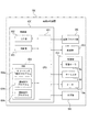
図10に示すように、画像形成装置100の内部では、主に、画像プロセス部(画像形成部C)200、給送部300、定着部(定着装置118)400、及び光学部500が、制御部(制御手段)600に接続されている。
As shown in FIG. 10, inside the
制御部600は、CPU(Central Processing Unit)601、I/F(インターフェース)部602、RAM(Random Access Memory)603、ROM(Read Only Memory)604を含む。
The
CPU601は、ROM604からプログラムを読み出して実行することで各処理を実行する。
The
I/F部602は、CPU601とLAN等のネットワークとを接続するためのデバイスであり、具体的には、LANカードやLANボード等で実現される。I/F部602は、外部から送信される画像形成の実行指示を受信してCPU601に送出する。
The I /
記憶手段としてのRAM603は、CPU601がプログラムを実行するときに必要となるデータ等を保持する。RAM603には、コピー時における定着ローラ401の目標温度が保持されている。特に、本実施形態においては、クリーニング時の定着ローラ118aの目標温度や、ヒータ118eの動作停止後、サーミスタ118dと定着ローラ118aの間にトナーが堆積している状態での定着ローラ118aや、分離爪118gの表面温度をサーミスタ118dのデータをもとに予測する温度テーブルも保持されている。
A
ROM604は、CPU601が実行する、画像形成装置101を制御するためのプログラムが保持されている。特に、ROM604には、本発明に関連して、クリーニング制御プログラム604a、温調制御プログラム604b、及び回転制御プログラム604cが保持されている。
The
クリーニング制御プログラム604aは、画像形成装置の状態によりクリーニング動作を実行するか否かを判断するプログラムである。温調制御プログラム604bは、コピー時やクリーニング動作時に、RAM603に保持されている目標温度に基づいて、サーミスタで検出された温度データを監視しながらヒータ118eのON、OFFを制御して定着ローラ118aの温調を行う。回転制御プログラム604cは、ウォームアップ時、待機時、定着時、及び待機状態と定着状態との間に、定着ローラ118aの回転の実行、停止を制御する機能を有する。
The
特に、実施例1のクリーニング時は、検出されたサーミスタ118dの温度データとサーミスタ118dのデータをもとに予測された定着ローラ118aの表面温度に基づき、定着ローラ118aの回転や停止の回転制御を行う。一方、実施例2のクリーニング時は、クリーニングシートの搬送タイミングを同期させる回転制御を行う。
In particular, during the cleaning of the first embodiment, rotation control of rotation and stop of the fixing
なお、本発明は前述した実施例に限定されるものではない。前記制御手段は、前記熱源の動作によって、前記温度検知部材の検知温度が、現像剤の軟化点を超える温度で、かつ、前記温度検知部材の検知温度が前記加熱部材の前記温度検知部材と当接していない領域の表面温度より高くなったとき、前記加熱部材を一回転未満回転した後、停止する制御を行えばよい。さらに、前記温度検知部材の検知温度が、現像剤の軟化点より低い温度になったとき、前記加熱部材を一回転以上回転する制御を行えばよい。 In addition, this invention is not limited to the Example mentioned above. The control means is configured so that the detected temperature of the temperature detecting member exceeds the softening point of the developer by the operation of the heat source, and the detected temperature of the temperature detecting member matches the temperature detecting member of the heating member. When the surface temperature of the non-contact area becomes higher, the heating member may be controlled to stop after rotating less than one rotation. Further, when the detected temperature of the temperature detecting member becomes lower than the softening point of the developer, the heating member may be controlled to rotate one or more times.
A …画像形成装置本体
B …スキャナ部
C …画像形成部
D …シートデッキ
118 …定着装置
118a …定着ローラ
118b …加圧ローラ
118d …温度検知部材(サーミスタ)
118e …定着ヒータ
118g …分離爪
600 …制御部
601 …CPU
603 …RAM
A: Image forming apparatus main body B: Scanner section C: Image forming section D: Sheet deck 118: Fixing
118e ... fixing
603 ... RAM
Claims (6)
前記回転ユニットの外周面の温度を検知する温度検知手段と、
前記温度検知手段の検知温度が、現像剤が軟化する所定の温度領域で、かつ、前記回転ユニットの表面温度より高いと判定される場合に、前記回転ユニットを回転させて、前記温度検知手段及び記録媒体を前記回転ユニットから分離するための分離手段の少なくともいずれか一方の表面を清掃する制御手段と、を有することを特徴とする画像形成装置。 Fixing means for fixing an image formed of a developer on a recording medium by heating while being nipped and conveyed by a rotating unit;
Temperature detecting means for detecting the temperature of the outer peripheral surface of the rotating unit;
When it is determined that the detected temperature of the temperature detecting means is in a predetermined temperature range where the developer is softened and higher than the surface temperature of the rotating unit, the rotating unit is rotated, and the temperature detecting means and An image forming apparatus comprising: a control unit that cleans at least one surface of a separating unit that separates the recording medium from the rotating unit.
Priority Applications (1)
| Application Number | Priority Date | Filing Date | Title |
|---|---|---|---|
| JP2012283069A JP6025552B2 (en) | 2012-12-26 | 2012-12-26 | Image forming apparatus |
Applications Claiming Priority (1)
| Application Number | Priority Date | Filing Date | Title |
|---|---|---|---|
| JP2012283069A JP6025552B2 (en) | 2012-12-26 | 2012-12-26 | Image forming apparatus |
Publications (3)
| Publication Number | Publication Date |
|---|---|
| JP2014126681A JP2014126681A (en) | 2014-07-07 |
| JP2014126681A5 JP2014126681A5 (en) | 2016-06-16 |
| JP6025552B2 true JP6025552B2 (en) | 2016-11-16 |
Family
ID=51406227
Family Applications (1)
| Application Number | Title | Priority Date | Filing Date |
|---|---|---|---|
| JP2012283069A Expired - Fee Related JP6025552B2 (en) | 2012-12-26 | 2012-12-26 | Image forming apparatus |
Country Status (1)
| Country | Link |
|---|---|
| JP (1) | JP6025552B2 (en) |
Family Cites Families (8)
| Publication number | Priority date | Publication date | Assignee | Title |
|---|---|---|---|---|
| JPH10149049A (en) * | 1996-11-20 | 1998-06-02 | Fuji Xerox Co Ltd | Cleaning method and device for separating material of image fixing device |
| JP2003076204A (en) * | 2001-09-07 | 2003-03-14 | Canon Inc | Image forming device |
| JP4187503B2 (en) * | 2002-10-31 | 2008-11-26 | キヤノンファインテック株式会社 | Image forming apparatus |
| JP2004309569A (en) * | 2003-04-02 | 2004-11-04 | Canon Inc | Fixing device and image forming device |
| JP2006058742A (en) * | 2004-08-23 | 2006-03-02 | Canon Inc | Image forming apparatus |
| JP2007086208A (en) * | 2005-09-20 | 2007-04-05 | Sharp Corp | Fixing apparatus and image forming apparatus |
| JP2008134325A (en) * | 2006-11-27 | 2008-06-12 | Sharp Corp | Roller drive control method for fixing device |
| JP2009092683A (en) * | 2007-10-03 | 2009-04-30 | Sharp Corp | Electrophotographic image forming apparatus |
-
2012
- 2012-12-26 JP JP2012283069A patent/JP6025552B2/en not_active Expired - Fee Related
Also Published As
| Publication number | Publication date |
|---|---|
| JP2014126681A (en) | 2014-07-07 |
Similar Documents
| Publication | Publication Date | Title |
|---|---|---|
| JP5665485B2 (en) | Image forming apparatus | |
| JP5574806B2 (en) | Image forming apparatus | |
| US10018950B2 (en) | Image forming apparatus with switching rotational direction of developer carrier in correspondence with inner temperature | |
| JP5105987B2 (en) | Image forming apparatus and method for cleaning fixing member of image forming apparatus | |
| JP6039270B2 (en) | Fixing device | |
| US10191417B2 (en) | Fixing device having a cover member that covers a fixation roller | |
| JP5451513B2 (en) | Image forming apparatus | |
| JP2011081136A (en) | Fixing device | |
| JP2009037078A (en) | Fixing device and image forming apparatus having the same | |
| JP6025552B2 (en) | Image forming apparatus | |
| JP2012027168A (en) | Fixing device and image forming apparatus | |
| JP2015158535A (en) | fixing device | |
| JP2004258185A (en) | Image forming device | |
| JP4517864B2 (en) | Image forming apparatus | |
| JP5190795B2 (en) | Transfer fixing device and image forming apparatus | |
| JP5294058B2 (en) | Image removal apparatus and image formation removal system | |
| JP5407580B2 (en) | Image removal apparatus and image formation removal system | |
| JP2005203181A (en) | Heating apparatus and image forming apparatus | |
| JP2011191557A (en) | Image removing device, and image forming and removing system | |
| JP5168655B2 (en) | Image removal apparatus and image formation removal system | |
| JP2003307968A (en) | Image forming device | |
| JP2012003103A (en) | Image removing device and image forming/removing system | |
| JP5759531B2 (en) | Image forming apparatus | |
| JP5282682B2 (en) | Image removal apparatus and image formation removal system | |
| JP5496644B2 (en) | Fixing apparatus and image forming apparatus |
Legal Events
| Date | Code | Title | Description |
|---|---|---|---|
| A621 | Written request for application examination |
Free format text: JAPANESE INTERMEDIATE CODE: A621 Effective date: 20151225 |
|
| A521 | Written amendment |
Free format text: JAPANESE INTERMEDIATE CODE: A523 Effective date: 20160427 |
|
| TRDD | Decision of grant or rejection written | ||
| A01 | Written decision to grant a patent or to grant a registration (utility model) |
Free format text: JAPANESE INTERMEDIATE CODE: A01 Effective date: 20160927 |
|
| A61 | First payment of annual fees (during grant procedure) |
Free format text: JAPANESE INTERMEDIATE CODE: A61 Effective date: 20161011 |
|
| R150 | Certificate of patent or registration of utility model |
Ref document number: 6025552 Country of ref document: JP Free format text: JAPANESE INTERMEDIATE CODE: R150 |
|
| S533 | Written request for registration of change of name |
Free format text: JAPANESE INTERMEDIATE CODE: R313533 |
|
| R350 | Written notification of registration of transfer |
Free format text: JAPANESE INTERMEDIATE CODE: R350 |
|
| LAPS | Cancellation because of no payment of annual fees |