JP6025519B2 - Image processing apparatus and image processing method - Google Patents

Image processing apparatus and image processing method Download PDF

Info

Publication number
JP6025519B2
JP6025519B2 JP2012255530A JP2012255530A JP6025519B2 JP 6025519 B2 JP6025519 B2 JP 6025519B2 JP 2012255530 A JP2012255530 A JP 2012255530A JP 2012255530 A JP2012255530 A JP 2012255530A JP 6025519 B2 JP6025519 B2 JP 6025519B2
Authority
JP
Japan
Prior art keywords
image
shadow
stereoscopic
virtual object
data
Prior art date
Legal status (The legal status is an assumption and is not a legal conclusion. Google has not performed a legal analysis and makes no representation as to the accuracy of the status listed.)
Active
Application number
JP2012255530A
Other languages
Japanese (ja)
Other versions
JP2014103599A5 (en
JP2014103599A (en
Inventor
千晶 金子
千晶 金子
Current Assignee (The listed assignees may be inaccurate. Google has not performed a legal analysis and makes no representation or warranty as to the accuracy of the list.)
Canon Inc
Original Assignee
Canon Inc
Priority date (The priority date is an assumption and is not a legal conclusion. Google has not performed a legal analysis and makes no representation as to the accuracy of the date listed.)
Filing date
Publication date
Application filed by Canon Inc filed Critical Canon Inc
Priority to JP2012255530A priority Critical patent/JP6025519B2/en
Publication of JP2014103599A publication Critical patent/JP2014103599A/en
Publication of JP2014103599A5 publication Critical patent/JP2014103599A5/ja
Application granted granted Critical
Publication of JP6025519B2 publication Critical patent/JP6025519B2/en
Active legal-status Critical Current
Anticipated expiration legal-status Critical

Links

Images

Description

本発明は立体像表示技術における画像処理に関する。   The present invention relates to image processing in stereoscopic image display technology.

従来、コンピュータグラフィックスによって表現された仮想物体の影を作成する方法としては、現実空間を撮像した画像上に、その撮像シーンの光源環境を用いて仮想物体とその影を合成する画像合成技術が知られている(例えば、特許文献1)。この画像合成技術は、現実空間の複数の位置について設定された光のパラメータの中から、仮想物体が置かれた位置に対応するものを参照することで、現実空間における光源環境を適正に反映した影を画像内に作成するものであった。   Conventionally, as a method of creating a shadow of a virtual object represented by computer graphics, there is an image composition technique for synthesizing a virtual object and its shadow on an image obtained by capturing a real space by using a light source environment of the imaging scene. Known (for example, Patent Document 1). This image composition technology appropriately reflects the light source environment in the real space by referring to the light parameters set for a plurality of positions in the real space corresponding to the positions where the virtual objects are placed. A shadow was created in the image.

特開2011−60195号公報JP 2011-60195 A

しかしながら、上記従来技術は、あくまで画像内に仮想物体の影を作成するものである。現在、両眼視差を利用して観察者に立体像を知覚させる3D画像表示技術が普及している。この技術は、同一の仮想物体に関して両眼の視差の分だけ見え方の異なる画像(視差画像)を左右それぞれの眼に別個に提示することにより立体像を知覚させる技術である。このような画面から飛び出して見える立体像によって生じるべき影を、現実空間における床や壁などに作成することは、上記従来技術では不可能である。   However, the above-described conventional technique only creates a shadow of a virtual object in an image. Currently, 3D image display technology that allows a viewer to perceive a stereoscopic image using binocular parallax has become widespread. This technique is a technique for perceiving a three-dimensional image by separately presenting to the left and right eyes images (parallax images) that differ in appearance by the amount of parallax between both eyes with respect to the same virtual object. It is impossible with the above-described conventional technology to create a shadow to be generated by a stereoscopic image that appears to jump out of such a screen on a floor or a wall in a real space.

本発明に係る画像処理装置は、視差画像を表示することにより仮想物体の立体像を観察者に知覚させる場合における、当該立体像の擬似的な影を現実空間に作成するための陰影画像を、前記仮想物体の位置及び形状を特定するデータと、前記陰影画像を現実空間に投影する画像投影手段による投影領域の位置と大きさを示す情報とに基づいて生成する、ことを特徴とする。   The image processing apparatus according to the present invention, when displaying a parallax image to make an observer perceive a stereoscopic image of a virtual object, creates a shadow image for creating a pseudo shadow of the stereoscopic image in a real space. It is generated based on data specifying the position and shape of the virtual object, and information indicating the position and size of the projection area by the image projection means for projecting the shadow image onto the real space.

本発明によれば、視差画像によって生み出される立体像の擬似的な影等を現実空間に作成することができる。これにより、映像の臨場感が向上する。   According to the present invention, a pseudo shadow or the like of a stereoscopic image generated by a parallax image can be created in a real space. Thereby, the realistic sensation of the video is improved.

実施例1に係る立体像表示システム100のシステム構成例を示す図である。1 is a diagram illustrating a system configuration example of a stereoscopic image display system 100 according to Embodiment 1. FIG. 画像処理装置の内部構成を示す図である。It is a figure which shows the internal structure of an image processing apparatus. 実施例1に係る画像処理装置の機能ブロック図である。1 is a functional block diagram of an image processing apparatus according to Embodiment 1. FIG. 実施例1に係る画像処理装置における一連の処理の流れを示すフローチャートである。3 is a flowchart illustrating a flow of a series of processes in the image processing apparatus according to the first embodiment. 観察者の視点位置と立体表示領域との関係を示す図である。It is a figure which shows the relationship between an observer's viewpoint position and a three-dimensional display area. 仮想物体が配置された視差画像の一例を示す図である。It is a figure which shows an example of the parallax image by which the virtual object is arrange | positioned. 陰影画像の生成過程を説明する図である。It is a figure explaining the production | generation process of a shadow image. 陰影画像の一例を示す図である。It is a figure which shows an example of a shadow image. 実施例2に係る画像処理装置の機能ブロック図である。FIG. 6 is a functional block diagram of an image processing apparatus according to a second embodiment. 実施例2に係る画像処理装置における一連の処理の流れを示すフローチャートである。12 is a flowchart illustrating a flow of a series of processes in the image processing apparatus according to the second embodiment. 実施例2に係る、立体像の位置を導出する処理の流れを示すフローチャートである。12 is a flowchart illustrating a flow of processing for deriving a position of a stereoscopic image according to the second embodiment. 立体像の位置が導出される過程を説明する図である。It is a figure explaining the process in which the position of a stereo image is derived | led-out.

[実施例1]
実施例1では、仮想物体の位置および形状を表すモデルデータを立体像の位置情報として取得し、この位置情報に応じた陰影画像を生成して、生成された陰影画像を現実空間に投影することで、立体像の擬似的な影を現実空間に作成する態様について説明する。
[Example 1]
In the first embodiment, model data representing the position and shape of a virtual object is acquired as position information of a stereoscopic image, a shadow image corresponding to this position information is generated, and the generated shadow image is projected onto a real space. Now, an aspect of creating a pseudo shadow of a stereoscopic image in the real space will be described.

図1は、本実施例に係る立体像表示システム100のシステム構成例を示す図である。立体像表示システム100は、陰影画像の生成処理などを行う画像処理装置101、立体像表示装置としての液晶3Dディスプレイ102、画像投影装置としての液晶プロジェクタ103で構成される。   FIG. 1 is a diagram illustrating a system configuration example of a stereoscopic image display system 100 according to the present embodiment. The stereoscopic image display system 100 includes an image processing apparatus 101 that performs a shadow image generation process, a liquid crystal 3D display 102 as a stereoscopic image display apparatus, and a liquid crystal projector 103 as an image projection apparatus.

本実施例の画像処理装置101は、モデルデータを用いて、左眼用画像と右眼用画像とからなる視差画像を生成する。生成された視差画像のデータは液晶3Dディスプレイ102によって表示され、これにより仮想物体の立体像104が表示される。また、画像処理装置101は、モデルデータに応じた陰影画像105を生成する。生成された陰影画像のデータは液晶プロジェクタ103によって現実空間の床に投影され、これにより立体像の擬似的な影が作成される。   The image processing apparatus 101 according to the present exemplary embodiment generates a parallax image including a left-eye image and a right-eye image using model data. The generated parallax image data is displayed on the liquid crystal 3D display 102, thereby displaying a stereoscopic image 104 of the virtual object. In addition, the image processing apparatus 101 generates a shadow image 105 according to the model data. The generated shadow image data is projected onto the floor in the real space by the liquid crystal projector 103, thereby creating a pseudo shadow of the stereoscopic image.

なお、以下では、本実施例中で用いる3次元座標の原点を液晶3Dディスプレイ102の画面中心Oとし、x軸、y軸、z軸をそれぞれ液晶3Dディスプレイ102の水平方向、鉛直方向、法線方向として説明する。   In the following, the origin of the three-dimensional coordinates used in this embodiment is the screen center O of the liquid crystal 3D display 102, and the x, y, and z axes are the horizontal, vertical, and normal lines of the liquid crystal 3D display 102, respectively. This will be described as a direction.

図2は、画像処理装置101の内部構成を示す図である。   FIG. 2 is a diagram illustrating an internal configuration of the image processing apparatus 101.

画像処理装置101は、CPU201、RAM202、ROM203、ハードディスクドライブ(HDD)204、HDDI/F205、入力I/F206、出力I/F207、システムバス208で構成される。   The image processing apparatus 101 includes a CPU 201, RAM 202, ROM 203, hard disk drive (HDD) 204, HDD I / F 205, input I / F 206, output I / F 207, and system bus 208.

CPU201は、RAM202をワークメモリとして、ROM203及びHDD204に格納されたプログラムを実行し、システムバス208を介して後述する各構成を統括的に制御する。これにより、後述する様々な処理が実行される。   The CPU 201 executes programs stored in the ROM 203 and the HDD 204 using the RAM 202 as a work memory, and comprehensively controls each component to be described later via the system bus 208. Thereby, various processes described later are executed.

HDDI/F205は、例えばシリアルATA(SATA)等のインタフェイスであり、二次記憶装置としてのHDD204を接続する。CPU201は、HDDI/F205を介してHDD204からのデータ読み出し、およびHDD204へのデータ書き込みが可能である。さらにCPU201は、HDD204に格納されたデータをRAM202に展開し、同様に、RAM202に展開されたデータをHDD204に保存することが可能である。そしてCPU201は、RAM202に展開したデータをプログラムとみなし、実行することができる。なお、二次記憶装置はHDDの他、光ディスクドライブ等の記憶デバイスでもよい。   The HDD I / F 205 is an interface such as serial ATA (SATA), for example, and connects the HDD 204 as a secondary storage device. The CPU 201 can read data from the HDD 204 and write data to the HDD 204 via the HDD I / F 205. Further, the CPU 201 can expand the data stored in the HDD 204 in the RAM 202 and similarly can store the data expanded in the RAM 202 in the HDD 204. The CPU 201 can regard the data expanded in the RAM 202 as a program and execute it. The secondary storage device may be a storage device such as an optical disk drive in addition to the HDD.

入力I/F206は、例えばUSBやIEEE1394等のシリアルバスインタフェイスである。入力I/F206は、キーボード・マウス209などの各種入力デバイスや、赤外線や電磁波などを用いた位置センサ210を接続する。CPU201は、入力I/F206を介してキーボード・マウス209や位置センサ210から様々なデータを取得することが可能である。   The input I / F 206 is a serial bus interface such as USB or IEEE1394. The input I / F 206 connects various input devices such as a keyboard / mouse 209 and a position sensor 210 using infrared rays or electromagnetic waves. The CPU 201 can acquire various data from the keyboard / mouse 209 and the position sensor 210 via the input I / F 206.

出力I/F207は、例えばDVIやHDMI等の映像出力インタフェイスであり、液晶3Dディスプレイ102およびプロジェクタ103を接続する。この出力I/F207を介して、液晶3Dディスプレイ102に視差画像データが送られ、液晶プロジェクタ103に陰影画像データが送られる。視差画像データを受け取った液晶3Dディスプレイ102は、その画面上に視差画像を表示する。(以後、立体像表示装置における視差画像が表示される画面領域を「立体像表示領域」と呼ぶ。)また、陰影画像データを受け取った液晶プロジェクタ103は、現実空間の床などに陰影画像を投影する。   The output I / F 207 is a video output interface such as DVI or HDMI, and connects the liquid crystal 3D display 102 and the projector 103. Through this output I / F 207, parallax image data is sent to the liquid crystal 3D display 102, and shadow image data is sent to the liquid crystal projector 103. The liquid crystal 3D display 102 that has received the parallax image data displays the parallax image on the screen. (Hereinafter, the screen area on which the parallax image is displayed in the stereoscopic image display device is referred to as a “stereoscopic image display area”.) The liquid crystal projector 103 that has received the shadow image data projects the shadow image onto a floor or the like in the real space. To do.

なお、図1に示すシステムでは立体像表示装置として液晶3Dディスプレイ102を用いているが、これに限られない。例えば、液晶3Dディスプレイに代えてプラズマ3Dディスプレイや有機EL3Dディスプレイを用いてもよい。また、画像投影装置として液晶プロジェクタ103を用いているが、DLPプロジェクタやLCOSプロジェクタであっても構わない。   In the system shown in FIG. 1, the liquid crystal 3D display 102 is used as the stereoscopic image display device, but is not limited thereto. For example, a plasma 3D display or an organic EL 3D display may be used instead of the liquid crystal 3D display. Further, although the liquid crystal projector 103 is used as the image projection apparatus, a DLP projector or an LCOS projector may be used.

図3は、本実施例に係る画像処理装置101の機能ブロック図である。画像処理装置101は、視点位置情報取得部301、表示領域情報取得部302、モデルデータ取得部303、投影特性情報取得部304、視差画像生成部305、投影画像生成部306で構成される。   FIG. 3 is a functional block diagram of the image processing apparatus 101 according to the present embodiment. The image processing apparatus 101 includes a viewpoint position information acquisition unit 301, a display area information acquisition unit 302, a model data acquisition unit 303, a projection characteristic information acquisition unit 304, a parallax image generation unit 305, and a projection image generation unit 306.

視点位置情報取得部301は、観察者の左右の眼の位置を示す情報(以下、「視点位置情報」と呼ぶ。)を取得する。本実施例では、観察者の左右の眼の位置を示す3次元座標EL(xL0,yL0,zL0)、ER(xR0,yR0,zR0)が、例えば位置センサ210を介して取得される。或いは、観察者の顔を撮像する複数のカメラを別途用意し、得られた複数の顔画像に対し顔認識技術を用いて画像上における眼の位置を求め、得られた画像上の眼の位置と撮像したカメラの姿勢情報とに基づいて、左右の眼の3次元座標を導出してもよい。取得した視点位置情報は、視差画像生成部305に送られる。   The viewpoint position information acquisition unit 301 acquires information indicating the positions of the left and right eyes of the observer (hereinafter referred to as “viewpoint position information”). In the present embodiment, three-dimensional coordinates EL (xL0, yL0, zL0) and ER (xR0, yR0, zR0) indicating the positions of the left and right eyes of the observer are acquired via the position sensor 210, for example. Alternatively, a plurality of cameras that capture the face of the observer are prepared separately, and the position of the eye on the obtained image is obtained by using face recognition technology for the obtained face images, and the position of the eye on the obtained image And three-dimensional coordinates of the left and right eyes may be derived based on the captured camera posture information. The acquired viewpoint position information is sent to the parallax image generation unit 305.

表示領域情報取得部302は、立体像表示装置(ここでは、液晶3Dディスプレイ102)における立体像表示領域のサイズ(W×H)の情報(以下、「表示領域情報」と呼ぶ。)を取得する。立体像表示領域のサイズは、例えば、16:9の50インチのディスプレイの場合であれば、W:110cm、H:62cm、のような値となる。この表示領域情報の取得は、例えばキーボード・マウス209等を介したユーザ入力によって行ってもよいし或いは予めHDD204などに記憶しておきそれを読み込むことで取得してもよい。取得した表示領域情報は、視差画像生成部305に送られる。   The display area information acquisition unit 302 acquires information (hereinafter referred to as “display area information”) of the size (W × H) of the stereoscopic image display area in the stereoscopic image display device (here, the liquid crystal 3D display 102). . For example, in the case of a 16: 9 50-inch display, the size of the stereoscopic image display area is a value such as W: 110 cm and H: 62 cm. The display area information may be acquired by a user input via the keyboard / mouse 209 or the like, or may be acquired by storing in advance in the HDD 204 or the like and reading it. The acquired display area information is sent to the parallax image generation unit 305.

モデルデータ取得部303は、立体像として表示される仮想物体の位置および形状を特定するモデルデータを、HDDI/F205を介してHDD204などの二次記憶装置から取得する。本実施例におけるモデルデータはメッシュデータとする。ここで、メッシュデータとは、複数の辺を有する板状の要素の集合で物体の形状を表現するメッシュモデルの表示に必要なデータ(例えば四辺形の各頂点の座標データ等)のことである。モデルデータのデータ形式は、仮想物体の位置と形状を特定できるものであればよく、例えば、NURBS曲面などで表現されるパラメトリックモデルでもよい。さらに、モデルデータは、仮想物体の反射率、透過率、屈折率など、仮想物体の色や質感を表す情報を含んでいてもよい。本実施例では、モデルデータは立体像の位置情報として用いられる。取得したモデルデータは、視差画像生成部305及び投影画像生成部306へ送られる。   The model data acquisition unit 303 acquires model data for specifying the position and shape of a virtual object displayed as a stereoscopic image from a secondary storage device such as the HDD 204 via the HDD I / F 205. The model data in this embodiment is mesh data. Here, the mesh data is data necessary for displaying a mesh model that expresses the shape of an object with a set of plate-like elements having a plurality of sides (for example, coordinate data of each vertex of a quadrilateral). . The data format of the model data is not particularly limited as long as the position and shape of the virtual object can be specified. For example, the model data may be a parametric model expressed by a NURBS surface. Further, the model data may include information representing the color and texture of the virtual object such as the reflectance, transmittance, and refractive index of the virtual object. In this embodiment, the model data is used as the position information of the stereoscopic image. The acquired model data is sent to the parallax image generation unit 305 and the projection image generation unit 306.

投影特性情報取得部304は、陰影画像を投影する画像投影装置(ここでは液晶プロジェクタ103)の投影領域の位置と大きさを示す投影特性の情報を取得する。本実施例では、液晶プロジェクタ103の位置を示す3次元座標P0(x0,y0,z0)、液晶プロジェクタ103の光軸が通過する点P1(x1,y1,z1)、水平画角θ、垂直画角ψ、水平解像度Wp、垂直解像度Hpを投影特性として用いている。この投影特性情報は、予め測定して得られたデータをHDD204等に記憶しておき、処理実行時にHDDI/F205を介して読み込んで取得する。或いは、液晶プロジェクタ103に別途位置センサや傾きセンサを取り付け、入力I/F206を介して位置や向きを取得してもよいし、液晶プロジェクタ103から双方向通信可能な出力I/F207を介して画角を取得してもよい。取得した投影特性情報は、投影画像生成部306へ送られる。   The projection characteristic information acquisition unit 304 acquires projection characteristic information indicating the position and size of the projection area of an image projection apparatus (here, the liquid crystal projector 103) that projects a shadow image. In this embodiment, the three-dimensional coordinates P0 (x0, y0, z0) indicating the position of the liquid crystal projector 103, the point P1 (x1, y1, z1) through which the optical axis of the liquid crystal projector 103 passes, the horizontal angle of view θ, the vertical image Angle ψ, horizontal resolution Wp, and vertical resolution Hp are used as projection characteristics. The projection characteristic information is obtained by storing data obtained by measurement in advance in the HDD 204 or the like, and reading it through the HDD I / F 205 at the time of processing execution. Alternatively, a separate position sensor or tilt sensor may be attached to the liquid crystal projector 103, and the position and orientation may be acquired via the input I / F 206, or the image may be displayed via the output I / F 207 capable of bidirectional communication from the liquid crystal projector 103. A corner may be acquired. The acquired projection characteristic information is sent to the projection image generation unit 306.

視差画像生成部305は、受け取った視点位置情報、表示領域情報及びモデルデータを用いて、互いに視差のある左眼用画像と右眼用画像とからなる視差画像を生成する。生成された視差画像のデータは液晶3Dディスプレイ102に送られる。   The parallax image generation unit 305 generates a parallax image composed of a left-eye image and a right-eye image having parallax using the received viewpoint position information, display area information, and model data. The generated parallax image data is sent to the liquid crystal 3D display 102.

投影画像生成部305は、受け取ったモデルデータ及び投影特性情報を用いて、投影の対象となる画像(ここでは陰影画像)を生成する。生成された陰影画像のデータは液晶プロジェクタ103に送られる。   The projection image generation unit 305 generates an image to be projected (here, a shadow image) using the received model data and projection characteristic information. The generated shadow image data is sent to the liquid crystal projector 103.

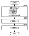
図4は、本実施例に係る画像処理装置101における一連の処理の流れを示すフローチャートである。なお、この一連の処理は、以下に示す手順を記述したコンピュータ実行可能なプログラムを、ROM203あるいはHDD204からRAM202上に読み込んだ後、該プログラムがCPU201で実行されることによって実現される。   FIG. 4 is a flowchart showing a flow of a series of processes in the image processing apparatus 101 according to the present embodiment. This series of processing is realized by reading a computer-executable program describing the following procedure from the ROM 203 or HDD 204 onto the RAM 202 and then executing the program by the CPU 201.

ステップ401において、各取得部301〜304は、上述した視点位置情報、表示領域情報、モデルデータ、投影特性情報を、それぞれHDD204等から取得する。取得された各情報は、上述のとおり視差画像生成部305及び/又は投影画像生成部306に送られる。   In step 401, the acquisition units 301 to 304 acquire the above-described viewpoint position information, display area information, model data, and projection characteristic information from the HDD 204 and the like, respectively. Each acquired information is sent to the parallax image generation unit 305 and / or the projection image generation unit 306 as described above.

ステップ402において、視差画像生成部305は、受け取った視点位置情報、表示領域情報及びモデルデータを用いて視差画像を生成する。具体的には、視点位置情報によって示される左右それぞれの眼の位置から、表示領域情報によって示される立体像表示領域越しに見える仮想空間のシーンをレンダリングして、視差画像を生成する。本実施例においては、レンダリングに用いる仮想カメラの位置を観察者の視点位置とする。また、仮想カメラの光軸方向は、観察者の視点位置を通り立体像表示領域に垂直なベクトルと一致するものとする。図5の(a)は現実空間における観察者の視点位置と立体表示領域(液晶3Dプロジェクタ102)との関係を示しており、同(b)は仮想空間における観察者の視点位置と立体表示領域との関係を示している。モデルデータにより示される仮想物体501が配置された仮想空間中において、観察者の視点位置(左眼:EL、右眼:ER)から立体像表示領域の四隅(r0〜r3)へ向かう4つのベクトルで囲まれる範囲をレンダリングする。このように、観察者の右眼と左眼それぞれの位置を視点位置としてレンダリング処理を行うことで、互いに視差のある左眼用画像と右眼用画像とからなる視差画像が生成される。図6は、仮想物体501が配置された視差画像の一例を示す図であり、(a)は左眼用画像、(b)は右眼用画像を示している。生成された視差画像のデータは液晶3Dディスプレイ102に送られる。上記のようにして得られた視差画像を所定の3D画像表示方式に従って液晶3Dディスプレイで表示することで、現実空間において、モデルデータで示された所定の位置に仮想物体の立体像が存在するように観察者に知覚させることができる。   In step 402, the parallax image generation unit 305 generates a parallax image using the received viewpoint position information, display area information, and model data. Specifically, a parallax image is generated by rendering a scene in a virtual space that appears over the stereoscopic image display area indicated by the display area information from the positions of the left and right eyes indicated by the viewpoint position information. In this embodiment, the position of the virtual camera used for rendering is set as the observer's viewpoint position. The optical axis direction of the virtual camera is assumed to coincide with a vector that passes through the observer's viewpoint position and is perpendicular to the stereoscopic image display area. 5A shows the relationship between the observer's viewpoint position in the real space and the stereoscopic display area (liquid crystal 3D projector 102), and FIG. 5B shows the observer's viewpoint position and the stereoscopic display area in the virtual space. Shows the relationship. Four vectors from the observer's viewpoint position (left eye: EL, right eye: ER) toward the four corners (r0 to r3) of the stereoscopic image display area in the virtual space where the virtual object 501 indicated by the model data is arranged Render the range enclosed by. In this way, by performing rendering processing using the positions of the right eye and left eye of the observer as viewpoint positions, a parallax image composed of a left-eye image and a right-eye image that have a parallax with each other is generated. 6A and 6B are diagrams illustrating an example of a parallax image in which a virtual object 501 is arranged, in which FIG. 6A illustrates an image for the left eye, and FIG. 6B illustrates an image for the right eye. The generated parallax image data is sent to the liquid crystal 3D display 102. By displaying the parallax image obtained as described above on the liquid crystal 3D display according to a predetermined 3D image display method, a stereoscopic image of the virtual object exists at a predetermined position indicated by the model data in the real space. Can be perceived by the observer.

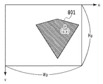
ステップ403において、投影画像生成部306は、受け取ったモデルデータ内のメッシュデータ及び投影特性情報を用いて陰影画像を生成する。以下、液晶プロジェクタ103の解像度と同じ解像度(Wp×Hp:例えば、1920×1080)の陰影画像fを、256階調のグレイスケール画像として生成する場合を例に詳しく説明する。図7は陰影画像の生成過程を説明する図であり、(a)は斜め上方から見た場合、(b)は−x方向から見た場合(x0=x1)をそれぞれ示している。   In step 403, the projection image generation unit 306 generates a shadow image using the mesh data and the projection characteristic information in the received model data. Hereinafter, an example in which a shadow image f having the same resolution (Wp × Hp: for example, 1920 × 1080) as the resolution of the liquid crystal projector 103 is generated as a 256 gray scale image will be described in detail. FIGS. 7A and 7B are diagrams for explaining the process of generating a shadow image. FIG. 7A shows a case when viewed from obliquely above, and FIG. 7B shows a case when viewed from the −x direction (x0 = x1).

まず、Wp×Hp画素の陰影画像fについて、画素値をすべて255に初期化する。そして、液晶プロジェクタ103の位置を示す点P0(x0,y0,z0)から陰影画像平面701上の任意の点Qを通って延びる直線Lが、仮想物体の表面形状を表す板状の要素(以下、単に「メッシュ」と呼ぶ)702と交差するか否かを判定する。直線Lがメッシュ702と交差すると判定された場合には当該点Qに対応する陰影画像f上の画素の画素値を0等に設定し、影部分を示す黒画素等とする。一方、交差しないと判定された場合には当該点Qに対応する陰影画像f上の画素値は初期値(すなわち、255)のままとする。交差しないと判定された場合において、当該点Qに対応する陰影画像f上の画素値を、0以外の所定の値(例えば、メッシュが存在する仮想空間や陰影画像が投影される現実空間における照度等の照明条件に応じて決定)としてもよい。ここで、陰影画像平面とは、その中心において液晶プロジェクタ103の光軸(すなわち、直線P0-P1)と直交する仮想的な平面である。液晶プロジェクタ103の光軸と陰影画像平面701との交点を原点、液晶プロジェクタの水平方向を横軸s、鉛直方向を縦軸tとすると、陰影画像fの画素(u,v)に対応する陰影画像平面上の点Qの座標(s,t)は次の式(1)及び式(2)で求められる。   First, for the shadow image f of Wp × Hp pixels, all pixel values are initialized to 255. A straight line L extending from an arbitrary point Q on the shadow image plane 701 from the point P0 (x0, y0, z0) indicating the position of the liquid crystal projector 103 is a plate-like element (hereinafter referred to as a surface shape of the virtual object). , Simply referred to as “mesh”) 702. When it is determined that the straight line L intersects with the mesh 702, the pixel value of the pixel on the shadow image f corresponding to the point Q is set to 0 or the like, and the black pixel or the like indicating the shadow portion is set. On the other hand, when it is determined not to intersect, the pixel value on the shadow image f corresponding to the point Q is left at the initial value (ie, 255). If it is determined that they do not intersect, the pixel value on the shadow image f corresponding to the point Q is set to a predetermined value other than 0 (for example, the illuminance in the virtual space where the mesh exists or the real space where the shadow image is projected) It is good also as determined according to lighting conditions, such as. Here, the shadow image plane is a virtual plane that is orthogonal to the optical axis of the liquid crystal projector 103 (that is, the straight line P0-P1) at the center thereof. If the intersection of the optical axis of the liquid crystal projector 103 and the shadow image plane 701 is the origin, the horizontal direction of the liquid crystal projector is the horizontal axis s, and the vertical direction is the vertical axis t, the shadow corresponding to the pixel (u, v) of the shadow image f The coordinates (s, t) of the point Q on the image plane can be obtained by the following equations (1) and (2).

Figure 0006025519
Figure 0006025519

Figure 0006025519
Figure 0006025519

ここで、Dは点P0(x0,y0,z0)から陰影画像平面701までの距離である。また、θは点P0(x0,y0,z0)と横軸s上の陰影画像平面の端点701a/701cとをそれぞれ結ぶ線分間のなす角度、ψは点P0(x0,y0,z0)と横軸s上の陰影画像平面の端点701b/701dとをそれぞれ結ぶ線分間のなす角度である。 Here, D is the distance from the point P0 (x0, y0, z0) to the shadow image plane 701. Θ is an angle formed by line segments connecting the point P0 (x0, y0, z0) and the end points 701a / 701c of the shaded image plane on the horizontal axis s, and ψ is the point P0 (x0, y0, z0) and the horizontal This is the angle formed by the line segments connecting the end points 701b / 701d of the shadow image plane on the axis s.

陰影画像fの全画素について、上記式(1)および(2)を用いて対応する点Qを求め、仮想物体の表面形状を表すメッシュ702との交差判定を行って画素値を設定することで、陰影画像fが得られる。図8は、上述した処理によって得られる陰影画像fの一例であり、立体像の対応する領域801(画素値が0等の領域)が陰影となる部分として存在している。このようにして生成された陰影画像のデータは液晶プロジェクタ103に出力され、現実空間の床などに立体像の影として投影される。   For all the pixels of the shaded image f, the corresponding points Q are obtained using the above formulas (1) and (2), intersection determination with the mesh 702 representing the surface shape of the virtual object is performed, and pixel values are set. A shadow image f is obtained. FIG. 8 is an example of the shadow image f obtained by the above-described processing, and a corresponding region 801 (region having a pixel value of 0 or the like) of the stereoscopic image exists as a shadowed portion. The shadow image data generated in this way is output to the liquid crystal projector 103 and projected as a shadow of a three-dimensional image on the floor of the real space.

この場合において、液晶プロジェクタ103と立体像との間に実物体(例えば、観察者の体の一部など)が存在する場合には、実物体の影になるメッシュに対しては影を生成しないことが望ましい。例えば、液晶プロジェクタ103の光軸に沿った距離センサを別途用意して実物体までの距離を取得し、実物体の手前(実物体よりも液晶プロジェクタ103に近い位置)に存在するメッシュに対してのみ上述の交差判定を行って陰影画像を生成すればよい。これにより実物体上に不要な影が生じるのを防止できる。   In this case, when a real object (for example, a part of the observer's body) exists between the liquid crystal projector 103 and the stereoscopic image, no shadow is generated for the mesh that becomes the shadow of the real object. It is desirable. For example, a distance sensor along the optical axis of the liquid crystal projector 103 is separately prepared to acquire the distance to the real object, and the mesh existing in front of the real object (position closer to the liquid crystal projector 103 than the real object) is obtained. Only the above-described intersection determination may be performed to generate a shadow image. Thereby, it is possible to prevent an unnecessary shadow from being generated on the real object.

なお、本実施例では仮想物体によって生み出される影を現実空間に投影する例を説明したが、例えば仮想物体により生じる擬似的な集光模様の画像を生成し、これを現実空間に投影してもよい。この場合には、投影画像生成部306は、モデルデータに含まれる仮想物体の反射率、透過率、屈折率など、仮想物体の色や質感を表す光学特性を示す情報を利用して、集光模様画像を生成することになる。具体的には、上述のステップ403において、直線Lが仮想物体内を通過する区間を求め、その距離や仮想物体の屈折率等に基づいて透過光の強度を導出し、得られる強度に応じた値で画素値を置き換えた集光模様画像(上述の陰影画像fに相当)を求めればよい。また、集光模様画像をカラー画像で生成し、透過光の強度の導出を光の波長毎に行って画素値を決定することで、より精巧な集光模様とすることができる。   In this embodiment, the example in which the shadow generated by the virtual object is projected onto the real space has been described. However, for example, a pseudo-condensing pattern image generated by the virtual object is generated and projected onto the real space. Good. In this case, the projection image generation unit 306 uses the information indicating the optical properties representing the color and texture of the virtual object such as the reflectance, transmittance, and refractive index of the virtual object included in the model data to collect the light. A pattern image is generated. Specifically, in step 403 described above, a section where the straight line L passes through the virtual object is obtained, and the intensity of the transmitted light is derived based on the distance, the refractive index of the virtual object, and the like, and according to the obtained intensity. A condensing pattern image (corresponding to the shadow image f described above) in which the pixel value is replaced with the value may be obtained. Further, by generating a condensing pattern image as a color image and deriving the intensity of transmitted light for each wavelength of light to determine pixel values, a more elaborate condensing pattern can be obtained.

以上のとおり、本実施例によれば、画面から飛び出して見える仮想物体の影等を現実空間に生じさせすることが可能となる。   As described above, according to the present embodiment, it is possible to cause a shadow or the like of a virtual object that appears to jump out of the screen in the real space.

[実施例2]
実施例1では、立体像として表示される仮想物体の位置および形状を特定するモデルデータを取得し、モデルデータで特定された立体像の位置に応じた影等を現実空間に生じさせるための陰影画像等を生成した。次に、視差画像データと観察者の視点位置情報から立体像の位置を導出して、陰影画像等を生成する態様について、実施例2として説明する。なお、実施例1と共通する部分については説明を簡略化ないしは省略し、ここでは差異点を中心に説明することとする。
[Example 2]
In the first embodiment, model data for specifying the position and shape of a virtual object displayed as a three-dimensional image is acquired, and a shadow for causing a shadow or the like according to the position of the three-dimensional image specified by the model data in the real space. Images etc. were generated. Next, an embodiment in which the position of the stereoscopic image is derived from the parallax image data and the viewpoint position information of the observer to generate a shadow image or the like will be described as a second embodiment. Note that description of parts common to the first embodiment is simplified or omitted, and here, differences will be mainly described.

図9は、本実施例に係る画像処理装置101の機能ブロック図である。なお、立体像表示システムのシステム構成は実施例1と共通であるものとする。   FIG. 9 is a functional block diagram of the image processing apparatus 101 according to the present embodiment. The system configuration of the stereoscopic image display system is the same as that of the first embodiment.

視差画像データ取得部901は、視差画像のデータを、HDDI/F205を介してHDD204などの二次記憶装置から取得する。この場合の視差画像データは、例えば多眼カメラ等で撮像して得たものでもよいし、或いは市販されている3D画像生成ソフトウェアを使って生成したものでもよい。取得した視差画像データは、立体像位置導出部905及び立体像表示装置としての液晶3Dディスプレイ102に送られる。   The parallax image data acquisition unit 901 acquires parallax image data from a secondary storage device such as the HDD 204 via the HDD I / F 205. In this case, the parallax image data may be obtained by imaging with a multi-lens camera or the like, or may be generated using commercially available 3D image generation software. The acquired parallax image data is sent to the stereoscopic image position deriving unit 905 and the liquid crystal 3D display 102 as a stereoscopic image display device.

表示領域情報取得部902は、立体像表示装置の表示領域情報を取得する。これについては実施例1に係る表示領域情報取得部302と同じである。取得した表示領域情報は、立体像位置導出部905に送られる。   The display area information acquisition unit 902 acquires display area information of the stereoscopic image display device. This is the same as the display area information acquisition unit 302 according to the first embodiment. The acquired display area information is sent to the stereoscopic image position deriving unit 905.

視点位置情報取得部903は、観察者の視点位置情報を取得する。これについては実施例1に係る視点位置情報取得部301と同じである。取得した視点位置情報は、立体像位置導出部905に送られる。   The viewpoint position information acquisition unit 903 acquires the viewpoint position information of the observer. This is the same as the viewpoint position information acquisition unit 301 according to the first embodiment. The acquired viewpoint position information is sent to the stereoscopic image position deriving unit 905.

投影特性情報取得部904は、画像投影装置の投影特性情報を取得する。これについては実施例1に係る投影特性情報取得部304と同じである。取得した投影特性情報は、投影画像生成部906に送られる。   The projection characteristic information acquisition unit 904 acquires projection characteristic information of the image projection apparatus. This is the same as the projection characteristic information acquisition unit 304 according to the first embodiment. The acquired projection characteristic information is sent to the projection image generation unit 906.

立体像位置導出部905は、受け取った視差画像データ、表示領域情報及び視点位置情報に基づき、立体像として表示される仮想物体の位置及び形状を特定可能なデータ(ここでは、前述のメッシュデータ)を生成する。   The three-dimensional image position deriving unit 905 can specify the position and shape of a virtual object displayed as a three-dimensional image based on the received parallax image data, display area information, and viewpoint position information (here, the mesh data described above) Is generated.

投影画像生成部906は、立体像位置導出部905から受け取ったメッシュデータおよび投影特性取得部904から受け取った画像投影装置の投影特性情報を用いて、陰影画像を生成する。生成された陰影画像データは、液晶プロジェクタ103に送られる。   The projection image generation unit 906 generates a shadow image using the mesh data received from the stereoscopic image position deriving unit 905 and the projection characteristic information of the image projection apparatus received from the projection characteristic acquisition unit 904. The generated shadow image data is sent to the liquid crystal projector 103.

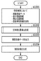
図10は、本実施例に係る画像処理装置101における一連の処理の流れを示すフローチャートである。   FIG. 10 is a flowchart illustrating a flow of a series of processes in the image processing apparatus 101 according to the present embodiment.

ステップ1001において、各取得部901〜904は、上述した視差画像データ、表示領域情報、視点位置情報、投影特性情報を、それぞれHDD204等から取得する。取得された視差画像データ及び各情報は、上述のとおり立体像位置導出部905又は投影画像生成部906に送られる。   In step 1001, each acquisition unit 901 to 904 acquires the above-described parallax image data, display area information, viewpoint position information, and projection characteristic information from the HDD 204 or the like. The acquired parallax image data and each information are sent to the stereoscopic image position deriving unit 905 or the projection image generating unit 906 as described above.

ステップ1002において、立体像位置導出部905は、受け取った視差画像データ、表示領域情報及び視点位置情報に基づいて、立体像として表示される仮想物体の位置を導出する。ここで、別フローチャートを用いて詳しく説明する。図11は、この立体像の位置を導出する処理の流れを示すフローチャートである。また、図12は、立体像の位置が導出される過程を説明する図である。   In step 1002, the stereoscopic image position deriving unit 905 derives the position of the virtual object displayed as a stereoscopic image based on the received parallax image data, display area information, and viewpoint position information. Here, it demonstrates in detail using another flowchart. FIG. 11 is a flowchart showing the flow of processing for deriving the position of this stereoscopic image. FIG. 12 is a diagram illustrating a process in which the position of a stereoscopic image is derived.

ステップ1101において、立体像位置導出部905は、視差画像データに含まれる左眼用画像と右眼用画像との間で各画素の対応付けを行う。具体的には、以下のとおりである。まず、左眼用画像gL上の注目画素(uL,vL)とその近傍画素とからなる領域画像をテンプレートとする。そして、このテンプレートを用いたパターンマッチングを右眼用画像gRに対して行い、注目画素(uL,vL)に対する右眼用画像gR上の対応画素(uR,vR)を求める。この処理を左眼用画像gL上の各画素に対して行い、全ての画素について右眼用画像gR上の画素との対応付けを行う。   In step 1101, the stereoscopic image position deriving unit 905 associates each pixel between the left eye image and the right eye image included in the parallax image data. Specifically, it is as follows. First, a region image composed of a pixel of interest (uL, vL) on the left eye image gL and its neighboring pixels is used as a template. Then, pattern matching using this template is performed on the right-eye image gR, and the corresponding pixel (uR, vR) on the right-eye image gR for the pixel of interest (uL, vL) is obtained. This process is performed for each pixel on the left-eye image gL, and all the pixels are associated with the pixels on the right-eye image gR.

ステップ1102において、立体像位置導出部905は、左眼用画像と右眼用画像との間で対応付けた画素のペア(uL,vL)と(uR,vR)について、液晶3Dディスプレイ102で表示する場合の表示画面上の画素位置を導出する。具体的には、画素位置を示す3次元座標PL(xL1,yL1,zL1)およびPR(xR1,yR1,zR1)を、次の式(3)及び式(4)に従って求める。   In step 1102, the stereoscopic image position deriving unit 905 displays the pixel pair (uL, vL) and (uR, vR) associated with the left-eye image and the right-eye image on the liquid crystal 3D display 102. In this case, the pixel position on the display screen is derived. Specifically, the three-dimensional coordinates PL (xL1, yL1, zL1) and PR (xR1, yR1, zR1) indicating the pixel position are obtained according to the following equations (3) and (4).

Figure 0006025519
Figure 0006025519

Figure 0006025519
Figure 0006025519

ここで、W及びHは表示領域情報で示される液晶3Dディスプレイ102における横及び縦のサイズ(cm)であり、Wg及びHgは視差画像における横方向と縦方向の画素数である。 Here, W and H are horizontal and vertical sizes (cm) in the liquid crystal 3D display 102 indicated by the display area information, and Wg and Hg are the number of pixels in the horizontal and vertical directions in the parallax image.

ステップ1103において、立体像位置導出部905は、ステップ1102で得られた立体表示装置の画面上の画素位置の情報とステップ1003で取得された観察者の視点位置情報とを用いて、立体像の位置を求める。具体的には、立体表示装置の画面上の画素位置を示す3次元座標PL(xL1,yL1,zL1)/PR(xR1,yR1,zR1)と、観察者の左右の眼の位置を示す3次元座標EL(xL0,yL0,zL0)/ER(xR0,yR0,zR0)とから、ELとPLとを結ぶ直線(直線EL-PL)とERとPRとを結ぶ直線(直線ER-PR)との交点P(x,y,z)を求める。この交点P(x,y,z)の座標が、視差画像間で対応付けた画素のペア(uL,vL)と(uR,vR)により形成される立体像の位置を示す頂点座標に相当する。   In step 1103, the stereoscopic image position deriving unit 905 uses the information on the pixel position on the screen of the stereoscopic display device obtained in step 1102 and the viewpoint position information of the observer acquired in step 1003 to generate a stereoscopic image. Find the position. Specifically, three-dimensional coordinates PL (xL1, yL1, zL1) / PR (xR1, yR1, zR1) indicating pixel positions on the screen of the stereoscopic display device and three-dimensional indicating positions of the left and right eyes of the observer From the coordinates EL (xL0, yL0, zL0) / ER (xR0, yR0, zR0), the straight line connecting EL and PL (straight line EL-PL) and the straight line connecting ER and PR (straight line ER-PR) Find the intersection P (x, y, z). The coordinates of this intersection P (x, y, z) correspond to the vertex coordinates indicating the position of the stereoscopic image formed by the pixel pair (uL, vL) and (uR, vR) associated between the parallax images. .

この場合において、直線EL-PLと直線ER-PRとが互いに平行である場合には、奥行きが無限遠の位置に像が形成されると見做し、後述の陰影画像生成処理の対象外とする。また、直線EL-PLと直線ER-PRとが同一平面上に存在しない場合には、2点間の距離が最小となる直線EL-PL上の点P'Lと直線ER-PR上の点P'Rを求め、これら2点の中点を2直線の交点と見做せばよい。   In this case, when the straight line EL-PL and the straight line ER-PR are parallel to each other, it is considered that an image is formed at a position where the depth is infinite, and is not subject to the shadow image generation processing described later. To do. If the straight line EL-PL and the straight line ER-PR do not exist on the same plane, the point P'L on the straight line EL-PL and the point on the straight line ER-PR that minimize the distance between the two points Find P'R and consider the midpoint of these two points as the intersection of two straight lines.

以上の処理を全ての画素のペアについて行い、立体像を構成する頂点座標群を得る。   The above processing is performed for all pixel pairs to obtain vertex coordinate groups constituting a stereoscopic image.

ステップ1104において、立体像位置導出部905は、得られた頂点座標群に公知の表面形状復元技術やテセレーション技術を適用して立体像の表面形状を推定し、立体像として表示される仮想物体の位置を特定可能なメッシュデータを生成する。   In step 1104, the stereoscopic image position deriving unit 905 applies a known surface shape restoration technique or tessellation technique to the obtained vertex coordinate group, estimates the surface shape of the stereoscopic image, and displays a virtual object displayed as a stereoscopic image. Generate mesh data that can identify the position of.

本実施例では、以上のようにして得られたメッシュデータを立体像の位置情報として用いて、陰影画像の生成がなされる。   In the present embodiment, a shadow image is generated using the mesh data obtained as described above as the position information of the stereoscopic image.

図10のフローチャートの説明に戻る。   Returning to the flowchart of FIG.

ステップ1003において、視差画像データ取得部901は、取得した視差画像のデータを液晶3Dディスプレイ102に出力する。そして、液晶3Dディスプレイ102によって、視差画像データに従った立体像が表示される。   In step 1003, the parallax image data acquisition unit 901 outputs the acquired parallax image data to the liquid crystal 3D display 102. Then, the liquid crystal 3D display 102 displays a stereoscopic image according to the parallax image data.

ステップ1004において、投影画像生成部906は、ステップ1001で取得された画像投影装置の投影特性情報及びステップ1002で生成されたメッシュデータを用いて陰影画像を生成する。陰影画像生成の詳細については、実施例1に係る図4のフローチャートのステップ403で述べたとおりである。   In step 1004, the projection image generation unit 906 generates a shadow image using the projection characteristic information of the image projection apparatus acquired in step 1001 and the mesh data generated in step 1002. Details of the shadow image generation are as described in step 403 of the flowchart of FIG. 4 according to the first embodiment.

このようにして生成された陰影画像のデータは、実施例1と同様に液晶プロジェクタ103に出力され、陰影画像データに従った仮想物体の影が現実空間の床などに投影されることになる。   The shadow image data generated in this way is output to the liquid crystal projector 103 as in the first embodiment, and the shadow of the virtual object according to the shadow image data is projected onto the floor or the like in the real space.

(その他の実施形態)
また、本発明の目的は、以下の処理を実行することによっても達成される。即ち、上述した実施形態の機能を実現するソフトウェアのプログラムコードを記録した記憶媒体を、システム或いは装置に供給し、そのシステム或いは装置のコンピュータ(またはCPUやMPU等)が記憶媒体に格納されたプログラムコードを読み出す処理である。この場合、記憶媒体から読み出されたプログラムコード自体が前述した実施の形態の機能を実現することになり、そのプログラムコード及び該プログラムコードを記憶した記憶媒体は本発明を構成することになる。
(Other embodiments)
The object of the present invention can also be achieved by executing the following processing. That is, a storage medium that records a program code of software that realizes the functions of the above-described embodiments is supplied to a system or apparatus, and a computer (or CPU, MPU, etc.) of the system or apparatus is stored in the storage medium. This is the process of reading the code. In this case, the program code itself read from the storage medium realizes the functions of the above-described embodiments, and the program code and the storage medium storing the program code constitute the present invention.

Claims (12)

視差画像を表示することにより仮想物体の立体像を観察者に知覚させる場合における、当該立体像の擬似的な影を現実空間に作成するための陰影画像を、前記仮想物体の位置及び形状を特定するデータと、前記陰影画像を現実空間に投影する画像投影手段による投影領域の位置と大きさを示す情報とに基づいて生成する、ことを特徴とする画像処理装置。   When making a viewer perceive a stereoscopic image of a virtual object by displaying a parallax image, the shadow image for creating a pseudo shadow of the stereoscopic image in the real space is specified, and the position and shape of the virtual object are specified. An image processing apparatus characterized in that the image processing apparatus generates data based on data indicating the position and size of a projection area by image projection means for projecting the shadow image onto a real space. 前記仮想物体の位置及び形状を特定するデータはメッシュデータであり、
前記画像投影手段の位置を示す点と前記画像投影手段の光軸と直交する仮想的な平面上の任意の点とを結ぶ直線が、前記メッシュデータで特定される仮想物体の表面形状を示す板状の要素と交差するかどうかを判定し、交差すると判定された場合に、当該交差する点に対応する画素を、影部分を示す画素とすることで前記陰影画像を生成する
ことを特徴とする請求項1に記載の画像処理装置。
The data specifying the position and shape of the virtual object is mesh data,
A plate in which a straight line connecting a point indicating the position of the image projecting unit and an arbitrary point on a virtual plane orthogonal to the optical axis of the image projecting unit indicates the surface shape of the virtual object specified by the mesh data It is determined whether or not to intersect with an element of a shape, and when it is determined to intersect, the shadow image is generated by setting a pixel corresponding to the intersecting point as a pixel indicating a shadow portion. The image processing apparatus according to claim 1.
前記画像投影手段と前記立体像との間に実物体が存在する場合には、当該実物体よりも前記画像投影手段に近い位置に存在する前記板状の要素に対してのみ前記交差するかどうかの判定を行うことを特徴とする請求項2に記載の画像処理装置。   If there is a real object between the image projection unit and the stereoscopic image, whether or not to intersect only with the plate-like element existing at a position closer to the image projection unit than the real object The image processing apparatus according to claim 2, wherein the determination is performed. 前記観察者の視点位置を示す情報、前記仮想物体の位置及び形状を特定するデータ及び前記視差画像を表示する立体像表示手段における表示領域のサイズを示す情報に基づいて、前記視差画像を生成する手段をさらに備えたことを特徴とする請求項1〜3のいずれか1項に記載の画像処理装置。   The parallax image is generated based on information indicating the viewpoint position of the observer, data specifying the position and shape of the virtual object, and information indicating the size of the display area in the stereoscopic image display means for displaying the parallax image. The image processing apparatus according to claim 1, further comprising means. 前記視差画像のデータを取得する手段と、
取得した前記視差画像のデータ、前記視差画像を表示する立体像表示手段における表示領域のサイズを示す情報及び前記観察者の視点位置を示す情報に基づいて、前記メッシュデータを生成する手段と、
をさらに備えたことを特徴とする請求項2又は3に記載の画像処理装置。
Means for acquiring data of the parallax image;
Means for generating the mesh data based on the acquired parallax image data, information indicating the size of the display area in the stereoscopic image display means for displaying the parallax image, and information indicating the viewpoint position of the observer;
The image processing apparatus according to claim 2, further comprising:
前記視差画像は、左眼用画像と右眼用画像とからなり、
前記メッシュデータを生成する手段は、前記左眼用画像と前記右眼用画像とを対応付け、対応付けられた画素のペアについて前記立体像表示手段の表示画面上の画素位置を導出し、導出された画素位置及び前記観察者の視点位置を示す情報から前記立体像を構成する頂点座標群を得て、得られた頂点座標群を用いて前記立体像の表面形状を推定することにより、前記メッシュデータを生成することを特徴とする請求項5に記載の画像処理装置。
The parallax image is composed of an image for the left eye and an image for the right eye,
The means for generating the mesh data associates the image for the left eye with the image for the right eye, derives a pixel position on the display screen of the stereoscopic image display means for the associated pixel pair, and derives By obtaining a vertex coordinate group constituting the stereoscopic image from the information indicating the pixel position and the observer's viewpoint position, and estimating the surface shape of the stereoscopic image using the obtained vertex coordinate group, The image processing apparatus according to claim 5, wherein mesh data is generated.
視差画像を表示することにより仮想物体の立体像を観察者に知覚させる場合における、当該立体像により生じる擬似的な集光模様を現実空間に作成するための集光模様画像を、前記仮想物体の位置、形状及び光学特性を特定するデータと、前記集光模様画像を現実空間に投影する画像投影手段による投影領域の位置と大きさを示す情報とに基づいて生成する、ことを特徴とする画像処理装置。   When making a viewer perceive a stereoscopic image of a virtual object by displaying a parallax image, a condensing pattern image for creating a pseudo condensing pattern generated by the stereoscopic image in the real space is displayed on the virtual object. An image generated based on data specifying a position, a shape, and optical characteristics, and information indicating a position and a size of a projection area by an image projecting unit that projects the condensed pattern image onto a real space. Processing equipment. 視差画像を表示することにより仮想物体の立体像を観察者に知覚させる場合における、当該立体像の擬似的な影を現実空間に作成するための陰影画像を、前記仮想物体の位置及び形状を特定するデータと、前記陰影画像を現実空間に投影する画像投影手段による投影領域の位置と大きさを示す情報とに基づいて生成する、ことを特徴とする画像処理方法。   When making a viewer perceive a stereoscopic image of a virtual object by displaying a parallax image, the shadow image for creating a pseudo shadow of the stereoscopic image in the real space is specified, and the position and shape of the virtual object are specified. An image processing method comprising: generating data based on data to be displayed and information indicating a position and a size of a projection area by an image projection unit that projects the shadow image onto a real space. 視差画像を表示することにより仮想物体の立体像を観察者に知覚させる場合における、当該立体像により生じる擬似的な集光模様を現実空間に作成するための集光模様画像を、前記仮想物体の位置、形状及び光学特性を特定するデータと、前記集光模様画像を現実空間に投影する画像投影手段による投影領域の位置と大きさを示す情報とに基づいて生成する、ことを特徴とする画像処理方法。   When making a viewer perceive a stereoscopic image of a virtual object by displaying a parallax image, a condensing pattern image for creating a pseudo condensing pattern generated by the stereoscopic image in the real space is displayed on the virtual object. An image generated based on data specifying a position, a shape, and optical characteristics, and information indicating a position and a size of a projection area by an image projecting unit that projects the condensed pattern image onto a real space. Processing method. コンピュータを請求項1〜7のいずれか1項に記載の画像処理装置として機能させるためのプログラム。   The program for functioning a computer as an image processing apparatus of any one of Claims 1-7. 請求項1〜6のいずれか1項に記載の画像処理装置と、
前記視差画像を表示する立体像表示手段と、
前記陰影画像を現実空間に投影する画像投影手段と、
を含むことを特徴とする立体像表示システム。
The image processing apparatus according to any one of claims 1 to 6,
Stereoscopic image display means for displaying the parallax image;
Image projection means for projecting the shadow image onto a real space;
A stereoscopic image display system comprising:
請求項7に記載の画像処理装置と、
前記視差画像を表示する立体像表示手段と、
前記集光模様画像を現実空間に投影する画像投影手段と、
を含むことを特徴とする立体像表示システム。
An image processing apparatus according to claim 7;
Stereoscopic image display means for displaying the parallax image;
Image projecting means for projecting the focused pattern image on a real space;
A stereoscopic image display system comprising:
JP2012255530A 2012-11-21 2012-11-21 Image processing apparatus and image processing method Active JP6025519B2 (en)

Priority Applications (1)

Application Number Priority Date Filing Date Title
JP2012255530A JP6025519B2 (en) 2012-11-21 2012-11-21 Image processing apparatus and image processing method

Applications Claiming Priority (1)

Application Number Priority Date Filing Date Title
JP2012255530A JP6025519B2 (en) 2012-11-21 2012-11-21 Image processing apparatus and image processing method

Publications (3)

Publication Number Publication Date
JP2014103599A JP2014103599A (en) 2014-06-05
JP2014103599A5 JP2014103599A5 (en) 2016-01-07
JP6025519B2 true JP6025519B2 (en) 2016-11-16

Family

ID=51025716

Family Applications (1)

Application Number Title Priority Date Filing Date
JP2012255530A Active JP6025519B2 (en) 2012-11-21 2012-11-21 Image processing apparatus and image processing method

Country Status (1)

Country Link
JP (1) JP6025519B2 (en)

Family Cites Families (5)

* Cited by examiner, † Cited by third party
Publication number Priority date Publication date Assignee Title
JPH0664621B2 (en) * 1986-09-25 1994-08-22 工業技術院長 Image generation method
JP3579162B2 (en) * 1995-06-29 2004-10-20 松下電器産業株式会社 3D CG image generation device
JP3387856B2 (en) * 1999-08-06 2003-03-17 キヤノン株式会社 Image processing method, image processing device, and storage medium
JP2003187264A (en) * 2001-12-17 2003-07-04 Denso Corp Image display device
JP2010055131A (en) * 2008-07-28 2010-03-11 Namco Bandai Games Inc Program, information storage medium, and image generation system

Also Published As

Publication number Publication date
JP2014103599A (en) 2014-06-05

Similar Documents

Publication Publication Date Title
US10506223B2 (en) Method, apparatus, and device for realizing virtual stereoscopic scene
TWI531212B (en) System and method of rendering stereoscopic images
KR102049456B1 (en) Method and apparatus for formating light field image
EP3591966B1 (en) Image processing apparatus, image processing method, and program
AU2018249563B2 (en) System, method and software for producing virtual three dimensional images that appear to project forward of or above an electronic display
TWI786157B (en) Apparatus and method for generating a tiled three-dimensional image representation of a scene
CN102905145B (en) Stereoscopic image system, image generation method, image adjustment device and method thereof
WO2015196791A1 (en) Binocular three-dimensional graphic rendering method and related system
US8866887B2 (en) Computer graphics video synthesizing device and method, and display device
WO2018032841A1 (en) Method, device and system for drawing three-dimensional image
JP2020173529A (en) Information processing device, information processing method, and program
JP2011164781A (en) Stereoscopic image generation program, information storage medium, apparatus and method for generating stereoscopic image
EP2904581A1 (en) Method and apparatus for determining a depth of a target object
US9225968B2 (en) Image producing apparatus, system and method for producing planar and stereoscopic images
JP5712737B2 (en) Display control apparatus, display control method, and program
CA3155612A1 (en) Method and system for providing at least a portion of content having six degrees of freedom motion
JP6025519B2 (en) Image processing apparatus and image processing method
WO2017191703A1 (en) Image processing device
JP5868055B2 (en) Image processing apparatus and image processing method
KR100893381B1 (en) Methods generating real-time stereo images
TWI812548B (en) Method and computer device for generating a side-by-side 3d image
JP2014135006A (en) Image processing system, image processing method and program
CN111754558B (en) Matching method for RGB-D camera system and binocular imaging system and related system thereof
US20220044351A1 (en) Method and system for providing at least a portion of content having six degrees of freedom motion
Chen et al. A View-Dependent Stereoscopic System Using Depth-Image-Based Tracking

Legal Events

Date Code Title Description
A521 Written amendment

Free format text: JAPANESE INTERMEDIATE CODE: A523

Effective date: 20151111

A621 Written request for application examination

Free format text: JAPANESE INTERMEDIATE CODE: A621

Effective date: 20151111

A977 Report on retrieval

Free format text: JAPANESE INTERMEDIATE CODE: A971007

Effective date: 20160822

TRDD Decision of grant or rejection written
A01 Written decision to grant a patent or to grant a registration (utility model)

Free format text: JAPANESE INTERMEDIATE CODE: A01

Effective date: 20160913

A61 First payment of annual fees (during grant procedure)

Free format text: JAPANESE INTERMEDIATE CODE: A61

Effective date: 20161011

R151 Written notification of patent or utility model registration

Ref document number: 6025519

Country of ref document: JP

Free format text: JAPANESE INTERMEDIATE CODE: R151