JP6025337B2 - Ink tank - Google Patents
Ink tank Download PDFInfo
- Publication number
- JP6025337B2 JP6025337B2 JP2012022294A JP2012022294A JP6025337B2 JP 6025337 B2 JP6025337 B2 JP 6025337B2 JP 2012022294 A JP2012022294 A JP 2012022294A JP 2012022294 A JP2012022294 A JP 2012022294A JP 6025337 B2 JP6025337 B2 JP 6025337B2
- Authority
- JP
- Japan
- Prior art keywords
- light
- ink tank
- ink
- guide member
- light guide
- Prior art date
- Legal status (The legal status is an assumption and is not a legal conclusion. Google has not performed a legal analysis and makes no representation as to the accuracy of the status listed.)
- Active
Links
Images


Classifications
-
- B—PERFORMING OPERATIONS; TRANSPORTING
- B41—PRINTING; LINING MACHINES; TYPEWRITERS; STAMPS
- B41J—TYPEWRITERS; SELECTIVE PRINTING MECHANISMS, i.e. MECHANISMS PRINTING OTHERWISE THAN FROM A FORME; CORRECTION OF TYPOGRAPHICAL ERRORS
- B41J2/00—Typewriters or selective printing mechanisms characterised by the printing or marking process for which they are designed
- B41J2/005—Typewriters or selective printing mechanisms characterised by the printing or marking process for which they are designed characterised by bringing liquid or particles selectively into contact with a printing material
- B41J2/01—Ink jet
- B41J2/17—Ink jet characterised by ink handling
- B41J2/175—Ink supply systems ; Circuit parts therefor
- B41J2/17566—Ink level or ink residue control
- B41J2002/17573—Ink level or ink residue control using optical means for ink level indication
Landscapes
- Ink Jet (AREA)
Description
本発明はインクタンクに関する。 The present invention relates to an ink tank.
近年、インクジェット記録装置において記録画像の高画質化の要求から従来の4色(ブラック、イエロー、マゼンタ、シアン)インクに、濃度の薄い淡色マゼンタ、淡色シアンといったインクが使われるようになってきており、さらにはレッド、ブルーインクといったいわゆる特色インクの使用も提案されてきている。このような場合、インクジェット記録装置に対しては7〜8個といったインクタンクを個別に搭載することになって、誤った装着位置へインクタンクを搭載する可能性が高くなってしまう。このような誤った装着位置へのインクタンクの搭載を防止するために、記録装置の本体側が個々のインクタンクの位置認証を行って誤装着を報知するものとして、例えば、次のようなものが知られている。 In recent years, inks such as light-colored magenta and light-colored cyan having a low density have been used for conventional four-color (black, yellow, magenta, and cyan) inks due to the demand for higher image quality of recorded images in inkjet recording apparatuses. Furthermore, the use of so-called special color inks such as red and blue inks has been proposed. In such a case, 7 to 8 ink tanks are individually mounted on the ink jet recording apparatus, and there is a high possibility that the ink tank is mounted at an incorrect mounting position. In order to prevent the ink tank from being mounted at such an incorrect mounting position, the main body side of the recording apparatus performs position authentication of each ink tank and notifies the erroneous mounting. Are known.
記録装置の本体側の電気接点(コネクタ)と接続するインクタンクの接点(パッド)を介して入力される信号と、インクタンク自身が有する個体情報とに基づいて、発せられた信号に対して合致する固体情報を有するインクタンクのみが発光する。このようなインクタンクを特定した発光制御が可能な記録装置において、キャリッジに搭載された複数のインクタンクを該キャリッジの移動に伴って所定の位置で順次発光させる。そのような所定のタイミングにおいて所定の位置で発光される光を検出することで位置認証を行い、発光が検出されないインクタンクは誤った位置に搭載されていると認識してユーザに報知する、というものである。また、インクタンクの装着位置に関する情報だけでなく、インクタンク内のインク残量などに関する情報もユーザに認識させておくことが望ましい。 Matches the generated signal based on the signal input through the contact (pad) of the ink tank connected to the electrical contact (connector) on the main body side of the printing apparatus and the individual information of the ink tank itself Only ink tanks having solid information to emit light. In such a recording apparatus capable of controlling light emission by specifying an ink tank, a plurality of ink tanks mounted on the carriage are sequentially caused to emit light at predetermined positions as the carriage moves. The position authentication is performed by detecting the light emitted at the predetermined position at such a predetermined timing, and the user is notified that the ink tank in which the light emission is not detected is mounted at the wrong position. Is. It is also desirable for the user to recognize not only information related to the ink tank mounting position but also information related to the remaining amount of ink in the ink tank.
従来は、上述したようなインクタンクの状態に関する情報をインクジェット記録装置に接続されたパーソナルコンピュータ(PC)に転送し、PCのモニタに表示することによりユーザへの報知を行っていた。しかしながら、近年、デジタルカメラの普及に伴って、PCを介さずにデジタルカメラと記録装置としてのインクジェット記録装置とを直接接続して印刷する用途(ノンPC記録)が増えつつある。ノンPC記録を行う場合は、インクジェット記録装置の本体にディスプレイを設け、それらの情報を表示することが考えられる。しかしながら、ディスプレイを設けることで、コストアップやインクジェット記録装置の大型化につながるだけでなく、インクジェット記録装置のデザイン等にも影響を及ぼすことになるので、ディスプレイを設けることは必ずしも好ましいことではない。 Conventionally, information regarding the state of the ink tank as described above is transferred to a personal computer (PC) connected to the ink jet recording apparatus and displayed on a monitor of the PC to notify the user. However, in recent years, with the widespread use of digital cameras, applications (non-PC recording) in which a digital camera and an inkjet recording apparatus as a recording apparatus are directly connected without using a PC are increasing. When performing non-PC recording, it is conceivable to provide a display on the main body of the ink jet recording apparatus to display the information. However, providing a display not only increases costs and increases the size of the ink jet recording apparatus, but also affects the design of the ink jet recording apparatus and so on, so it is not always preferable to provide a display.
そこで、インクタンクに関する情報をインクタンク自身が光って光情報として報知するものとして、光情報として発光制御された光をインクタンクに据え付ける導光部材を介してユーザ視認性の高い位置まで導光して表示させるものが知られている。 Therefore, the information related to the ink tank is emitted as light information by the ink tank itself, and the light whose emission is controlled as light information is guided to a position with high user visibility through a light guide member installed on the ink tank. What is displayed is known.
特許文献1には、先に述べたようなインクタンクの位置認証を行って誤装着防止の機能を有するもので、装着位置およびインク残量などのインクタンクに関する情報を導光部材を介して光情報としてユーザに報知するインクタンクが記載されている。 Japanese Patent Application Laid-Open No. 2004-260688 has a function of preventing the erroneous mounting by performing the position authentication of the ink tank as described above. Information on the ink tank such as the mounting position and the remaining amount of ink is transmitted through the light guide member. An ink tank to be notified to the user as information is described.
導光部材の一部をもって形成されるユーザ報知のための光情報を発する表示部は、ユーザがあらゆる角度から眺めることを想定した場合において視認可能なように、光を拡散させるような加工が施される。このために、表示部から出射される光は指向性が低い広がりを有した光となることが望まれる。 The display unit that emits optical information for user notification formed by a part of the light guide member is processed to diffuse light so that it can be visually recognized when the user assumes viewing from all angles. Is done. For this reason, it is desired that the light emitted from the display unit is light having a spread with low directivity.
一方で、個々のインクタンクの位置認証は、先述したように、キャリッジに搭載された複数のインクタンクについて、順次、各々のインクタンクの発光部を発光させて所定の位置から発せられるインクタンクの個体情報を載せた光を検出することにより行われる。そのために、インクタンクの個体情報を載せた位置認証のための光は、誤った位置に装着されていた場合においては、その位置で発せられる光が受光部にて検出されないように指向性が高い光であることが望まれる。指向性が低い拡散された光では、誤った位置に装着されたインクタンクから発せられた光が受光部に受光されてしまって誤装着されているとエラー認識されなくなる可能性があるからである。 On the other hand, as described above, the position authentication of each ink tank is performed for each of the plurality of ink tanks mounted on the carriage by sequentially emitting light from the light emitting portions of the respective ink tanks. This is done by detecting light carrying individual information. Therefore, the light for position authentication on which the individual information of the ink tank is placed has high directivity so that the light emitted at that position is not detected by the light receiving unit when it is mounted at the wrong position. It is desired to be light. This is because, in diffused light with low directivity, light emitted from an ink tank mounted at an incorrect position may be received by the light receiving unit and may not be recognized as an error if it is mounted incorrectly. .
このように、ユーザに対して情報を報知するための表示部から出射される光と、位置認証のために出射される光は、より好ましいと望まれる出射形態が相反するものである。 As described above, the light emitted from the display unit for notifying the user of the information and the light emitted for the position authentication conflict with each other in the desired emission form.
しかしながら、特許文献1に記載のインクタンクは、インクタンクの状態に関する情報をユーザに報知するための表示部から出射される拡散された光を、本体側の受光部がインクタンクの個体情報を載せた光として受光して位置認証を行うものである。そのために、誤装着されたインクタンクの光も受光部が受光してエラーを認識できないことが起こり得るなどの課題を有していた。このように、ユーザ報知のための表示部と位置認証のための光の出射部を兼ねる形態のインクタンクは、各々に望まれる出射形態のいずれかを選択しなければならず、相反する要求を共に両立させることが困難なものであった。
However, in the ink tank described in
このような位置認証のための光とユーザ報知のための光とを共に出射するインクタンクにおいて、各々に望まれる出射形態を両立させて、誤装着防止の信頼性が高く、ユーザ視認性が高い報知を可能とするインクタンクを提供することが本願発明の目的である。 In such an ink tank that emits both the light for position authentication and the light for user notification, it is possible to achieve both the emission forms desired for each, high reliability for preventing erroneous mounting, and high user visibility. It is an object of the present invention to provide an ink tank that enables notification.
本願発明のインクタンクは、発光部と、該発光部から発光される光を導光するための導光部と、を具えたインクタンクであって、前記導光部は透光性の導光部材を具え、前記導光部材は、導光された前記インクタンクの装着位置に関する位置認証のための光を出射する出射面と、前記出射面に対向する対向面と、前記出射面及び対向面と異なる側面に形成されてなる、導光された光を出射して前記インクタンクの状態に関する情報を表示するための表示面と、を有し、前記発光部は、前記インクタンクの底面に対して略平行な一面に設けられて、前記出射面は、該一面に対して略平行に形成されて前記インクタンクの上方へ光を出射することを特徴とする。 The ink tank of the present invention is an ink tank comprising a light emitting part and a light guiding part for guiding light emitted from the light emitting part, wherein the light guiding part is a light-transmissive light guide. The light guide member includes a light exit surface that emits light for position authentication relating to the mounting position of the light guided ink tank, a counter surface that faces the light output surface, and the light output surface and the counter surface. And a display surface for emitting guided light and displaying information on the state of the ink tank, wherein the light emitting unit is formed on the bottom surface of the ink tank. The emission surface is formed substantially parallel to the one surface and emits light upward of the ink tank .
本発明の構成によれば、インクタンクの位置認証を行うための光と、インク残量などのインクタンクの情報をユーザに報知するための光とを分離することができるために、各々の用途に応じた光の出射形態で出射することを可能とする。ひいては、誤装着防止の信頼性が高く、インクタンクの状態に関する情報報知のユーザ視認性が高いインクタンクを提供することが可能となる。 According to the configuration of the present invention, it is possible to separate the light for performing the position authentication of the ink tank and the light for notifying the user of the ink tank information such as the ink remaining amount. It is possible to emit light in the form of light emission according to. As a result, it is possible to provide an ink tank with high reliability for preventing erroneous mounting and high user visibility of information notification regarding the state of the ink tank.
以下、図面を参照して本発明の実施形態を詳細に説明する。 Hereinafter, embodiments of the present invention will be described in detail with reference to the drawings.
(実施形態)
図1は本発明の実施形態に係るインクタンクの外観の一例を示した図で、図1(a)はインクタンクの上面図、図1(b)はインクタンクの側面図、図1(c)はインクタンクの正面図、図1(d)はインクタンクの底面図である。なお、本願明細書においては、図7に示すインクジェット記録装置200(以下、プリンタ200と記載する。)においてユーザ300に近い側を「正面」側、給紙部202に近い側を「背面」側とする。すなわち、プリンタ200に装着されるインクタンク(1K、1C、1M、1Y)が有する4つの側面では、ユーザ300に対向する側面を「正面」側の側面、給紙部202に対向する側面を「背面」側の側面とする。また、「上方」および「下方」とするのは、プリンタ200にインクタンクを装着した際の鉛直方向に沿った方向における上下方向である。
(Embodiment)
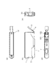
FIG. 1 is a view showing an example of the appearance of an ink tank according to an embodiment of the present invention. FIG. 1 (a) is a top view of the ink tank, FIG. 1 (b) is a side view of the ink tank, and FIG. ) Is a front view of the ink tank, and FIG. 1D is a bottom view of the ink tank. In the present specification, in the ink jet recording apparatus 200 (hereinafter referred to as the printer 200) shown in FIG. 7, the side close to the
図1において、本実施形態のインクタンク1は正面側の側面下部で支持される支持部材3を有している。支持部材3はインクタンク1の外装と同一材料で一体成型で形成されており、後述するタンクホルダへの装着の際に撓んで弾性変形することでタンクホルダの係止部と係合可能となる。インクタンク1の背面側の側面および支持部材3には、タンクホルダの係止部にそれぞれ係合可能な第1係合部5および第2係合部6が各々設けられ、これらとタンクホルダの係止部とが係合することによってインクタンク1がタンクホルダへ装着される。インクタンク1の底面には、タンクホルダへの装着時に、後述する記録ヘッドのインク導入口と結合してインク供給を行うためのインク供給口7が設けられている。
In FIG. 1, an
図2は本実施形態に係るインクタンクの分解斜視図であり、インクタンク1を構成する個々の部材を示している。インクタンク1は上面が開口された筐体11の正面側に導光部材に導光部材20を圧入するかたちで挿入して固定し、蓋部材13を筐体11に超音波溶着することによって固定している。インクタンク1の底面には後述するLEDなどの発光部101を有した基板100が取り付けられている。導光部材20は、発光部101から発光された光を導光するための透光性の部材である。このような導光部材20に導光された光をプリンタ内の受光部へ出射するための出射面22、導光された光を反射するための出射面22に対して傾斜して形成される反射面24と、反射面24で反射された光を出射して情報を表示するための表示面23と、を有する。導光部材20は反射面24を有することで、図3に示すように、発光された光が直進する光路(点線矢印B)上に形成される側面(出射面22)と異なる側面(表示面23)へ光を分岐させて焦光し、十分な光量の光を表示面23から出射させることを可能とする。
FIG. 2 is an exploded perspective view of the ink tank according to the present embodiment, and shows individual members constituting the
蓋部材13には正面側に切り欠き部14があり、導光部材20の出射面22と切り欠き部14により図1(a)に示すような出射部32が形成されて発光部からの光を本体側の受光部210へ出射する。また、筐体11の正面側にも切り欠き部12があり、後述する導光部材20の表示面23と切り欠き部12により図1(c)に示すような表示部33が形成されて発光部101からの光をユーザへ出射する。出射部32から出射されて本体側の受光部210へ受光される光はインクタンクの個体情報を載せた位置認証のための光であって、収納するインクの色情報を含むインクタンクの識別情報である。このように、本願明細書において「インクタンクの個体情報を投光するための出射部」とするのは、インクタンクの装着位置に関する位置認証のための光を出射する部位を意味する。また、「インクタンクの状態に関する情報を表示するための表示部」とするのは、ユーザにインク残量などのインクタンクの状態に関する情報を報知するための光を出射する部位を意味する。
The
このように本実施形態の導光部は、インクタンクの個体情報を載せた位置認証を行うための光と、インク残量などのインクタンクの情報をユーザに報知するための光とを分離して出射するものである。これによって、ユーザ視認性が高くなるように表示部33では光を拡散させて出射する一方で、インクジェット記録装置の本体側の受光部に対して指向性が高くなるように出射部32では光を絞って出射する、といったように、各々の好ましい出射形態で光を出射させることができる。そのために、表示部33と出射部32との相反する好ましい出射形態を両立させて、信頼性の高い誤装着防止のための位置認証およびユーザ視認性の高い情報報知が可能となる。
As described above, the light guide unit of the present embodiment separates the light for performing the position authentication on which the individual information of the ink tank is placed and the light for notifying the user of the ink tank information such as the ink remaining amount. Are emitted. Accordingly, the
なお、本実施形態の導光部は筐体11に形成された空間に導光部材20を挿入することで形成されるが、本発明の導光部はこのような実施形態に限られない。例えば、導光部材20が挿入される「空間」を導光部として、発光部101からの光を蓋部材13形成された切り欠き部14から光を出射するとともに筐体11の正面側側面に形成された切り欠き部12から光を出射するもので光を分離して出射するようなものでもよい。
In addition, although the light guide part of this embodiment is formed by inserting the
図3は本実施形態のインクタンクをタンクホルダに装着した状態の断面図である。図3(a)に示すように、タンクホルダ150に装着されたインクタンク1は、インクタンク1の背面側の第1係合部5がタンクホルダ150の係止部155と係合し、インクタンク1の正面側の第2係合部6がタンクホルダ150の係止部156と係合した状態となって固定される。このようにタンクホルダ150に装着されるインクタンク1の発光手段となるLEDなどの発光部101が設けられる基板は導光部材20の下方に位置する。点線矢印Aで示す第一の光路Aは、発光部101から発光された光の一部が導光部材20の内部へ入光したのち反射面24で反射されて表示面23から出射された光が表示部33を介して外部へ出射される光の様子を示す。また、点線矢印Bで示す第二の光路Bは、発光部101から発光された光の一部が導光部材20の内部へ入光したのち直進して出射面から出射された光が出射部32を介して外部へ出射される光の様子を示す。ユーザ300は第一の光路Aを経由した光が表示部33から出射されたものを視認して情報を認識し、本体側に固定された受光部210は第二の光路Bを経由した光が出射部32から出射されたものを受光して位置認証を行う。
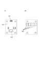
FIG. 3 is a cross-sectional view showing a state where the ink tank of this embodiment is mounted on the tank holder. As shown in FIG. 3A, in the
また、インクタンクの個体情報を載せた位置認証のための光を出射する出射面22およびユーザ視認のための光を出射する表示面23はそれらが逆の配置であっても構わない。すなわち、正面側から出射される光で位置認証し、上方へ出射された光でユーザが視認するものでも構わない。
Further, the
本願明細書における「インクタンクの情報」とは、インクタンクの装着状態の良否(すなわち装着が完全であるか否か)、装着位置の適否(インク色に対応して予め定められているタンクホルダ上の装着位置に正しく装着されているか否か)、さらにはインク残量の有無(十分なインク量が残っているか否か)などであり、発光部からの発光の有無や発光の状態(点滅など)によりそれらの情報の提示が可能となるものである。 In the specification of the present application, “ink tank information” refers to whether or not the ink tank is mounted (that is, whether or not the mounting is complete), whether or not the mounting position is appropriate (a tank holder determined in advance corresponding to the ink color) Whether or not it is correctly installed at the upper mounting position), and whether or not there is a remaining amount of ink (whether or not a sufficient amount of ink remains). Such information can be presented.
表示面23から出射された光は、広範囲の角度から視認可能であることが必要なため、その表面を粗くして該表面の凹凸により散乱させて光の出射領域を広げるようにすることが望ましい。特に、導光部材20に対してポリスチレンやポリカーボネイト等の光透過性に優れた材料を使用する場合には、点線矢印Aで示すような出射面となる表示面23に対して略垂直に進行する光以外は該出射面で全反射してしまうために、ある一定の角度以外で光を視認できなくなってしまう。そのために、このような材料を用いる際には特に、出射面を出射した光を表示面23で拡散させて広い角度に光を放つことが有効となる。
Since the light emitted from the
表面を粗くするための具体的な方法としては梨地加工やシボ加工などが挙げられる。特に、シボ加工は表面に微細な凹凸パターンを刻印して光が放射状に均一拡散することを可能にするために好ましい。 Specific methods for roughening the surface include satin processing and embossing. In particular, embossing is preferable in order to engrave a fine concavo-convex pattern on the surface and allow light to uniformly diffuse radially.
また、表示面23の寸法および形状を適宜調整することでも、光の出射領域について十分な広がりを確保することができる。例えば、表示面23を図3においてユーザ300に向かって凸型の曲面を形成するように調整する。導光部材の内部から空気層へそのような曲面を界面として出射する際には、出射角度が拡大されて出射するために光が拡散される。
In addition, by appropriately adjusting the size and shape of the
さらには、表示部33を形成するインクタンク1の側面の筐体11の正面側にも切り欠き部12の寸法および形状を調製することで光の出射領域を広げるようにしてもよく、以上のような出射領域を広げるための加工および調整は、適宜行うことができる。
Furthermore, the light emission area may be expanded by adjusting the size and shape of the
また、図に示すように、本実施形態の導光部材20の入射部31および出射部32は、基板100に対して略垂直方向に沿って配置されている。さらに、導光部材20はその下端部において、発光部101が設けられる基板100に対して略平行な入射面21を有し、その上端部において、該入射面21に略平行な出射面22を有する。このように発光部101から略垂直方向に沿って配置される、発光部101が設けられる一面、入射面21、出射面22の3つの面が略平行に形成されることで、発光部101からの光の利用効率を著しく高めることができる。この理由として、一般に、LEDなどの発光部から放射状に発光される光は、該発光部が設けられる面に対して略垂直な方向へ進行する垂直光の光量が最も多くなることが挙げられる。またその他の理由として、略垂直な方向に進行する光を除くと異なる媒体の界面を透過する際に一部の光が透過せずに反射することで光量が減衰すること、なども挙げられる。すなわち、本実施形態のインクタンク1は、発光部を設ける面と導光部材の入射面と導光部材の出射面とを一律に水平とすることで、このように光の利用効率を高めて光量の低いLEDや大きな駆動電力をかけられない発光部であっても発光手段として使用することを可能にする。
Moreover, as shown in the drawing, the
図3(b)に示すように、導光部材20は入射面21を支持する筐体11の一部によって被覆されて発光部101から発光される光の一部を遮断して矢印幅dで入射可能とする入射部31を形成する。また、本実施形態のインクタンクは、入射部31が有する入射面積よりも出射部32が有する出射面積を小さく設定している。
As shown in FIG. 3B, the
このように出射部32の出射面積を小さく設定することで、導光部材に入光した光を出射部32に集光させてより密度の高い光を出射させることが可能となる。そのために、出射部32から出射される光の光量の確保ができると共に指向性が向上し、正しい装着位置と誤った装着位置での光量差が大きくなって誤装着検知の精度が向上する。
Thus, by setting the emission area of the
また、入射部31は発光部101に近接して配置されることが望ましい。これは、導光部材20に入射できる光の光量は発光部101と入射部31との距離の二乗に反比例するために、近接させることで発光部101から発光された光を漏らさずに導光部材20へ入光させて利用効率を向上させるためである。
Further, it is desirable that the
図3(a)に示すように、インクタンク1の内部は、正面側に位置してインクを収納するインク収納室1100と、背面側に位置してインク供給口7に連通する負圧発生部材収納室120とに分割され、両者は連通部130を介して接続されている。インク収納室1100にはインクがそのまま貯留される一方、負圧発生部材収納室120には、インクを含浸保持するスポンジや繊維集合体等のインク吸収体(以下、便宜的に多孔質部材と示す)が設けられている。この多孔質部材は、記録ヘッドのインク吐出用のノズル部に形成されるメニスカスの保持力と平衡してインク吐出部からのインク漏れを抑止するに十分で、かつ記録ヘッドのインク吐出動作が可能な範囲にある適切な負圧を発生するためのものである。
As shown in FIG. 3A, the interior of the
負圧発生部材収納室120は、いずれも上記したようなインク吸収体からなる第1のインク吸収体(最上部のインク吸収体)、第2のインク吸収体(中央のインク吸収体)、第3のインク吸収体(最下部のインク吸収体)が圧入されて構成される。これらのインク吸収体の毛管力の強さは、(最上部のインク吸収体の毛管力の強さP1)<(中央のインク吸収体の毛管力の強さP2)<(最下部のインク吸収体の毛管力の強さP3)となっている。
Each of the negative pressure generating
また、第3のインク吸収体(最下部のインク吸収体)と第2のインク吸収体(中央のインク吸収体)との吸収体界面が連通部130を分割する高さ位置に形成される。
In addition, an absorber interface between the third ink absorber (lowermost ink absorber) and the second ink absorber (center ink absorber) is formed at a height position where the
負圧発生部材収納室に収納されるインク吸収体がこのような構成となることで、該連通部130を介しての気液交換のためのエア流路および液体流路を確実に担保し、且つ、インク吸収体に保持されるインクの液面回復を良好に行うことが可能となる。
Since the ink absorber accommodated in the negative pressure generating member accommodating chamber has such a configuration, the air flow path and the liquid flow path for gas-liquid exchange through the
なお、インクタンク1の内部構成は、このような多孔質部材の収納室とインクをそのまま貯留する収納室とに分ける形態に限られない。例えば、多孔質部材がインクタンク内部空間の実質的に全体に充填されるものでもよい。また、負圧発生手段として多孔質部材を用いるのではなく、容積を拡張する方向に張力を発生するゴム等の弾性材料で形成した袋状部材内にインクをそのまま充填し、この袋状部材が発生する張力によって内部のインクに負圧を作用するようにしたものでもよい。さらには、インク収容空間の少なくとも一部を可撓性部材で構成し、その空間内にインクだけを収容するとともに、可撓性部材にばね力を作用させることで負圧を発生させるようにしたものでもよい。
The internal configuration of the
インク収納室110の底部には、インクタンク1の装置への装着時において装置側に設けられたインク残量検出用センサと対向可能な部位に、不図示の被検出部が設けられている。本実施形態において、インク残量検出用センサは発光素子および受光素子を有する光センサである。また、被検出部は、透明もしくは半透明な材質からなり、かつインク非収納時には適切に発光素子からの光を反射させて受光素子に戻すことができるように形状、角度等が定められた斜面部を有したプリズム状のものである。
At the bottom of the
負圧発生部材収納室120の上面には、記録ヘッドへのインク供給に伴って増大する負圧を緩和し、これを好ましい所定範囲に維持すべく外気を導入するための不図示の大気連通部が設けられている。
On the upper surface of the negative pressure generating
図4は基板の内側表面および外側表面の様子を示した図である。図4(a)は基板100の、インクタンクに取り付けられた際に外部に露出しない内側表面の様子を示しており、LEDなどの可視光を含む光を発光する発光部101と発光部101を制御するための制御素子103とが設けられている。図4(b)は基板100の、インクタンクに取り付けられた際に外部に露出する外側表面の様子を示しており、本体側の電気接点とコンタクトするための複数の電極パッド102が配置されている。発光部101を制御する制御素子103は、本体側から電極パッド102を介して供給される電気信号により発光部101の発光の制御を行う。電極パッド102は、図3(b)に示すようにインクタンク1がタンクホルダ150に固定された状態において、タンクホルダ150に設けられた電気接点152と、インクタンク1に設けられた基板100の外側表面に設けられた電極パッド102とが接触することでインクタンク1と本体側との間で電気接続が可能となる。
FIG. 4 is a view showing a state of the inner surface and the outer surface of the substrate. FIG. 4A shows the state of the inner surface of the
図5は本実施形態の導光部材の外観を示した図である。図5(a)は導光部材の上面図、図5(b)は導光部材の側面図、図5(c)は導光部材の正面図、図5(d)は導光部材の底面図である。 FIG. 5 is a view showing the appearance of the light guide member of this embodiment. 5A is a top view of the light guide member, FIG. 5B is a side view of the light guide member, FIG. 5C is a front view of the light guide member, and FIG. 5D is a bottom view of the light guide member. FIG.
図5(b)に示すように、導光部材20はその上面に出射面22、正面側の側面に表示面23、表示面23と対向して位置する側面に出射面22に対して傾斜した反射面24を形成する。このように、出射面22に隣接する面が傾斜して反射面24を形成することで、図3(a)に示すように、光路Aにおける反射面24で反射して屈曲するまでの光路は、発光部101が設けられる基板100に対する略垂直方向より僅かに傾いているが略垂直方向となる。これにより、先述したような垂直方向の光の光量が最も大きくなる性質を利用して、位置認証のための光路Bと分離されるユーザへの情報報知のための光路Aにおける光に関しても、利用効率が高く、より光量を保持したものを利用することができる。
As shown in FIG. 5B, the
図5(b)に示されるように、導光部材20は入射面21から反射面24にかけて、入射面21から反射面24の端部24aまで水平方向での断面積が徐々に増大するように傾斜する傾斜面26、27を有している。このような傾斜面を有することで得られる効果について、図8の導光部材の摸式図を用いて説明する。
As shown in FIG. 5B, the
図8(a)は、導光部材20´の水平方向での断面積が縮小する方向に側面が傾斜した場合を説明するための図である。発光部101´から発光される光のうち、基板100に対して略垂直方向に進行する光は直進するが、点線矢印で示す角度αをもって略垂直方向以外の方向に進行する光は傾斜面26´、27´によって光の角度が水平方向に近づく反射を繰り返して上方へ進行する。一方、図8(b)で示したように導光部材20´の断面積が増大する方向に傾斜面が傾斜していた場合は、略垂直方向以外の方向に進行する光は、傾斜面26´、27´によって反射されて略垂直方向に近い角度をもって最小限の反射回数で上方に到達する。したがって、導光部材の水平方向での断面積が増大する方向に傾斜面を傾斜させることで、導光部材の側面で反射することによって減衰される発光部101´の光の光量を十分に確保して効率よく出射部へ導光することが可能となる。
FIG. 8A is a diagram for explaining a case where the side surface is inclined in a direction in which the cross-sectional area in the horizontal direction of the
図6は、本実施形態のインクタンクを装着して記録を行うプリンタの外観を示す図であり、図7は、図6に示すプリンタの本体カバーを開放した状態を示す斜視図である。 FIG. 6 is a view showing the appearance of a printer that performs recording with the ink tank of the present embodiment installed, and FIG. 7 is a perspective view showing a state in which the main body cover of the printer shown in FIG. 6 is opened.
本実施形態のプリンタ200は、記録ヘッドおよびインクタンクを搭載したキャリッジが走査して記録を行う機構などが、本体カバー201およびその他の筐体部分によって覆われているプリンタ本体と、その前後にそれぞれ設けられる排紙トレイ203と、自動給紙装置(ASF)202とを備えたものである。また、本体カバーを閉じた状態および開いた状態の両方で本プリンタの状態を表示するための表示器、電源スイッチおよびリセットスイッチを備えた操作部213が設けられている。
The
本体カバー201を開放した状態では、図7に示すように、ユーザは、記録ヘッドユニット105およびインクタンク1K、1Y、1M、1C(以下では、これらのインクタンクを同一の符号「1」で示す場合もある)を搭載したキャリッジ205が移動する範囲およびその周辺を見ることができる。実際は、本体カバー201を開けると、キャリッジ205が自動的に同図に示すほぼ中央の位置(以下、「タンク交換位置」ともいう)へ移動するシーケンスが実行され、ユーザは、このタンク交換位置でそれぞれのインクタンクの交換操作などを行うことができる。
In the state in which the
本実施形態のプリンタ200は、記録ヘッドユニット105に各色のインクに対応したチップ形態の記録ヘッド(不図示)が設けられ、これら各色の記録ヘッドがキャリッジ205の移動によって用紙などの記録媒体に対して走査を行い、この走査の間に記録媒体にインクを吐出して記録を行うものである。すなわち、キャリッジ205は、その移動方向に延在するガイド軸207と摺動可能に係合するとともに、キャリッジモータおよびその伝動機構によって、上述の移動をすることができる。そして、K、Y、M、Cのインクに対応したそれぞれの記録ヘッドでは、フレキシブルケーブル206を介して本体側の制御回路から送られる吐出データに基づいてインク吐出が行われる。また、紙送りローラや排紙ローラなどの紙送り機構が設けられ、給紙部202から給紙された記録媒体(不図示)を排紙トレイ203まで搬送することができる。また、キャリッジ205には、インクタンクホルダを一体に備えた記録ヘッドユニット105が着脱自在に装着され、一方、この記録ヘッドユニット105に対してそれぞれのインクタンク1が着脱自在に装着される。
In the
記録動作に際しては、記録ヘッドが上記の移動によって走査しその間にそれぞれの記録ヘッドから記録媒体にインクを吐出して記録ヘッドにおける吐出口配列範囲(記録ヘッド主走査方向に直交する方向)に対応した有効幅の領域に記録を行うとともに、この走査と次の走査の間に、上記紙送り機構によって上記幅またはそれ未満の所定量の紙送りを行うことにより、記録媒体に対して順次記録を行ってゆく。また、上記のキャリッジ移動による記録ヘッドの移動範囲の端部には、各記録ヘッドについてその吐出口が配設された面を覆うキャップなどの吐出回復ユニットが設けられている。これにより、記録ヘッドは所定の時間間隔で回復ユニットが設けられた位置へ移動して、予備吐出などの回復処理を行う。 During the recording operation, the recording head is scanned by the above movement, and ink is ejected from the respective recording heads to the recording medium during that time to correspond to the ejection port array range (direction orthogonal to the recording head main scanning direction) in the recording head. In addition to recording in the effective width area, recording is performed sequentially on the recording medium by feeding a predetermined amount of paper of the width or less by the paper feed mechanism between this scan and the next scan. Go. In addition, an ejection recovery unit such as a cap is provided at the end of the moving range of the recording head by the carriage movement described above to cover the surface of each recording head on which the ejection port is provided. As a result, the recording head moves to a position where the recovery unit is provided at predetermined time intervals, and performs recovery processing such as preliminary ejection.
複数のインクタンクを装着するタンクホルダ150を備えた記録ヘッドユニット105には、前述したように、各々のインクタンクに対応して電気接点152が設けられており、それぞれの電気接点152は装着されるインクタンク1に設けられている基板の電極パッド102と接触して電気接続される。これにより、それぞれの発光部101について、本体側で実行される所定のシーケンスに従った点灯ないし点滅の制御を行うことができる。これにより、インクタンクの状態に関する情報の報知が可能となる。
As described above, the
さらに、本実施形態は、キャリッジ205の移動範囲において上述の回復ユニットが設けられた位置と反対側の端部付近に受光素子を有した受光部210を設ける。キャリッジ205の移動に伴って装着されるそれぞれのインクタンク1が受光部210を通過するタイミングで順次発光部101を発光させて該インクタンク1の個体情報を載せた光を出射部32から投光して本体側の受光部210に受光させる。このようにそれぞれのインクタンクの発する光が所定のタイミングで受光されるか否かに応じて、それぞれのインクタンクがキャリッジ205に正しく装着されているか否かを検出する。
Further, in the present embodiment, a
インクの誤装着もしくはインク残量が少なくなったことを検知した場合、このようなインクタンクの状態に関する情報は、インクタンク1の発光部101を点灯ないし点滅させることで表示部33を介してユーザ300に対して報知される。これらの制御は、記録ヘッドのインク吐出などの制御と同様、フレキシブルケーブル206を介して本体側の制御回路から各々のインクタンクに対して制御データ(制御信号)が送られることによって実行される。
When it is detected that the ink is erroneously installed or the remaining amount of ink is low, such information regarding the state of the ink tank is obtained by turning on or blinking the
Claims (14)
前記導光部は透光性の導光部材を具え、
前記導光部材は、導光された前記インクタンクの装着位置に関する位置認証のための光を出射する出射面と、前記出射面に対向する対向面と、前記出射面及び対向面と異なる側面に形成されてなる、導光された光を出射して前記インクタンクの状態に関する情報を表示するための表示面と、を有し、
前記発光部は、前記インクタンクの底面に対して略平行な一面に設けられて、前記出射面は、該一面に対して略平行に形成されて前記インクタンクの上方へ光を出射することを特徴とするインクタンク。 An ink tank comprising a light emitting unit and a light guiding unit for guiding light emitted from the light emitting unit,
The light guide part comprises a light transmissive light guide member,
The light guide member has an exit surface that emits light for position authentication related to the mounting position of the guided ink tank, an opposing surface that faces the exit surface, and a side surface that is different from the exit surface and the opposing surface. A display surface for emitting guided light and displaying information on the state of the ink tank,
The light emitting unit is provided on one surface substantially parallel to the bottom surface of the ink tank, and the light emitting surface is formed substantially parallel to the one surface to emit light upward of the ink tank. Characteristic ink tank.
前記表示面は、導光されたのち前記反射面で反射された光を出射して前記インクタンクの状態に関する情報を表示する表示面である請求項1に記載のインクタンク。 The light guide member has a reflection surface formed to be inclined with respect to the emission surface and the opposing surface for reflecting the guided light,
2. The ink tank according to claim 1, wherein the display surface is a display surface that displays information on a state of the ink tank by emitting light reflected by the reflection surface after being guided. 3.
前記導光部は透光性の導光部材を具え、
前記導光部材は、導光された光を前記インクジェット記録装置の本体側に設けられる受光部へ出射するための出射面と、前記出射面に対向する対向面と、前記出射面及び対向面と異なる側面に形成されてなる、導光された光を出射して前記インクタンクの状態に関する情報を表示するための表示面と、を有し、
前記発光部は、前記インクタンクの底面に対して略平行な一面に設けられて、前記出射面は、該一面に対して略平行に形成されて前記インクタンクの上方へ光を出射することを特徴とするインクタンク。 An ink tank that is mounted on an ink jet recording apparatus and emits light, and includes a light emitting unit and a light guiding unit for guiding light emitted from the light emitting unit,
The light guide part comprises a light transmissive light guide member,
The light guide member includes an exit surface for emitting the guided light to a light receiving unit provided on a main body side of the inkjet recording apparatus, an opposing surface facing the exit surface, and the exit surface and the opposing surface. A display surface formed on different side surfaces for emitting guided light and displaying information on the state of the ink tank;
The light emitting unit is provided on one surface substantially parallel to the bottom surface of the ink tank, and the light emitting surface is formed substantially parallel to the one surface to emit light upward of the ink tank. Characteristic ink tank.
Priority Applications (3)
| Application Number | Priority Date | Filing Date | Title |
|---|---|---|---|
| JP2012022294A JP6025337B2 (en) | 2012-02-03 | 2012-02-03 | Ink tank |
| US13/754,590 US8740362B2 (en) | 2012-02-03 | 2013-01-30 | Ink tank |
| CN201310040783.1A CN103241001B (en) | 2012-02-03 | 2013-02-01 | Ink tank |
Applications Claiming Priority (1)
| Application Number | Priority Date | Filing Date | Title |
|---|---|---|---|
| JP2012022294A JP6025337B2 (en) | 2012-02-03 | 2012-02-03 | Ink tank |
Publications (3)
| Publication Number | Publication Date |
|---|---|
| JP2013159009A JP2013159009A (en) | 2013-08-19 |
| JP2013159009A5 JP2013159009A5 (en) | 2015-03-05 |
| JP6025337B2 true JP6025337B2 (en) | 2016-11-16 |
Family
ID=48902528
Family Applications (1)
| Application Number | Title | Priority Date | Filing Date |
|---|---|---|---|
| JP2012022294A Active JP6025337B2 (en) | 2012-02-03 | 2012-02-03 | Ink tank |
Country Status (3)
| Country | Link |
|---|---|
| US (1) | US8740362B2 (en) |
| JP (1) | JP6025337B2 (en) |
| CN (1) | CN103241001B (en) |
Families Citing this family (2)
| Publication number | Priority date | Publication date | Assignee | Title |
|---|---|---|---|---|
| JP6112048B2 (en) * | 2014-03-12 | 2017-04-12 | ブラザー工業株式会社 | Image recording device |
| US20220388311A1 (en) * | 2021-06-08 | 2022-12-08 | Seiko Epson Corporation | Recording apparatus |
Family Cites Families (10)
| Publication number | Priority date | Publication date | Assignee | Title |
|---|---|---|---|---|
| US6450631B1 (en) * | 1999-06-24 | 2002-09-17 | Canon Kabushiki Kaisha | Storing method of ink tank and ink jet head cartridge, and ink tank and storing container used in the same method |
| JP2001071522A (en) * | 1999-09-03 | 2001-03-21 | Canon Inc | Liquid container and printing apparatus |
| JP4058434B2 (en) * | 2003-12-26 | 2008-03-12 | キヤノン株式会社 | Ink storage container, method for manufacturing the same, and printer system |
| MXPA04012681A (en) * | 2003-12-26 | 2005-07-01 | Canon Kk | Liquid container and liquid supplying system. |
| US7384116B2 (en) * | 2004-10-20 | 2008-06-10 | Canon Kabushiki Kaisha | Liquid container and ink jet printing apparatus |
| JP4533125B2 (en) | 2004-10-20 | 2010-09-01 | キヤノン株式会社 | Ink tank and ink jet recording apparatus |
| US7604317B2 (en) * | 2005-06-21 | 2009-10-20 | Canon Kabushiki Kaisha | Recording apparatus capable of checking positions of ink containers, and method for checking the positions |
| JP2007160564A (en) * | 2005-12-09 | 2007-06-28 | Canon Inc | Liquid container |
| JP4993783B2 (en) * | 2009-09-30 | 2012-08-08 | キヤノン株式会社 | Ink tank |
| JP4898926B2 (en) * | 2010-01-07 | 2012-03-21 | キヤノン株式会社 | Inkjet recording device |
-
2012
- 2012-02-03 JP JP2012022294A patent/JP6025337B2/en active Active
-
2013
- 2013-01-30 US US13/754,590 patent/US8740362B2/en active Active
- 2013-02-01 CN CN201310040783.1A patent/CN103241001B/en active Active
Also Published As
| Publication number | Publication date |
|---|---|
| JP2013159009A (en) | 2013-08-19 |
| US8740362B2 (en) | 2014-06-03 |
| CN103241001B (en) | 2015-06-03 |
| US20130201261A1 (en) | 2013-08-08 |
| CN103241001A (en) | 2013-08-14 |
Similar Documents
| Publication | Publication Date | Title |
|---|---|---|
| JP4533125B2 (en) | Ink tank and ink jet recording apparatus | |
| ES2424466T3 (en) | Liquid container | |
| US8550607B2 (en) | Ink jet recording system and ink container comprising a light emitting portion | |
| JP4953593B2 (en) | Ink tank | |
| JP5247875B2 (en) | Ink tank and ink jet recording apparatus | |
| US11890876B2 (en) | Liquid cartridge provided with liquid supply portion having guide groove | |
| JP6025337B2 (en) | Ink tank | |
| JP4804103B2 (en) | Liquid storage container | |
| JP4533127B2 (en) | Ink storage container | |
| JP7338156B2 (en) | system | |
| JP2007160564A (en) | Liquid container | |
| JP2006116787A (en) | Ink tank, apparatus for mounting ink tank and inkjet recording apparatus | |
| JP2010162906A (en) | Ink tank | |
| JP2007185836A (en) | Ink tank |
Legal Events
| Date | Code | Title | Description |
|---|---|---|---|
| A521 | Request for written amendment filed |
Free format text: JAPANESE INTERMEDIATE CODE: A523 Effective date: 20150114 |
|
| A621 | Written request for application examination |
Free format text: JAPANESE INTERMEDIATE CODE: A621 Effective date: 20150114 |
|
| A977 | Report on retrieval |
Free format text: JAPANESE INTERMEDIATE CODE: A971007 Effective date: 20151030 |
|
| A131 | Notification of reasons for refusal |
Free format text: JAPANESE INTERMEDIATE CODE: A131 Effective date: 20151117 |
|
| A521 | Request for written amendment filed |
Free format text: JAPANESE INTERMEDIATE CODE: A523 Effective date: 20160116 |
|
| A131 | Notification of reasons for refusal |
Free format text: JAPANESE INTERMEDIATE CODE: A131 Effective date: 20160426 |
|
| A521 | Request for written amendment filed |
Free format text: JAPANESE INTERMEDIATE CODE: A523 Effective date: 20160622 |
|
| TRDD | Decision of grant or rejection written | ||
| A01 | Written decision to grant a patent or to grant a registration (utility model) |
Free format text: JAPANESE INTERMEDIATE CODE: A01 Effective date: 20160913 |
|
| A61 | First payment of annual fees (during grant procedure) |
Free format text: JAPANESE INTERMEDIATE CODE: A61 Effective date: 20161011 |
|
| R151 | Written notification of patent or utility model registration |
Ref document number: 6025337 Country of ref document: JP Free format text: JAPANESE INTERMEDIATE CODE: R151 |