JP6025035B2 - Weight placed on card, container with card provided with weight, and card supply mechanism provided with weight - Google Patents
Weight placed on card, container with card provided with weight, and card supply mechanism provided with weight Download PDFInfo
- Publication number
- JP6025035B2 JP6025035B2 JP2012217688A JP2012217688A JP6025035B2 JP 6025035 B2 JP6025035 B2 JP 6025035B2 JP 2012217688 A JP2012217688 A JP 2012217688A JP 2012217688 A JP2012217688 A JP 2012217688A JP 6025035 B2 JP6025035 B2 JP 6025035B2
- Authority
- JP
- Japan
- Prior art keywords
- card
- weight
- container
- cards
- protruding piece
- Prior art date
- Legal status (The legal status is an assumption and is not a legal conclusion. Google has not performed a legal analysis and makes no representation as to the accuracy of the status listed.)
- Active
Links
Images


Landscapes
- Conveying Record Carriers (AREA)
Description
本発明は、カード発行装置においてカードを供給するカード供給機構などに設けられ、積み重ねられた複数のカードの上に載置される錘に関する。また本発明は、上記記載の錘を備え、複数のカードを輸送する際などに利用されるカード入り容器に関する。また本発明は、上記記載の錘を備え、カード発行装置においてカードを供給するカード供給機構に関する。 The present invention relates to a weight provided on a card supply mechanism for supplying cards in a card issuing device and placed on a plurality of stacked cards. The present invention also relates to a card-containing container provided with the weight described above and used when transporting a plurality of cards. The present invention also relates to a card supply mechanism that includes the weight described above and supplies a card in a card issuing device.
従来、カード発行装置などによって印画処理などが施される前のカード(以下、未印画のカードとも称する)は、一般に、複数のカードを積み重ねて収容することができる容器を用いて輸送されている。一般に、容器内には錘が未印画のカードと共に収容されており(例えば特許文献1参照)、この錘は、カードをカード発行装置のカード供給機構に移し替える際、未印画のカードとともに取り出される。カード供給機構において、積み重ねられた複数の未印画のカードの上には錘が載置されており、そして、最も下側に位置するカードがカード供給機構から順に排出される。 Conventionally, a card (hereinafter also referred to as an unprinted card) before being subjected to a printing process by a card issuing device or the like is generally transported using a container capable of storing a plurality of cards stacked. . Generally, a weight is accommodated together with an unprinted card in the container (see, for example, Patent Document 1), and this weight is taken out together with an unprinted card when the card is transferred to the card supply mechanism of the card issuing device. . In the card supply mechanism, a weight is placed on a plurality of stacked unprinted cards, and the card located at the lowest side is sequentially discharged from the card supply mechanism.
近年、ICチップが搭載されたカードが普及してきており、このため、カード1枚あたりの重量が増加傾向にある。また、輸送やカード発行の効率を高めるため、積み重ねられる未印画のカードの数を増加させることも求められている。また、印刷収率(印刷の歩留り)等を考慮し、未印画のカードに事前にプレ印刷を施す場合もある。この結果、未印画のカードと錘との間の擦れなどに起因してカードが輸送中に傷つくことにより、プレ印刷の一部が損傷したり、印画の一部が正常に印画できなくなってしまう危険性が増加している。 In recent years, cards equipped with IC chips have become widespread, and for this reason, the weight per card tends to increase. In addition, in order to increase the efficiency of transportation and card issuance, it is also required to increase the number of unprinted cards that are stacked. In consideration of printing yield (printing yield) and the like, preprinting may be performed on an unprinted card in advance. As a result, the card may be damaged during transportation due to rubbing between the unprinted card and the weight, so that a part of the pre-printing may be damaged or a part of the printing may not be normally printed. The risk is increasing.
本発明は、このような課題を効果的に解決し得る錘、当該錘を備えたカード入り容器、および当該錘を備えたカード供給機構を提供することを目的とする。 An object of this invention is to provide the weight which can solve such a subject effectively, the container with a card | curd provided with the said weight, and the card supply mechanism provided with the said weight.
本発明は、積み重ねられた複数のカードの上に載置される錘であって、前記カードは、長辺および短辺を含む矩形状の形状を有し、前記錘は、前記カードと向かい合う下面と、前記下面と対向する上面と、前記上面と前記下面との間に位置する少なくとも4つの側面と、を有し、
前記4つの側面は、前記カードの前記長辺に平行に延びる一対の第1側面と、前記カードの前記短辺に平行に延びる一対の第2側面と、からなり、前記第1側面および前記第2側面は、前記下面側から前記上面側に向かうにつれて内方に傾斜するよう構成されており、前記下面に、下方に突出し、前記第1側面または前記第2側面のいずれか一方に沿って延びる突出片が設けられている、錘である。
The present invention is a weight placed on a plurality of stacked cards, wherein the card has a rectangular shape including a long side and a short side, and the weight is a bottom surface facing the card. And an upper surface facing the lower surface, and at least four side surfaces located between the upper surface and the lower surface,
The four side surfaces include a pair of first side surfaces extending in parallel to the long side of the card and a pair of second side surfaces extending in parallel to the short side of the card. The first side surface and the first side surface The two side surfaces are configured to inwardly incline from the lower surface side toward the upper surface side, protrude downward on the lower surface, and extend along either the first side surface or the second side surface. It is a weight provided with a protruding piece.
本発明による錘において、前記突出片は、前記カードに接する先端面と、前記下面と前記先端面との間に位置する外方側面および内方側面と、を有し、前記外方側面は、前記第1側面または前記第2側面のいずれか一方と連続しており、前記内方側面は、前記外方側面よりも内方に位置していてもよい。 In the weight according to the present invention, the protruding piece has a front end surface in contact with the card, and an outer side surface and an inner side surface located between the lower surface and the front end surface, and the outer side surface is It may be continuous with either the first side surface or the second side surface, and the inner side surface may be located inward of the outer side surface.
本発明による錘において、前記内方側面は、下方に向かうにつれて外方に向かうよう傾斜しており、この結果、前記突出片は、下方に向かうにつれて先細になっていてもよい。 In the weight according to the present invention, the inner side surface may be inclined outward as it goes downward, and as a result, the protruding piece may taper as it goes downward.
本発明による錘において、前記下面に、下方に突出し、前記第1側面または前記第2側面のいずれか他方に沿って延びる追加突出片が設けられていてもよい。この場合、前記追加突出片は、前記突出片に接している。 In the weight according to the present invention, the lower surface may be provided with an additional protruding piece that protrudes downward and extends along either the first side surface or the second side surface. In this case, the additional protruding piece is in contact with the protruding piece.
本発明による錘において、前記上面に、上方に突出する凸部が設けられていてもよい、この場合、前記凸部の高さは、前記突出片の高さよりも大きくなっている。 In the weight according to the present invention, a convex portion protruding upward may be provided on the upper surface. In this case, the height of the convex portion is larger than the height of the protruding piece.
本発明による錘において、前記突出片は、前記第1側面に沿って延びていてもよい。 In the weight according to the present invention, the protruding piece may extend along the first side surface.
本発明は、複数のカードが収容されたカード入り容器であって、複数のカードを収容する容器と、前記容器の中に積み重ねられた複数のカードと、前記容器の中に配置された錘と、を備え、前記容器は、基部と、前記基部の反対側に開口部を画定するよう設けられた側部と、を有し、
前記容器の前記側部は、前記開口部から前記基部に向かうにつれて前記容器が先細になるよう構成されており、前記カードは、長辺および短辺を含む矩形状の形状を有し、前記錘は、上記記載の錘であって、前記錘の前記上面が前記容器の前記基部と向かい合うよう前記容器内に配置された錘からなる、カード入り容器である。
The present invention is a card-containing container containing a plurality of cards, a container containing a plurality of cards, a plurality of cards stacked in the container, and a weight disposed in the container, The container has a base and a side provided to define an opening on the opposite side of the base,
The side portion of the container is configured such that the container tapers from the opening toward the base, and the card has a rectangular shape including a long side and a short side, and the weight Is the weight described above, and is a carded container comprising weights arranged in the container so that the upper surface of the weight faces the base of the container.
本発明は、積み重ねられた複数のカードを1枚ずつ供給するカード供給機構であって、前記カードは、長辺および短辺を含む矩形状の形状を有し、積み重ねられた複数のカードの上には錘が載置されており、前記錘は、上記記載の錘からなる、カード供給機構である。 The present invention is a card supply mechanism for supplying a plurality of stacked cards one by one, and the card has a rectangular shape including a long side and a short side, and the top of the stacked cards. A weight is placed on the card, and the weight is a card supply mechanism including the weight described above.
本発明によるカード供給機構は、前記カード上に保護シートを設ける保護シート形成部を備えたカード発行装置に設けられていてもよい。この場合、前記錘の前記突出片は、前記カード発行装置の前記保護シート形成部における前記カードの搬送方向に平行な前記カードの辺に対応するよう、前記錘の前記第1側面または前記第2側面のいずれか一方に沿って延びていてもよい。 The card supply mechanism by this invention may be provided in the card | curd issuing apparatus provided with the protection sheet formation part which provides a protection sheet on the said card | curd. In this case, the protruding piece of the weight corresponds to the first side surface or the second side of the weight so as to correspond to the side of the card parallel to the card transport direction in the protective sheet forming portion of the card issuing device. It may extend along any one of the side surfaces.
本発明によれば、錘の下面に、下方に突出し、錘の第1側面または第2側面のいずれか一方に沿って延びる突出片が設けられている。このため、突出片が錘の下面の外周の全域に沿って設けられる場合に比べて、錘とカードとの間の接触面積を低減することができ、これによって、カードと錘とが接触する接触位置を限定することができる。このことにより、プレ印刷部分、印画部分及び保護シート転写部分等への損傷を抑制することができる。また、錘の突出片がカードに及ぼす圧力を増大させることができ、これによって、カードの反りを効率的に抑制する、若しくは解消させることができる。 According to the present invention, the lower surface of the weight is provided with a protruding piece that protrudes downward and extends along either the first side surface or the second side surface of the weight. For this reason, the contact area between the weight and the card can be reduced as compared with the case where the projecting piece is provided along the entire outer periphery of the lower surface of the weight. The position can be limited. This can suppress damage to the pre-printed portion, the printed portion, the protective sheet transfer portion, and the like. Further, the pressure exerted on the card by the protruding piece of the weight can be increased, whereby the warp of the card can be efficiently suppressed or eliminated.
以下、図1乃至図8を参照して、本発明の実施の形態について説明する。はじめに図1を参照して、カードを発行するためのカード発行システム15全体について説明する。
Hereinafter, embodiments of the present invention will be described with reference to FIGS. First, an entire card issuing
カード発行システム
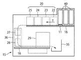
図1に示すように、カード発行システム15は、ケーシング36と、ケーシング36内に設けられ、多数のカードを収納するとともに未印画のカード11を順次供給するカード供給機構40と、カード供給機構40の下流側に設けられ、カード11の表面に画像情報や文字情報などを印画する印画装置20と、を備えている。また印画装置20の下流側には、カード11の表面を保護する保護シートをカードの表面に設ける保護シート形成部29が設けられている。また保護シート形成部29の下流側には、画像情報や文字情報などが印画され、保護シートが設けられたカード11を蓄積するスタッカ35が設けられている。
As shown in FIG. 1, the card issuing
なお本実施の形態において、所有者の画像情報や文字情報などが電子的に格納されたICチップ(図示せず)がカード11に実装されていてもよい。この場合、図1に示すリーダライタ27により、カード11のICチップに画像情報および文字情報が書き込まれてもよい。また本実施の形態において、カード11の表面だけでなく裏面にも、所有者の画像情報や文字情報などが印画されてもよい。この場合、図1に示す裏面印画ユニット28により、カード11の裏面に画像情報や文字情報などが印画されてもよい。
In the present embodiment, an IC chip (not shown) in which image information, character information, etc. of the owner is stored electronically may be mounted on the
(印画装置)
図1に示すように、印画装置20は、カード11を搬送方向Tに搬送する搬送機構16に沿って並べられ、カード11に対して所定の色で各々印画する複数の印画ユニットを含んでいる。例えば印画装置20は、カード11の搬送方向Tの上流側から順に、イエロー印画ユニット22、マゼンダ印画ユニット23、シアン印画ユニット24およびブラック印画ユニット25を含んでいる。なお本実施の形態において、「印画する」とは、カード上に顔写真などの画像情報を印画することだけでなく、カード上に文字情報などの文字情報を印字することも含んでいる。
(Printing device)
As illustrated in FIG. 1, the
(カード供給機構)
次に図2および図3を参照して、印画装置20に向けてカード11を供給するカード供給機構40について説明する。図2に示すように、カード供給機構40は、所定の供給方向Dに沿って供給路41上にカード11を供給し、これによって搬送機構16上にカード11を載置するよう構成されている。なお搬送機構16に沿って複数のカード供給機構40および供給路41が設けられていてもよい。
(Card supply mechanism)
Next, the
搬送機構16におけるカード11の搬送方向Tと、供給路41におけるカード11の供給方向Dとは、互いに平行であってもよく、若しくは、互いに非平行であってもよい。例えば図2に示すように、カード11が長辺13および短辺14を含む矩形状の形状を有する場合、搬送方向Tが、カード11の長辺13と平行になっており、一方、供給方向Dが、カード11の短辺14と平行になっていてもよい。すなわち、搬送方向Tと供給方向Dとが直交していてもよい。
The transport direction T of the
図3に示すように、カード供給機構40は、積み重ねられた複数のカード11を一枚ずつ下側から供給するよう構成されている。例えばカード供給機構40は、最も下側に位置するカード11に当接することができる爪部42aを含むカードピック42を有している。カードピック42は、爪部42aを供給方向Dに沿って駆動するよう構成されており、これによって、複数のカード11の束から最も下側に位置するカード11のみを供給路41に沿って供給することができる。
As shown in FIG. 3, the
図3に示すように、積み重ねられた複数のカード11の上には錘50が載置されており、このため、カード11の反りを抑制する、若しくは解消させることができる。このことにより、最後の一枚のカード11までカードピック42を用いてカード供給機構40から供給することができる。なお、積み重ねられた複数のカード11の上には、1個の錘50のみが載置されていてもよく、若しくは複数の錘50、例えば2個の錘50が載置されていてもよい。また図3において点線で示すように、積み重ねられた複数のカード11および錘50をとり囲むよう後述の容器45が配置されていてもよい。
As shown in FIG. 3, the
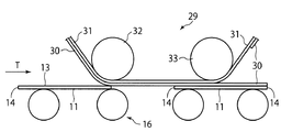
(保護シート形成部)
次に図4を参照して、カード11上に保護シート30を設ける保護シート形成部29について説明する。図4に示すように、保護シート形成部29は、基材31によって支持された保護シート30をカード11に対して押圧し、これによって保護シート30をカード11上に転写させる押圧ローラー32を有している。また保護シート形成部29は、保護シート30のうちカード11上に転写されていない部分を、保護シート30のうちカード11に対して押圧され転写された部分から剥離させる剥離ローラー33をさらに有していてもよい。
(Protective sheet forming part)
Next, with reference to FIG. 4, the protective
なお、搬送方向Tがカード11の長辺13と平行になっている場合、保護シート30は、カード11の長辺13に平行に延びており、また、カード11の短辺14に沿って保護シート30の剥離が実施される。
When the transport direction T is parallel to the
錘
次に図5および図6(a)(b)(c)を参照して、カード供給機構40の錘50について詳細に説明する。図5は、錘50を示す斜視図である。図5に示すように、錘50は、複数のカード11の上に載置される際にカード11と向かい合う下面51と、下面51と対向する上面52と、下面51と上面52との間に位置する少なくとも4つの側面と、を有している。4つの側面は、カード11の長辺13に平行に延びる一対の第1側面53と、カード11の短辺14に平行に延びる一対の第2側面54と、からなっている。なお「上面」、「下面」および「側面」という表現は、カード供給機構40において積み重ねられた複数のカード11の上に錘50が載置されている場合を基準としたものであり、その他の使用状況における錘50の向きを限定するものではない。
Weight Next, the
錘50の形状について詳細に説明する。図6(a)は、図5の錘50を第1側面53側から見た場合を示す側面図であり、図6(b)は、図5の錘を下面51側から見た場合を示す底面図であり、図6(c)は、図5の錘を第2側面54側から見た場合を示す側面図である。図6(a)(c)に示すように、第1側面53および第2側面54は、下面51側から上面52側に向かうにつれて内方に傾斜するよう構成されている。例えば、錘50の幅w1は、下面51側から上面52側に向かうにつれて小さくなっている。このため、錘50を側方から見た場合の形状は、台形状の形状となっている。また、下面51は上面52よりも大きくなっている。
The shape of the
また下面51には、下方に突出し、第1側面53に沿って延びる突出片55が設けられている。突出片55は、錘50が複数のカード11の上に載置される際にカード11に接する先端面55aと、下面51と先端面55aとの間に位置する外方側面55bおよび内方側面55cと、を有している。このうち外方側面55bは、図5および図6(c)に示すように、第1側面53と連続したものであってもよい。すなわち、第1側面53の一部が突出片55の外方側面55bとして利用されていてもよい。なお内方側面55cとは、外方側面55bよりも内方において先端面55aに沿って延びる側面のことである。
The
好ましくは、突出片55の内方側面55cは、下方に向かうにつれて、すなわち下面51から離れるにつれて外方に向かうよう傾斜している。この結果、突出片55は、図6(c)に示すように、下方に向かうにつれて先細になっている。これによって、後述するように、未印画のカード11がカード供給機構40から供給される際の振動などに起因して、カード供給機構40に残っているカード11や錘50の位置が水平方向に変化する場合であっても、錘50の突出片55が最も上側にあるカード11から滑り落ちて下方へ変位してしまうことを抑制することができる。同様に、カードが製造される場所からカードが発行される場所などへ未印画のカードを輸送する際の振動に関しても、錘50と、錘50の突出片55に接触しているカード11とが噛み込んで、容器45からカード11が取り出せなくなってしまうことを抑制することができる。
Preferably, the
錘50の略中央部には、指や所定の器具を引っ掛けることによって錘50を容器45から取り出したり搬送したりするための孔61が形成されていてもよい。また錘50の対向する一対の角部には、容器45のガイド部(図示せず)と嵌合可能な切欠き62が形成されていてもよい。また錘50の下面51には、カードピック42の爪部42aが通ることができる溝部64が形成されていてもよい。またカード供給機構40が、カード11の有無を検知するカード検知手段(図示せず)を有する場合、錘50の下面51には、カード検出手段がカード11の有無を検知する際に利用される凹部63が形成されていてもよい。これら孔61、切欠き62、凹部63および溝部64の具体的な構造や作用効果は、上述の特許文献1に記載されているので、ここでは詳細な説明を省略する。
A
次に、このような構成からなる本実施の形態の作用について説明する。 Next, the operation of the present embodiment having such a configuration will be described.
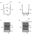
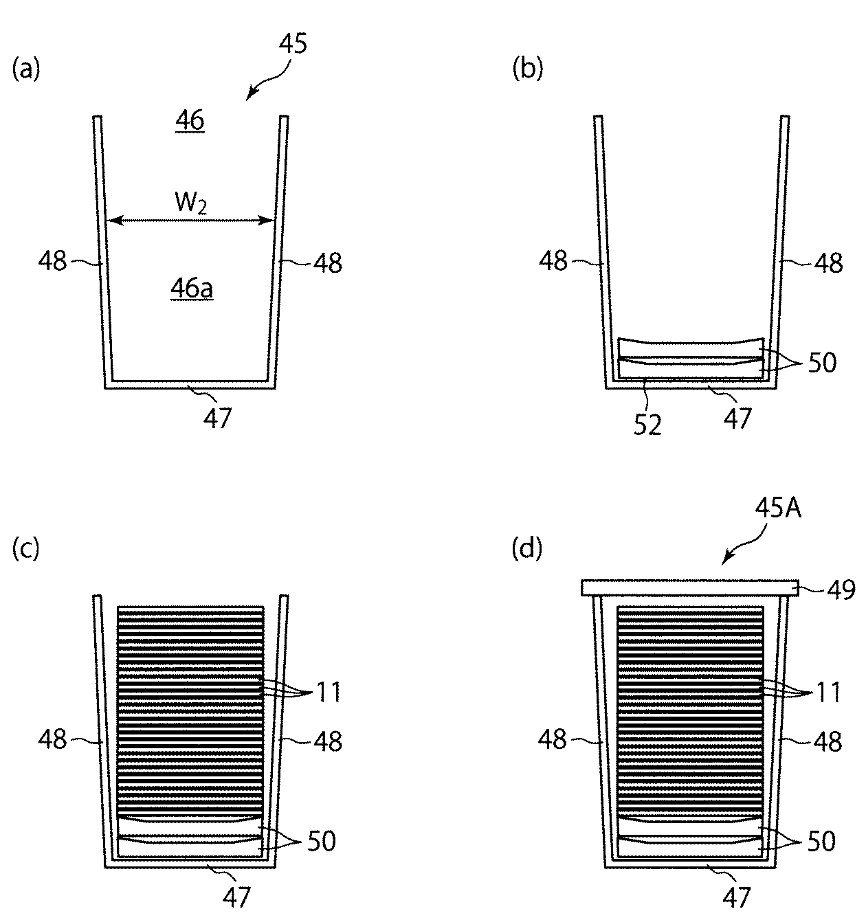
カード入り容器の構成方法
はじめに、容器45に複数のカード11を収容してカード入り容器45Aを構成する方法について、図7(a)(b)(c)(d)を参照して説明する。まず図7(a)に示すように、複数のカード11を収容するための収容空間46aが画定された容器45を準備する。容器45は、基部47と、基部47の反対側に開口部46を画定するよう設けられた側部48と、を有している。ここで側部48は、開口部46から基部47に向かうにつれて容器45が先細になるよう構成されている。例えば、収容空間46aの幅w2は、開口部46側から基部47側に向かうにつれて小さくなっている。
In configuring the beginning of the card container filled, how to configure the card container filled 45A houses a plurality of
容器45は一般に、金型を用いて樹脂を成形することによって作製される。この場合、容器45用の金型は、金型の開口部が容器45の開口部46に対応するよう構成される。ここで上述のように、容器45は、開口部46から基部47に向かうにつれて先細になるよう構成されている。このため、容器45用の金型の内部の空間は、金型の開口部から金型の内部に向かうにつれて先細になっている。このように金型の内部にテーパを設けることによって、容器45を金型から取り出す作業を容易化することができる。
The
次に、図7(b)に示すように、錘50の上面52が容器45の基部47と向かい合うよう、容器45の収容空間46a内に錘50を配置する。なお錘50も、容器45と同様に、金型を用いて樹脂を成形することによって作製され得る。この場合、錘50用の金型は、金型の開口部が錘50の下面51に対応するよう構成される。ここで上述のように、錘50は、下面51が上面52よりも大きくなるよう構成されている。このため、錘50用の金型の内部の空間は、金型の開口部から金型の内部に向かうにつれて先細になっている。これによって、金型を用いて容器45を作製する場合と同様に、錘50を金型から取り出す作業を容易化することができる。また容器45および錘50はいずれも、図7(b)の下方に向かうにつれて先細になるよう構成されており、このため、容器45の中に錘50を配置する作業を迅速に実施することができる。
Next, as shown in FIG. 7B, the
その後、図7(c)に示すように、錘50の上に複数のカード11を積み重ねる。次に、図7(d)に示すように、容器45の開口部46を閉鎖部材49によって閉鎖する。このようにして、複数のカード11が収容されたカード入り容器45Aを得ることができる。
Thereafter, as shown in FIG. 7C, a plurality of
なお、カード入り容器45Aを構成する方法が、上述の方法に限定されることはない。例えば、予め複数のカード11を積載し、次に、上方に向かって先細りになるよう、すなわち下面51がカード11に接するよう、積載されたカード11の上に錘50を積載し、その後、カード11および錘50に容器45を被せ、次に、容器45を上下反転させ、そして容器45の開口部46を閉鎖部材49によって閉鎖することによって、カード入り容器45Aを構成してもよい。この場合も、錘50および容器45がいずれも同一の方向に向かって先細になっているため、カード11および錘50を迅速に容器45内に収納することができる。すなわち、カード11および錘50に迅速に容器45を被せることができる。
Note that the method of configuring the carded
カード入り容器45Aは、例えば、未印画のカード11の製造場所から、カード発行システム15を用いて未印画のカード11に印画処理を施してカード11を発行する場所などへ輸送される。
For example, the card-containing
ところで図7(d)に示すように、カード入り容器45Aの中には、複数のカード11が錘50の上に積み重ねられている。このため、最も下側に位置するカード11と錘50との間には、大きな圧力が発生している。また、輸送中にカード入り容器45Aが振動すると、最も下側に位置するカード11と錘50との間に大きな摩擦力が発生することも考えられる。さらに、近年はカード11にICチップが搭載されており、このため、最も下側に位置するカード11と錘50との間に発生する圧力や摩擦力が、従来よりも大きくなっている。
By the way, as shown in FIG.7 (d), the some card |
ここで本実施の形態によれば、錘50の下面51には、第1側面53に沿って延びる突出片55が設けられている。このため、突出片55が下面51に設けられていない場合に比べて、錘50とカード11との間の接触面積を低減することができる。これによって、錘50とカード11とが接触する接触位置を限定することができる。このことにより、プレ印刷部分、印画部分及び保護シート転写部分等への損傷を抑制することができる。
Here, according to the present embodiment, the
カードの供給方法
カード11発行場所へ輸送されたカード入り容器45Aのカード11は、カード発行システム15のカード供給機構40に移し替えられる。この際、カード11とともに錘50がカード供給機構40に移し替えられ、図8(a)に示すように、錘50が複数のカード11の上に載置される。なお、カード入り容器45Aを、開口部46が下方を向くようカード発行システム15に装着することにより、カード11および錘50がカード供給機構40に移し替えられてもよい。カード供給機構40に移し替えられたカード11は、図3に示すカードピック42によって一枚ずつ供給される。
Card Supply Method The
カード供給機構40において、錘50は、積層された複数のカード11を下方に押圧し、これによって、カード11の反りを抑制する、若しくは解消させるよう、作用する。ここで本実施の形態によれば、錘50の下面51には、第1側面53に沿って延びる突出片55が設けられている。このため、錘50がカード11に及ぼす圧力を、カード11の長辺13近傍において長辺13に沿って局所的に発生させることができる。これによって、突出片55が下面51に設けられていない場合や、突出片55が下面51の外周の全域に沿って設けられている場合に比べて、カード11の反りを効率的に抑制する、若しくは解消させることができる。
In the
また本実施の形態によれば、突出片55が、第1側面53に沿って延びるよう構成されている。また第1側面53および第2側面54は、前記下面側から前記上面側に向かうにつれて内方に傾斜するよう構成されており、この結果、下面51が上面52よりも大きくなっている。このため、下面51が上面52よりも小さくなっている場合に比べて、容器45の内壁と錘50との間の隙間を小さくしながら、突出片55をカード11の長辺13のより近傍に当接させることができる。これによって、カード11の表面のうち、カード11の中央部を含む領域であって、錘50が接触していない領域(図8(a)において符号Rで表されている領域であり、以下、非接触領域Rとも称される)を大きく確保することができる。一般に、画像情報や文字情報は、カード11の外周近傍ではなくカード11の中央部近傍に印画される。従って、非接触領域Rを大きく確保することにより、画像情報や文字情報が印画される領域に傷が形成される可能性を低くすることができる。
Further, according to the present embodiment, the protruding
次に、カード供給機構40においてカード11や錘50の位置が水平方向に変化した場合における、本実施の形態による錘50によってもたらされる利点について説明する。図8(b)は、最も上側に位置するカード11が、図8(a)の場合の位置よりも右方向に変位した場合を示す図である。仮に、錘50の突出片が、下面51に対して垂直に下方に突出する凸部として構成されている場合、最も上側に位置するカード11が変位すると、当該カード11から突出片が滑り落ち、当該カード11の下にあるカード11に突出片が当接することが考えられる。すなわち、カード11に対する錘50のいわゆる噛み込みが発生することが考えられる。この場合、最も上側に位置するカード11に対して錘50が圧力を印加することが困難になり、この結果、最後の一枚のカード11をカードピック42によって供給することが困難になることが考えられる。これに対して、本実施の形態においては、図8(b)に示すように、突出片55は、下方に向かうにつれて先細になっている。このため、カード11が右方向に変位した場合であっても、突出片55の内方側面55cがカード11の端部に引っかかることができる。従って、錘50は、最も上側に位置するカード11に対して圧力を印加し続けることができ、このことにより、最後の一枚のカード11までカードピック42によって排出することが可能となる。
Next, the advantages provided by the
次に、保護シート形成部29によってカード11上に保護シート30を設ける場合における、本実施の形態による錘50によってもたらされる利点について説明する。上述のように、保護シート形成部29においては、カード11の搬送方向Tが、カード11の長辺13に平行になっている。また保護シート形成部29においては、カード11上に保護シート30を転写する際、カード11の短辺14に沿って保護シート30の転写が実施される。この際、短辺14の近傍においてカード11の表面に傷が形成されていると、保護シート30の転写が阻害され、この結果、カード11の短辺14の近傍に保護シートの未転写部分が生じることがある。ここで本実施の形態において、錘50の突出片55は、カード11の長辺13に平行に延びる第1側面53に沿うよう構成されている。この場合、仮に、カード11と錘50との間の圧力や摩擦に起因してカード11の表面に傷が形成されるとしても、そのような傷は、カード11の長辺13に沿って形成されている。すなわち、カード11の短辺14の近傍には傷が形成されておらず、このため、保護シート30の転写が阻害されることを防ぐことができる。このことにより、保護シート30の端部に未転写部分が形成されることを抑制することができる。
Next, advantages provided by the
なお、上述した実施の形態に対して様々な変更を加えることが可能である。以下、図面を参照しながら、変形の一例について説明する。以下の説明および以下の説明で用いる図面では、上述した実施の形態と同様に構成されている部分について、上述の実施の形態で用いた符号と同一の符号を用いることとし、重複する説明を省略する。 Note that various modifications can be made to the above-described embodiment. Hereinafter, an example of modification will be described with reference to the drawings. In the following description and the drawings used in the following description, the same reference numerals as those used in the above-described embodiment are used for portions that are configured in the same manner as in the above-described embodiment, and redundant description is omitted. To do.
錘の第1の変形例
図9および図10(a)(b)(c)に示すように、錘50の上面52には、上方に突出する凸部56が設けられていてもよい。ここで、凸部56の高さh2は、突出片55の高さh1よりも大きくなっている。以下、本変形例による錘50によってもたらされる利点について説明する。
First Modification of Weight As shown in FIGS. 9 and 10A, 10B, and 10C, the
錘50を保管または輸送する際、保管または輸送に必要な空間を小さくするため、図11に示すように、複数の錘50が積み重ねられることがある。このような積み重ねは、容器45の中に錘50が収容されている際や、カード供給機構40においてカード11の上に錘50が載置されている際にも生じることがある。ここで本変形例によれば、上述のように、凸部56の高さh2が、突出片55の高さh1よりも大きくなっている。このため、複数の錘50が積み重ねられているとき、錘50の凸部56は、当該錘50の上に載置された錘50の下面51の領域であって、突出片55が設けられていない領域に当接することができる。この結果、図11に示すように、錘50の突出片55が、当該錘50の下に位置する錘50に接触することが防がれている。従って、錘50を保管または輸送している間に錘50の突出片55が他の錘50に接触して傷つくことを抑制することができる。仮に、錘50の突出片55に裂け目や凸凹などの微細な傷が形成されている場合、突出片55の傷に起因して、突出片55に当接するカード11の表面に傷が形成されてしまうことが考えられる。これに対して本変形例によれば、錘50の突出片55が傷つくことを抑制することができ、このことにより、カード11の表面に傷が形成されてしまうことを抑制することができる。
When the
錘の第2の変形例
また図12および図13(a)(b)(c)に示すように、錘50の下面51には、下方に突出し、第2側面54に沿って延びる追加突出片57が設けられていてもよい。この追加突出片57は、第1側面53に沿って延びる突出片55に接するよう構成されている。例えば図12および図13(b)に示されているように、突出片55と追加突出片57との組合せによって錘50の下面51の角部にL字状の突出片が形成されるよう、突出片55および追加突出片57が構成されている。これによって、カード供給機構40においてカード11や錘50の位置が水平方向に変化した場合であっても、カード11に対する錘50の噛み込みが発生することをより確実に防ぐことができる。
As shown in a second modification of the weight also FIGS. 12 and 13 (a) (b) ( c), the
好ましくは、第2側面54に沿って延びる追加突出片57の長さは、第1側面53に沿って延びる突出片55の長さよりも短くなっている。これによって、カード11の短辺14近傍におけるカード11と錘50との間の接触面積を小さくすることができ、このことにより、カード11の短辺14に沿って傷が形成されてしまうことを抑制することができる。
Preferably, the length of the additional protruding
その他の変形例
なお上述の本実施の形態および各変形例において、突出片55が、第1側面53に沿って延びるよう構成される例を示したが、これに限られることはない。錘50の突出片55は、カード発行装置15の保護シート形成部29におけるカード11の搬送方向Tに平行なカード11の辺に対応するよう、錘50の第1側面53または第2側面54のいずれか一方に沿って延びていればよい。例えば、保護シート形成部29におけるカード11の搬送方向Tが、カード11の短辺14に平行になっている場合、錘50の突出片55は、カード11の短辺14に平行に延びる第2側面54に沿うよう構成されていてもよい。この場合、仮に、カード11と錘50との間の圧力や摩擦に起因してカード11の表面に傷が形成されるとしても、そのような傷は、カード11の短辺14に沿って形成される。すなわち、カード11の長辺13の近傍には傷が形成されておらず、このため、保護シート30の転写が阻害されることを防ぐことができる。このことにより、保護シート30の端部に未転写部分が形成されることを抑制することができる。
なお突出片55が第2側面54に沿うよう構成されている場合、上述の追加突出片57が、第1側面53に沿うよう構成されていてもよい。
Other Modifications In the above-described embodiment and modifications, the example in which the protruding
When the protruding
なお、上述した実施の形態に対するいくつかの変形例を説明してきたが、当然に、複数の変形例を適宜組み合わせて適用することも可能である。 In addition, although some modified examples with respect to the above-described embodiment have been described, naturally, a plurality of modified examples can be applied in combination as appropriate.
以下、実施例を用いて本発明をより詳細に説明するが、本発明はこの実施例に限定されるものではない。 EXAMPLES Hereinafter, although this invention is demonstrated in detail using an Example, this invention is not limited to this Example.
(実施例1)
錘を用いることによってカード11の反りが矯正される程度について実験した。錘としては、第1側面53に沿って延びる突出片55が設けられた2個の錘50を使用した。また、2個の錘50による荷重は、0.0714kgfであった。カード11としては、短辺14の方向に沿って1.5mmの反りが生じているカード11を使用した。
Example 1
An experiment was conducted on the degree to which the warp of the
反りが矯正される程度を計測した結果、反りが1.5mmから0.8mmに矯正されるという結果を得た。 As a result of measuring the degree of correction of the warp, the result that the warp was corrected from 1.5 mm to 0.8 mm was obtained.
(比較例1A)
突出片55が設けられていない錘を用いたこと以外は、実施例1の場合と同様にして、カード11の反りが矯正される程度を実験した。具体的には、2個の錘による0.0714kgfの荷重がカード11に印加されているという条件の下、反りが矯正される程度を計測した。結果、反りが1.5mmから0.9mmに矯正されるという結果を得た。
(Comparative Example 1A)
An experiment was conducted to the extent that the warpage of the
(比較例1B)
錘の数を2個から1個に変更したこと以外は、比較例1Aの場合と同様にして、カード11の反りが矯正される程度を実験した。具体的には、1個の錘からの0.0357kgfの荷重がカード11に印加されているという条件の下、反りが矯正される程度を計測した。結果、反りが1.5mmから1.15mmに矯正されるという結果を得た。
(Comparative Example 1B)
Except that the number of weights was changed from two to one, an experiment was conducted to the extent that the warpage of the
実施例1および比較例1A、1Bから分かるように、錘50からの荷重をカード11の長辺13に集中させることにより、カード11の反りを効果的に矯正することができた。
As can be seen from Example 1 and Comparative Examples 1A and 1B, the warpage of the
(実施例2および比較例2)
300枚のカード11が収容された容器45が、開口部46が下方を向くようカード発行システム15に装着されている場合を想定して、カード11の表面の領域のうちどの範囲の領域に錘の突出片が接触し得るかについて、シミュレーションにより検証した。シミュレーションツールとしては、@RISKを用いた。錘としては、上方に向かうにつれてテーパ角θ1で先細になるとともに、下面に設けられた突出部55を有する錘50(図14(a)に示す、実施例2による錘)、および、下方に向かうにつれてテーパ角θ2で先細になるとともに、下面に設けられた突出部65を有する錘60(図14(b)に示す、比較例2による錘)の二種類を用いた。
(Example 2 and Comparative Example 2)
Assuming that the
カード11としては、長辺の寸法が85.595mmであり、短辺の寸法が53.975mmであり、厚みが0.790mmである矩形状のカード11を用いた。容器45としては、上方に向かってテーパ角θ3で先細になる容器45を用いた。テーパ角θ3は、カード11と容器45の内壁との間の遊びが大きくなりすぎてカード11の位置決めが困難になることを防ぐことと、JIS規格で定められているカード11の寸法とを考慮して、0.2度に設定した。一方、錘50のテーパ角θ1および錘60のテーパ角θ2は、容器45のテーパ角θ3に比べて自由に設定され得るものであり、ここでは3度に設定した。
As the
積み重ねられた300枚のカード11のうちの最も上側のカード11と、錘との間の接触可能範囲を、容器45および錘の寸法を変化させながら検証した。接触可能範囲としては、図14(a)(b)に示すように、カード11と錘とが水平方向において互いに反対方向に変位した場合の、容器45の内壁から錘の突出片までの距離X1と、錘の突出片の幅X2との和を用いた。距離X1と幅X2との和が小さくなるよう容器45および錘の寸法を最適化した結果、図14(a)に示す錘50の方が、図14(b)に示す錘60に比べて、距離X1と幅X2との和を小さくすることができることを確認した。
The contactable range between the
なお、上述の検証の結果として得られた、図14(a)に示す錘50および容器45の最適な寸法および好ましい寸法範囲(下限値および上限値)は、以下の表1に示す通りであった。
11 カード
15 カード発行システム
40 カード供給機構
45 容器
45A カード入り容器
50 錘
51 下面
52 上面
55 突出片
11
Claims (8)
前記カードは、長辺および短辺を含む矩形状の形状を有し、
前記錘は、
前記カードと向かい合う下面と、前記下面と対向する上面と、前記上面と前記下面との間に位置する少なくとも4つの側面と、を有し、
前記4つの側面は、前記カードの前記長辺に平行に延びる一対の第1側面と、前記カードの前記短辺に平行に延びる一対の第2側面と、からなり、
前記第1側面および前記第2側面は、前記下面側から前記上面側に向かうにつれて内方に傾斜するよう構成されており、
前記下面に、下方に突出し、前記第1側面のみに沿って延びる突出片が設けられている、錘。 A weight placed on a plurality of stacked cards,
The card has a rectangular shape including a long side and a short side,
The weight is
A lower surface facing the card, an upper surface facing the lower surface, and at least four side surfaces located between the upper surface and the lower surface,
The four side surfaces include a pair of first side surfaces extending in parallel to the long side of the card and a pair of second side surfaces extending in parallel to the short side of the card,
The first side surface and the second side surface are configured to inwardly incline from the lower surface side toward the upper surface side,
A weight that protrudes downward and extends only along the first side surface is provided on the lower surface.
前記外方側面は、前記第1側面と連続しており、
前記内方側面は、前記外方側面よりも内方に位置している、請求項1に記載の錘。 The protruding piece has a front end surface in contact with the card, an outer side surface and an inner side surface located between the lower surface and the front end surface,
It said outer side surface is contiguous with the first side surface,
The weight according to claim 1, wherein the inner side surface is located inward of the outer side surface.
前記凸部の高さは、前記突出片の高さよりも大きくなっている、請求項1乃至3のいずれか一項に記載の錘。 The upper surface is provided with a convex portion protruding upward,
The weight according to any one of claims 1 to 3 , wherein a height of the convex portion is larger than a height of the protruding piece.
複数のカードを収容する容器と、
前記容器の中に積み重ねられた複数のカードと、
前記容器の中に配置された錘と、を備え、
前記容器は、基部と、前記基部の反対側に開口部を画定するよう設けられた側部と、を有し、
前記容器の前記側部は、前記開口部から前記基部に向かうにつれて前記容器が先細になるよう構成されており、
前記カードは、長辺および短辺を含む矩形状の形状を有し、
前記錘は、請求項1乃至5のいずれか一項に記載の錘であって、前記錘の前記上面が前記容器の前記基部と向かい合うよう前記容器内に配置された錘からなる、カード入り容器。 A container containing a plurality of cards,
A container containing a plurality of cards;
A plurality of cards stacked in the container;
A weight disposed in the container,
The container has a base and a side provided to define an opening on the opposite side of the base;
The side portion of the container is configured such that the container tapers from the opening toward the base,
The card has a rectangular shape including a long side and a short side,
The weight is a weight according to any one of claims 1 to 5 , wherein the card-filled container comprises a weight arranged in the container so that the upper surface of the weight faces the base of the container. .
前記カードは、長辺および短辺を含む矩形状の形状を有し、
積み重ねられた複数のカードの上には錘が載置されており、
前記錘は、請求項1乃至4のいずれか一項に記載の錘からなる、カード供給機構。 A card supply mechanism for supplying a plurality of stacked cards one by one,
The card has a rectangular shape including a long side and a short side,
A weight is placed on the stacked cards,
The card supply mechanism comprising the weight according to any one of claims 1 to 4 .
前記カード供給機構は、前記カード上に保護シートを設ける保護シート形成部を備えたカード発行装置に設けられており、
前記カードは、長辺および短辺を含む矩形状の形状を有し、
積み重ねられた複数のカードの上には錘が載置されており、
前記錘は、
前記カードと向かい合う下面と、前記下面と対向する上面と、前記上面と前記下面との間に位置する少なくとも4つの側面と、を有し、
前記4つの側面は、前記カードの前記長辺に平行に延びる一対の第1側面と、前記カードの前記短辺に平行に延びる一対の第2側面と、からなり、
前記第1側面および前記第2側面は、前記下面側から前記上面側に向かうにつれて内方に傾斜するよう構成されており、
前記下面に、下方に突出する突出片が設けられており、
前記錘の前記突出片は、前記カード発行装置の前記保護シート形成部における前記カードの搬送方向に平行な前記カードの辺に対応するよう、前記錘の前記第1側面または前記第2側面のいずれか一方のみに沿って延びている、カード供給機構。 A card supply mechanism for supplying a plurality of stacked cards one by one,
The card supply mechanism is provided in a card issuing device provided with a protective sheet forming unit for providing a protective sheet on the card,
The card has a rectangular shape including a long side and a short side,
A weight is placed on the stacked cards,
The weight is
A lower surface facing the card, an upper surface facing the lower surface, and at least four side surfaces located between the upper surface and the lower surface,
The four side surfaces include a pair of first side surfaces extending in parallel to the long side of the card and a pair of second side surfaces extending in parallel to the short side of the card,
The first side surface and the second side surface are configured to inwardly incline from the lower surface side toward the upper surface side,
A projecting piece projecting downward is provided on the lower surface,
Either the first side surface or the second side surface of the weight so that the protruding piece of the weight corresponds to the side of the card parallel to the card transport direction in the protective sheet forming portion of the card issuing device. one only along the extending, card feed mechanism or.
Priority Applications (1)
| Application Number | Priority Date | Filing Date | Title |
|---|---|---|---|
| JP2012217688A JP6025035B2 (en) | 2012-09-28 | 2012-09-28 | Weight placed on card, container with card provided with weight, and card supply mechanism provided with weight |
Applications Claiming Priority (1)
| Application Number | Priority Date | Filing Date | Title |
|---|---|---|---|
| JP2012217688A JP6025035B2 (en) | 2012-09-28 | 2012-09-28 | Weight placed on card, container with card provided with weight, and card supply mechanism provided with weight |
Publications (2)
| Publication Number | Publication Date |
|---|---|
| JP2014071699A JP2014071699A (en) | 2014-04-21 |
| JP6025035B2 true JP6025035B2 (en) | 2016-11-16 |
Family
ID=50746834
Family Applications (1)
| Application Number | Title | Priority Date | Filing Date |
|---|---|---|---|
| JP2012217688A Active JP6025035B2 (en) | 2012-09-28 | 2012-09-28 | Weight placed on card, container with card provided with weight, and card supply mechanism provided with weight |
Country Status (1)
| Country | Link |
|---|---|
| JP (1) | JP6025035B2 (en) |
Families Citing this family (2)
| Publication number | Priority date | Publication date | Assignee | Title |
|---|---|---|---|---|
| JP2019064792A (en) * | 2017-09-29 | 2019-04-25 | 大日本印刷株式会社 | Card supply device |
| JP7243243B2 (en) * | 2019-02-07 | 2023-03-22 | 大日本印刷株式会社 | Card storage device, card supply device and card printer |
Family Cites Families (3)
| Publication number | Priority date | Publication date | Assignee | Title |
|---|---|---|---|---|
| JPH05286578A (en) * | 1992-04-10 | 1993-11-02 | Berujii:Kk | Card issuing device |
| JPH07277532A (en) * | 1994-04-01 | 1995-10-24 | Konica Corp | Weight and weight storage container |
| JPH10338365A (en) * | 1997-06-11 | 1998-12-22 | Toshiba Corp | Card ejection device |
-
2012
- 2012-09-28 JP JP2012217688A patent/JP6025035B2/en active Active
Also Published As
| Publication number | Publication date |
|---|---|
| JP2014071699A (en) | 2014-04-21 |
Similar Documents
| Publication | Publication Date | Title |
|---|---|---|
| JP6025035B2 (en) | Weight placed on card, container with card provided with weight, and card supply mechanism provided with weight | |
| JP5759272B2 (en) | Medium cassette and image forming apparatus | |
| CN100509592C (en) | Paper feed tray and printer furnished with the tray | |
| JP2009007081A (en) | Recording medium storage device and image forming apparatus | |
| WO2012074001A1 (en) | Information recording device | |
| JP6818248B2 (en) | Card supply system | |
| JP5939462B2 (en) | Card loading / transfer device and card printer | |
| JP4315031B2 (en) | Paper cassette | |
| JP5304482B2 (en) | Paper package | |
| JP4213607B2 (en) | Printing device | |
| JP6716925B2 (en) | Thermal transfer image receiving sheet | |
| JP2013077232A (en) | Card loading and transporting device and card printer | |
| JP7205141B2 (en) | Card storage unit, card feeder and card packaging container | |
| JP2007099407A (en) | Card carry-out device and card printer | |
| JP4783672B2 (en) | Alignment unit and image forming apparatus having the same | |
| JP5955182B2 (en) | Paper cassette and printing device | |
| JP4569415B2 (en) | Small printing device and manual feeding member | |
| JP3969357B2 (en) | Printing device | |
| JP4811229B2 (en) | Paper supply device and paper bundle printer | |
| EP1681599B1 (en) | Image forming apparatus and sheet feeding device | |
| JP2007076891A (en) | Card conveying device and card printer | |
| JP4332481B2 (en) | Paper feeder | |
| JP4860266B2 (en) | ID card making device | |
| JP4930174B2 (en) | Media cassette | |
| JP2007076890A (en) | Card conveying device and card printer |
Legal Events
| Date | Code | Title | Description |
|---|---|---|---|
| A621 | Written request for application examination |
Free format text: JAPANESE INTERMEDIATE CODE: A621 Effective date: 20150730 |
|
| A977 | Report on retrieval |
Free format text: JAPANESE INTERMEDIATE CODE: A971007 Effective date: 20160420 |
|
| A131 | Notification of reasons for refusal |
Free format text: JAPANESE INTERMEDIATE CODE: A131 Effective date: 20160524 |
|
| A521 | Written amendment |
Free format text: JAPANESE INTERMEDIATE CODE: A523 Effective date: 20160725 |
|
| TRDD | Decision of grant or rejection written | ||
| A01 | Written decision to grant a patent or to grant a registration (utility model) |
Free format text: JAPANESE INTERMEDIATE CODE: A01 Effective date: 20160916 |
|
| A61 | First payment of annual fees (during grant procedure) |
Free format text: JAPANESE INTERMEDIATE CODE: A61 Effective date: 20160929 |
|
| R150 | Certificate of patent or registration of utility model |
Ref document number: 6025035 Country of ref document: JP Free format text: JAPANESE INTERMEDIATE CODE: R150 |
|
| RD02 | Notification of acceptance of power of attorney |
Free format text: JAPANESE INTERMEDIATE CODE: R3D02 |