JP6024792B2 - Electronic clock and electronic equipment - Google Patents
Electronic clock and electronic equipment Download PDFInfo
- Publication number
- JP6024792B2 JP6024792B2 JP2015130551A JP2015130551A JP6024792B2 JP 6024792 B2 JP6024792 B2 JP 6024792B2 JP 2015130551 A JP2015130551 A JP 2015130551A JP 2015130551 A JP2015130551 A JP 2015130551A JP 6024792 B2 JP6024792 B2 JP 6024792B2
- Authority
- JP
- Japan
- Prior art keywords
- state
- display
- crown
- hand
- setting
- Prior art date
- Legal status (The legal status is an assumption and is not a legal conclusion. Google has not performed a legal analysis and makes no representation as to the accuracy of the status listed.)
- Active
Links
Images


Landscapes
- Electromechanical Clocks (AREA)
- Electric Clocks (AREA)
Description
この発明は、りゅうずを用いて機能設定を行う電子時計及び電子機器に関する。 The present invention relates to an electronic timepiece and an electronic device that perform function setting using a crown.
従来より、指針と操作部材である「りゅうず」とを備えた時計が知られている。このよ
うな時計において、りゅうずは時計本体の側面に設けられ、りゅうずが押し込まれて戻さ
れている状態(りゅうず戻し状態)では時計の指針は時刻を表示し、使用者がりゅうずを
引くと(りゅうず引き状態)、時計の秒針は停止し、りゅうずを回転させることで時分針
を修正することが可能である。
近年、りゅうずに時分針修正以外の種々の機能を持たせた時計、すなわち、りゅうずの
操作により、これらの機能の表示あるいはこれら機能に関する設定が可能である時計が開
発されている。たとえば、時計の時分針および秒針は、「りゅうず戻し状態」において時
刻を表示しているが、「りゅうず引き状態」で時計の秒針が「標準電波受信が設定されて
いるか、設定されていないか」を表示するような時計である。そして、「りゅうず引き状
態」にて使用者は、りゅうずを回転させることにより、標準電波受信機能を設定または解
除することができる。
2. Description of the Related Art Conventionally, a timepiece having a pointer and an operation member “Crown” is known. In such a watch, the crown is provided on the side of the watch body. When the crown is pushed in and returned (in the crown-returned state), the watch hands display the time, and the user pushes the crown. When pulled (the crown is pulled), the second hand of the watch stops and the hour and minute hands can be corrected by rotating the crown.
In recent years, a timepiece having various functions other than the hour / minute hand correction, that is, a timepiece capable of displaying these functions or setting related to these functions by operating the crown has been developed. For example, the hour / minute and second hands of the watch display the time when the crown is in the “retracted state”, but the second hand of the watch is “standard radio wave reception set or not set” It is a clock that displays "?". The user can set or cancel the standard radio wave reception function by rotating the crown in the “crown pulling state”.
このような、りゅうずの多機能化に対応して、以下のような技術が開示されている。特
許文献1では、2段引きのりゅうず(2段引き状態/1段引き状態/零段引き状態(りゅ
うず戻し状態))において、りゅうずを2段引き状態から1段引き状態にする際に、誤っ
て零段引き状態に入ってしまうことを防止するため、2段引き状態から1段引き状態を通
過したのち、一定期間りゅうず入力を無効にする技術が開示されている。
特許文献2では、モード切替の為りゅうずを1段引き状態にした際に、秒針を30秒位
置で停止させる等の手段により警告表示して、りゅうずの押し込み忘れによるモード誤切
替発生の可能性を低減させる技術が開示されている。
The following techniques are disclosed in response to the increase in the number of functions of the crown. In Patent Document 1, when the crown is changed from the two-step pulling state to the one-step pulling state in the two-step pulling crown (two-step pulling state / one-step pulling state / zero-step pulling state (crown return state)). In order to prevent accidental entry into the zero-pull state, a technique is disclosed in which the crown input is invalidated for a certain period after passing from the two-pull state to the one-pull state.
In Patent Document 2, when the crown is pulled to the first stage for mode switching, a warning is displayed by means such as stopping the second hand at the 30-second position, and mode erroneous switching due to forgetting to push the crown is possible. A technique for reducing the performance is disclosed.
ところで、「りゅうず戻し状態」(零段引き状態)と「りゅうず引き状態」(1段引き
状態)における秒針の指し示す機能表示内容を異ならせる場合、以下のような不具合が存
在していた。
By the way, when the function display contents indicated by the second hand are different in the “returning state” (zero pulling state) and the “crown pulling state” (one step pulling state), the following problems exist.
例えば、りゅうずが引き状態になると、標準電波の受信設定モードに移行するような場
合を仮定する。具体的には、りゅうず引き状態において、秒針の機能は秒の指針から標準
電波受信設定のON/OFFを指針するように変化し、りゅうずを回転することで標準電
波受信設定のON/OFFを切替える場合を仮定する。このような場合、りゅうずを戻す
ときに誤ってりゅうずが回転してしまうと、秒針の設定切替表示がされることなく、通常
表示状態である秒の表示に切り替わってしまい、誤って設定されてしまった設定情報が表
示されないという課題が存在していた。
For example, it is assumed that when the crown is pulled, the mode changes to the standard radio wave reception setting mode. Specifically, when the crown is pulled, the function of the second hand changes from the second hand to turn on / off the standard radio wave reception setting, and turning the crown turns the standard radio wave reception setting on / off. Is assumed to be switched. In such a case, if the crown rotates accidentally when the crown is returned, the setting display of the second hand is not displayed and the second display is switched to the normal display state. There was a problem that the setting information that was not displayed.
とくに、「ねじロックりゅうず」の場合にかかる課題が顕著であった。ねじロックりゅ
うずとは、防水性を高めるために用いられる「りゅうず」である。りゅうずの一部にネジ
が切ってあり、操作しない場合には、時計本体の所定部分にネジ締めしておくものである
。使用者は先ず、ネジを例えば手前に回転して緩め、引くことのできる状態(まだ零段引
きの状態)にしてから、りゅうずを引いて、標準電波受信モードに移行させる。標準電波
受信モードでの操作を終えると使用者はりゅうずを戻し、その後、ネジを締める。しかし
、りゅうずを戻すとともに、ネジロック操作をしてしまう、すなわち回転動作と戻す動作
を同時に行ってしまう事があり、秒針が時刻の秒表示に戻ってしまうために、誤って設定
されてしまった設定情報が認識されないという課題が存在していた。
In particular, the problem in the case of the “screw lock crown” is remarkable. The screw lock crown is a “crown” used to improve waterproofness. The crown is partly screwed and when not operated, it is screwed onto a predetermined part of the watch body. First, the user first turns the screw, for example, to loosen it, makes it ready for pulling (still in the zero-pull state), pulls the crown, and shifts to the standard radio wave reception mode. When the operation in the standard radio wave reception mode is completed, the user returns the crown, and then tightens the screw. However, when the crown is returned, the screw lock operation is performed, that is, the rotating operation and the returning operation may be performed at the same time, and the second hand returns to the second display of the time. There was a problem that the setting information was not recognized.
本発明の目的は、第2の表示状態から第1の表示状態への移行操作において、第2の表示状態での設定内容を確認できる電子機器を提供することにある。 The objective of this invention is providing the electronic device which can confirm the setting content in a 2nd display state in operation to transfer from a 2nd display state to a 1st display state .
本発明は、上記目的を達成するため、
軸方向への引き・戻し操作と引き状態での回転操作が可能な回転スイッチと、前記回転スイッチの回転操作によって機能の有効、無効の設定変更を行う設定変更手段と、前記設定変更手段による設定変更後の状態表示を表示する第2の表示状態から時刻表示する第1の表示状態への移行は、前記第2の表示状態の表示を所定期間保持した後に行わせる表示状態保持手段と、を備えることを特徴とする電子時計である。
In order to achieve the above object, the present invention
A rotary switch capable of pulling / returning operation in the axial direction and rotating operation in the pulled state, setting changing means for changing the setting of validity / invalidity of the function by rotating the rotary switch, and setting by the setting changing means Display state holding means for causing the display of the second display state to be performed after holding the display of the second display state for a predetermined period of time from the second display state that displays the changed state display to the first display state that displays the time. It is an electronic timepiece characterized by comprising.
本発明に従うと、誤ってスイッチを操作させてしまっても、誤った操作に起因する第2の表示状態における設定内容を確認できる電子機器を提供することができる。 According to the present invention, it is possible to provide an electronic device that can confirm the setting contents in the second display state caused by an erroneous operation even if the switch is operated by mistake.
以下、本発明の実施形態を図面に基づいて説明する。 Hereinafter, embodiments of the present invention will be described with reference to the drawings.
図1は、本発明の実施形態に係る電子時計100の外観を示す図である。電子時計10
0は、時計ケース1と文字板7と秒針31、分針32、時針33および回転スイッチであ
るりゅうず10を備えている。文字板7上で3本の指針(秒針31、分針32、時針33
)が回転して、時刻表示を行う。ここで、文字板7と秒針31、分針32、時針33が表
示部である。
FIG. 1 is a diagram showing an external appearance of an
0 includes a watch case 1, a
) Rotates to display the time. Here, the
図2は、本発明の実施形態に係る電子時計100の内部構成を示すブロック図である。
この電子時計100は、複数の指針(秒針31、分針32、時針33)と、秒針31を運
針する第1モータ34と、分針32および時針33を運針する第2モータ35と、第1モ
ータ34の回転運動を秒針に伝達するとともに、第2モータ35の回転運動を分針32お
よび時針33に伝達する輪列機構36と、第1モータ34をステップ駆動する駆動回路3
7と、第2モータ35をステップ駆動する駆動回路38と、りゅうず10を操作すること
により、りゅうず軸方向の位置情報とりゅうず回転情報を出力する検出部52と、標準電
波を受信するアンテナANと、標準電波からタイムコードを検波する電波受信部41と、
計時のために一定周期の信号を生成する発振回路44および分周回路45と、計時を行う
計時回路46と、電子時計全体の制御を行うCPU(中央演算処理装置)40と、CPU
40に作業用のメモリ空間を提供するRAM43(Random Access Memory)と、CPU4
0が実行する制御プログラムや制御データが格納されたROM42(Read Only Memory)
と、アラーム音を出力するためのブザー回路47およびスピーカ48等を備えている。
FIG. 2 is a block diagram showing an internal configuration of the
The
7, a
An
A RAM 43 (Random Access Memory) that provides a working memory space to the
ROM 42 (Read Only Memory) storing control program executed by 0 and control data
A
検出部52は、りゅうずの回転を検出する磁気センサ15および磁気センサ15の検出
信号を処理してりゅうずの回転方向および回転角度を算出する回転検出部50と、りゅう
ずを戻し・引いた際の段位置を検出するスイッチ部51(接触バネ部22a、接点部25
a、25b)を備えている。
The
a, 25b).
ROM42には、駆動回路37、38にパルス信号を出力して指針31〜33を回転さ
せ、時刻を表示する時刻表示モード処理のプログラム、標準電波による時刻修正とそれに
付随した処理とを行う「標準電波による修正処理」のプログラム、ならびに、「りゅうず
引き/戻し処理」、「りゅうず回転処理」のプログラムなどが格納されている。
The
図3は電子時計100の部分断面図であって、りゅうず部6およびその近傍を示した図
である。図4は、図3におけるりゅうず部6を回路基板25側から見た拡大裏面図である
。図5は、図4において回路基板を取り外した状態を示した要部の拡大裏面図である。図
6は、図4のA−A矢視における拡大断面図である。図7は、図5の状態で巻真を第2の
位置に引き出した状態を示した要部の拡大裏面図である。図8は、図7のB−B矢視にお
ける拡大断面図である。図9は図5において地板にオシドリ、オシドリばね、スイッチ板
を配置した状態を示した要部の拡大裏面図である。図10は図9のスイッチ板およびこれ
に対応する箇所の回路基板を示し、(a)は図9のE−E矢視における要部の拡大断面図
、(b)はその回路基板の接点部を示した図である。図11は、磁石部材の拡大断面図を
示した図である。
FIG. 3 is a partial cross-sectional view of the
電子時計100の時計ケース1の上部開口部には、時計ガラス2がパッキン2aを介し
て取り付けられており、この時計ケースの下部には、裏蓋3が防水リング3aを介して取
り付けられている。時計ケース1の内部には、図3に示すように時計モジュール4が中枠
5によって設けられている。また、文字板7の上面にはリング状の見切部材8が設けられ
ている。
A watch glass 2 is attached to the upper opening of the watch case 1 of the
りゅうず部6は、図3に示すように、時計ケース1側壁部に回転可能に挿入されて外部
に突出するりゅうず10と、このりゅうず10に取り付けられて時計モジュール4内の地
板11に軸方向に移動操作可能で且つその軸を中心とする回転方向にも回転操作可能に設
けられた巻真12と、この巻真12の軸方向における移動位置を規制する位置規制部材1
3と、巻真12にスライド可能に設けられて巻真12と共に回転する磁石部材14と、こ
の磁石部材14の円周方向に位置して磁石部材14の回転を検出する磁気センサ15等で
構成されている。
As shown in FIG. 3, the
3, a
巻真12は図3に示すように、ほぼ丸棒状に形成され、その一端部にりゅうず10が取
り付けられ、時計ケース1の側壁部に設けられた貫通孔1aに外部から挿入されている。
また、巻真12は、その他端部が地板11に軸方向に移動操作可能で、且つその軸を中心
とする回転方向にも回転操作可能に取り付けられている。これにより、巻真12は、りゅ
うず10を引き出し方向に操作すると、これに伴って軸方向に移動し、また竜頭10を回
転方向に操作すると、軸回りに回転するように構成されている。
As shown in FIG. 3, the winding
Further, the winding
また、この巻真12は、図5〜図8に示すように、そのほぼ中間部に小径の段差凹部1
2aが環状に設けられており、この段差凹部12aにおける時計モジュール4の内部側に
位置する先端側(図6では左端側)には、図6および図8に示すように、後述する磁石部
材14をスライド可能に取り付けるための、断面形状が四角形状の角棒状に形成された係
合軸部16が設けられている。
Further, as shown in FIGS. 5 to 8, the winding
As shown in FIGS. 6 and 8, a
さらに、この巻真12の内部側に位置する係合軸部16の先端部(図6では左端部)には
、図6および図8に示すように、小径の軸部12bが設けられている。この軸部12bは
、丸棒状に形成され、地板11に設けられたガイド穴11a内に軸方向に移動可能で且つ
その軸を中心に回転可能な状態で挿入されている。これにより、巻真12は、図6に示す
ように、軸方向(矢印X方向)に押し込まれて戻された第1の位置(零段の位置)と、図
8に示すように、軸方向(矢印Y方向)に引き出された第2の位置(1段の位置)とに移
動するように構成されている。
Furthermore, as shown in FIGS. 6 and 8, a small-
位置規制部材13は、図5〜図9に示すように、オシドリ20、オシドリばね21、ス
イッチ板22、および押え板23を備えている。オシドリ20は、図5に示すように、平
板状に形成され、地板11に設けられた支持軸17に回動可能に取り付けられ、巻真12
の軸方向への移動に応じて支持軸17を中心に回動するように構成されている。
As shown in FIGS. 5 to 9, the
It is comprised so that it may rotate centering on the
すなわち、オシドリ20には、図9に示すように、巻真12の段差凹部12a内に配置
される連動アーム部20aと、オシドリばね21によって弾力的に位置規制される連動ピ
ン20bと、スイッチ板22をオシドリ20と共に回動させる連結ピン20cとが設けら
れている。これにより、オシドリ20は、巻真12が軸方向に移動すると、巻真12の段
差凹部12aの移動に伴って連動アーム部20aが揺動することにより、支持軸17を中
心に回動するように構成されている。
That is, as shown in FIG. 9, the
オシドリばね21は、図9に示すように、板ばねであり、オシドリ20の近傍に位置す
る箇所の地板11に固定され、オシドリ20の連動ピン20bを弾力的に保持して位置規
制することにより、オシドリ20の回動位置を規制して巻真12の軸方向の移動位置を規
制するように構成されている。すなわち、このオシドリばね21は、図9に示すように、
その先端部にオシドリ20の連動ピン20bを弾力的に保持する位置規制部24が設けら
れている。
As shown in FIG. 9, the
A
この位置規制部24には、図9に示すように、連動ピン20bを弾力的に係止する複数
の係止凹部24a、24bが設けられている。これにより、オシドリばね21は、図6に
示すように、巻真12が押し込まれて戻された第1の位置状態のときに、図5、図9に示
すように、オシドリ20の連動ピン20bを位置規制部24の一方の係止凹部24aで弾
力的に係止することにより、巻真12を第1の位置(零段の位置)に規制するように構成
されている。
As shown in FIG. 9, the
また、このオシドリばね21は、図8に示すように、巻真12が軸方向に引き出された
第2の位置(1段の位置)に移動するときに、図7に示すように、オシドリ20が支持軸
17を中心に回動し、これに伴って連動ピン20bが回転移動して位置規制部24を弾性
変形させ、この弾性変形した位置規制部24の他方の係止凹部24bがオシドリ20の連
動ピン20bを弾力的に係止することにより、巻真12を第2の位置(1段の位置)に規
制するように構成されている。
In addition, as shown in FIG. 8, when the winding
スイッチ板22は、図9、図10に示すように、金属板からなり、オシドリ20と共に
地板11の支持軸17に回転可能に取り付けられている。このスイッチ板22には、図1
0(a)に示すように、後述する回路基板25の上面に接触して摺動する接触ばね部22a
が延設されている。延設されている方向は、図9に示すように、オシドリ20の連動アー
ム部20aと反対側に向けられている。このスイッチ板22の所定箇所には、図9に示す
ように、オシドリ20の連結ピン20cが挿入する挿入孔22bが設けられている。
As shown in FIGS. 9 and 10, the
As shown in 0 (a), a
Is extended. As shown in FIG. 9, the extending direction is directed to the opposite side to the
これにより、スイッチ板22は、図10(a)に示すように、接触ばね部22aの先端
部が回路基板25の上面に接触した状態で、支持軸17を中心にオシドリ20と共に回転
移動し、この接触ばね部22aの先端部が回路基板25の上面に設けられた接点部25a
、25bに対する接触位置を切り替えるように構成されている。押え板23は、図5、図
7に示すように、オシドリばね21と共に地板11にねじ23aによって取り付けられて
、オシドリばね21およびスイッチ板22を押え付けることにより、オシドリ20を地板
11に押し付けるように構成されている。
Thereby, as shown in FIG. 10A, the
, 25b is configured to switch the contact position. As shown in FIGS. 5 and 7, the
ここで、巻真12の軸方向の位置と、スイッチ板22の接触ばね部22aの状態との関
係を説明する。
Here, the relationship between the axial position of the winding
巻真12が押し込まれて戻された状態(第1の位置:零段位置)では、既述のように、
オシドリ20の連動ピン20bは位置規制部24の一方の係止凹部24aで弾力的に係止
され、図5、図9のように、スイッチ板22が支持軸17を中心にオシドリ20と共に時
計回りに回動した状態になり、図10(b)にて接触ばね部22aが接点部25aに移動
して接触する。
In the state in which the winding
The interlocking
一方、巻真12が軸方向に引き出された状態(第2の位置:1段位置)では、オシドリ
20の連動ピン20bは位置規制部24の他方の係止凹部24bで弾力的に係止され、図
7にてスイッチ板22が支持軸17を中心にオシドリ20と共に反時計回りに回動した状
態になり、図10(b)にて接触ばね部22aが接点部25bに移動して接触する。
On the other hand, in a state where the winding
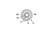
図11は、磁石部材14をその中心軸に直交する面で切断した状態を示している。巻真
12にスライド可能に設けられた磁石部材14は、図6、図8、図11に示すように、リ
ング状の磁石18と、この磁石18を包む樹脂部19とからなり、全体がほぼ円形板状に
形成され、その中心部に巻真12の係合軸部15が挿入する断面四角形状の係合孔18a
が設けられ、図6、図8に示すように、外周面の一部が地板11に設けられた磁石押え部
26によって押え付けられた構成になっている。
FIG. 11 shows a state in which the
As shown in FIGS. 6 and 8, a part of the outer peripheral surface is pressed by a
これにより、磁石部材14は、図6、図8に示すように、その係合孔18aに巻真12
の係合軸部16がスライド可能に挿入し、この状態で巻真12が軸方向に移動しても、磁
石押え部26によって押えられていることにより、巻真12に対し相対的に移動して常に
一定の位置に保持され、この状態で巻真12と共に回転するように構成されている。
Thereby, as shown in FIGS. 6 and 8, the
Even if the
一方、磁気センサ15は、図3、図6および図8に示すように、地板11の裏面(図6
では下面)に設けられた回路基板25の下面における磁石部材14と対応する箇所に設け
られている。これにより、磁気センサ15は、回路基板25を間に挟んで磁石部材14と
対応している。この磁気センサ15は、2つの磁気検出素子、例えば2つの磁気抵抗素子
15a、15b(MR素子:Magneto Resistance 素子)と、出力をデジタル化するIC
とを1パッケージに収めたもので、2つの磁気抵抗素子15a、15bで磁石部材14の
回転に伴う磁界の変化を検出して、高い(ハイ:H)、低い(ロウ:L)の2種類の検出
信号を出力するように構成されている。
On the other hand, as shown in FIG. 3, FIG. 6, and FIG.
The lower surface of the
Are detected in one package, and the two
すなわち、この磁気センサ15は、2つの磁気抵抗素子15a、15bの設置位置が異
なっていることにより、磁石部材14の回転に伴う磁界の変化を検出する際、出力に位相
差が生じ、この位相差によって2種類の検出信号を出力することにより、磁石部材14の
回転を検出するように構成されている。この場合、2種類の検出信号は、回転検出部50
で解析されて、磁石部材14の回転角度および回転方向を算出する。また、磁気センサ1
5の周囲には、図3、図6および図8に示すように、耐磁板27が配置されている。
That is, the
The rotation angle and the rotation direction of the
As shown in FIGS. 3, 6, and 8, a magnetic-
次に、上記のように構成された電子時計100のりゅうず引き/戻し処理に関する動作
について、図12から図16を参照して説明する。
Next, operations relating to the crown / return process of the
図12は、りゅうず10を操作して時刻表示機能から、他機能状態表示である、標準電
波受信機能(以下、標準電波受信モードという)に移行させ、受信設定のON/OFFを
切り替える動作についての従来の例を示す説明図である。
FIG. 12 shows an operation of switching the ON / OFF of the reception setting by operating the
ここで、標準電波の受信設定のON状態とは、標準電波受信機能が設定されて有効にな
っている状態である。この状態では、たとえば、1日に1度標準電波を受信して自己の時
刻を修正する。具体的には、CPU40はROM42に格納された「標準電波による修正
処理」のプログラムを実行して、所定時刻(例えば午後12時)になった場合に電波受信
部41を起動させて標準電波を受信してタイムコードを取り込む電波受信処理、取り込ん
だタイムコードを判別して計時回路47の計時データを修正する自動時刻修正処理を行う
。一方、標準電波の受信設定のOFF状態とは、標準電波受信機能が解除されて無効にな
っている状態である。
Here, the ON state of the standard radio wave reception setting is a state in which the standard radio wave reception function is set and enabled. In this state, for example, a standard radio wave is received once a day to correct its own time. Specifically, the
図12(A)はりゅうず10が戻し状態であり、指針は「第1の表示状態」(時刻表示
機能)を示している。すなわち、秒針31、分針32、時針33は、ともに時刻を示して
いる。図12(B)は、りゅうず10を引いた状態(りゅうず引き状態)を示す。この場
合、秒針5は、「第2の表示状態」である標準電波受信モードを表示する。図12(B)
では、秒針31が、文字板7の外周の「ON」文字を指針している。これは、標準電波受
信設定が有効(以下「ON」状態という)であることを示している。一方、分針32、時
針33は時刻表示を継続している。
In FIG. 12A, the
Then, the
図12(B)において、使用者が、りゅうず10を例えば時計回転方向に90度回転さ
せると、標準電波受信設定が有効(ON状態)から無効(以下「OFF」状態という)へ
設定変更され、秒針31が32ステップ/秒の速度でON位置からOFF位置に変位する
。図12(C)は秒針31がOFF位置に変位した後の状態を示す。
In FIG. 12B, when the user rotates the
図12(C)において、使用者が、りゅうず10を押し込む場合を説明する。りゅうず
10を押し込むと、図12(D)に示すように、「第1の表示状態」(時刻表示機能)に
戻る。すなわち、秒針が、指示されていた設定値(図12(C)ではOFF位置)から現
在の秒を示す位置に32ステップ/秒の速度で変位する。
A case where the user pushes in the
ところが、りゅうず10を押し込んで戻すときに誤って、りゅうず10が回転してしま
うと、標準電波受信設定がOFFからONに変わってしまう。特に、ねじロックりゅうず
の場合、一度に操作しようとして、回しながら押してしまうことがある。その場合におい
ても、図12(D)に示すように秒針は、「第2の表示状態」(標準電波受信モード)を
表示することなく「第1の表示状態」(時刻表示機能)に戻ってしまう。したがって、戻
し時にりゅうず10が回転しなかった図12(D)の状態と、りゅうず10が回転してO
Nに変化してしまった図12(E)の判別がつかない。
However, if the
The determination of FIG. 12E that has changed to N cannot be made.
図13は図12に対応した、りゅうずと指針の状況を示すタイミングチャートである。
図13の上段はりゅうずの軸方向の位置を示す。りゅうず引き状態を信号ハイ(H)、り
ゅうず戻し状態を信号ロウ(L)として示している。なお、スイッチ部51において、り
ゅうず引き状態では、接触ばね部22aが接点部25bと接触し、戻し状態では、接触ば
ね部22aが接点部25aと接触している。図13の中段は、りゅうず回転の有無を示し
ている。すなわち、回転検出部50の出力に基づき、りゅうず回転時にパルス信号が出力
される。図13下段は、指針の状況を示したものである。
FIG. 13 is a timing chart showing the situation of the crown and the hand corresponding to FIG.
The upper part of FIG. 13 shows the position of the crown in the axial direction. The crown pulling state is shown as signal high (H), and the crown return state is shown as signal low (L). In addition, in the
図13において、最初はりゅうず戻し状態であり、信号はLを示している。そして、指
針は時刻を示している(第1の表示状態)。使用者がりゅうず10を引くと、りゅうず引
き状態となり、信号はLからHに変化する。信号Hが検出されると、秒針31の表示モー
ドは標準電波受信モードに変更され、秒を示していた秒針31は32ステップ/秒の速度
で標準電波受信ON位置に変位される。そして、使用者がりゅうず10を90度時計方向
に回転させると、図1における回転検出部50の出力がHになり、秒針31はON位置か
らOFF位置に変位する。
In FIG. 13, the crown is initially in the retracted state, and the signal indicates L. The hands indicate the time (first display state). When the user pulls the
次に使用者は、りゅうず10を戻そうとする。戻そうとする際、誤って回しながら戻し
てしまうと、りゅうず回転信号が出力され、CPU40は、標準電波受信設定をOFFか
らONに設定変更する。ところが、りゅうず回転とほぼ同時にりゅうずが戻されているの
で、秒針31は時刻表示機能に移行してしまう。このように、りゅうず10を戻すときに
誤ってりゅうず10が回転してしまうと、使用者が「誤って設定した状態」が表示される
ことがない。
Next, the user tries to return the
図14は、本発明の実施形態に係る、りゅうず10を操作して標準電波の受信設定モー
ドに移行させ、受信設定のON/OFFを切り替える動作についての説明図である。図1
4(A)〜(C)は図12(A)〜(C)に対応している。すなわち、図14(A)はり
ゅうず10が戻し状態で第1の表示状態(時刻表示機能)、図14(B)は、秒針31が
標準電波受信「ON」状態を表示、図14(C)は、使用者が標準電波受信「ON」状態
から標準電波受信「OFF」状態へ設定を変更した後の表示、をそれぞれ示している。
FIG. 14 is an explanatory diagram illustrating an operation of switching the reception setting ON / OFF by operating the
4 (A) to (C) correspond to FIGS. 12 (A) to (C). 14A shows the first display state (time display function) when the
ここで、使用者が、りゅうず10を戻して、時刻表示機能に移行させる場合を説明する
。本実施形態では、「りゅうず引き状態」から「りゅうず戻し状態」に移行する際に約1
秒間、秒針31がりゅうず引き状態における表示状態を保持するように構成されている。
したがって、使用者が誤ってりゅうず10を回転してしまった場合、図14(D)に示す
ように、秒針31は標準電波受信OFF状態から標準電波受信ON状態に変位し、約1秒
経過すると、図14(E)に示すように時計表示モードに移行する。このように、りゅう
ず10を戻すときに誤ってりゅうず10が回転してしまっても、使用者は「誤って設定し
た状態」を表示で確認することができる。
Here, a case where the user returns the
The
Therefore, when the user accidentally rotates the
図15は本発明の実施形態に係る、図14に対応した、りゅうずと指針の状況を示すタ
イミングチャートである。図15の中で、(A)〜(C)は、図13の(A)〜(C)に
対応している。図15(C)の後、使用者がりゅうず10を戻そうとする際、誤って回し
ながら戻してしまうと、図15中段に示すように、りゅうず回転信号が出力され、CPU
40は、標準電波受信設定をOFFからONに設定変更する。
FIG. 15 is a timing chart showing the situation of the crown and the hand corresponding to FIG. 14 according to the embodiment of the present invention. In FIG. 15, (A) to (C) correspond to (A) to (C) in FIG. When the user tries to return the
40 changes the standard radio wave reception setting from OFF to ON.
本実施形態では、「りゅうず引き状態」から「りゅうず戻し状態」に移行する際に約1
秒間、秒針31がりゅうず引き状態における表示状態を保持するように構成されている。
したがって、りゅうず10を戻すときに、誤ってりゅうずが回転してしまっても、秒針3
1は標準電波受信モードの表示を約1秒間行い、使用者は設定した状態が変わってしまっ
たことが確認できる。そこで、使用者は、後で設定を訂正することができる。
In the present embodiment, approximately 1 is required when shifting from the “retracted state” to the “returned state”.
The
Therefore, even if the crown rotates accidentally when the
1 displays the standard radio wave reception mode for about 1 second, and the user can confirm that the set state has changed. Therefore, the user can correct the setting later.
図16は、本発明の実施形態に係る、りゅうず引き/戻し処理のフローチャートを示す
。電子時計100の「りゅうず引き/戻し処理」に係る動作について図16のフローチャ
ートを参照して説明する。
FIG. 16 shows a flowchart of the crown pulling / returning process according to the embodiment of the present invention. The operation of the
「りゅうず引き/戻し処理」が開始されると、先ずCPU40は、りゅうず10が引き
状態から戻し状態に移行したかを判別する(ステップS1)。具体的には、CPU40は
、スイッチ部51に由来する信号が、信号H(引き状態)から信号L(戻し状態)に変化
したかを判別する。移行したと判別されれば、ステップS1で「YES」へ分岐し、秒針
の表示を標準電波受信モード(第2の表示状態)のまま約1秒間保持する(ステップS2
)。そして、時刻を指針させ(第1の表示状態)(ステップS3)、「りゅうず引き/戻
し処理」を終了する。ここで、CPU40およびステップS1、S2が、表示状態保持手
段である。また、CPU40およびステップS3が、表示制御手段である。
When the “crown pull / return process” is started, the
). Then, the time is indicated (first display state) (step S3), and the "crown pulling / returning process" is ended. Here, the
一方、ステップS1で「NO」に分岐すると、CPU40は、りゅうず10が戻し状態
から引き状態に移行したかを判別する(ステップS4)。移行したと判別されれば、ステ
ップS4で「YES」へ分岐し、標準電波受信モードに移行し(ステップS5)、秒針は
標準電波受信設定のON/OFFを指針する(ステップS6)。その後、「りゅうず引き
/戻し処理」を終了する。ここで、CPU40およびステップS5、S6が、表示制御手
段である。
On the other hand, when branching to “NO” in step S1, the
なお、ステップS4にて、りゅうず引き/戻し状態に変化がなかった場合には、「NO
」に分岐し、CPU40はそのまま「りゅうず引き/戻し処理」を終了する。
If there is no change in the crown / return state at step S4, "NO"
The
図17は、本発明の実施形態に係る、りゅうず回転処理のフローチャートを示す。電子
時計100の「りゅうず回転処理」に係る動作について図17のフローチャートを参照し
て説明する。
FIG. 17 shows a flowchart of the crown rotation process according to the embodiment of the present invention. The operation of the
「りゅうず回転処理」が開始されると、先ずCPU40は、現在の表示が標準電波受信
モード(第2の表示状態)であるか否かを判別する(ステップS10)。現在の表示が標
準電波受信モード(第2の表示状態)であると判別されれば、ステップS10で「YES
」へ分岐し、りゅうず回転の有無を判別する(ステップS11)。りゅうず回転が有った
と判別されると、ステップS11で「YES」へ分岐し、CPU40は、標準電波受信設
定のON/OFF状態を設定変更するとともに、秒針31を対応する指針位置に変位させ
る(ステップS12)。
When the “crown rotation process” is started, the
To determine whether or not the crown has been rotated (step S11). If it is determined that the crown has been rotated, the process branches to “YES” in step S11, and the
ステップS10またはステップS11で「NO」へ分岐すると、りゅうず回転処理を終
了する。ここで、CPU40およびステップS10〜ステップS12が、設定変更制御手
段である。
If branching to "NO" in step S10 or step S11, the crown rotation process is terminated. Here, the
以上のように、電子時計100では、りゅうずによる第2の表示状態から第1の表示状
態への移行は、第2の表示状態の表示を所定期間保持した後に行われるので、誤ってりゅ
うずを回転させてしまっても、誤った回転に起因する第2の表示状態における設定内容を
確認できる電子時計を提供することができる。
As described above, in the
また、表示部は、時計の文字板と指針から構成されており、第2の表示状態を表示する
指針は秒針であるので、秒針で異なる機能を表示することができる。
Further, the display unit is composed of a timepiece dial and a pointer, and the pointer for displaying the second display state is the second hand, so that different functions can be displayed with the second hand.
なお、本発明は、上記実施の形態に限られるものではなく、様々な変更が可能である。
例えば、本実施形態では、表示部において、「第2の表示状態」を表示するのは秒針であ
ったが、それには限定されない。分針でもよいし、時針であってもよい。また、表示部は
、針式でなく、液晶表示や、有機EL表示等の表示素子から構成される表示部であっても
よい。この場合、表示部は、「りゅうず戻し状態」と、「りゅうず引き状態」に対応して
「第1の表示状態」と「第2の表示状態」を時間順次に表示部に表示する構成を有する。
The present invention is not limited to the above-described embodiment, and various modifications can be made.
For example, in the present embodiment, the display unit displays the “second display state” with the second hand, but is not limited thereto. A minute hand or an hour hand may be used. Further, the display unit is not a needle type, and may be a display unit configured by a display element such as a liquid crystal display or an organic EL display. In this case, the display unit displays the “first display state” and the “second display state” on the display unit sequentially in time corresponding to the “return state” and the “retractor state”. Have
この場合、表示部への表示を、液晶表示素子で行わせることもできるので、デジタル表
示においてもりゅうずを活用することができる。
In this case, since the display on the display unit can be performed by a liquid crystal display element, the crown can also be used in digital display.
また、本実施形態では、りゅうず10の段位置が、2つ、すなわち、りゅうず引き状態
(1段引き状態)、りゅうず戻し状態(零段状態)であるが、3段階以上の状態を有して
いても良い。この場合、本実施形態に対応するりゅうずの戻し状態とりゅうずの引き状態
とは隣接する段になっていれば良い。
In the present embodiment, the
この場合、りゅうずの軸方向への移動が3段階以上可能に構成され、りゅうずの戻し状
態とりゅうずの引き状態が隣接する段になっていればよいので、りゅうずの機能をさらに
追加することも可能となる。
In this case, the crown can be moved in three or more stages in the axial direction, and it is sufficient that the crown is pulled back and the pulling state of the crown is an adjacent stage. It is also possible to do.
また、本実施形態では、「第2の表示状態」の1例として標準電波受信設定について説
明したが、りゅうずによる「第2の表示状態」はそれに限定されず、例えば、アラームO
N/OFFの設定であってもよい。この場合、アラーム機能が他機能であり、有効とは、
アラーム設定がONになっていることをいい、無効とはアラーム設定がOFFになってい
る状態をいう。また、それ以外の機能であっても、選択的に切り替えることができる機能
であれば本発明の他機能として適用可能である。
In this embodiment, the standard radio wave reception setting has been described as an example of the “second display state”. However, the “second display state” by the crown is not limited thereto, and for example, an alarm O
N / OFF may be set. In this case, the alarm function is another function.
It means that the alarm setting is ON, and “invalid” means that the alarm setting is OFF. In addition, even other functions can be applied as other functions of the present invention as long as they can be selectively switched.
この場合、他機能として、標準電波受信機能または、アラーム報知機能であるので、そ
れらの機能を第2の表示状態として、誤った回転に起因する第2の表示状態における設定
内容を確認できる電子時計を提供することができる。
In this case, since the standard radio wave reception function or the alarm notification function is used as another function, the electronic timepiece can confirm the setting contents in the second display state caused by erroneous rotation with these functions as the second display state. Can be provided.
また、本実施形態では、りゅうず10の回転検出部50は、りゅうず回転は一方向だけ
(パルスの極性はプラスのみ)で、りゅうずが90度回転すると1パルス出力し、設定が
たとえばONになり、さらに90度回して180度回転したときにさらにパルスが発生し
、設定がたとえばOFFになるが、1パルス出力するための回転角は90度でなくてよく
、例えば45度でもよい。また、それ以外の構成として、例えば、時計回転方向に所定角
度回転すると、設定が例えばOFFからONに変化し、反時計方向に回転したとき例えば
、設定がONからOFFに変化するように構成することもできる。
In the present embodiment, the
また、本実施形態では、りゅうず部6として、りゅうず10の回転を磁気で検出する場
合を示したが、それには限定されない。たとえば、フォトインタラプタにより光学的にり
ゅうず10の回転を検出しても良い。さらには機構的な接点を利用してりゅうず10の回
転を検出しても良い。
In the present embodiment, the case where the rotation of the
本発明の実施形態を説明したが、本発明の範囲は上述の実施の形態に限定するものでは
なく、特許請求の範囲に記載された発明とその均等の範囲に含まれる。以下に、本願出願
の当初の特許請求の範囲に記載された発明を付記する。
[付記]
<請求項1>
軸方向への引き・戻し操作と引き状態での回転操作が可能な回転スイッチと、
前記回転スイッチの操作による移動位置情報と回転情報を検出する検出部と、
回転スイッチ戻し状態で、表示部に時刻表示する第1の表示状態とし、回転スイッチ引
き状態で、前記表示部に時刻表示以外の機能の状態を表示する第2の表示状態とする表示
制御手段と、
前記第2の表示状態において、前記回転スイッチの回転操作による前記検出部の回転情
報に基づき、前記機能の有効、無効の設定変更を行わせ、当該設定変更後の状態表示を行
わせる設定変更制御手段と、
前記第2の表示状態から前記第1の表示状態への移行は、第2の表示状態の表示を所定
期間保持した後に行わせる表示状態保持手段と、
を備えることを特徴とする電子時計。
<請求項2>
前記表示部は、時計の文字板と指針から構成されており、前記第2の表示状態を表示す
る指針は秒針であることを特徴とする請求項1記載の電子時計。
<請求項3>
前記表示部は、表示素子で構成されていることを特徴とする請求項1記載の電子時計。
<請求項4>
前記回転スイッチの軸方向への移動が3段階以上可能に構成され、前記回転スイッチの
戻し状態と回転スイッチの引き状態が隣接する段になっていることを特徴とする請求項2
または請求項3に記載の電子時計。
<請求項5>
前記機能は、標準電波受信機能または、アラーム報知機能であることを特徴とする請求
項2〜請求項4のいずれか一項に記載の電子時計。
Although the embodiment of the present invention has been described, the scope of the present invention is not limited to the above-described embodiment, and is included in the invention described in the claims and the equivalent scope thereof. Hereinafter, the invention described in the scope of claims of the present application will be appended.
[Appendix]
<Claim 1>
A rotation switch that can be pulled and returned in the axial direction and rotated in the pulled state;
A detection unit for detecting movement position information and rotation information by operating the rotation switch;
Display control means for setting the first display state to display the time on the display unit in the rotary switch return state and the second display state for displaying the state of functions other than the time display on the display unit in the rotary switch pulling state; ,
In the second display state, setting change control for causing the function to be enabled / disabled is changed based on the rotation information of the detection unit by the rotation operation of the rotary switch, and the state display after the setting change is performed. Means,
A transition from the second display state to the first display state is performed after the display of the second display state is held for a predetermined period;
An electronic timepiece characterized by comprising:
<Claim 2>
2. The electronic timepiece according to claim 1, wherein the display unit includes a timepiece dial and a hand, and the hand for displaying the second display state is a second hand.
<Claim 3>
The electronic timepiece according to claim 1, wherein the display unit includes a display element.
<Claim 4>
The rotation switch is configured to be movable in three or more stages in the axial direction, and the return state of the rotation switch and the pulling state of the rotation switch are adjacent stages.
The electronic timepiece according to
<Claim 5>
The electronic timepiece according to any one of claims 2 to 4, wherein the function is a standard radio wave reception function or an alarm notification function.
1 時計ケース
1a 貫通孔
2 時計ガラス
2a パッキン
3 裏蓋
3a 防水リング
4 時計モジュール
5 中枠
6 りゅうず部
7 文字板(表示部)
8 リング状の見切部材
10 りゅうず
11 地板
11a ガイド穴
12 巻真
12a 段差凹部
12b 軸部
13 位置規制部材
14 磁石部材
15 磁気センサ(検出部)
15a、15b 磁気抵抗素子
16 係合軸部
17 支持軸
18 磁石
18a 係合孔
19 樹脂部
20 オシドリ
20a 連動アーム部
20b 連動ピン
20c 連結ピン
21 オシドリばね
22 スイッチ板
22a 接触ばね部
23 押さえ板
23a ネジ
24 位置規制部(オシドリばね)
24a、24b 係止凹部(オシドリばね)
25 回路基板
25a、25b 接点部
26 磁石押え部
27、30 耐磁板
27a、30a 取付部
27b、30b 開口部
31 秒針(表示部)
32 分針(表示部)
33 時針(表示部)
34 第1モータ
35 第2モータ
36 輪列機構
37 駆動回路
38 駆動回路
40 CPU(表示制御手段、設定変更制御手段、表示状態保持手段)
41 電波受信部
42 ROM
44 発信回路
45 分周回路
46 計時回路
47 ブザー回路
48 スピーカ
50 回転検出部(検出部)
51 スイッチ部(検出部)
52 検出部
DESCRIPTION OF SYMBOLS 1 Watch case 1a Through-hole 2
8 Ring-shaped
15a,
24a, 24b Locking recess (Pickling spring)
25
32 minute hand (display)
33 Hour hand (display)
34
41
44
51 Switch part (detection part)
52 Detector
Claims (5)
前記回転スイッチの回転操作によって機能の有効、無効の設定変更を行う設定変更手段と、
前記設定変更手段による設定変更後の状態表示を表示する第2の表示状態から時刻表示する第1の表示状態への移行は、前記第2の表示状態の表示を所定期間保持した後に行わせる表示状態保持手段と、を備えることを特徴とする電子時計。 A rotation switch that can be pulled and returned in the axial direction and rotated in the pulled state;
Setting changing means for changing the setting of the function valid / invalid by rotating the rotary switch;
The transition from the second display state that displays the state display after the setting change by the setting changing means to the first display state that displays the time is a display that is performed after holding the display of the second display state for a predetermined period. electronic timepiece characterized by comprising the state holding means.
前記回転スイッチの回転操作によって機能の有効、無効の設定変更を行う設定変更手段と、
前記設定変更制御手段による設定変更後の状態表示を表示する表示状態から他の表示状態への移行は、前記設定変更後の状態表示の表示を所定期間保持した後に行わせる表示状態保持手段と、を備えることを特徴とする電子機器。 A rotation switch that can be pulled and returned in the axial direction and rotated in the pulled state;
Setting changing means for changing the setting of the function valid / invalid by rotating the rotary switch;
The display state holding means for causing the transition from the display state for displaying the state display after the setting change by the setting change control means to another display state after holding the display of the state display after the setting change for a predetermined period ; An electronic device comprising:
Priority Applications (1)
| Application Number | Priority Date | Filing Date | Title |
|---|---|---|---|
| JP2015130551A JP6024792B2 (en) | 2015-06-30 | 2015-06-30 | Electronic clock and electronic equipment |
Applications Claiming Priority (1)
| Application Number | Priority Date | Filing Date | Title |
|---|---|---|---|
| JP2015130551A JP6024792B2 (en) | 2015-06-30 | 2015-06-30 | Electronic clock and electronic equipment |
Related Parent Applications (1)
| Application Number | Title | Priority Date | Filing Date |
|---|---|---|---|
| JP2011194536A Division JP5772411B2 (en) | 2011-09-07 | 2011-09-07 | Electronic clock |
Publications (2)
| Publication Number | Publication Date |
|---|---|
| JP2015212702A JP2015212702A (en) | 2015-11-26 |
| JP6024792B2 true JP6024792B2 (en) | 2016-11-16 |
Family
ID=54697011
Family Applications (1)
| Application Number | Title | Priority Date | Filing Date |
|---|---|---|---|
| JP2015130551A Active JP6024792B2 (en) | 2015-06-30 | 2015-06-30 | Electronic clock and electronic equipment |
Country Status (1)
| Country | Link |
|---|---|
| JP (1) | JP6024792B2 (en) |
Families Citing this family (1)
| Publication number | Priority date | Publication date | Assignee | Title |
|---|---|---|---|---|
| EP3835887B1 (en) * | 2019-12-10 | 2022-07-13 | The Swatch Group Research and Development Ltd | Watch provided with a controller |
Family Cites Families (2)
| Publication number | Priority date | Publication date | Assignee | Title |
|---|---|---|---|---|
| JPS5749877B2 (en) * | 1974-05-15 | 1982-10-25 | ||
| JPS6030910B2 (en) * | 1978-01-23 | 1985-07-19 | セイコーエプソン株式会社 | analog alarm clock |
-
2015
- 2015-06-30 JP JP2015130551A patent/JP6024792B2/en active Active
Also Published As
| Publication number | Publication date |
|---|---|
| JP2015212702A (en) | 2015-11-26 |
Similar Documents
| Publication | Publication Date | Title |
|---|---|---|
| JP5772411B2 (en) | Electronic clock | |
| EP2261938B1 (en) | Rotation switch and electronic timepiece | |
| US8305171B2 (en) | Rotary switch and electronic timepiece | |
| US8783944B2 (en) | Switch device and wristwatch | |
| JP2011165468A (en) | Rotary switch | |
| JP5128766B2 (en) | Rudder angle sensor | |
| EP2431709B1 (en) | Method for correcting a geomagnetic sensor for a mobile device, as well as a mobile device and a program | |
| JP6024792B2 (en) | Electronic clock and electronic equipment | |
| JP2018072259A (en) | Analog display device, electronic timepiece, display operation control method, and program | |
| JP2009008504A (en) | Pointer type electronic clock, and method for controlling the driving of pointers | |
| JP2017173180A (en) | Azimuth display device, azimuth display method, and program | |
| JP2011141218A (en) | Elevation angle display device | |
| JP2009156787A (en) | Device for discriminating penetration state, and electronic timepiece | |
| JP2010112860A (en) | Electronic compass | |
| US20220253018A1 (en) | Electronic Watch And Control Method For Electronic Watch | |
| JP2010066046A (en) | Electronic timepiece, indicator driving method and program of timepiece | |
| US11194293B2 (en) | Electronic timepiece | |
| JP3771521B2 (en) | Radio correction clock with alarm function | |
| JP5194871B2 (en) | Member position detecting device and electronic timepiece | |
| JP3626923B2 (en) | Pointer origin detection device for analog radio timepiece for vehicle and method for detecting the origin of the pointer | |
| JP5163322B2 (en) | Penetration state discrimination device and electronic timepiece | |
| JP2016031273A (en) | Electronic clock | |
| JP5071512B2 (en) | Electronic clock | |
| JP2013125004A (en) | Analog electronic timepiece | |
| JP2010190714A (en) | Analog electronic clock |
Legal Events
| Date | Code | Title | Description |
|---|---|---|---|
| A977 | Report on retrieval |
Free format text: JAPANESE INTERMEDIATE CODE: A971007 Effective date: 20160513 |
|
| A131 | Notification of reasons for refusal |
Free format text: JAPANESE INTERMEDIATE CODE: A131 Effective date: 20160607 |
|
| A521 | Written amendment |
Free format text: JAPANESE INTERMEDIATE CODE: A523 Effective date: 20160720 |
|
| TRDD | Decision of grant or rejection written | ||
| A01 | Written decision to grant a patent or to grant a registration (utility model) |
Free format text: JAPANESE INTERMEDIATE CODE: A01 Effective date: 20160913 |
|
| A61 | First payment of annual fees (during grant procedure) |
Free format text: JAPANESE INTERMEDIATE CODE: A61 Effective date: 20160926 |
|
| R150 | Certificate of patent or registration of utility model |
Ref document number: 6024792 Country of ref document: JP Free format text: JAPANESE INTERMEDIATE CODE: R150 |