JP6018111B2 - grill - Google Patents
grill Download PDFInfo
- Publication number
- JP6018111B2 JP6018111B2 JP2014075258A JP2014075258A JP6018111B2 JP 6018111 B2 JP6018111 B2 JP 6018111B2 JP 2014075258 A JP2014075258 A JP 2014075258A JP 2014075258 A JP2014075258 A JP 2014075258A JP 6018111 B2 JP6018111 B2 JP 6018111B2
- Authority
- JP
- Japan
- Prior art keywords
- grill
- burner
- plate
- ignition electrode
- mounting bracket
- Prior art date
- Legal status (The legal status is an assumption and is not a legal conclusion. Google has not performed a legal analysis and makes no representation as to the accuracy of the status listed.)
- Active
Links
Images


Description
本発明は、グリル庫と、グリル庫の天井板上に配置するグリルバーナとを備えるグリルに関する。 The present invention relates to a grill provided with a grill cabinet and a grill burner disposed on a ceiling plate of the grill cabinet.
従来、この種のグリルにおいて、グリルバーナは、バーナ本体と、天井板に開設したバーナ用開口に臨ませてバーナ本体の下面に固定される多数の炎孔を有する燃焼板とを備えている。そして、燃焼板の下方に点火電極とこれに対向するターゲットとを配置し、点火電極とターゲットとの間での火花放電でグリルバーナに点火されるようにしている(例えば、特許文献1参照)。尚、点火電極とターゲットは天井板に固定した取付ブラケットに取付けられている。 Conventionally, in this type of grill, the grill burner includes a burner body and a combustion plate having a number of flame holes that are fixed to the lower surface of the burner body so as to face a burner opening formed in the ceiling plate. An ignition electrode and a target facing the ignition electrode are arranged below the combustion plate so that the grill burner is ignited by spark discharge between the ignition electrode and the target (see, for example, Patent Document 1). The ignition electrode and the target are attached to a mounting bracket fixed to the ceiling plate.
ところで、グリルバーナの燃焼板は、一般的にセラミックス製であるが、コストダウンのために、燃焼板を板金製としたグリルバーナも知られている。燃焼板を板金製とした場合、燃焼板の所定部位の下方に点火電極の先端部を位置させ、点火電極と燃焼板の所定部位との間での火花放電でグリルバーナにダイレクト点火させるように構成できる。 By the way, although the combustion plate of a grill burner is generally made of ceramics, a grill burner in which the combustion plate is made of sheet metal is also known for cost reduction. When the combustion plate is made of sheet metal, the tip of the ignition electrode is positioned below a predetermined portion of the combustion plate, and the grill burner is directly ignited by spark discharge between the ignition electrode and the predetermined portion of the combustion plate. it can.
但し、この場合には、点火性能を向上させるために、燃焼板と点火電極とのスパークギャップを形成する相対位置精度を確保することが必要になる。然し、点火電極を従来例の如く天井板に固定の取付ブラケットに取付けたのでは、天井板と点火電極との相対位置精度は確保できても、天井板に対しグリルバーナが多少とも位置ずれすることがあるため、燃焼板と点火電極との相対位置精度を確保できなくなる。その結果、火花放電が混合気の薄い所で行われ、点火しにくくなる場合がある。 However, in this case, in order to improve the ignition performance, it is necessary to ensure the relative position accuracy for forming the spark gap between the combustion plate and the ignition electrode. However, if the ignition electrode is attached to the mounting bracket fixed to the ceiling plate as in the prior art, the grill burner is slightly displaced relative to the ceiling plate even if the relative positional accuracy between the ceiling plate and the ignition electrode can be secured. Therefore, the relative positional accuracy between the combustion plate and the ignition electrode cannot be ensured. As a result, spark discharge is performed in a place where the air-fuel mixture is thin, and ignition may be difficult.
本発明は、以上の点に鑑み、グリルバーナの燃焼板と点火電極との相対位置精度を確保して、点火電極と燃焼板の所定部位との間での火花放電による点火性能を向上できるようにしたグリルを提供することをその課題としている。 In view of the above, the present invention ensures the relative positional accuracy between the combustion plate of the grill burner and the ignition electrode, and can improve the ignition performance by spark discharge between the ignition electrode and a predetermined portion of the combustion plate. The challenge is to provide a grill.
上記課題を解決するために、本発明は、グリル庫と、グリル庫の天井板上に配置するグリルバーナとを備えるグリルであって、グリルバーナは、下面が開放された偏平箱形のバーナ本体と、バーナ本体の下面を覆うようにバーナ本体に固定された多数の炎孔を有する板金製の燃焼板とを備え、天井板に開設したバーナ用開口に燃焼板を臨ませた状態でグリルバーナが天井板上に配置され、燃焼板の所定部位の下方に先端部が位置する点火電極が設けられ、点火電極と燃焼板の所定部位との間での火花放電でグリルバーナに点火させるものにおいて、バーナ本体に固定したグリル庫の外部に位置する取付ブラケットに点火電極が固定され、点火電極の先端部が、天井板のバーナ用開口の周縁部から下方に屈曲する段差部に形成した透孔を通してグリル庫内に挿入されて、燃焼板の所定部位の下方に位置することを特徴とする。 In order to solve the above-mentioned problems, the present invention is a grill comprising a grill cabinet and a grill burner disposed on the ceiling plate of the grill cabinet, the grill burner having a flat box-shaped burner body whose bottom surface is open, The grill burner is provided with a combustion plate made of sheet metal having a large number of flame holes fixed to the burner body so as to cover the lower surface of the burner body, with the combustion plate facing the opening for the burner opened in the ceiling plate. An ignition electrode that is arranged above and has a tip positioned below a predetermined portion of the combustion plate and ignites the grill burner by spark discharge between the ignition electrode and the predetermined portion of the combustion plate. The ignition electrode is fixed to a mounting bracket located outside the fixed grill cabinet, and the tip of the ignition electrode passes through a through hole formed in a stepped portion bent downward from the peripheral edge of the burner opening of the ceiling plate. It is inserted into the drill chamber, characterized in that located below the predetermined portion of the combustion plate.
本発明によれば、バーナ本体に固定の取付ブラケットに点火電極が固定されるため、天井板に対しグリルバーナが位置ずれしても、バーナ本体に固定の燃焼板と点火電極との相対位置精度は確保される。従って、燃焼板の所定部位の下方に所定の間隔で正確に点火電極の先端部が位置し、点火電極の先端部と燃焼板の所定部位との間で確実に火花放電が行われて、点火性能が向上する。 According to the present invention, since the ignition electrode is fixed to the mounting bracket fixed to the burner body, even if the grill burner is displaced from the ceiling plate, the relative positional accuracy between the combustion plate fixed to the burner body and the ignition electrode is Secured. Accordingly, the tip of the ignition electrode is accurately positioned at a predetermined interval below the predetermined portion of the combustion plate, and a spark discharge is reliably performed between the tip of the ignition electrode and the predetermined portion of the combustion plate, so that the ignition Performance is improved.
また、本発明において、取付ブラケットに上方からネジ止めする押え板により点火電極を上方から押え付けた状態で取付ブラケットに固定する場合は、取付ブラケットに、天井板の段差部の下端から外方に張り出すフランジ部に当接して、取付ブラケットが下方に撓むことを防止するストッパ部を設けることが望ましい。これによれば、押え板のネジ止め作業に際し取付ブラケットに下方への押圧力が作用しても、取付ブラケットは下方に撓むことがなく、この撓みによって燃焼板と点火電極との相対位置精度に狂いを生ずることを防止できる。 In addition, in the present invention, when the ignition electrode is fixed to the mounting bracket in a state where the ignition electrode is pressed from above by the press plate screwed to the mounting bracket from above, the mounting bracket is moved outward from the lower end of the step portion of the ceiling plate. It is desirable to provide a stopper portion that abuts the flange portion that protrudes and prevents the mounting bracket from bending downward. According to this, even when a downward pressing force is applied to the mounting bracket during the screwing operation of the presser plate, the mounting bracket does not bend downward, and this bending causes relative positional accuracy between the combustion plate and the ignition electrode. Can be prevented from going crazy.
図1を参照して、1は本発明の実施形態のグリルを示している。このグリル1は、グリル庫2と、グリル庫2の上面を覆う天井板21上に配置したグリルバーナ3と、グリル庫2の前面に設けられた開閉自在なグリル扉4とを備えている。グリル庫2内には、図示省略したグリル皿とグリル皿上の焼き網とが収納され、焼き網に載置した被調理物がグリルバーナ3の燃焼により焼成される。
Referring to FIG. 1, reference numeral 1 denotes a grill according to an embodiment of the present invention. The grill 1 includes a
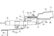
図2、図3も参照して、グリルバーナ3は、下面が開放された偏平箱形のバーナ本体31と、バーナ本体31の下面を覆うようにバーナ本体31に固定された多数の炎孔32aを有する板金製の燃焼板32と、バーナ本体31の横方向一側部に接続された混合管33とを備えている。バーナ本体31内には、混合管33を介して混合気(燃料ガスと一次空気との混合ガス)が供給され、この混合気が炎孔32aから噴出して燃焼する。
2 and 3, the
グリル庫2の天井板21には、バーナ用開口21aが開設されており、このバーナ用開口21aに燃焼板32を臨ませた状態でグリルバーナ3が天井板21上に配置される。具体的には、バーナ本体31の周縁のフランジ部31aの下面に燃焼板32の周縁部を重ね合わせた状態で、フランジ部31aの外縁をヘミング加工して、バーナ本体31に燃焼板32を固定し、天井板21のバーナ用開口21aの周縁部上面に、バーナ本体31のフランジ部31aを複数個所でネジ31b止めしている。
A burner opening 21 a is formed in the
また、グリル1には、燃焼板32の横方向他側の所定部位の下方に先端部5aが位置する点火電極5と、点火電極5に隣接する火炎検知素子たる熱電対6とが設けられている。そして、点火電極5と燃焼板32の所定部位との間での火花放電でグリルバーナ3に点火、即ち、炎孔32aから噴出する混合気に点火させるようにしている。
In addition, the grill 1 is provided with an
ここで、点火性能を向上させるためには、燃焼板32と点火電極5の先端部5aとの相対位置精度を確保することが必要になる。そこで、本実施形態では、バーナ本体31に固定したグリル庫2の外部に位置する取付ブラケット7に点火電極5を固定し、点火電極5の先端部5aを、天井板21のバーナ用開口21aの周縁部から下方に屈曲する段差部21bに形成した透孔21cを通してグリル庫2内に挿入して、燃焼板32の所定部位の下方に位置させている。
Here, in order to improve the ignition performance, it is necessary to ensure the relative positional accuracy between the
より具体的に説明すれば、取付ブラケット7は、天井板21の横方向他側の段差部21bの横方向外側に位置する起立板部71と、起立板部71の上端から横方向内方に屈曲する上板部72と、起立板部71の下端から横方向外方に屈曲する下板部73とを有している。そして、上板部72をバーナ本体31の横方向他側のフランジ部31aの前後方向中央部の上面に重ね、天井板21のバーナ用開口21aの周縁部にフランジ部31aを締結する複数のネジ31bのうちの1つを用いて上板部72をフランジ部31aに締結している。
More specifically, the
また、下板部73に上方からネジ74a止めする押え板74により、点火電極5と熱電対6とを上方から押え付けた状態で下板部73に固定している。点火電極5の先端部5aは、起立板部71に形成した透孔71aと、天井板21の横方向他側の段差部21bに形成した透孔21cとを通して燃焼板32の所定部位の下方に位置し、熱電対6の先端部も、起立板部71に形成した透孔71b(図1参照)と段差部21bに形成した透孔とを通して燃焼板32の下方に位置する。
Moreover, the
本実施形態の如く、バーナ本体31に固定の取付ブラケット7に点火電極5を固定すれば、天井板21に対しグリルバーナ3が位置ずれしても、バーナ本体31に固定の燃焼板32と点火電極5との相対位置精度は確保される。従って、燃焼板32の所定部位の下方に所定の間隔(例えば、3.5mm)で正確に点火電極5の先端部5aが位置し、点火電極5の先端部5aと燃焼板32の所定部位との間で確実に火花放電が行われて、点火性能が向上する。
If the
尚、天井板21は、横方向各側の段差部21bの下端から横方向外方に張り出すフランジ部21dを有しており、このフランジ部21dがグリル庫2の横方向各側の側板22の上端に結合される。そして、本実施形態では、取付ブラケット7に、下板部73の前後両端に位置させて、フランジ部21dに当接するストッパ部75を設けている。
The
これによれば、押え板74のネジ74a止め作業に際し下板部73に下方への押圧力が作用しても、下板部73はストッパ部75で支持されるので下方に撓むことがない。従って、下板部73の撓みによって燃焼板32と点火電極5との相対位置精度に狂いを生ずることを防止できる。
According to this, even when a downward pressing force is applied to the
1…グリル、2…グリル庫、21…天井板、21a…バーナ用開口、21b…段差部、21c…透孔、21d…フランジ部、3…グリルバーナ、31…バーナ本体、32…燃焼板、5…点火電極、5a…点火電極の先端部、7…取付ブラケット、74…押え板、75…ストッパ部。 DESCRIPTION OF SYMBOLS 1 ... Grill, 2 ... Grill warehouse, 21 ... Ceiling board, 21a ... Burner opening, 21b ... Step part, 21c ... Through-hole, 21d ... Flange part, 3 ... Grill burner, 31 ... Burner main body, 32 ... Combustion plate, 5 ... ignition electrode, 5a ... tip of ignition electrode, 7 ... mounting bracket, 74 ... presser plate, 75 ... stopper part.
Claims (2)
バーナ本体に固定したグリル庫の外部に位置する取付ブラケットに点火電極が固定され、点火電極の先端部が、天井板のバーナ用開口の周縁部から下方に屈曲する段差部に形成した透孔を通してグリル庫内に挿入されて、燃焼板の所定部位の下方に位置することを特徴とするグリル。 A grill comprising a grill cabinet and a grill burner arranged on the ceiling plate of the grill cabinet, the grill burner being fixed to the burner body so as to cover the flat box-shaped burner body with the lower surface open and the lower surface of the burner body The grill burner is disposed on the ceiling plate with the combustion plate facing the opening for the burner opened in the ceiling plate, and below the predetermined portion of the combustion plate. Is provided with an ignition electrode whose tip is located, and ignites the grill burner with a spark discharge between the ignition electrode and a predetermined portion of the combustion plate,
The ignition electrode is fixed to a mounting bracket located outside the grill cabinet fixed to the burner body, and the front end of the ignition electrode passes through a through hole formed in a stepped portion bent downward from the peripheral edge of the burner opening of the ceiling plate. A grill that is inserted into a grill cabinet and is located below a predetermined portion of a combustion plate.
Priority Applications (1)
| Application Number | Priority Date | Filing Date | Title |
|---|---|---|---|
| JP2014075258A JP6018111B2 (en) | 2014-04-01 | 2014-04-01 | grill |
Applications Claiming Priority (1)
| Application Number | Priority Date | Filing Date | Title |
|---|---|---|---|
| JP2014075258A JP6018111B2 (en) | 2014-04-01 | 2014-04-01 | grill |
Publications (2)
| Publication Number | Publication Date |
|---|---|
| JP2015195957A JP2015195957A (en) | 2015-11-09 |
| JP6018111B2 true JP6018111B2 (en) | 2016-11-02 |
Family
ID=54546071
Family Applications (1)
| Application Number | Title | Priority Date | Filing Date |
|---|---|---|---|
| JP2014075258A Active JP6018111B2 (en) | 2014-04-01 | 2014-04-01 | grill |
Country Status (1)
| Country | Link |
|---|---|
| JP (1) | JP6018111B2 (en) |
Families Citing this family (1)
| Publication number | Priority date | Publication date | Assignee | Title |
|---|---|---|---|---|
| JP6990542B2 (en) * | 2017-08-30 | 2022-01-12 | リンナイ株式会社 | grill |
Family Cites Families (7)
| Publication number | Priority date | Publication date | Assignee | Title |
|---|---|---|---|---|
| JPS5138751U (en) * | 1974-09-17 | 1976-03-23 | ||
| JPS6026222A (en) * | 1983-07-21 | 1985-02-09 | Rinnai Corp | Igniting device for use in gas infrared ray burner |
| JPS62268916A (en) * | 1986-05-15 | 1987-11-21 | Rinnai Corp | Combustor |
| JPH0311228A (en) * | 1989-06-08 | 1991-01-18 | Matsushita Electric Ind Co Ltd | Ignition device for gas burner |
| JP2899984B2 (en) * | 1990-07-06 | 1999-06-02 | 松下電器産業株式会社 | Grill ignition device |
| JP2000179854A (en) * | 1998-12-10 | 2000-06-27 | Matsushita Electric Ind Co Ltd | Grill burner ingiting device |
| JP3665248B2 (en) * | 2000-02-23 | 2005-06-29 | リンナイ株式会社 | Pilot burner type ignition device |
-
2014
- 2014-04-01 JP JP2014075258A patent/JP6018111B2/en active Active
Also Published As
| Publication number | Publication date |
|---|---|
| JP2015195957A (en) | 2015-11-09 |
Similar Documents
| Publication | Publication Date | Title |
|---|---|---|
| JP4945284B2 (en) | Gas stove | |
| JP6018111B2 (en) | grill | |
| JP2015031468A (en) | Heating cooker | |
| JP5188471B2 (en) | Combustion equipment | |
| JP6546478B2 (en) | Hot pot | |
| US20120301837A1 (en) | Plate type burner | |
| JP5912068B2 (en) | Gas stove | |
| JP5395876B2 (en) | Gotoku for stove | |
| JP6730098B2 (en) | Gas stove | |
| JP5999780B2 (en) | grill | |
| JP6634245B2 (en) | Cooker | |
| JP2005345036A (en) | Heating cooking device | |
| JP6602146B2 (en) | Grill burner and grill | |
| JP6774092B2 (en) | Built-in stove | |
| JP6990542B2 (en) | grill | |
| JP6630167B2 (en) | Gas stove | |
| EP3299717B1 (en) | Burner for an oven or grill | |
| JP6721985B2 (en) | Hob | |
| JP6049095B2 (en) | Cooker burner | |
| JP2012032098A (en) | Cooking stove | |
| JP6457790B2 (en) | Gas stove and virtues | |
| JP6832565B2 (en) | Stove | |
| JP6650316B2 (en) | Manufacturing method of stove and grill door | |
| JP2017184955A (en) | Stove | |
| KR20170001393U (en) | Gas range |
Legal Events
| Date | Code | Title | Description |
|---|---|---|---|
| A977 | Report on retrieval |
Free format text: JAPANESE INTERMEDIATE CODE: A971007 Effective date: 20160527 |
|
| A131 | Notification of reasons for refusal |
Free format text: JAPANESE INTERMEDIATE CODE: A131 Effective date: 20160621 |
|
| TRDD | Decision of grant or rejection written | ||
| A01 | Written decision to grant a patent or to grant a registration (utility model) |
Free format text: JAPANESE INTERMEDIATE CODE: A01 Effective date: 20160906 |
|
| A61 | First payment of annual fees (during grant procedure) |
Free format text: JAPANESE INTERMEDIATE CODE: A61 Effective date: 20160929 |
|
| R150 | Certificate of patent or registration of utility model |
Ref document number: 6018111 Country of ref document: JP Free format text: JAPANESE INTERMEDIATE CODE: R150 |
|
| R250 | Receipt of annual fees |
Free format text: JAPANESE INTERMEDIATE CODE: R250 |
|
| R250 | Receipt of annual fees |
Free format text: JAPANESE INTERMEDIATE CODE: R250 |
|
| R250 | Receipt of annual fees |
Free format text: JAPANESE INTERMEDIATE CODE: R250 |
|
| R250 | Receipt of annual fees |
Free format text: JAPANESE INTERMEDIATE CODE: R250 |
|
| R250 | Receipt of annual fees |
Free format text: JAPANESE INTERMEDIATE CODE: R250 |