JP6017760B2 - Safe pen needle assembly - Google Patents
Safe pen needle assembly Download PDFInfo
- Publication number
- JP6017760B2 JP6017760B2 JP2010546832A JP2010546832A JP6017760B2 JP 6017760 B2 JP6017760 B2 JP 6017760B2 JP 2010546832 A JP2010546832 A JP 2010546832A JP 2010546832 A JP2010546832 A JP 2010546832A JP 6017760 B2 JP6017760 B2 JP 6017760B2
- Authority
- JP
- Japan
- Prior art keywords
- shield
- needle
- hub
- distal end
- engagement wall
- Prior art date
- Legal status (The legal status is an assumption and is not a legal conclusion. Google has not performed a legal analysis and makes no representation as to the accuracy of the status listed.)
- Active
Links
Images


Classifications
-
- A—HUMAN NECESSITIES
- A61—MEDICAL OR VETERINARY SCIENCE; HYGIENE
- A61M—DEVICES FOR INTRODUCING MEDIA INTO, OR ONTO, THE BODY; DEVICES FOR TRANSDUCING BODY MEDIA OR FOR TAKING MEDIA FROM THE BODY; DEVICES FOR PRODUCING OR ENDING SLEEP OR STUPOR
- A61M5/00—Devices for bringing media into the body in a subcutaneous, intra-vascular or intramuscular way; Accessories therefor, e.g. filling or cleaning devices, arm-rests
- A61M5/178—Syringes
- A61M5/31—Details
- A61M5/32—Needles; Details of needles pertaining to their connection with syringe or hub; Accessories for bringing the needle into, or holding the needle on, the body; Devices for protection of needles
- A61M5/3205—Apparatus for removing or disposing of used needles or syringes, e.g. containers; Means for protection against accidental injuries from used needles
- A61M5/321—Means for protection against accidental injuries by used needles
- A61M5/3243—Means for protection against accidental injuries by used needles being axially-extensible, e.g. protective sleeves coaxially slidable on the syringe barrel
- A61M5/3257—Semi-automatic sleeve extension, i.e. in which triggering of the sleeve extension requires a deliberate action by the user, e.g. manual release of spring-biased extension means
-
- A—HUMAN NECESSITIES
- A61—MEDICAL OR VETERINARY SCIENCE; HYGIENE
- A61M—DEVICES FOR INTRODUCING MEDIA INTO, OR ONTO, THE BODY; DEVICES FOR TRANSDUCING BODY MEDIA OR FOR TAKING MEDIA FROM THE BODY; DEVICES FOR PRODUCING OR ENDING SLEEP OR STUPOR
- A61M5/00—Devices for bringing media into the body in a subcutaneous, intra-vascular or intramuscular way; Accessories therefor, e.g. filling or cleaning devices, arm-rests
- A61M5/178—Syringes
- A61M5/31—Details
- A61M5/32—Needles; Details of needles pertaining to their connection with syringe or hub; Accessories for bringing the needle into, or holding the needle on, the body; Devices for protection of needles
- A61M5/3205—Apparatus for removing or disposing of used needles or syringes, e.g. containers; Means for protection against accidental injuries from used needles
- A61M5/321—Means for protection against accidental injuries by used needles
- A61M5/3243—Means for protection against accidental injuries by used needles being axially-extensible, e.g. protective sleeves coaxially slidable on the syringe barrel
- A61M5/3245—Constructional features thereof, e.g. to improve manipulation or functioning
- A61M2005/3247—Means to impede repositioning of protection sleeve from needle covering to needle uncovering position
-
- A—HUMAN NECESSITIES
- A61—MEDICAL OR VETERINARY SCIENCE; HYGIENE
- A61M—DEVICES FOR INTRODUCING MEDIA INTO, OR ONTO, THE BODY; DEVICES FOR TRANSDUCING BODY MEDIA OR FOR TAKING MEDIA FROM THE BODY; DEVICES FOR PRODUCING OR ENDING SLEEP OR STUPOR
- A61M5/00—Devices for bringing media into the body in a subcutaneous, intra-vascular or intramuscular way; Accessories therefor, e.g. filling or cleaning devices, arm-rests
- A61M5/178—Syringes
- A61M5/31—Details
- A61M5/32—Needles; Details of needles pertaining to their connection with syringe or hub; Accessories for bringing the needle into, or holding the needle on, the body; Devices for protection of needles
- A61M5/3205—Apparatus for removing or disposing of used needles or syringes, e.g. containers; Means for protection against accidental injuries from used needles
- A61M5/321—Means for protection against accidental injuries by used needles
- A61M5/3243—Means for protection against accidental injuries by used needles being axially-extensible, e.g. protective sleeves coaxially slidable on the syringe barrel
- A61M5/3245—Constructional features thereof, e.g. to improve manipulation or functioning
- A61M2005/3254—Shielding of proximal needles, e.g. for pen needles
-
- A—HUMAN NECESSITIES
- A61—MEDICAL OR VETERINARY SCIENCE; HYGIENE
- A61M—DEVICES FOR INTRODUCING MEDIA INTO, OR ONTO, THE BODY; DEVICES FOR TRANSDUCING BODY MEDIA OR FOR TAKING MEDIA FROM THE BODY; DEVICES FOR PRODUCING OR ENDING SLEEP OR STUPOR
- A61M5/00—Devices for bringing media into the body in a subcutaneous, intra-vascular or intramuscular way; Accessories therefor, e.g. filling or cleaning devices, arm-rests
- A61M5/178—Syringes
- A61M5/31—Details
- A61M5/32—Needles; Details of needles pertaining to their connection with syringe or hub; Accessories for bringing the needle into, or holding the needle on, the body; Devices for protection of needles
- A61M5/34—Constructions for connecting the needle, e.g. to syringe nozzle or needle hub
- A61M5/347—Constructions for connecting the needle, e.g. to syringe nozzle or needle hub rotatable, e.g. bayonet or screw
Description
本発明は、ペン型注射器用のペンニードルアセンブリに関し、より詳細には安全なペンニードルアセンブリに関する。 The present invention relates to pen needle assemblies for pen injectors, and more particularly to a safe pen needle assembly.
安全なペンニードルアセンブリは、従来技術において既知である。これらの組立体は、特に使用後、ニードルの遠位側、すなわち患者側のニードル端部をシールドするように構成されている。しかしながらペン注射ニードルは両端ニードルとなっており、薬剤カートリッジの内容物にアクセスするために薬剤カートリッジの隔壁(septum)に挿入する露出した近位端を備えている。 Safe pen needle assemblies are known in the prior art. These assemblies are configured to shield the needle end, i.e., the patient end, particularly after use. However, the pen injection needle is a double-ended needle and has an exposed proximal end that inserts into the septum of the drug cartridge to access the contents of the drug cartridge.
一般に従来技術は、ニードルの近位側、すなわち患者側でない方のニードル端部をシールドする機構は備えていない。 Generally, the prior art does not include a mechanism for shielding the needle end on the proximal side of the needle, that is, the non-patient side.
遠位端、近位端、および近位端と遠位端の間に位置する横断係合壁を有する管状のキャリアを含む安全なペンニードルアセンブリが本明細書において提供される。係合壁は、近位方向に向いた外面と、係合壁を貫通するように形成された開口とを有する。さらに、患者に注入するための遠位端と、近位端とを有するニードルがニードルハブと共に提供される。ニードルは、ニードルハブと共に移動するようにニードルハブに固定され、ニードルハブは、係合壁の遠位方向でキャリアの中に配置される。組立体はまた、ニードルの遠位端を選択的に覆うためのシールドを有する。ニードルが係合壁の開口を貫通して延出する第1のハブ位置から、ニードルの近位端が係合壁の近位方向に向いた外面の遠位方向に位置する第2のハブ位置にニードルハブを進めるために第1の付勢要素が設けられる。さらに、ニードルの遠位端がシールドによって覆われていない第1のシールド位置から、ニードルの遠位端がシールドによって覆われる第2のシールド位置へシールドを進めるために第2の付勢要素が設けられる。 Provided herein is a secure pen needle assembly that includes a tubular carrier having a distal end, a proximal end, and a transverse engagement wall positioned between the proximal and distal ends. The engagement wall has a proximally facing outer surface and an opening formed through the engagement wall. In addition, a needle having a distal end and a proximal end for injection into a patient is provided with a needle hub. The needle is secured to the needle hub for movement with the needle hub, and the needle hub is disposed in the carrier in the distal direction of the engagement wall. The assembly also has a shield for selectively covering the distal end of the needle. From a first hub position where the needle extends through the opening in the engagement wall, a second hub position where the proximal end of the needle is located in the distal direction of the outer surface facing the proximal direction of the engagement wall A first biasing element is provided for advancing the needle hub. In addition, a second biasing element is provided to advance the shield from a first shield position where the distal end of the needle is not covered by the shield to a second shield position where the distal end of the needle is covered by the shield. It is done.
有利には、本発明はペン注射ニードルの近位端と遠位端の両方をシールドする組立体を提供する。 Advantageously, the present invention provides an assembly that shields both the proximal and distal ends of the pen injection needle.
本発明のこれらのおよび他の特徴は、以下の詳細な記載および添付の図面を検討することによってより十分に理解されるであろう。 These and other features of the present invention will be more fully understood upon review of the following detailed description and the accompanying drawings.
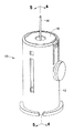
図1を参照すると、使用する前の安全なペンニードルアセンブリ10が示されている。図2によりはっきりと示されるように、組立体10は一般にキャリア12と、ニードル16が固定されたニードルハブ14と、シールド18と、第1の付勢要素20と第2の付勢要素22とを有する。組立体10の構成要素は、図3に示されるように、ニードル16をシールドすることができるように協働するように配置される。
Referring to FIG. 1, a safe
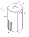
図4〜図10を参照すると、キャリア12は、概ね管状であり遠位端26から近位端28まで延在する側壁24を有する。キャリア12の内部にこれを横切るように係合壁30が配置される。係合壁30の中、好ましくはその中央に開口32が形成される。キャリア12をペン型注射器に取り外し可能に設置させる機構34(例えばねじおよび/またはルアコネクタ)をキャリア12が備えるのが好ましい。この機構34は係合壁30の近位方向に配置されるのがさらに好ましい。
With reference to FIGS. 4-10, the
ニードル16はペン型注射器ニードルであり、患者に注入するための遠位端36を有する。ニードル16はまた、中に含まれる医療内容物へのアクセスを得る目的で、医療用カートリッジの隔壁を突き刺すのに使用することができる反対側の近位端38を有する。ニードル16がニードルハブ14と協調して移動するように、ニードル16がニードルハブ14に固定される。ニードル16が中に設置され固定される(例えば接着剤によって取付けられる)チャネル15(図13および図14)をニードルハブ14の中を貫通して形成することができる。
図5〜図8に最もよく示されるように、ニードルハブ14は、係合壁30の遠位方向に配置される。最初の状態では、図4および図5に示されるように、ニードル16は係合壁30の中に形成された開口32の中を貫通して延出している。最初の状態では、ニードル16の近位端38は、薬剤カートリッジの中への適切なアクセスを得るために薬剤カートリッジ内に十分に挿入されるような位置にある。組立体10を(例えば機構34を使用して)ペン注射器上に設置することによって薬剤カートリッジへのアクセスが得られ、ニードル16の近位端38をペン型注射器の中を近位方向に移動させ、関連するペン型注射器の中に収容された薬剤カートリッジの隔壁を突き刺すようにする。
As best shown in FIGS. 5-8, the
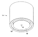
シールド18は、遠位端42および近位端44を有する本体40を含む。シールド18は、ニードル16の遠位端36を選択的に覆うように構成される。組立体10が最初の状態にある図1、図4および図5に示されるように、シールド18はニードル16の遠位端36を覆っていない。シールド18が最初の状態にある場合、遠位端42の中にニードル16が中を通過することを可能にする開口19が形成される。シールド位置にある図3、図6および図7を参照すると、シールド18はニードル16の遠位端36を覆っている。
The
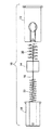
第1の付勢要素20および第2の付勢要素22はそれぞれ、コイルばねまたは圧縮ばねであるのが好ましい。他の既知の付勢要素を本発明と共に使用することもできる。図4および図5を参照すると、ニードルハブ14は最初の位置で示されており、ニードル16は係合壁30の開口32を貫通して延出している。さらに、最初の状態ではシールド18はニードル16の遠位端36を覆っていない。ニードルハブ14を最初の位置から第2のシールド位置に進めるために第1の付勢要素20が配置される。同様にシールド18を最初の位置から第2のシールド位置に進めるために第2の付勢要素22が配置される。図6および図7を参照すると、ニードルハブ14は第2のシールド位置で示されており、ニードル16の近位端38は係合壁30の近位方向に向いた面46の遠位方向に位置している。さらに第2の状態では、シールド18がニードル16の遠位端36を覆っている。このように、ニードル16の遠位端36と近位端38の両方がそれによって不慮にニードルが刺さる可能性を最小限にするために覆われる。
Each of the
好ましい配置では、第1の付勢要素20は、ニードルハブ14を係合壁30から離れるように遠位方向に進めるために係合壁30とニードルハブ14の間に配置される。図14を参照すると、第1の保持溝50を備えてよいニードルハブ14の近位面48が示されている。図4〜図7に示されるように、第1の付勢要素20は第1の保持溝50の中に設置されることが可能である。第1の保持溝50は、第1の付勢要素20に円柱状の剛性を与えることができる。さらにシールド18をニードルハブ14から離れるように遠位方向に進めるために、ニードルハブ14とシールド18の間に第2の付勢要素22を配置することができる。図13を参照すると、ニードルハブ14の遠位面54の中に、第2の付勢要素22を中に設置することができる第2の保持溝52が形成されている。遠位端42から近位方向に延在する保持環56をシールド18上に設けることができる。第2の付勢要素22は保持環56に外接してよい。
In a preferred arrangement, the
ニードルハブ14およびシールド18を図1、図4および図5に示されるように最初の状態に解放可能に保持するために、ロック固定構成を設けるのが好ましい。トリガー作動式のロック固定構成を使用することができ、作動するとニードルハブ14およびシールド18を最初の状態から解放させ、これにより図3、図6および図7に示されるシールド状態に変位することを可能にする手動のトリガーが設けられる。
A locking arrangement is preferably provided to releasably hold the
図面を参照すると、ロック固定構成は、シールド18の本体40から延出するように形成された戻り止め58を有して設けることができる。図4に示されるように、キャリア12の側壁24の中に戻り止め58を入れ子式に収容するように形成されたロック固定開口60が設けられる。戻り止め58およびロック固定開口60は、最初の状態にある組立体10と協働する位置にある。ロック固定開口60は、支点64のところで側壁24に単独で取付けられたトリガーアーム62上に位置している。支点64の近位方向のトリガーアーム62上にトリガーボタン66が位置している。図4の矢印Fによって示されるようにトリガーボタン66に対して加えられる押圧力によって、トリガーボタン66がトリガーアーム62の支点64の近位方向に位置する部分を内側に偏向させ、これによりトリガーアーム62の支点64の遠位方向に位置する部分を外側に偏向させる。したがってトリガーボタン66に対して加えられる押圧力によって、トリガーアーム62を変位させ、その結果ロック固定開口60に戻り止め58を解放させることができる。止め具58とロック固定開口60が相互に係合することによって、第1の付勢要素20および第2の付勢要素22の進める力に逆らってシールド18を最初の状態に保持する保持力が与えられる。戻り止め58を解放することによって、第2の付勢要素22がシールド18を最初の状態からシールド状態に進めることが可能になる。
Referring to the drawings, the locking arrangement can be provided with a
シールド18はまた、最初の状態でニードルハブ14に対して作用する1つまたは複数の停止面68を備えることができる。図4に示されるように、第1の付勢要素20の力を受けてニードルハブ14が最初の状態から遠位方向に移動するのを阻止するために停止面68を設け配置することができる。したがって戻り止め58がロック固定開口60内で受けられる場合、戻り止め58とロック固定開口60が互いに係合することによってニードルハブ14とシールド18両方の移動に対する抵抗をもたらす。戻り止め58とロック固定開口60は、第1の付勢要素20および第2の付勢要素22によって生成される集合的な力に抵抗するように構成される必要がある。
The
組立体10にシールド18をシールド位置にロック固定するためにロック固定構成を設けることがさらに好ましい。図5および図7を参照すると、シールド18は1つまたは複数のロック固定タブ70を備えることができる。キャリア12の側壁24の中に、対応するガイドスロット72が形成される。ガイドスロットによってロック固定タブ70がその中を並進し、シールド18が遠位方向に移動することが可能になる。図7に示されるように、ロック固定タブ70を入れ子式に受けるように形成されたスナップ式のロック固定穴74が、ガイドスロット72の遠位方向に位置している。第2の付勢要素22の力を受けて、ロック固定タブ70がロック固定穴74に嵌るように弾性式に押しやられ、これにより図7に示されるようにシールド18をシールド位置にロック固定することができる。
More preferably, the
ニードルハブ14は、係合壁30から離れるようにニードルハブ14を進める第1の付勢要素20によってシールド位置にロック固定される必要はない。第1の付勢要素20の力を受けたニードルハブの許容できる遠位方向の移動を制限するために、側壁24から内側に向かって1つまたは複数の境界76が延在してよい。図6に示されるように、境界76は、ニードル16の近位端38が係合壁30の近位方向に向いた面46の遠位方向に位置するように、ニードルハブ14を遠位方向に十分移動させることができるように配置されている。境界76を受けるためにシールド18内にバイパススロット78が形成される。このバイパススロット78によって、境界76に邪魔されずにシールド18が並進することが可能になる。
シールド18は、ニードルハブ14がその最初の状態から遠位方向に再配置された場合シールド位置でニードル16の遠位端36を覆うように形成され配置される必要があることも理解される。換言するとニードル16の遠位端36は、最初の位置よりも係合壁30からさらに遠位方向に位置している。
It will also be appreciated that the
Claims (4)
遠位端、近位端、および前記近位端と前記遠位端の間に固定的に位置する横断係合壁を有し、前記係合壁が近位方向に向いた外面および前記係合壁を貫通するように形成された開口とを有する管状のキャリアと、
患者に注入するための遠位端および近位端を有するニードルと、
前記ニードルがニードルハブと共に移動するようにニードルハブに固定され、前記係合壁の遠位方向で前記キャリアの中に解放可能に保持されるニードルハブと、
前記ニードルの前記遠位端を選択的に覆うシールドと、
前記ニードルが前記係合壁の前記開口を貫通して延出する第1のハブ位置から、前記ニードルの前記近位端が前記係合壁の前記近位方向に向いた外面の遠位方向に位置する第2のハブ位置に前記ニードルハブを進めるための第1の付勢手段と、
前記ニードルの前記遠位端が前記シールドによって覆われていない第1のシールド位置から、前記ニードルの前記遠位端が前記シールドによって覆われる第2のシールド位置へ前記シールドを、前記管状のキャリアに対して進めるための第2の付勢手段と、
を備えることを特徴とする組立体。 A safe pen needle assembly,
A distal end, a proximal end, and a transverse engagement wall fixedly positioned between the proximal end and the distal end, wherein the engagement wall is a proximally directed outer surface and the engagement A tubular carrier having an opening formed to penetrate the wall;
A needle having a distal end and a proximal end for injecting into a patient;
A needle hub secured to the needle hub such that the needle moves with the needle hub and releasably retained in the carrier in a distal direction of the engagement wall;
A shield that selectively covers the distal end of the needle;
From a first hub position where the needle extends through the opening in the engagement wall, the proximal end of the needle is in the distal direction of the outer surface of the engagement wall facing the proximal direction. First biasing means for advancing the needle hub to a second hub position located;
The shield on the tubular carrier from a first shield position where the distal end of the needle is not covered by the shield to a second shield position where the distal end of the needle is covered by the shield A second biasing means for proceeding against,
An assembly comprising:
Applications Claiming Priority (3)
| Application Number | Priority Date | Filing Date | Title |
|---|---|---|---|
| US2913308P | 2008-02-15 | 2008-02-15 | |
| US61/029,133 | 2008-02-15 | ||
| PCT/US2009/033204 WO2009102612A1 (en) | 2008-02-15 | 2009-02-05 | Safety pen needle assembly |
Related Child Applications (1)
| Application Number | Title | Priority Date | Filing Date |
|---|---|---|---|
| JP2016119337A Division JP6374441B2 (en) | 2008-02-15 | 2016-06-15 | Safe pen needle assembly |
Publications (2)
| Publication Number | Publication Date |
|---|---|
| JP2011512196A JP2011512196A (en) | 2011-04-21 |
| JP6017760B2 true JP6017760B2 (en) | 2016-11-02 |
Family
ID=40590022
Family Applications (2)
| Application Number | Title | Priority Date | Filing Date |
|---|---|---|---|
| JP2010546832A Active JP6017760B2 (en) | 2008-02-15 | 2009-02-05 | Safe pen needle assembly |
| JP2016119337A Active JP6374441B2 (en) | 2008-02-15 | 2016-06-15 | Safe pen needle assembly |
Family Applications After (1)
| Application Number | Title | Priority Date | Filing Date |
|---|---|---|---|
| JP2016119337A Active JP6374441B2 (en) | 2008-02-15 | 2016-06-15 | Safe pen needle assembly |
Country Status (5)
| Country | Link |
|---|---|
| US (1) | US8840590B2 (en) |
| EP (1) | EP2247328B1 (en) |
| JP (2) | JP6017760B2 (en) |
| CA (1) | CA2714621C (en) |
| WO (1) | WO2009102612A1 (en) |
Cited By (1)
| Publication number | Priority date | Publication date | Assignee | Title |
|---|---|---|---|---|
| WO2018131809A1 (en) * | 2017-01-14 | 2018-07-19 | 최규동 | Safety pen needle structure for preventing reuse |
Families Citing this family (22)
| Publication number | Priority date | Publication date | Assignee | Title |
|---|---|---|---|---|
| US8876781B2 (en) * | 2009-06-18 | 2014-11-04 | Shl Group Ab | Safety pen needle device |
| JP5657786B2 (en) * | 2010-05-26 | 2015-01-21 | ベクトン・ディキンソン・アンド・カンパニーBecton, Dickinson And Company | Safety needle assembly |
| ES2863959T3 (en) * | 2013-12-10 | 2021-10-13 | Becton Dickinson Co | Active Safety Pen Needle Assembly |
| US9623194B2 (en) | 2013-12-10 | 2017-04-18 | Becton, Dickinson And Company | Passive safety pen needle assembly |
| US10350369B2 (en) | 2014-01-06 | 2019-07-16 | Novo Nordisk A/S | Shielding mechanism for an injection apparatus |
| USD768852S1 (en) | 2014-06-30 | 2016-10-11 | Htl-Strefa Spolka Akcyjna | Safety needle device |
| USD768851S1 (en) | 2014-06-30 | 2016-10-11 | Htl-Strefa Spolka Akcyjna | Safety needle device |
| CN104338215B (en) * | 2014-11-04 | 2017-02-01 | 贝普医疗科技有限公司 | Disposable use safe self-destruction insulin needle |
| GB201507981D0 (en) * | 2015-05-11 | 2015-06-24 | Owen Mumford Ltd | Needle assemblies |
| KR101589006B1 (en) | 2015-10-17 | 2016-02-12 | 주식회사 메덱셀 | Safety protection system for pen needles |
| EP3243539B1 (en) * | 2016-05-11 | 2020-04-08 | Becton, Dickinson and Company | Safety module for insertion needle |
| USD938022S1 (en) * | 2016-08-10 | 2021-12-07 | Owen Mumford Limited | Safety pen needle |
| USD847981S1 (en) * | 2016-08-10 | 2019-05-07 | Owen Mumford Limited | Safety pen needle |
| US11260173B2 (en) * | 2016-09-15 | 2022-03-01 | Becton, Dickinson And Company | Needle assembly for subcutaneous infusion set |
| JP1576173S (en) * | 2016-10-14 | 2020-05-11 | ||
| GB2560556A (en) | 2017-03-15 | 2018-09-19 | Owen Mumford Ltd | A Needle cover |
| CN111225700A (en) * | 2017-10-06 | 2020-06-02 | 诺信公司 | Tamper-evident closure assembly |
| GB201906918D0 (en) * | 2019-05-16 | 2019-07-03 | Owen Mumford Ltd | Pen needle |
| USD914208S1 (en) | 2019-06-14 | 2021-03-23 | Owen Mumford Limited | Syringe component |
| TWD206925S (en) | 2019-06-14 | 2020-09-01 | 英商歐恩.曼佛爾德股份有限公司 | Syringe |
| USD959651S1 (en) | 2020-04-08 | 2022-08-02 | Owen Mumford Limited | Medical instrument |
| USD972745S1 (en) | 2020-05-07 | 2022-12-13 | Owen Mumford Limited | Testing device |
Family Cites Families (7)
| Publication number | Priority date | Publication date | Assignee | Title |
|---|---|---|---|---|
| US4921491A (en) * | 1989-04-03 | 1990-05-01 | Champ Raynido A | Disposable needle system with chemical disinfectant means |
| ES2015427A6 (en) | 1989-07-21 | 1990-08-16 | Sempere Escudero Philippe | A safety protective device for injection needles. |
| FR2654346A1 (en) | 1989-11-10 | 1991-05-17 | Laisne Maurice | Syringe which can be used only once and which has an incorporated and sliding system for protecting the needle |
| US5964739A (en) * | 1998-06-18 | 1999-10-12 | Champ; Raynido A. | Safety disposable needle structure |
| US6986760B2 (en) * | 2000-08-02 | 2006-01-17 | Becton, Dickinson And Company | Pen needle and safety shield system |
| AT413648B (en) * | 2002-10-02 | 2006-04-15 | Greiner Bio One Gmbh | RECORDING DEVICE WITH ADJUSTABLE COVERING ELEMENT |
| US7540858B2 (en) * | 2007-01-23 | 2009-06-02 | Becton, Dickinson And Company | Retracting safety pen needle |
-
2009
- 2009-02-05 US US12/866,779 patent/US8840590B2/en active Active
- 2009-02-05 JP JP2010546832A patent/JP6017760B2/en active Active
- 2009-02-05 WO PCT/US2009/033204 patent/WO2009102612A1/en active Application Filing
- 2009-02-05 EP EP09709630.9A patent/EP2247328B1/en active Active
- 2009-02-05 CA CA2714621A patent/CA2714621C/en active Active
-
2016
- 2016-06-15 JP JP2016119337A patent/JP6374441B2/en active Active
Cited By (1)
| Publication number | Priority date | Publication date | Assignee | Title |
|---|---|---|---|---|
| WO2018131809A1 (en) * | 2017-01-14 | 2018-07-19 | 최규동 | Safety pen needle structure for preventing reuse |
Also Published As
| Publication number | Publication date |
|---|---|
| CA2714621A1 (en) | 2009-08-20 |
| US20110178473A1 (en) | 2011-07-21 |
| EP2247328B1 (en) | 2018-11-07 |
| JP2016179226A (en) | 2016-10-13 |
| EP2247328A1 (en) | 2010-11-10 |
| CA2714621C (en) | 2017-08-15 |
| US8840590B2 (en) | 2014-09-23 |
| JP6374441B2 (en) | 2018-08-15 |
| JP2011512196A (en) | 2011-04-21 |
| WO2009102612A1 (en) | 2009-08-20 |
Similar Documents
| Publication | Publication Date | Title |
|---|---|---|
| JP6374441B2 (en) | Safe pen needle assembly | |
| CA2873681C (en) | Passive safety pen needle assembly | |
| EP2853277B1 (en) | Prefilled safety pen needle | |
| US8632503B2 (en) | Safety pen needle assembly having shielding for patient and non-patient ends | |
| JP6693696B2 (en) | Active safety pen needle assembly | |
| EP2262559B1 (en) | Safety pen needle assembly having shield for non-patient end | |
| US20210361874A1 (en) | Medicament delivery device and method of assembling the same | |
| JP2014526356A (en) | Needle safety device | |
| JP5657786B2 (en) | Safety needle assembly | |
| JP2017508514A (en) | Automatic injection device | |
| JP6125513B2 (en) | Needle safety device | |
| JP6294338B2 (en) | Safety blood collection device activated by a passive dual drive member |
Legal Events
| Date | Code | Title | Description |
|---|---|---|---|
| A621 | Written request for application examination |
Free format text: JAPANESE INTERMEDIATE CODE: A621 Effective date: 20120111 |
|
| A977 | Report on retrieval |
Free format text: JAPANESE INTERMEDIATE CODE: A971007 Effective date: 20130221 |
|
| A131 | Notification of reasons for refusal |
Free format text: JAPANESE INTERMEDIATE CODE: A131 Effective date: 20130222 |
|
| A601 | Written request for extension of time |
Free format text: JAPANESE INTERMEDIATE CODE: A601 Effective date: 20130522 |
|
| A521 | Request for written amendment filed |
Free format text: JAPANESE INTERMEDIATE CODE: A523 Effective date: 20130529 |
|
| A602 | Written permission of extension of time |
Free format text: JAPANESE INTERMEDIATE CODE: A602 Effective date: 20130529 |
|
| A601 | Written request for extension of time |
Free format text: JAPANESE INTERMEDIATE CODE: A601 Effective date: 20140205 |
|
| A602 | Written permission of extension of time |
Free format text: JAPANESE INTERMEDIATE CODE: A602 Effective date: 20140213 |
|
| A601 | Written request for extension of time |
Free format text: JAPANESE INTERMEDIATE CODE: A601 Effective date: 20140305 |
|
| A602 | Written permission of extension of time |
Free format text: JAPANESE INTERMEDIATE CODE: A602 Effective date: 20140312 |
|
| A521 | Request for written amendment filed |
Free format text: JAPANESE INTERMEDIATE CODE: A523 Effective date: 20140402 |
|
| A02 | Decision of refusal |
Free format text: JAPANESE INTERMEDIATE CODE: A02 Effective date: 20140924 |
|
| A521 | Request for written amendment filed |
Free format text: JAPANESE INTERMEDIATE CODE: A523 Effective date: 20150126 |
|
| A911 | Transfer to examiner for re-examination before appeal (zenchi) |
Free format text: JAPANESE INTERMEDIATE CODE: A911 Effective date: 20150203 |
|
| A912 | Re-examination (zenchi) completed and case transferred to appeal board |
Free format text: JAPANESE INTERMEDIATE CODE: A912 Effective date: 20150424 |
|
| A521 | Request for written amendment filed |
Free format text: JAPANESE INTERMEDIATE CODE: A523 Effective date: 20160615 |
|
| A61 | First payment of annual fees (during grant procedure) |
Free format text: JAPANESE INTERMEDIATE CODE: A61 Effective date: 20160929 |
|
| R150 | Certificate of patent or registration of utility model |
Ref document number: 6017760 Country of ref document: JP Free format text: JAPANESE INTERMEDIATE CODE: R150 |
|
| R250 | Receipt of annual fees |
Free format text: JAPANESE INTERMEDIATE CODE: R250 |
|
| R250 | Receipt of annual fees |
Free format text: JAPANESE INTERMEDIATE CODE: R250 |
|
| R250 | Receipt of annual fees |
Free format text: JAPANESE INTERMEDIATE CODE: R250 |
|
| S111 | Request for change of ownership or part of ownership |
Free format text: JAPANESE INTERMEDIATE CODE: R313113 |
|
| R350 | Written notification of registration of transfer |
Free format text: JAPANESE INTERMEDIATE CODE: R350 |
|
| R250 | Receipt of annual fees |
Free format text: JAPANESE INTERMEDIATE CODE: R250 |