JP6017705B2 - Security camera with dual communication port - Google Patents
Security camera with dual communication port Download PDFInfo
- Publication number
- JP6017705B2 JP6017705B2 JP2015551937A JP2015551937A JP6017705B2 JP 6017705 B2 JP6017705 B2 JP 6017705B2 JP 2015551937 A JP2015551937 A JP 2015551937A JP 2015551937 A JP2015551937 A JP 2015551937A JP 6017705 B2 JP6017705 B2 JP 6017705B2
- Authority
- JP
- Japan
- Prior art keywords
- primary
- communication port
- phy
- security camera
- secondary communication
- Prior art date
- Legal status (The legal status is an assumption and is not a legal conclusion. Google has not performed a legal analysis and makes no representation as to the accuracy of the status listed.)
- Active
Links
Images


Classifications
-
- G—PHYSICS
- G06—COMPUTING; CALCULATING OR COUNTING
- G06F—ELECTRIC DIGITAL DATA PROCESSING
- G06F3/00—Input arrangements for transferring data to be processed into a form capable of being handled by the computer; Output arrangements for transferring data from processing unit to output unit, e.g. interface arrangements
- G06F3/002—Specific input/output arrangements not covered by G06F3/01 - G06F3/16
- G06F3/005—Input arrangements through a video camera
-
- H—ELECTRICITY
- H04—ELECTRIC COMMUNICATION TECHNIQUE
- H04N—PICTORIAL COMMUNICATION, e.g. TELEVISION
- H04N7/00—Television systems
- H04N7/18—Closed-circuit television [CCTV] systems, i.e. systems in which the video signal is not broadcast
-
- H—ELECTRICITY
- H04—ELECTRIC COMMUNICATION TECHNIQUE
- H04N—PICTORIAL COMMUNICATION, e.g. TELEVISION
- H04N23/00—Cameras or camera modules comprising electronic image sensors; Control thereof
- H04N23/50—Constructional details
-
- H—ELECTRICITY
- H04—ELECTRIC COMMUNICATION TECHNIQUE
- H04N—PICTORIAL COMMUNICATION, e.g. TELEVISION
- H04N23/00—Cameras or camera modules comprising electronic image sensors; Control thereof
- H04N23/50—Constructional details
- H04N23/51—Housings
-
- H—ELECTRICITY
- H04—ELECTRIC COMMUNICATION TECHNIQUE
- H04N—PICTORIAL COMMUNICATION, e.g. TELEVISION
- H04N23/00—Cameras or camera modules comprising electronic image sensors; Control thereof
- H04N23/60—Control of cameras or camera modules
- H04N23/66—Remote control of cameras or camera parts, e.g. by remote control devices
- H04N23/661—Transmitting camera control signals through networks, e.g. control via the Internet
Description
本開示は、二重通信ポートを有する防犯カメラに関する。 The present disclosure relates to a security camera having a dual communication port.
保安警備業界、特にインターネットプロトコル(IP)防犯カメラの市場は成長を続けている。これは一部には、IP防犯カメラの、従来のアナログ防犯カメラに比べて得られる利点によるものである。例えば、IPカメラは、双方向通信が可能であり、アナログカメラより高い解像度を可能とし、IPネットワーク上で容易に再配置することができる。その普及が進めば、研究開発は、IP防犯カメラの設置及び使用をより容易にすることへと続いていく。 The security industry, especially the Internet Protocol (IP) security camera market, continues to grow. This is due in part to the advantages of IP security cameras over traditional analog security cameras. For example, an IP camera is capable of two-way communication, enables higher resolution than an analog camera, and can be easily relocated on an IP network. As its spread progresses, research and development will continue to make it easier to install and use IP security cameras.
本発明の第1の態様によれば、二重通信ポートを有する防犯カメラが提供される。カメラは、光がカメラ本体に進入するのを可能にする開口部を含む、装着面に装着可能なカメラ本体と、カメラ本体に搭載され、開口部を通ってカメラ本体に進入する光を屈折させるように位置決めされたレンズと、カメラ本体内に配置され、レンズによって屈折された光を受けるように位置決めされたイメージャと、カメラ本体の外部からアクセス可能な一次通信ポートを含み、一次通信ポートが、カメラ本体が装着された場合に前記装着面の片側に配置される、一次通信回路と、カメラ本体の外部からアクセス可能な二次通信ポートを含み、二次通信ポート並びにレンズ及び開口部の一方又は両方が、カメラ本体が装着された場合に前記装着面の反対側に配置される、二次通信回路と、イメージャ並びに一次及び二次通信回路に通信可能に結合する制御及び処理回路であって、プロセッサと、プロセッサに通信可能に結合し、二次通信ポートがアクティブリンクに結合している場合に、プロセッサに、イメージャ上に入射した光から得られたデジタル通信信号を二次通信ポートに送信させる、コード化されたステートメント及び命令を有するコンピュータ可読媒体とを含む、制御及び処理回路と、を含む。 According to a first aspect of the present invention, a security camera having a dual communication port is provided. The camera includes an opening that allows light to enter the camera body, a camera body that can be mounted on the mounting surface, and is mounted on the camera body and refracts light that enters the camera body through the opening. A lens positioned in such a manner, an imager positioned within the camera body and positioned to receive light refracted by the lens, and a primary communication port accessible from outside the camera body, the primary communication port comprising: A primary communication circuit disposed on one side of the mounting surface when the camera body is mounted, and a secondary communication port accessible from the outside of the camera body, the secondary communication port and one of the lens and the opening or Both can communicate with the secondary communication circuit, the imager, and the primary and secondary communication circuits that are placed on the opposite side of the mounting surface when the camera body is mounted Control and processing circuitry that couples to the processor and digitally derived from light incident on the imager when the secondary communication port is coupled to the active link when communicatively coupled to the processor Control and processing circuitry including computer readable media having coded statements and instructions for causing communication signals to be transmitted to the secondary communication port.
別の態様によれば、二重通信ポートを有する防犯カメラが提供される。カメラは、光が前記カメラ本体に進入するのを可能にする開口部を含むカメラ本体と、カメラ本体に搭載され、開口部を通って前記カメラ本体に進入する光を屈折させるように位置決めされたレンズと、カメラ本体内に配置され、レンズによって屈折された光を受けるように位置決めされたイメージャと、カメラ本体に取付けられ、装着面に装着可能な取付組立体と、取付組立体を通してアクセス可能な一次通信ポートを含む一次通信回路と、カメラ本体を通してアクセス可能な二次通信ポートを含む二次通信回路と、イメージャ並びに一次及び二次通信回路に通信可能に結合する制御及び処理回路であって、プロセッサと、プロセッサに通信可能に結合し、二次通信ポートがアクティブリンクに結合している場合に、プロセッサに、イメージャ上に入射した光から得られるデジタル通信信号を二次通信ポートに送信させる、コード化されたステートメント及び命令を有するコンピュータ可読媒体とを含む、制御及び処理回路と、を含む。取付組立体は、取付板に固定された装着アームを含むことができ、取付板は、アクセスポートを含むことができ、該アクセスポートを通して一次通信ポートにアクセス可能である。アクセスポートは、カメラが装着された場合に装着面に隣接する取付板の面上に配置することができる。 According to another aspect, a security camera having a dual communication port is provided. The camera is mounted on the camera body including an opening that allows light to enter the camera body, and is positioned to refract the light entering the camera body through the opening. A lens, an imager positioned within the camera body and positioned to receive light refracted by the lens, a mounting assembly attached to the camera body and attachable to the mounting surface, and accessible through the mounting assembly A primary communication circuit including a primary communication port; a secondary communication circuit including a secondary communication port accessible through the camera body; and a control and processing circuit communicatively coupled to the imager and the primary and secondary communication circuits, If the processor is communicatively coupled to the processor and the secondary communication port is coupled to the active link, the processor The digital communication signals obtained from the light incident on the catcher is transmitted to the secondary communication port, and a computer-readable medium having encoded statements and instructions, including control and a processing circuit. The mounting assembly can include a mounting arm that is secured to the mounting plate, and the mounting plate can include an access port through which the primary communication port is accessible. The access port can be disposed on the surface of the mounting plate adjacent to the mounting surface when the camera is mounted.
別の態様によれば、二重通信ポートを有する防犯カメラが提供され、該カメラは、光が前記カメラ本体に進入するのを可能にする開口部を含む、装着面に装着可能なカメラ本体と、カメラ本体に搭載され、開口部を通ってカメラ本体に進入する光を屈折させるように位置決めされたレンズと、カメラ本体内に配置され、レンズによって屈折された光を受けるように位置決めされたイメージャと、カメラ本体の外部からアクセス可能な一次通信ポートを含み、一次通信ポートが、カメラ本体が装着された場合に装着面の裏側に配置される一次通信回路と、カメラ本体の外部からアクセス可能な二次通信ポートを含み、二次通信ポートが、カメラ本体が装着された場合に装着面の前側に配置される、二次通信回路と、イメージャ並びに一次及び二次通信回路に通信可能に結合する制御及び処理回路であって、プロセッサと、プロセッサに通信可能に結合し、二次通信ポートがアクティブリンクに結合している場合に、プロセッサに、イメージャ上に入射した光から得られるデジタル通信信号を二次通信ポートに送信させる、コード化されたステートメント及び命令を有するコンピュータ可読媒体とを含む、制御及び処理回路と、を含む。 According to another aspect, a security camera having a dual communication port is provided, the camera including an opening that allows light to enter the camera body, and a camera body attachable to a mounting surface; A lens mounted on the camera body and positioned to refract the light entering the camera body through the opening, and an imager positioned within the camera body and positioned to receive the light refracted by the lens And a primary communication port accessible from the outside of the camera body, the primary communication port being accessible from the outside of the camera body, and a primary communication circuit disposed on the back side of the mounting surface when the camera body is attached Including a secondary communication port, and the secondary communication port is disposed on the front side of the mounting surface when the camera body is mounted, the imager, and the primary and secondary A control and processing circuit communicatively coupled to a communication circuit, wherein the processor is communicatively coupled to the processor and the secondary communication port is coupled to the active link and incident on the processor on the imager Control and processing circuitry including computer readable media having encoded statements and instructions for causing a digital communication signal derived from light to be transmitted to a secondary communication port.
以下、上述の態様の全てに対する可能性のある変形を説明する。 In the following, possible modifications to all of the above aspects will be described.
デジタル通信信号は、一次及び二次通信ポートの両方に同時に送信されるものとすることができる。 Digital communication signals may be sent simultaneously to both the primary and secondary communication ports.
あるいは、デジタル通信信号は、一次通信ポート又は二次通信ポートに別々に送信されるものとすることができる。 Alternatively, the digital communication signal may be transmitted separately to the primary communication port or the secondary communication port.
前記ステートメント及び命令はさらに、プロセッサに、二次通信ポートがアクティブリンクに結合しているか否かを検出させ、二次通信ポートがアクティブリンクに結合している場合にのみ二次通信ポートにデジタル通信信号を送信させることができる。 The statements and instructions further cause the processor to detect whether the secondary communication port is coupled to the active link, and digitally communicates to the secondary communication port only when the secondary communication port is coupled to the active link. A signal can be transmitted.
二次通信ポートがアクティブリンクに結合しているか否かを検出することは、二次通信ポートをポーリングすることを含むことができる。 Detecting whether the secondary communication port is coupled to the active link can include polling the secondary communication port.
ステートメント及び命令はさらに、プロセッサに、二次通信ポートがアクティブリンクに結合していない場合に、デジタル通信信号を一次通信ポートに送信させることができる。 The statements and instructions can further cause the processor to send a digital communication signal to the primary communication port when the secondary communication port is not coupled to an active link.
二次通信ポートは、カメラ本体の底面に位置することができる。 The secondary communication port can be located on the bottom surface of the camera body.
デジタル通信信号は、イーサネットを用いて通信することができる。 Digital communication signals can be communicated using Ethernet.
制御及び処理回路は、媒体アクセスコントローラ(MAC)及び入力/出力制御回路をさらに含むことができ、それらの各々が、前記プロセッサ、並びに前記一次及び二次通信回路に通信可能に結合する。 The control and processing circuitry may further include a media access controller (MAC) and input / output control circuitry, each of which is communicatively coupled to the processor and the primary and secondary communication circuitry.
一次通信回路は、一次通信ポート及びMACに通信可能に結合した一次PHYを含むことができ、二次通信回路は、二次通信ポート及びMACに通信可能に結合した二次PHYを含むことができる。 The primary communication circuit can include a primary PHY that is communicatively coupled to the primary communication port and the MAC, and the secondary communication circuit can include a secondary PHY that is communicatively coupled to the secondary communication port and the MAC. .
一次及び二次PHYは、MACの共有媒体非依存インタフェース(MIIバス)及び共有管理データ入力/出力インタフェース(MDIOバス)を通じてMACに通信可能に結合することができる。 The primary and secondary PHYs can be communicatively coupled to the MAC through the MAC's shared media independent interface (MII bus) and shared management data input / output interface (MDIO bus).
一次及び二次PHYは、MIIバスに接続されたそれらの出力を高インピーダンス状態に設定することによって動作を開始するようにピン・ストラップすることができる。 The primary and secondary PHYs can be pin strapped to start operation by setting their outputs connected to the MII bus to a high impedance state.
入力/出力回路は、一次PHYに通信可能に結合された一次リセットラインと、二次PHYのリセット入力に通信可能に結合された二次リセットラインと、一次及び二次PHY上のMDIOアドレス選択入力に通信可能に結合されたアドレスラインとを含むことができる。 The input / output circuit includes a primary reset line communicatively coupled to the primary PHY, a secondary reset line communicatively coupled to the reset input of the secondary PHY, and MDIO address select inputs on the primary and secondary PHYs And address lines communicatively coupled to each other.
ステートメント及び命令はさらに、プロセッサに、二次通信ポートがアクティブリンクに結合していることを検出する前に、一次通信ポートに一次PHYを介してデジタル通信信号を送信させ、及び、MIIバスに接続した二次PHYの出力を高インピーダンス状態に設定させ、並びに二次通信ポートがアクティブリンクに結合していることを検出した後に、一次PHYを停止させ、二次PHYを作動させる前にアクティブリンクが存在しないことをアプリケーション層に通知させ、MIIバスに接続した一次PHYの出力を高インピーダンス状態に設定させ、MIIバスに接続した二次PHYの出力を高インピーダンス状態から解除し、二次PHYを作動させ、及び、アクティブリンクが存在することをアプリケーション層に通知させることができる。 The statements and instructions further cause the processor to transmit a digital communication signal over the primary PHY and connect to the MII bus before detecting that the secondary communication port is coupled to the active link. The secondary PHY output is set to a high impedance state, and after detecting that the secondary communication port is coupled to the active link, the active link is deactivated before the primary PHY is stopped and the secondary PHY is activated. Notify the application layer that it does not exist, set the output of the primary PHY connected to the MII bus to the high impedance state, release the output of the secondary PHY connected to the MII bus from the high impedance state, and activate the secondary PHY And notify the application layer that an active link exists. Can.
カメラは、弾丸型カメラとすることができる。 The camera can be a bullet camera.
別の態様によれば、装着面に装着可能なカメラ本体と、光がカメラ本体に進入するのを可能にするカメラ本体内の開口部と、カメラ本体に搭載され、開口部を通ってカメラ本体に進入する光を屈折させるように位置決めされたレンズと、カメラ本体内に配置され、レンズによって屈折された光を受けるように位置決めされたイメージャとを含む防犯カメラの、一次通信ポートと二次通信ポートとの間で切り換えるための方法が提供され、一次通信ポートは、カメラ本体が装着された場合に装着面の片側に配置され、二次通信ポート、並びにレンズ及び開口部の一方又は両方が、カメラ本体が装着された場合に装着面の反対側に配置される。この方法は、二次通信ポートがアクティブリンクに結合している場合に、イメージャ上に入射した光から得られる映像信号を含むデジタル通信信号を二次通信ポートに送信することを含む。 According to another aspect, a camera body that can be mounted on the mounting surface, an opening in the camera body that allows light to enter the camera body, and the camera body that is mounted on the camera body and passes through the opening. Primary communication port and secondary communication of a security camera including a lens positioned to refract light entering the camera and an imager positioned within the camera body and positioned to receive light refracted by the lens A method is provided for switching to and from the port, the primary communication port is located on one side of the mounting surface when the camera body is mounted, the secondary communication port, and one or both of the lens and the aperture, When the camera body is mounted, it is arranged on the opposite side of the mounting surface. The method includes transmitting a digital communication signal including a video signal obtained from light incident on the imager to the secondary communication port when the secondary communication port is coupled to an active link.
デジタル通信信号は、一次及び二次通信ポートの両方に同時に送信されるものとすることができる。あるいは、デジタル通信信号は、一次通信ポート又は前記二次通信ポートに別々に送信されるものとすることができる。 Digital communication signals may be sent simultaneously to both the primary and secondary communication ports. Alternatively, the digital communication signal may be transmitted separately to the primary communication port or the secondary communication port.
この方法は、二次通信ポートがアクティブリンクに結合しているか否かを検出することと、二次通信ポートがアクティブリンクに結合している場合にのみ二次通信ポートにデジタル通信信号を送信することとをさらに含むことができる。 This method detects whether the secondary communication port is coupled to the active link, and transmits a digital communication signal to the secondary communication port only when the secondary communication port is coupled to the active link. Can be further included.
二次通信ポートがアクティブリンクに結合しているか否かを検出することは、二次通信ポートをポーリングすることを含むことができる。 Detecting whether the secondary communication port is coupled to the active link can include polling the secondary communication port.
この方法は、二次通信ポートがアクティブリンクに結合していない場合に、デジタル通信信号を一次通信ポートに送信することをさらに含むことができる。 The method can further include transmitting a digital communication signal to the primary communication port when the secondary communication port is not coupled to the active link.
二次通信ポートは、カメラ本体の底面に位置するものとすることができる。 The secondary communication port may be located on the bottom surface of the camera body.
デジタル通信信号は、イーサネットを用いて通信することができる。 Digital communication signals can be communicated using Ethernet.
カメラは、媒体非依存インタフェース(MII)バス並びに一次PHY及び二次PHYをさらに含むことができ、それらPHYの各々が、MIIバスに接続された出力を有し、それを介してデジタル通信信号が一次及び二次通信ポートに送信され、この方法は、二次通信ポートがアクティブリンクに結合していることを検出する前に、一次通信ポートに一次PHYを介してデジタル通信信号を送信すること、及び、MIIバスに接続した二次PHYの出力を高インピーダンス状態に設定すること、並びに二次通信ポートがアクティブリンクに結合していることを検出した後に、一次PHYを停止すること、二次PHYを作動させる前にアクティブリンクが存在しないことをアプリケーション層に通知すること、MIIバスに接続した一次PHYの出力を高インピーダンス状態に設定すること、MIIバスに接続した二次PHYの出力を高インピーダンス状態から解除すること、二次PHYを作動させること、及び、アクティブリンクが存在することをアプリケーション層に通知すること、をさらに含むことができる。 The camera can further include a media independent interface (MII) bus and primary and secondary PHYs, each of which has an output connected to the MII bus, through which digital communication signals are transmitted. Transmitted to the primary and secondary communication ports, the method transmitting a digital communication signal to the primary communication port via the primary PHY before detecting that the secondary communication port is coupled to the active link; And setting the output of the secondary PHY connected to the MII bus to a high impedance state, and stopping the primary PHY after detecting that the secondary communication port is coupled to the active link, the secondary PHY To notify the application layer that there is no active link before activating the primary PH connected to the MII bus To the application layer that sets the output of the secondary PHY connected to the MII bus from the high impedance state, activates the secondary PHY, and that an active link exists. Can be further included.
カメラは、弾丸型カメラとすることができる。 The camera can be a bullet camera.
別の態様によれば、前述の方法の態様又はそれらの組合せのいずれかをプロセッサに実行させるコード化されたステートメント及び命令を有する、非一時的なコンピュータ可読媒体が提供される。 According to another aspect, a non-transitory computer readable medium having encoded statements and instructions that cause a processor to perform any of the foregoing method aspects or combinations thereof is provided.
この要旨は、必ずしも全ての態様の全範囲を記載してない。他の態様、特徴及び利点は、当業者には、下の特定の実施形態の説明を検討すれば明らかである。 This summary does not necessarily describe the full scope of all embodiments. Other aspects, features, and advantages will be apparent to those skilled in the art upon review of the description of particular embodiments below.
添付の図面は、1つ又はそれ以上の例示的な実施形態を示す。 The accompanying drawings illustrate one or more exemplary embodiments.
「上」、「底」、「上方」、「下方」、「縦」及び「横」などの方向を示す用語は、以下の説明中、相対的な基準を与える目的のみで用いられ、いずれかの物品を使用中にどのように配置するか、又は組立体の中に若しくは環境に対してどのように装着するかに関してなんら制限を示唆することを意図したものではない。 The terms indicating directions such as “top”, “bottom”, “upward”, “downward”, “vertical” and “horizontal” are used in the following description only for the purpose of providing a relative standard. It is not intended to suggest any limitation as to how the item is placed in use or how it is mounted in the assembly or to the environment.
従来のIP防犯カメラの設置の際、設置技術者は、カメラをネットワークに接続し、このネットワークを介して、カメラは、映像を生成するために用いられるデジタル映像情報及び制御情報を含むデジタル通信信号を伝送する。カメラとネットワークとの間の接続部(「ネットワーク接続」)は、カメラが装着される面(「装着面」)の裏側にあり、例えば装着面が壁である場合、ネットワーク接続は壁の裏側で行われる。このネットワーク接続の位置は、カメラを所定位置に配置して装着面に固定すると、技術者はもはやネットワーク接続に物理的にアクセスすることができないことを意味する。 When installing a conventional IP security camera, an installation engineer connects the camera to a network, through which the camera communicates digital communication signals including digital video information and control information used to generate video. Is transmitted. The connection between the camera and the network (“network connection”) is on the back side of the surface on which the camera is mounted (“mounting surface”). For example, if the mounting surface is a wall, the network connection is Done. This network connection location means that once the camera is in place and secured to the mounting surface, the technician can no longer physically access the network connection.
カメラが装着されると、設置プロセスは、カメラの焦点及び照準を適切に合わせるために、技術者が、カメラがネットワークに出力するデジタル通信信号から生成される映像を見ることを必要とする。しかしながら、技術者はネットワーク接続にアクセスできないので、技術者は、ネットワークに接続された、カメラから遠隔にある映像端末からの映像を直接見るか、又は映像端末のところにいて技術者に情報を中継する協力者と共に作業するか、そのどちらかである。どちらの解決策も最適ではなく、前者の場合、技術者がカメラと映像端末との間で移動する時間が無駄であり、他方、後者の場合、技術者が一人で作業する場合よりも人件費がかかる。 Once the camera is installed, the installation process requires the technician to view the video generated from the digital communication signals that the camera outputs to the network in order to properly focus and aim the camera. However, since the technician cannot access the network connection, the technician can directly view the video from the video terminal connected to the network and remote from the camera, or relay information to the technician at the video terminal. Work with collaborators, or either. Neither solution is optimal, and in the former case, the technician has to waste time moving between the camera and the video terminal, whereas in the latter case, the labor cost is higher than when the technician works alone. It takes.
本明細書で開示される実施形態は、デジタル通信信号を出力するために用いられる二重通信ポートを有する防犯カメラに関する。通信ポートの一方(「一次通信ポート」)は、カメラが設置される場合に装着面の裏側に配置され、もう一方(「二次通信ポート」)は、装着面の前側に配置され、カメラが装着された後でも技術者がアクセス可能である。技術者が映像端末を二次通信ポートに接続すると、カメラは、技術者の映像端末にデジタル通信信号を出力し、技術者が一人で作業している場合にカメラから離れなくても映像を見ること並びにカメラの焦点及び照準を合わせることを可能にし、これによりカメラの設置が容易になる。 Embodiments disclosed herein relate to security cameras having dual communication ports that are used to output digital communication signals. One of the communication ports ("primary communication port") is placed on the back side of the mounting surface when the camera is installed, and the other ("secondary communication port") is placed on the front side of the mounting surface, Engineers can access it even after it is installed. When the technician connects the video terminal to the secondary communication port, the camera outputs a digital communication signal to the technician's video terminal, and the video can be viewed without leaving the camera when the technician is working alone And focusing and aiming of the camera, which facilitates camera installation.
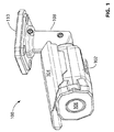
ここで図1及び図2を参照すると、1つの実施形態による、二重通信ポート、装着アーム108、及び取付板110を有する防犯カメラ100の斜視図及び底面図がそれぞれ示されている。装着アーム108及び取付板110は、総称してカメラ「取付組立体」である。カメラ100は、光が進入するのを可能にする開口部106を有するカメラ本体102を含み、その内部に収容される。レンズ(図示せず)は、カメラ本体102に搭載され、開口部106を通ってカメラ本体102に進入する光を屈折するように位置決めされる。図示の実施形態において、レンズはカメラ本体102内に収容されているが、代替的な実施形態(図示せず)において、レンズをカメラ本体102の外側に搭載することができる。カメラ本体102の前方に張り出したフード104が、カメラ本体102の左側及び右側に取付けられ、カメラ本体102の上部に沿って延びている。カメラ本体102の後部には、装着アーム108が取付けられており、装着アーム108はカメラ本体102を装着面に固定される取付板110に連結する。
Referring now to FIGS. 1 and 2, there are shown a perspective view and a bottom view, respectively, of a
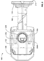
カメラ本体102の底面には構成用パネル202があり、その上には、以下に詳細に説明する、構成用イーサネット(Ethernet)ポート204bの形態の二次通信ポートと、接続状態LED206と、リンクLED208とを有する。取付板110上には、カメラ100を識別するシリアル番号タグ210と、カメラ100が装着された場合に装着面に隣接する取付板110の表面上のアクセスポート(図示せず)とがある。一次イーサネットポート204a(図3に示す)の形態の一次通信ポートは、このアクセスポートを通じてアクセス可能であり、カメラ設置中にネットワークに接続される。イーサネットポート204aは、カメラ本体102が装着された場合、装着面の片側(例えば壁の裏側)にあり、他方、構成用イーサネットポート204b及びレンズは、カメラ本体102が装着された場合、装着面の反対側(例えば壁の前側)にある。構成用イーサネットポート204bは、その結果として、カメラ100が装着面に装着された後でも技術者が容易にアクセス可能であり、他方、アクセスポートはそうではない。
On the bottom surface of the
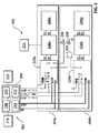
図3を参照すると、カメラ本体102に収容されたイメージャ318、制御及び処理回路302、並びに通信回路304a、304bのブロック図300が示される。イメージャ318は、レンズによって屈折された光を受けて制御及び処理回路302に信号を出力するように位置決めされ、制御及び処理回路は、図3においては、システム・オン・チップ(SoC)308、並びにSoC308に実行させるためのステートメント及び命令を格納する不揮発性メモリなどのコンピュータ可読媒体320である。例示的なステートメント及び命令は、図4に示すような、以下に詳細に説明する、カメラ100のポート204a、b間を切り換えるための方法400を含む。SoC308は、プロセッサ310を含み、これは、SoC308のその他の構成要素である、画像信号プロセッサ(ISP)316、媒体アクセスコントローラ(MAC)314、及び汎用入力/出力(GPIO)ライン312の形態の入力/出力制御回路の各々と通信可能に結合する。プロセッサ310は、コンピュータ可読媒体320とも通信可能に結合する。
Referring to FIG. 3, a block diagram 300 of an
2つのバス、すなわち媒体非依存インタフェース(media independent interface)(MII)バス及び管理データ入力/出力インタフェース(MDIO)バスがMAC314に接続される。これら2つのバスは、MAC314により、一次及び二次通信回路304a、304bと通信するために用いられ、一次及び二次通信回路304a、304bにより共有される。一次通信回路304aは、一次イーサネット物理層(IC)(イーサネット物理層ICを以後「PHY」と称する)324aを含み、これは送信及び受信ラインを用いて、イーサネット・マグネティクス326aを介して一次イーサネットポート204aに通信可能に結合する。イーサネット・マグネティクス326aには、カメラが一次イーサネットポート204aを介してネットワークに接続された場合にネットワークから電力を受け取るDC/DC変換器322が電気的に結合され、この電力は、パワー・オーバー・イーサネット(PoE)技術を用いてカメラ100に給電するために用いられる。一次PHY324aは、MDIO及びMIIバスを介してMAC314に接続される。同様に、二次通信回路304bは、送信及び受信ラインを用いてイーサネット・マグネティクス326bを介して構成用イーサネットポート204bに通信可能に結合する、二次PHY324bを含む。二次PHY324bもまた、MDIO及びMIIバスを介してMAC314に接続される。図示の実施形態において、イーサネットポート204a、bの各々は、RJ−45コネクタであり、PHY324a、bの各々は、Broadcom(商標)BCM5421 10/100BaseT(高速)イーサネット物理層ICである。
Two buses are connected to the MAC 314: a media independent interface (MII) bus and a management data input / output interface (MDIO) bus. These two buses are used by the
GPIOライン312のうち図3でRESET_PHY1と表示された1つは、一次PHY324a上のリセットピンに接続され、一方、図3でRESET_PHY2と表示された別のGPIOライン312は、二次PHY324b上のリセットピンに接続される。従って、SoC308は、PHY324a、bの各々を独立にリセットすることができる。図3でPHY_ADDRESSと表示された別のGPIOライン312は、PHY324a、bの各々のMDIOアドレス選択ピンに接続される。PHY324a、bの特定の1つに対するリセット信号をディアサートする一方でPHY_ADDRESSを制御することにより、SoC308は、別々のMDIOアドレスをPHY324a、bの各々に割り当てることができ、これは、PHY324a、bの両方が共有MDIOバス上で通信することを可能にするために行われる。この手順は、システム初期化中に行われる。
One of the
また、PHY324a、bの各々は、高ストラップされた(strapped high)ピンである隔離(isolate)ピンを有する。その結果として、PHY324a、bは、PHY324a、bの各々がイーサネットポート204a、bから受け取るいかなる入力も無視する「超隔離(super isolated)」モードで起動し、MIIバスに接続されたそれらの出力は、高インピーダンス状態に設定される。SoC308は、MDIOバスを用いて、PHY324a、bを「隔離」モードに移行するように構成することができ、この場合、PHY324a、bは、ポート204a、bがアクティブリンクに結合しているか否かを検出することができるが、そのMIIに接続された出力はいまだ高インピーダンス状態に設定されており、また、隔離モードを出てアクティブモードに入るように構成することができ、その場合、PHY324a、bはMIIバス上でデータを伝送することが可能になる。イーサネットが通信に用いられる図示の実施形態において、「アクティブリンクに結合している」とは、PHY324a、bがポート204a、bを介してアクティブなイーサネット接続に結合していることを意味する。より一般的には、「アクティブリンクに結合している」とは、一次及び二次通信回路がそれぞれ一次及び二次通信ポートを介して、その一次及び二次通信回路が使用するように設計されているプロトコルを用いて通信するアクティブ接続に結合していることを意味する。
Also, each of the
PHY324a、bの各々は、「リンク(link)」ピンを有し、これは、PHY324a、bがアクティブリンクを検出しない場合には低レベルになり、検出した場合には高レベルになる。PHY324a、bからのリンクピンを合わせて論理和(OR)を取り、その結果をリンクLED208に出力する。従って、リンクLED208は、PHY324a、bのいずれかがアクティブリンクに結合しているか否かを示す。一次PHY324aはまた、SoC308がMDIOバスを介して制御する「状態(status)」ピンも有する。状態ピンは、状態LED206に接続し、従って、状態LED206は、SoC308によって判定された状態を示す。
Each of the
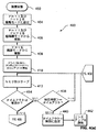
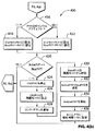
ここで図4(a)及び図4(b)を参照すると、カメラ100の二重通信ポート204a、b間を切り換えるための方法400のフローチャートが示されている。SoC308は、構成用イーサネットポート204bを監視して、これがアクティブリンクに結合された場合を検出する。これがアクティブリンクに結合された場合、例えば、技術者が設置中にカメラ100の焦点及び照準を合わせるために映像端末を接続した場合、SoC308は、イメージャ318上に入射した光から得られるデジタル映像情報を含むデジタル通信信号を、構成用イーサネットポート204bに送信する。SoC308がその前にデジタル通信信号を一次イーサネットポート204aに送信していた場合、図示の実施形態において、SoC308は、信号を構成用イーサネットポート204bに送信する前に一次イーサネットポート204aへのデジタル通信信号の送信を中止する。図4(a)及び図4(b)において、一次PHY324aはPHY1と称され、二次PHY324bはPHY2と称される。
Referring now to FIGS. 4 (a) and 4 (b), a flowchart of a
ブロック402において、カメラ100が起動する。上述のように、PHY324a、bは、超隔離モードで起動するようにピン・ストラップされる。ブロック404において、SoC308は、MDIOバス上でコマンドを送出することによりPHY324a、bの両方を隔離モードに設定する。ブロック406において、SoC308は、PHY324a、bの両方を超隔離モードから解除する。図示の実施形態において、PHY324a、bは超隔離モードで起動するが、代替的な実施形態(図示せず)では、PHY324a、bは、隔離モードで起動するものとすることができる。SoC308は次に、ブロック408において一次PHY324aを隔離モードから解除し、これは一次PHY324aをアクティブモードに設定することと同等である。SoC308は次に、ブロック410において、ドライバを初期化し、SoC308がPHY324a、bのうちのどちらが現在アクティブモードにあるかを記憶するために用いる変数ActivePHYを、一次PHY324aに設定する。SoC308はまた、変数タイムアウトを初期化して、無効にする。以下により詳細に説明するように、タイムアウト変数を用いて、物理層からアプリケーション層にいつメッセージを送るかを決定する。ブロック404から410までは、方法400の初期化フェーズを表す。
In
ブロック412において、SoC308は、Nmsの間、スリープし、これは図示の実施形態では500msである。ブロック414において、SoC308は、タイムアウトが有効であるか否か判定する。SoC308が最初に方法400を実行する際にタイムアウトは無効であり、SoC308は、構成用イーサネットポート204bがアクティブリンクに結合しているか否かを判定するブロック416に進み、それは、SoC308がMDIOバスを介して監視することができる。「いいえ」であれば、SoC308は、技術者がまだ構成用イーサネットポート204bに映像端末を接続していないと判断し、SoC308はブロック418に進み、ここで、変数OldPHYを、二次PHY324bを表すように設定し、変数NewPHYを、一次PHY324aを表すように設定する。SoC308は次にブロック420に進み、ここで、NewPHYで表されるPHY324a、bがActivePHYであるか否かを判定する。この場合、NewPHY及びActivePHYは両方とも一次PHY324aなので、答えは「はい」であり、SoC308は、ブロック412に戻り、技術者が構成用イーサネットポート204bをアクティブリンクに結合するまで、ブロック412から420を通ってループする。
At
ひとたび技術者が、例えば構成用イーサネットポート204bをイーサネットケーブルを介してカメラ100とインタフェースするために用いられるソフトウェアを有するラップトップと接続することによって、構成用イーサネットポート204bをアクティブリンクに結合すると、二次PHY324bは、アクティブリンクを検出し、これをMDIOバスを介してSoC308に報告する。SoC308は、次回、ブロック416に達すると、アクティブリンクを検出してブロック422に進み、ここでOldPHYが一次PHY324aに設定され、NewPHYが二次PHY324bに設定される。ブロック420において、SoC308は、ActivePHYがNewPHYでないと判定し、その結果、ブロック424に進み、ここでOldPHY(一次PHY324a)を停止し、これをMDIOバスを介して隔離モードに設定する(ブロック426)。SoC308は、ブロック428において、イーサネットリンクがダウンしたことをアプリケーション層に通知する。従って、カメラ100上で実行されているアプリケーションソフトウェアは、イーサネット接続が失われたと信じ、従って、物理層が一次PHY324aから二次PHY324bに移行したものとして反応することができる。ブロック430において、SoC308は、NewPHY(二次PHY324b)を隔離モードから解除し、次いでActivePHYを、二次PHY324bを表すように設定し(ブロック432)、次いで二次PHY324bを用いることを開始する(ブロック434)。SoC308は次にブロック436に進み、ここでタイムアウトを現在時間(current time)+Mの有効値に設定し、図示の実施形態において、Mは2,000msである。タイムアウトを設定した後、SoC308はブロック412に戻る。
Once the engineer couples the
N=500ms、M=2,000msである、図示の実施形態において、SoC308は、ブロック412、414及び438を通って3回ループし、4回目にSoC308は、ブロック438において現在時間がタイムアウトと等しいと判定してブロック440に進み、ここで、ブロック412に直接戻る代わりに、タイムアウトをリセットして無効にする。ブロック440の後、SoC308はブロック442に進み、ここでアクティブリンクが復帰したことをアプリケーション層に通知し、次いでブロック412に進む。これは、物理層を、アプリケーション層に対して、アクティブリンクが2,000msの間失われていた後で復帰したかのように有効にシミュレートさせるものであり、それにより、アプリケーション層は、一次PHY324aのみの使用に合わせて設計されたレガシープログラミングを用いて、一次PHY324aから二次PHY324bへの移行をおこなうことが可能になる。アプリケーション層は、二重ポート204a、bを知ることなく、及び、1つのポートのアクティブリンクの喪失及び復帰として認識したものが実際には一次PHY324aから二次PHY324bへの移行であることを知ることなく、機能することができる。しかしながら、代替的な実施形態(図示せず)では、アプリケーション層は、カメラ100が2つのポート204a、bを有すること知った上でプログラムすることができ、上述のように喪失リンクをシミュレートする物理層なしで、2つのポート204a、b間の移行をおこなうことができる。
In the illustrated embodiment where N = 500 ms and M = 2,000 ms, the
ブロック412に戻った後、SoC308は、技術者がアクティブリンクを構成用イーサネットポート204bから除去するまで、例えばイーサネットケーブルを構成用イーサネットポート324bから抜くまで、ブロック412と420との間でループする。
After returning to block 412, the
アクティブリンクが除去された後、二次PHY324bは、アクティブリンクの停止を検出し、これをMDIOバスを介してSoC308に報告する。SoC308は、次回ブロック416に達すると、アクティブリンクが存在しないことを検出し、ブロック418に進み、ここでOldPHYが二次PHY324bに設定され、NewPHYが一次PHY324aに設定される。ブロック420において、SoC308は、ActivePHYがNewPHYではないと判定し、その結果、ブロック424に進み、ここでOldPHY(二次PHY324b)を停止し、これを隔離モードに設定する(ブロック426)。SoC308は、ブロック428において、イーサネットリンクがダウンしたことをアプリケーション層に通知する。従って、カメラ100上で実行されているアプリケーションソフトウェアは、イーサネット接続が再び失われたと信じ、従って、物理層が二次PHY324bから一次PHY324aに移行したものとして反応することができる。ブロック430において、SoC308は、NewPHY(一次PHY324a)を隔離モードから解除し、次いでActivePHYを、一次PHY324aを表すように設定し(ブロック432)、次いで一次PHY324aを用いることを開始する(ブロック434)。SoC308は次にブロック436に進み、ここでタイムアウトを現在時間+Mの有効値に設定し、図示の実施形態において、Mは2,000msである。タイムアウトを設定した後、SoC308はブロック412に戻り、そこでSoC308は、アクティブリンクが復帰したことをアプリケーション層に通知する前に、2,000msにわたって、待機することになる。SoC308は次に、ブロック412に戻り、構成用イーサネットポート204bが再び使用されるまでブロック412と420との間でループする。
After the active link is removed, the
上記実施形態においては、一次イーサネットポート204aは、構成用イーサネットポート204bがアクティブリンクに結合される前、その間、及びその後にアクティブリンクに結合されているが、代替的な実施形態では、これは必ずしも当てはまらない。例えば、技術者は、一次イーサネットポート204aをネットワークに接続する前に構成用イーサネットポート204bを用いることができ、又は構成用イーサネットポート204bが使用されている間、ネットワークをオフラインにすることができる。
In the above embodiment, the
さらに、上記実施形態では、PHY324a、bは、MII及びMDIOバスを共有し、それにより同じMAC314に結合している。しかしながら、代替的な実施形態では、これは必ずしも当てはまらない。例えば、図5(a)に示すこれら代替的実施形態のうちの1つでは、制御及び処理回路302は、図3に示すものと同様であるが、付加的なプロセッサ310’と、プロセッサ310’に通信可能に結合する付加的なMAC314’と、プロセッサ310'に通信可能に結合する付加的なコンピュータ可読媒体320’とをさらに含む。付加的なプロセッサ310'は、図3に示すプロセッサ310に接続される。通信回路34a、bがMAC314を共有する代わりに、一次PHY324a(図5(a)には明示されていないが、一次通信回路304aの一部)は、MAC314の一方のMII及びMDIOバスに結合し、一方、二次PHY324b(図5(a)には明示されていないが、二次通信回路304bの一部)は、他方のMAC314’のMII及びMDIOバスに結合される。PHY324a、bは、プロセッサ310、310’によって個別にリセットされるのとは対照的に、システム全体のリセットに関連してリセットされる。PHY324a、bがMDIOもMIIバスも共有しないので、PHY324a、bのアドレスピンは使用されない。図3の場合と同様に、イメージャ318は、プロセッサ310の一方と通信するISP316に接続され、DC/DC変換器322は、一次通信回路304aに接続され、カメラ100に給電する。2つのプロセッサ310、310’は互いに通信して、所与の時間にデジタル通信信号をポート204a、bの一方又は両方に送信する。
Further, in the above embodiment,
もう一つのこれら代替的な実施形態において、制御及び処理回路302は、2つのMAC314、314’を有しているが、それらはSoC308に組み込まれているか、又はSoC308の一部でなくても同じプロセッサ310によって制御されるか、そのいずれかである。図5(b)は、2つのMAC314、314’がSoC308に統合された実施形態を示し、制御及び処理回路302は、それ以外は図3に示すものと同様である。図5(a)の実施形態の場合と同様に、PHY324aの各々が、MAC314、314'の一方に、そのMAC314、314'のMDIO及びMIIバスを介して接続される。PHY324a、bは、GPIOライン312によって個別にリセットされるのとは対照的に、システム全体のリセットに関連してリセットされる。これもまた図5(a)の場合と同様に、PHY324a、bの各々が独自のMAC314、314'に接続されているので、PHY324a、bのアドレスピンは未使用のまま残される。図3及び図5(a)の場合と同様に、DC/DC変換器322が一次通信回路304aに接続され、カメラ100に給電する。
In another of these alternative embodiments, the control and
図5(c)に示されるもう一つのこれら代替的な実施形態において、制御及び処理回路302は、MAC314とPHY324a、bとの間に挿入されたハブ502又はスイッチ503を含む。さらに、PHY324a、bは、GPIOライン312によって個別にリセットされるのとは対照的に、システム全体のリセットに関連してリセットされる。制御及び処理回路302は、PHY324a、bは、ハブ502又はスイッチ503を介して同じMAC314に接続され、それ以外は図3に示すものと同一である。ハブ502が用いられる場合、ハブ502は、MAC314からPHY324a、bに送信される全てのパケットを複製するので、PHY324a、bの各々が、SoC308から同じデジタル通信信号を受信する。ハブ502は、PHY324a、bのどちらかからMAC314に送られた全てのパケットを同じように直列化する。ハブ502は、例えばFPGAを用いて、又は集積回路として実装することができる。MAC314からPHY324a、bに送信される全てのパケットを複製する代わりに、スイッチ503が用いられる場合、MAC314から一次イーサネットポート204a宛のパケットは一次PHY324aのみに伝送され、二次イーサネットポート204b宛のパケットは二次PHY324bのみに伝送される。スイッチ503又はハブ502を組み入れた代替的な実施形態では、SoC308がスイッチ又はハブと常に通信状態にあるので、SoC308は、リンクのアップ又はダウンをアプリケーションに通知しない(ブロック442及び428)。図3、図5(a)及び図5(b)の場合と同様に、DC/DC変換器322が一次通信回路304aに接続され、カメラ100に給電する。
In another of these alternative embodiments shown in FIG. 5 (c), the control and
また、前述の実施形態において、SoC308は、構成用イーサネットポート204bがアクティブリンクに結合しているか否かを検出し、デジタル通信信号を、構成用イーサネットポート204bのみに、構成用イーサネットポート204bがアクティブリンクに結合した場合にのみ送信する。代替的な実施形態(図示せず)では、これは必ずしも当てはまらない。例えば、SoC308は、ハブを用いる上記の実施形態で説明したように、デジタル通信信号を両方のポート204a、bに同時に、常に送ることができ、又は構成用イーサネットポート204bがアクティブリンクに結合している場合にのみ送ることができる。あるいは、SoC308は、構成用イーサネットポート204bがアクティブリンクに結合しているか否かにかかわらず、デジタル通信信号を常に構成用イーサネットポート204bに送信することができる。あるいは、図示した実施形態及びスイッチを組み入れた上述の代替的な実施形態において、デジタル通信信号を、一次イーサネットポート204a又は構成用イーサネットポート204bに別々に送信することができる。
In the above-described embodiment, the
さらに、前述の実施形態においてカメラ100は弾丸型カメラとして示されているが、代替的な実施形態(図示せず)において、ドーム型カメラなど異なる型式のカメラを用いることができる。
Furthermore, although the
前述の実施形態ではSoCが用いられているが、代替的な実施形態(図示せず)において、SoCは、代わりに、例えば、マイクロプロセッサ、マイクロコントローラ、プログラム可能論理コントローラ、フィールドプログラム可能ゲートアレイ、又は特定用途向け集積回路とすることができる。コンピュータ可読媒体の例は、非一時的なものであり、CD−ROM及びDVDなどのディスクベースの媒体、ハードドライブ及びその他の形態の磁気ディスクストレージなどの磁気媒体、並びにフラッシュメディア、ランダムアクセスメモリ、及び読出し専用メモリなどの半導体ベースの媒体を含む。 Although the SoC is used in the previous embodiments, in alternative embodiments (not shown), the SoC can instead be replaced by, for example, a microprocessor, a microcontroller, a programmable logic controller, a field programmable gate array, Or it can be an application specific integrated circuit. Examples of computer readable media are non-transitory, such as disk-based media such as CD-ROM and DVD, magnetic media such as hard drives and other forms of magnetic disk storage, and flash media, random access memory, And semiconductor based media such as read only memory.
本明細書で論じたいずれの態様及び実施形態のいずれの部分も、本明細書で論じたその他のいずれの態様又は実施形態のいずれの部分と共に実装すること又は組み合わせることができることが意図されている。 It is contemplated that any part of any aspect and embodiment discussed herein may be implemented or combined with any part of any other aspect or embodiment discussed herein. .
便宜上、上記の例示的な実施形態は、相互接続した種々の機能ブロックとして説明される。しかしながら、これは必ずしも必須ではなく、これらの機能ブロックを、均等に集約して、明確な境界を持たない単一の論理装置、プログラム又は動作にする場合があり得る。いずれにしても、機能ブロックは、それ自体で、又はハードウェア若しくはソフトウェアのその他の部分との組み合わせで、実装することができる。 For convenience, the above exemplary embodiments are described as various functional blocks interconnected. However, this is not absolutely necessary, and these functional blocks may be evenly aggregated into a single logic device, program or operation that does not have a clear boundary. In any case, the functional blocks can be implemented by themselves or in combination with other parts of hardware or software.
図4(a)及び(b)は、例示的な方法の実施形態のフローチャートを示す。フローチャート内に示されたブロックのうちの幾つかは、記載された順序とは異なる順序で実行することができる。また、フローチャート内に記載されたブロックの全てを実行する必要があるわけではないこと、付加的なブロックを追加することができること、及び図示したブロックの幾つかをその他のブロックで置き換えることができることを認識されたい。 4 (a) and 4 (b) show a flowchart of an exemplary method embodiment. Some of the blocks shown in the flowchart may be executed in an order different from the order described. Also, not all of the blocks listed in the flowchart need to be executed, additional blocks can be added, and some of the blocks shown can be replaced with other blocks. I want to be recognized.
特定の実施形態を上述したが、その他の実施形態が可能であり、本明細書に含まれることが意図されることを理解されたい。前述の実施形態に対する、図示していない変形形態及び修正形態が可能であることが、当業者には明らかである。 While specific embodiments have been described above, it is to be understood that other embodiments are possible and are intended to be included herein. It will be apparent to those skilled in the art that variations and modifications not shown may be made to the foregoing embodiments.
100:カメラ
102:カメラ本体
104:フード
106:開口部
108:装着アーム
110:取付板
202:構成用パネル
204a:一次イーサネットポート
204b:二次イーサネットポート(構成用イーサネットポート)
206:接続状態LED
208:リンクLED
210:シリアル番号タブ
300:ブロック図
302:制御及び処理回路
304a:一次通信回路
304b:二次通信回路
308:システム・オン・チップ
310:プロセッサ
312:汎用入力/出力(GPIO)ライン
314:媒体アクセスコントローラ(MAC)
318:イメージャ
320:コンピュータ可読媒体
322:DC/DC変換器
324a:一次イーサネット物理層(一次PHY)
324b:二次イーサネット物理層(二次PHY)
326a、b:イーサネット・マグネティクス
100: camera 102: camera body 104: hood 106: opening 108: mounting arm 110: mounting plate 202:
206: Connection status LED
208: Link LED
210: Serial number tab 300: Block diagram 302: Control and
318: Imager 320: Computer readable medium 322: DC /
324b: Secondary Ethernet physical layer (secondary PHY)
326a, b: Ethernet Magnetics
Claims (60)
(a)光がカメラ本体に進入するのを可能にする開口部を含む、装着面に装着可能なカメラ本体と、
(b)前記カメラ本体に搭載され、前記開口部を通って前記カメラ本体に進入する光を屈折させるように位置決めされたレンズと、
(c)前記カメラ本体内に配置され、前記レンズによって屈折された光を受けるように位置決めされたイメージャと、
(d)前記カメラ本体の外部からアクセス可能な一次通信ポートを含み、前記一次通信ポートが、前記カメラ本体が装着された場合に前記装着面の片側に配置される、一次通信回路と、
(e)前記カメラ本体の外部からアクセス可能な二次通信ポートを含み、前記二次通信ポート及び前記開口部が、前記カメラ本体が装着された場合に前記装着面の反対側に配置される、二次通信回路と、
(f)前記イメージャ並びに前記一次及び二次通信回路に通信可能に結合する制御及び処理回路であって、プロセッサと、前記プロセッサに通信可能に結合し、前記二次通信ポートがアクティブリンクに結合している場合に、前記プロセッサに、前記イメージャ上に入射した光から得られるデジタル通信信号を前記二次通信ポートに送信させる、コード化されたステートメント及び命令を有するコンピュータ可読媒体とを含む、制御及び処理回路と、
を含むことを特徴とする、防犯カメラ。 A security camera having a dual communication port,
(A) a camera body attachable to a mounting surface, including an opening that allows light to enter the camera body;
(B) a lens mounted on the camera body and positioned to refract light that enters the camera body through the opening;
(C) an imager disposed within the camera body and positioned to receive light refracted by the lens;
(D) a primary communication circuit including a primary communication port accessible from the outside of the camera body, wherein the primary communication port is disposed on one side of the mounting surface when the camera body is mounted;
(E) including a secondary communication port accessible from the outside of the camera body, wherein the secondary communication port and the opening are disposed on the opposite side of the mounting surface when the camera body is mounted; A secondary communication circuit;
(F) a control and processing circuit communicatively coupled to the imager and the primary and secondary communication circuits, wherein the processor and the processor are communicatively coupled, and the secondary communication port is coupled to an active link. And a computer readable medium having coded statements and instructions for causing the processor to transmit a digital communication signal derived from light incident on the imager to the secondary communication port. A processing circuit;
A security camera characterized by including:
(a)前記一次PHYを停止させ、
(b)前記二次PHYを作動させる前にアクティブリンクが存在しないことをアプリケーション層に通知させ、
(c)前記MIIバスに接続した前記一次PHYの出力を高インピーダンス状態に設定させ、
(d)前記MIIバスに接続した前記二次PHYの出力を高インピーダンス状態から解除し、
(e)前記二次PHYを作動させ、及び
(f)前記アクティブリンクが存在することを前記アプリケーション層に通知させる、
ことを特徴とする、請求項11に記載の防犯カメラ。 The statements and instructions further cause the processor to transmit the digital communication signal through the primary PHY to the primary communication port before detecting that the secondary communication port is coupled to the active link. And after setting the output of the secondary PHY connected to the MII bus to a high impedance state and detecting that the secondary communication port is coupled to the active link,
(A) stopping the primary PHY;
(B) inform the application layer that there is no active link before activating the secondary PHY;
(C) setting the output of the primary PHY connected to the MII bus to a high impedance state;
(D) canceling the output of the secondary PHY connected to the MII bus from a high impedance state;
(E) activating the secondary PHY, and (f) notifying the application layer that the active link exists,
The security camera according to claim 11, characterized in that:
(a)前記二次通信ポートが前記アクティブリンクに結合していることを検出する前に、前記一次通信ポートに前記一次PHYを介して前記デジタル通信信号を送信するステップ、及び、前記MIIバスに接続した前記二次PHYの出力を高インピーダンス状態に設定するステップ、並びに
(b)前記二次通信ポートが前記アクティブリンクに結合していることを検出した後に、
(i)前記一次PHYを停止するステップ、
(ii)前記二次PHYを作動させる前にアクティブリンクが存在しないことをアプリケーション層に通知するステップ、
(iii)前記MIIバスに接続した前記一次PHYの出力を高インピーダンス状態に設定するステップ、
(iv)前記MIIバスに接続した前記二次PHYの出力を高インピーダンス状態から解除するステップ、
(v)前記二次PHYを作動させるステップ、及び
(vi)前記アクティブリンクが存在することを前記アプリケーション層に通知するステップ、
をさらに含むことを特徴とする、請求項19に記載の方法。 The security camera further includes a media independent interface (MII) bus and primary and secondary PHYs, each of which has an output connected to the MII bus, through which the digital communication signal Are transmitted to the primary and secondary communication ports, the method comprising:
(A) transmitting the digital communication signal to the primary communication port via the primary PHY before detecting that the secondary communication port is coupled to the active link; and to the MII bus Setting the output of the connected secondary PHY to a high impedance state, and (b) after detecting that the secondary communication port is coupled to the active link,
(I) stopping the primary PHY;
(Ii) notifying the application layer that no active link exists before activating the secondary PHY;
(Iii) setting the output of the primary PHY connected to the MII bus to a high impedance state;
(Iv) releasing the output of the secondary PHY connected to the MII bus from a high impedance state;
(V) activating the secondary PHY; and (vi) notifying the application layer that the active link exists;
20. The method of claim 19, further comprising:
(a)光がカメラ本体に進入するのを可能にする開口部を含むカメラ本体と、
(b)前記カメラ本体に搭載され、前記開口部を通って前記カメラ本体に進入する光を屈折させるように位置決めされたレンズと、
(c)前記カメラ本体内に配置され、前記レンズによって屈折された光を受けるように位置決めされたイメージャと、
(d)前記カメラ本体に取付けられ、装着面に装着可能な取付組立体と、
(e)前記取付組立体を通してアクセス可能で、前記カメラ本体が前記装着面に装着されるとき前記装着面の片側に一次通信ポートを含む一次通信回路と、
(f)前記カメラ本体を通してアクセス可能で、前記カメラ本体が前記装着面に装着されるとき前記装着面の反対側に二次通信ポートを含む二次通信回路と、
(g)前記イメージャ並びに前記一次及び二次通信回路に通信可能に結合する制御及び処理回路であって、プロセッサと、前記プロセッサに通信可能に結合し、前記二次通信ポートがアクティブリンクに結合している場合に、前記プロセッサに、前記イメージャ上に入射した光から得られるデジタル通信信号を前記二次通信ポートに送信させる、コード化されたステートメント及び命令を有するコンピュータ可読媒体とを含む、制御及び処理回路と、
を含むことを特徴とする、防犯カメラ。 A security camera having a dual communication port,
(A) a camera body including an opening that allows light to enter the camera body;
(B) a lens mounted on the camera body and positioned to refract light that enters the camera body through the opening;
(C) an imager disposed within the camera body and positioned to receive light refracted by the lens;
(D) an attachment assembly attached to the camera body and attachable to the attachment surface;
(E) a primary communication circuit that is accessible through the mounting assembly and includes a primary communication port on one side of the mounting surface when the camera body is mounted on the mounting surface ;
(F) a secondary communication circuit accessible through the camera body and including a secondary communication port on the opposite side of the mounting surface when the camera body is mounted on the mounting surface ;
(G) a control and processing circuit communicatively coupled to the imager and the primary and secondary communication circuits, communicatively coupled to the processor and the processor, wherein the secondary communication port is coupled to an active link; And a computer readable medium having coded statements and instructions for causing the processor to transmit a digital communication signal derived from light incident on the imager to the secondary communication port. A processing circuit;
A security camera characterized by including:
(a)前記一次PHYを停止させ、
(b)前記二次PHYを作動させる前にアクティブリンクが存在しないことをアプリケーション層に通知させ、
(c)前記MIIバスに接続した前記一次PHYの出力を高インピーダンス状態に設定させ、
(d)前記MIIバスに接続した前記二次PHYの出力を高インピーダンス状態から解除し、
(e)前記二次PHYを作動させ、及び
(f)前記アクティブリンクが存在することを前記アプリケーション層に通知させる、
ことを特徴とする、請求項39に記載の防犯カメラ。 The statements and instructions further cause the processor to transmit the digital communication signal through the primary PHY to the primary communication port before detecting that the secondary communication port is coupled to the active link. And after setting the output of the secondary PHY connected to the MII bus to a high impedance state and detecting that the secondary communication port is coupled to the active link,
(A) stopping the primary PHY;
(B) inform the application layer that there is no active link before activating the secondary PHY;
(C) setting the output of the primary PHY connected to the MII bus to a high impedance state;
(D) canceling the output of the secondary PHY connected to the MII bus from a high impedance state;
(E) activating the secondary PHY, and (f) notifying the application layer that the active link exists,
The security camera according to claim 39 , wherein
(a)光が前記カメラ本体に進入するのを可能にする開口部を含む、装着面に装着可能なカメラ本体と、(A) a camera body mountable on a mounting surface, including an opening that allows light to enter the camera body;
(b)前記カメラ本体に搭載され、前記開口部を通って前記カメラ本体に進入する光を屈折させるように位置決めされたレンズと、(B) a lens mounted on the camera body and positioned to refract light that enters the camera body through the opening;
(c)前記カメラ本体内に配置され、前記レンズによって屈折された光を受けるように位置決めされたイメージャと、(C) an imager disposed within the camera body and positioned to receive light refracted by the lens;
(d)前記カメラ本体の外部からアクセス可能な一次通信ポートを含み、前記一次通信ポートが、前記カメラ本体が装着された場合に前記装着面の裏側に配置される一次通信回路と、(D) a primary communication port that is accessible from the outside of the camera body, and the primary communication port is disposed on the back side of the mounting surface when the camera body is mounted;
(e)前記カメラ本体の外部からアクセス可能な二次通信ポートを含み、前記二次通信ポートが、前記カメラ本体が装着された場合に前記装着面の前側に配置される、二次通信回路と、(E) a secondary communication circuit including a secondary communication port accessible from the outside of the camera body, the secondary communication port being disposed on the front side of the mounting surface when the camera body is mounted; ,
(f)前記イメージャ並びに前記一次及び二次通信回路に通信可能に結合する制御及び処理回路であって、プロセッサと、前記プロセッサに通信可能に結合し、前記二次通信ポートがアクティブリンクに結合している場合に、前記プロセッサに、前記イメージャ上に入射した光から得られるデジタル通信信号を前記二次通信ポートに送信させる、コード化されたステートメント及び命令を有するコンピュータ可読媒体とを含む、制御及び処理回路と、(F) a control and processing circuit communicatively coupled to the imager and the primary and secondary communication circuits, wherein the processor and the processor are communicatively coupled, and the secondary communication port is coupled to an active link. And a computer readable medium having coded statements and instructions for causing the processor to transmit a digital communication signal derived from light incident on the imager to the secondary communication port. A processing circuit;
を含むことを特徴とする、防犯カメラ。A security camera characterized by including:
(a)前記一次PHYを停止させ、
(b)前記二次PHYを作動させる前にアクティブリンクが存在しないことをアプリケーション層に通知させ、
(c)前記MIIバスに接続した前記一次PHYの出力を高インピーダンス状態に設定させ、
(d)前記MIIバスに接続した前記二次PHYの出力を高インピーダンス状態から解除し、
(e)前記二次PHYを作動させ、及び
(f)前記アクティブリンクが存在することを前記アプリケーション層に通知させる、
ことを特徴とする、請求項54に記載の防犯カメラ。 The statements and instructions further cause the processor to transmit the digital communication signal through the primary PHY to the primary communication port before detecting that the secondary communication port is coupled to the active link. And after setting the output of the secondary PHY connected to the MII bus to a high impedance state and detecting that the secondary communication port is coupled to the active link,
(A) stopping the primary PHY;
(B) inform the application layer that there is no active link before activating the secondary PHY;
(C) setting the output of the primary PHY connected to the MII bus to a high impedance state;
(D) canceling the output of the secondary PHY connected to the MII bus from a high impedance state;
(E) activating the secondary PHY, and (f) notifying the application layer that the active link exists,
The security camera according to claim 54, wherein
Applications Claiming Priority (3)
| Application Number | Priority Date | Filing Date | Title |
|---|---|---|---|
| US201361752896P | 2013-01-15 | 2013-01-15 | |
| US61/752,896 | 2013-01-15 | ||
| PCT/CA2013/050059 WO2014110653A1 (en) | 2013-01-15 | 2013-01-28 | Security camera having dual communication ports |
Publications (3)
| Publication Number | Publication Date |
|---|---|
| JP2016507171A JP2016507171A (en) | 2016-03-07 |
| JP2016507171A5 JP2016507171A5 (en) | 2016-04-14 |
| JP6017705B2 true JP6017705B2 (en) | 2016-11-02 |
Family
ID=51164838
Family Applications (1)
| Application Number | Title | Priority Date | Filing Date |
|---|---|---|---|
| JP2015551937A Active JP6017705B2 (en) | 2013-01-15 | 2013-01-28 | Security camera with dual communication port |
Country Status (15)
| Country | Link |
|---|---|
| US (1) | US9098108B2 (en) |
| EP (1) | EP2946546B1 (en) |
| JP (1) | JP6017705B2 (en) |
| KR (1) | KR101999420B1 (en) |
| CN (2) | CN110177195A (en) |
| AU (1) | AU2013374189B2 (en) |
| BR (1) | BR112015016695A8 (en) |
| CA (1) | CA2896817C (en) |
| HK (1) | HK1216960A1 (en) |
| IL (1) | IL239678B (en) |
| MX (1) | MX351852B (en) |
| NZ (1) | NZ709728A (en) |
| SG (1) | SG11201505510QA (en) |
| WO (1) | WO2014110653A1 (en) |
| ZA (1) | ZA201505780B (en) |
Families Citing this family (19)
| Publication number | Priority date | Publication date | Assignee | Title |
|---|---|---|---|---|
| CN110177195A (en) | 2013-01-15 | 2019-08-27 | 威智伦公司 | Safety camera with dual communication port |
| US10592727B2 (en) * | 2014-07-28 | 2020-03-17 | Centre For Development Of Advanced Computing | Apparatus for automated monitoring of facial images and a process therefor |
| JP1540708S (en) * | 2015-03-09 | 2015-12-28 | ||
| USD775257S1 (en) * | 2015-09-21 | 2016-12-27 | Avigilon Corporation | Shade for a camera |
| JP2019087776A (en) * | 2017-11-01 | 2019-06-06 | 株式会社ザクティ | Stationary camera device |
| KR102046942B1 (en) * | 2018-01-04 | 2019-11-20 | 주식회사 위드아이앤씨 | Apparatus, method and system for controlling surveillance camera network |
| USD892895S1 (en) * | 2018-03-30 | 2020-08-11 | Hangzhou Hikvision Digital Technology Co., Ltd. | Camera |
| USD866637S1 (en) * | 2018-05-29 | 2019-11-12 | Home Tech LLC | Spotlight camera |
| USD923687S1 (en) * | 2018-12-07 | 2021-06-29 | Portable Multimedia Ltd | Camera mount |
| USD923686S1 (en) * | 2018-12-07 | 2021-06-29 | Portable Multimedia Ltd | Camera mount |
| USD923684S1 (en) * | 2018-12-07 | 2021-06-29 | Portable Multimedia Ltd | Camera mount |
| USD923685S1 (en) * | 2018-12-07 | 2021-06-29 | Portable Multimedia Ltd | Camera mount |
| USD900371S1 (en) * | 2018-12-12 | 2020-10-27 | Shenzhen Tollar Security Equipment Co., Ltd. | Combined outdoor light and solar panel |
| US11863468B2 (en) * | 2019-04-19 | 2024-01-02 | Marvell Asia Pte Ltd | Control of ethernet link-partner GPIO using OAM |
| JP1655241S (en) * | 2019-09-30 | 2020-03-16 | ||
| CN114338456B (en) * | 2020-09-25 | 2024-03-22 | 浙江宇视科技有限公司 | Image acquisition equipment state determining method and device, electronic equipment and medium |
| USD983434S1 (en) * | 2021-12-27 | 2023-04-11 | eNet Innotech (Guangzhou) Limited | Solar lamp |
| US11847071B2 (en) | 2021-12-30 | 2023-12-19 | Pure Storage, Inc. | Enabling communication between a single-port device and multiple storage system controllers |
| US11909709B1 (en) * | 2022-10-24 | 2024-02-20 | Flytech Technology Co., Ltd. | Identifying serially-connected power over ethernet (PoE) networked devices |
Family Cites Families (20)
| Publication number | Priority date | Publication date | Assignee | Title |
|---|---|---|---|---|
| US6930709B1 (en) * | 1997-12-04 | 2005-08-16 | Pentax Of America, Inc. | Integrated internet/intranet camera |
| JP2000244781A (en) * | 1999-02-22 | 2000-09-08 | Sony Corp | Dome type video camera device |
| JP2004064253A (en) * | 2002-07-26 | 2004-02-26 | Skd Ooru:Kk | Observation system in vacuum atmosphere |
| KR100731185B1 (en) * | 2005-05-25 | 2007-06-27 | 카시와야마 토요히테 | Wireless and powercordless camera |
| US7880761B2 (en) * | 2005-07-20 | 2011-02-01 | Lab Partners Associates, Inc. | Wireless photographic communication system and method |
| JP2007150790A (en) * | 2005-11-29 | 2007-06-14 | Sony Corp | Monitoring camera |
| US20070236582A1 (en) * | 2006-03-29 | 2007-10-11 | Imaging Solutions Group Of Ny, Inc. | Video camera with multiple independent outputs |
| JP4640267B2 (en) * | 2006-06-13 | 2011-03-02 | パナソニック株式会社 | Wiring equipment and surveillance camera device |
| CN101127673A (en) * | 2006-08-16 | 2008-02-20 | 华为技术有限公司 | Ethernet automatic protection switching method |
| EP2153641B2 (en) * | 2007-04-13 | 2021-10-27 | Ari M. Presler | Digital cinema camera system for recording, editing and visualizing images |
| JP4618291B2 (en) * | 2007-11-30 | 2011-01-26 | ソニー株式会社 | Transmitting apparatus, receiving apparatus, and operation information transmitting method in receiving apparatus |
| JP4900285B2 (en) * | 2008-03-03 | 2012-03-21 | ソニー株式会社 | Imaging device |
| JP2010073002A (en) * | 2008-09-19 | 2010-04-02 | Hoya Corp | Image processor and camera |
| ES2370560T3 (en) * | 2008-11-06 | 2011-12-20 | Axis Ab | ACCOMMODATION FOR ELECTRONIC DEVICE. |
| CN101771598B (en) * | 2008-12-31 | 2012-01-11 | 中国航空工业第一集团公司第六三一研究所 | Communication dispatching method of real-time Ethernet |
| US20100289904A1 (en) | 2009-05-15 | 2010-11-18 | Microsoft Corporation | Video capture device providing multiple resolution video feeds |
| US8241119B2 (en) | 2010-02-10 | 2012-08-14 | Leap Forward Gaming | Candle devices for gaming machines |
| JP5566262B2 (en) * | 2010-11-05 | 2014-08-06 | Toa株式会社 | Surveillance camera |
| JP2013182068A (en) * | 2012-02-29 | 2013-09-12 | Fujifilm Corp | Monitoring camera and adjusting jig |
| CN110177195A (en) | 2013-01-15 | 2019-08-27 | 威智伦公司 | Safety camera with dual communication port |
-
2013
- 2013-01-28 CN CN201910553155.0A patent/CN110177195A/en active Pending
- 2013-01-28 BR BR112015016695A patent/BR112015016695A8/en not_active Application Discontinuation
- 2013-01-28 MX MX2015009158A patent/MX351852B/en active IP Right Grant
- 2013-01-28 CN CN201380070373.XA patent/CN105191279A/en active Pending
- 2013-01-28 AU AU2013374189A patent/AU2013374189B2/en active Active
- 2013-01-28 NZ NZ709728A patent/NZ709728A/en not_active IP Right Cessation
- 2013-01-28 KR KR1020157022188A patent/KR101999420B1/en active IP Right Grant
- 2013-01-28 US US13/752,264 patent/US9098108B2/en active Active
- 2013-01-28 SG SG11201505510QA patent/SG11201505510QA/en unknown
- 2013-01-28 EP EP13872115.4A patent/EP2946546B1/en active Active
- 2013-01-28 JP JP2015551937A patent/JP6017705B2/en active Active
- 2013-01-28 WO PCT/CA2013/050059 patent/WO2014110653A1/en active Application Filing
- 2013-01-28 CA CA2896817A patent/CA2896817C/en active Active
-
2015
- 2015-06-29 IL IL239678A patent/IL239678B/en active IP Right Grant
- 2015-08-12 ZA ZA2015/05780A patent/ZA201505780B/en unknown
-
2016
- 2016-04-22 HK HK16104640.8A patent/HK1216960A1/en unknown
Also Published As
| Publication number | Publication date |
|---|---|
| SG11201505510QA (en) | 2015-08-28 |
| CN110177195A (en) | 2019-08-27 |
| WO2014110653A1 (en) | 2014-07-24 |
| KR101999420B1 (en) | 2019-07-11 |
| AU2013374189A1 (en) | 2015-07-23 |
| EP2946546A4 (en) | 2016-06-22 |
| BR112015016695A2 (en) | 2017-07-11 |
| NZ709728A (en) | 2016-12-23 |
| CA2896817A1 (en) | 2014-07-24 |
| EP2946546B1 (en) | 2018-07-11 |
| CN105191279A (en) | 2015-12-23 |
| IL239678B (en) | 2019-05-30 |
| MX2015009158A (en) | 2016-03-09 |
| MX351852B (en) | 2017-10-31 |
| HK1216960A1 (en) | 2016-12-09 |
| IL239678A0 (en) | 2015-08-31 |
| US20140198208A1 (en) | 2014-07-17 |
| CA2896817C (en) | 2018-12-11 |
| ZA201505780B (en) | 2017-11-29 |
| US9098108B2 (en) | 2015-08-04 |
| EP2946546A1 (en) | 2015-11-25 |
| AU2013374189B2 (en) | 2016-06-02 |
| JP2016507171A (en) | 2016-03-07 |
| BR112015016695A8 (en) | 2019-10-29 |
| KR20150113022A (en) | 2015-10-07 |
Similar Documents
| Publication | Publication Date | Title |
|---|---|---|
| JP6017705B2 (en) | Security camera with dual communication port | |
| US10148746B2 (en) | Multi-host network interface controller with host management | |
| TW201348979A (en) | Serial port switching system, server and serial port switching method using the same | |
| US6587950B1 (en) | Cluster power management technique | |
| US8719484B2 (en) | System and method for using a multipath | |
| TWI471729B (en) | Methods and structure for communicating between a sata host and a sata target device through a sas domain | |
| JP2016507171A5 (en) | ||
| US7653769B2 (en) | Management of devices connected to infiniband ports | |
| JP6550192B2 (en) | Network device | |
| JP2013505177A (en) | Remote access of elevator control systems with multiple subsystems | |
| US9424218B1 (en) | SAS expander with non-blocking virtual phy architecture | |
| TWI659302B (en) | Hdd monitoring system | |
| WO2015131516A1 (en) | Distributed intelligent platform management bus connection method and atca frame | |
| US10771311B2 (en) | Communication of event messages in computing systems | |
| WO2012059066A1 (en) | Method and system for locating fault in serial port | |
| US20150156117A1 (en) | High density server system | |
| US20080144614A1 (en) | Method and Apparatus to Manage Multiple Infiniband Links in a Mixed Environment with Switches and Proprietary Devices | |
| TW201504806A (en) | Computer host and network communication setting method thereof | |
| US20040267991A1 (en) | Transparent switch | |
| US8787365B2 (en) | Method for managing a switch chip port, main control board, switch board, and system | |
| US8891405B2 (en) | Integrated device management over Ethernet network | |
| TWI485566B (en) | A server equipped with an interface for connecting to a server system and a server system | |
| CN112367280A (en) | RCPU agent board health detection method and RCPU agent board | |
| CN117891773A (en) | Communication control device and method for integrated circuit bus | |
| EP3028159A1 (en) | Configuring a communication interconnect for electronic devices |
Legal Events
| Date | Code | Title | Description |
|---|---|---|---|
| A521 | Request for written amendment filed |
Free format text: JAPANESE INTERMEDIATE CODE: A523 Effective date: 20160121 |
|
| A621 | Written request for application examination |
Free format text: JAPANESE INTERMEDIATE CODE: A621 Effective date: 20160121 |
|
| A871 | Explanation of circumstances concerning accelerated examination |
Free format text: JAPANESE INTERMEDIATE CODE: A871 Effective date: 20160121 |
|
| A975 | Report on accelerated examination |
Free format text: JAPANESE INTERMEDIATE CODE: A971005 Effective date: 20160419 |
|
| A131 | Notification of reasons for refusal |
Free format text: JAPANESE INTERMEDIATE CODE: A131 Effective date: 20160425 |
|
| A521 | Request for written amendment filed |
Free format text: JAPANESE INTERMEDIATE CODE: A523 Effective date: 20160722 |
|
| TRDD | Decision of grant or rejection written | ||
| A01 | Written decision to grant a patent or to grant a registration (utility model) |
Free format text: JAPANESE INTERMEDIATE CODE: A01 Effective date: 20160829 |
|
| A61 | First payment of annual fees (during grant procedure) |
Free format text: JAPANESE INTERMEDIATE CODE: A61 Effective date: 20160928 |
|
| R150 | Certificate of patent or registration of utility model |
Ref document number: 6017705 Country of ref document: JP Free format text: JAPANESE INTERMEDIATE CODE: R150 |
|
| R250 | Receipt of annual fees |
Free format text: JAPANESE INTERMEDIATE CODE: R250 |
|
| R250 | Receipt of annual fees |
Free format text: JAPANESE INTERMEDIATE CODE: R250 |
|
| RD02 | Notification of acceptance of power of attorney |
Free format text: JAPANESE INTERMEDIATE CODE: R3D02 |
|
| R250 | Receipt of annual fees |
Free format text: JAPANESE INTERMEDIATE CODE: R250 |
|
| R250 | Receipt of annual fees |
Free format text: JAPANESE INTERMEDIATE CODE: R250 |
|
| S111 | Request for change of ownership or part of ownership |
Free format text: JAPANESE INTERMEDIATE CODE: R313113 |
|
| R350 | Written notification of registration of transfer |
Free format text: JAPANESE INTERMEDIATE CODE: R350 |
|
| RD02 | Notification of acceptance of power of attorney |
Free format text: JAPANESE INTERMEDIATE CODE: R3D02 |
|
| R250 | Receipt of annual fees |
Free format text: JAPANESE INTERMEDIATE CODE: R250 |