JP6017389B2 - Imaging apparatus, electronic viewfinder, display control method, and display control program - Google Patents
Imaging apparatus, electronic viewfinder, display control method, and display control program Download PDFInfo
- Publication number
- JP6017389B2 JP6017389B2 JP2013192015A JP2013192015A JP6017389B2 JP 6017389 B2 JP6017389 B2 JP 6017389B2 JP 2013192015 A JP2013192015 A JP 2013192015A JP 2013192015 A JP2013192015 A JP 2013192015A JP 6017389 B2 JP6017389 B2 JP 6017389B2
- Authority
- JP
- Japan
- Prior art keywords
- white point
- range
- adaptation
- eyepiece
- electronic viewfinder
- Prior art date
- Legal status (The legal status is an assumption and is not a legal conclusion. Google has not performed a legal analysis and makes no representation as to the accuracy of the status listed.)
- Expired - Fee Related
Links
- 238000000034 method Methods 0.000 title claims description 36
- 238000003384 imaging method Methods 0.000 title claims description 32
- 230000006978 adaptation Effects 0.000 claims description 242
- 230000008859 change Effects 0.000 claims description 54
- 238000001514 detection method Methods 0.000 claims description 19
- 238000012545 processing Methods 0.000 description 55
- 238000012986 modification Methods 0.000 description 21
- 230000004048 modification Effects 0.000 description 21
- 230000008569 process Effects 0.000 description 16
- 230000000875 corresponding effect Effects 0.000 description 13
- 238000012790 confirmation Methods 0.000 description 10
- 238000012937 correction Methods 0.000 description 10
- 238000006243 chemical reaction Methods 0.000 description 9
- 238000010586 diagram Methods 0.000 description 9
- 230000006870 function Effects 0.000 description 9
- 239000003086 colorant Substances 0.000 description 7
- 230000001276 controlling effect Effects 0.000 description 6
- 239000004973 liquid crystal related substance Substances 0.000 description 6
- 230000006835 compression Effects 0.000 description 5
- 238000007906 compression Methods 0.000 description 5
- 230000003287 optical effect Effects 0.000 description 5
- 230000003044 adaptive effect Effects 0.000 description 3
- 230000002596 correlated effect Effects 0.000 description 3
- 238000001454 recorded image Methods 0.000 description 3
- 230000003595 spectral effect Effects 0.000 description 3
- 238000013459 approach Methods 0.000 description 2
- 230000008901 benefit Effects 0.000 description 2
- 239000000470 constituent Substances 0.000 description 2
- 230000006837 decompression Effects 0.000 description 2
- 238000011156 evaluation Methods 0.000 description 2
- 230000004907 flux Effects 0.000 description 2
- 230000014759 maintenance of location Effects 0.000 description 2
- 239000000203 mixture Substances 0.000 description 2
- 238000002834 transmittance Methods 0.000 description 2
- 230000005457 Black-body radiation Effects 0.000 description 1
- 241000282412 Homo Species 0.000 description 1
- 230000003321 amplification Effects 0.000 description 1
- 210000004556 brain Anatomy 0.000 description 1
- 239000003990 capacitor Substances 0.000 description 1
- 238000004891 communication Methods 0.000 description 1
- 230000000694 effects Effects 0.000 description 1
- 230000007613 environmental effect Effects 0.000 description 1
- 239000000284 extract Substances 0.000 description 1
- 230000010354 integration Effects 0.000 description 1
- CNQCVBJFEGMYDW-UHFFFAOYSA-N lawrencium atom Chemical compound [Lr] CNQCVBJFEGMYDW-UHFFFAOYSA-N 0.000 description 1
- 239000011159 matrix material Substances 0.000 description 1
- 230000007246 mechanism Effects 0.000 description 1
- 238000003199 nucleic acid amplification method Methods 0.000 description 1
- 238000004091 panning Methods 0.000 description 1
- 230000009467 reduction Effects 0.000 description 1
- 230000011514 reflex Effects 0.000 description 1
- 230000035945 sensitivity Effects 0.000 description 1
- 238000007493 shaping process Methods 0.000 description 1
- 238000001228 spectrum Methods 0.000 description 1
- 230000001360 synchronised effect Effects 0.000 description 1
- 230000002123 temporal effect Effects 0.000 description 1
- 238000012546 transfer Methods 0.000 description 1
Images


Classifications
-
- G—PHYSICS
- G09—EDUCATION; CRYPTOGRAPHY; DISPLAY; ADVERTISING; SEALS
- G09G—ARRANGEMENTS OR CIRCUITS FOR CONTROL OF INDICATING DEVICES USING STATIC MEANS TO PRESENT VARIABLE INFORMATION
- G09G5/00—Control arrangements or circuits for visual indicators common to cathode-ray tube indicators and other visual indicators
- G09G5/02—Control arrangements or circuits for visual indicators common to cathode-ray tube indicators and other visual indicators characterised by the way in which colour is displayed
- G09G5/026—Control of mixing and/or overlay of colours in general
-
- H—ELECTRICITY
- H04—ELECTRIC COMMUNICATION TECHNIQUE
- H04N—PICTORIAL COMMUNICATION, e.g. TELEVISION
- H04N23/00—Cameras or camera modules comprising electronic image sensors; Control thereof
- H04N23/10—Cameras or camera modules comprising electronic image sensors; Control thereof for generating image signals from different wavelengths
- H04N23/11—Cameras or camera modules comprising electronic image sensors; Control thereof for generating image signals from different wavelengths for generating image signals from visible and infrared light wavelengths
-
- H—ELECTRICITY
- H04—ELECTRIC COMMUNICATION TECHNIQUE
- H04N—PICTORIAL COMMUNICATION, e.g. TELEVISION
- H04N23/00—Cameras or camera modules comprising electronic image sensors; Control thereof
- H04N23/60—Control of cameras or camera modules
- H04N23/61—Control of cameras or camera modules based on recognised objects
-
- H—ELECTRICITY
- H04—ELECTRIC COMMUNICATION TECHNIQUE
- H04N—PICTORIAL COMMUNICATION, e.g. TELEVISION
- H04N23/00—Cameras or camera modules comprising electronic image sensors; Control thereof
- H04N23/60—Control of cameras or camera modules
- H04N23/63—Control of cameras or camera modules by using electronic viewfinders
-
- H—ELECTRICITY
- H04—ELECTRIC COMMUNICATION TECHNIQUE
- H04N—PICTORIAL COMMUNICATION, e.g. TELEVISION
- H04N23/00—Cameras or camera modules comprising electronic image sensors; Control thereof
- H04N23/60—Control of cameras or camera modules
- H04N23/66—Remote control of cameras or camera parts, e.g. by remote control devices
- H04N23/663—Remote control of cameras or camera parts, e.g. by remote control devices for controlling interchangeable camera parts based on electronic image sensor signals
-
- H—ELECTRICITY
- H04—ELECTRIC COMMUNICATION TECHNIQUE
- H04N—PICTORIAL COMMUNICATION, e.g. TELEVISION
- H04N23/00—Cameras or camera modules comprising electronic image sensors; Control thereof
- H04N23/70—Circuitry for compensating brightness variation in the scene
- H04N23/75—Circuitry for compensating brightness variation in the scene by influencing optical camera components
-
- H—ELECTRICITY
- H04—ELECTRIC COMMUNICATION TECHNIQUE
- H04N—PICTORIAL COMMUNICATION, e.g. TELEVISION
- H04N23/00—Cameras or camera modules comprising electronic image sensors; Control thereof
- H04N23/80—Camera processing pipelines; Components thereof
- H04N23/84—Camera processing pipelines; Components thereof for processing colour signals
- H04N23/88—Camera processing pipelines; Components thereof for processing colour signals for colour balance, e.g. white-balance circuits or colour temperature control
-
- H—ELECTRICITY
- H04—ELECTRIC COMMUNICATION TECHNIQUE
- H04N—PICTORIAL COMMUNICATION, e.g. TELEVISION
- H04N9/00—Details of colour television systems
- H04N9/64—Circuits for processing colour signals
- H04N9/73—Colour balance circuits, e.g. white balance circuits or colour temperature control
-
- G—PHYSICS
- G09—EDUCATION; CRYPTOGRAPHY; DISPLAY; ADVERTISING; SEALS
- G09G—ARRANGEMENTS OR CIRCUITS FOR CONTROL OF INDICATING DEVICES USING STATIC MEANS TO PRESENT VARIABLE INFORMATION
- G09G2320/00—Control of display operating conditions
- G09G2320/06—Adjustment of display parameters
- G09G2320/0666—Adjustment of display parameters for control of colour parameters, e.g. colour temperature
-
- G—PHYSICS
- G09—EDUCATION; CRYPTOGRAPHY; DISPLAY; ADVERTISING; SEALS
- G09G—ARRANGEMENTS OR CIRCUITS FOR CONTROL OF INDICATING DEVICES USING STATIC MEANS TO PRESENT VARIABLE INFORMATION
- G09G2320/00—Control of display operating conditions
- G09G2320/06—Adjustment of display parameters
- G09G2320/0673—Adjustment of display parameters for control of gamma adjustment, e.g. selecting another gamma curve
-
- G—PHYSICS
- G09—EDUCATION; CRYPTOGRAPHY; DISPLAY; ADVERTISING; SEALS
- G09G—ARRANGEMENTS OR CIRCUITS FOR CONTROL OF INDICATING DEVICES USING STATIC MEANS TO PRESENT VARIABLE INFORMATION
- G09G2340/00—Aspects of display data processing
- G09G2340/06—Colour space transformation
-
- G—PHYSICS
- G09—EDUCATION; CRYPTOGRAPHY; DISPLAY; ADVERTISING; SEALS
- G09G—ARRANGEMENTS OR CIRCUITS FOR CONTROL OF INDICATING DEVICES USING STATIC MEANS TO PRESENT VARIABLE INFORMATION
- G09G2340/00—Aspects of display data processing
- G09G2340/14—Solving problems related to the presentation of information to be displayed
-
- G—PHYSICS
- G09—EDUCATION; CRYPTOGRAPHY; DISPLAY; ADVERTISING; SEALS
- G09G—ARRANGEMENTS OR CIRCUITS FOR CONTROL OF INDICATING DEVICES USING STATIC MEANS TO PRESENT VARIABLE INFORMATION
- G09G2354/00—Aspects of interface with display user
-
- G—PHYSICS
- G09—EDUCATION; CRYPTOGRAPHY; DISPLAY; ADVERTISING; SEALS
- G09G—ARRANGEMENTS OR CIRCUITS FOR CONTROL OF INDICATING DEVICES USING STATIC MEANS TO PRESENT VARIABLE INFORMATION
- G09G2360/00—Aspects of the architecture of display systems
- G09G2360/14—Detecting light within display terminals, e.g. using a single or a plurality of photosensors
- G09G2360/144—Detecting light within display terminals, e.g. using a single or a plurality of photosensors the light being ambient light
-
- H—ELECTRICITY
- H04—ELECTRIC COMMUNICATION TECHNIQUE
- H04N—PICTORIAL COMMUNICATION, e.g. TELEVISION
- H04N2209/00—Details of colour television systems
- H04N2209/04—Picture signal generators
- H04N2209/041—Picture signal generators using solid-state devices
- H04N2209/042—Picture signal generators using solid-state devices having a single pick-up sensor
- H04N2209/047—Picture signal generators using solid-state devices having a single pick-up sensor using multispectral pick-up elements
-
- H—ELECTRICITY
- H04—ELECTRIC COMMUNICATION TECHNIQUE
- H04N—PICTORIAL COMMUNICATION, e.g. TELEVISION
- H04N23/00—Cameras or camera modules comprising electronic image sensors; Control thereof
- H04N23/60—Control of cameras or camera modules
- H04N23/67—Focus control based on electronic image sensor signals
- H04N23/673—Focus control based on electronic image sensor signals based on contrast or high frequency components of image signals, e.g. hill climbing method
Landscapes
- Engineering & Computer Science (AREA)
- Multimedia (AREA)
- Signal Processing (AREA)
- Physics & Mathematics (AREA)
- Computer Hardware Design (AREA)
- General Physics & Mathematics (AREA)
- Theoretical Computer Science (AREA)
- Studio Devices (AREA)
- Viewfinders (AREA)
- Color Television Image Signal Generators (AREA)
- Processing Of Color Television Signals (AREA)
Description
本発明は、電子ビューファインダを有する撮像装置、このような撮像装置における電子ビューファインダ、表示制御方法、および表示制御用プログラムに関する。 The present invention relates to an imaging apparatus having an electronic viewfinder, an electronic viewfinder in such an imaging apparatus, a display control method, and a display control program.
電子ビューファインダ(以下、「EVF」と略記する)を搭載した撮像装置が提供されている。EVF付きの撮像装置が登場した頃のEVFの大きな特徴は、撮影画像が事前に確認できることであった。このため、大まかな画像の明るさや色味が合っていれば、ユーザのニーズを満たすことができていた。 An imaging apparatus equipped with an electronic viewfinder (hereinafter abbreviated as “EVF”) is provided. A major feature of EVF when an imaging device with an EVF appeared was that the captured image could be confirmed in advance. For this reason, if the brightness and color of the rough image match, the user's needs could be satisfied.
しかし、近年、EVFに対する要求が高まりつつあり、EVFでより正確な撮影画像の再現を行うことができ、撮影前にEVF上で様々な画像調整を行った後に撮影ができることや、またどのような環境でも撮影画像の事前確認ができ、ストレスフリーで撮影ができるといったニーズが増えてきた。 However, in recent years, there has been a growing demand for EVF, and it is possible to reproduce a captured image more accurately with EVF, and to perform shooting after performing various image adjustments on EVF before shooting. There is a growing need for pre-confirmed images taken in the environment and for stress-free shooting.
撮影画像をより正確に再現する上で、色は重要な要素である。しかし、色はさまざまな要因を受けて変化する。その一つが、撮影画像を確認する環境である。例えば、プリントした1枚の画像でも、晴天下で見た場合には、白は白く見えるものの、電球下で見た場合には、白が多少赤っぽく色付いて見える。つまり、どういった環境下で見るかによって、同じものであっても実際に人が見て感じる色味が異なる。 Color is an important factor in reproducing a captured image more accurately. However, the color changes due to various factors. One of them is an environment for confirming a captured image. For example, even with a single printed image, white looks white when viewed under fine weather, but white appears slightly reddish when viewed under a light bulb. In other words, depending on the environment in which the image is viewed, the color that people actually see and feel is the same.
色を再現する要素として、人の目の色順応によっても変わってくる。例えば、同じ撮影画像であっても、電球を点灯した暗室入った直後に見た場合の色味と、暗室に入ってから、十分時間が経ってから見た場合の色味とでは異なって見える。このことは、その環境にどれだけ眼が慣れたか、順応したかによって、実際に人が見て感じる色味が異なることを示している。 It depends on the color adaptation of the human eye as an element of color reproduction. For example, even if it is the same photographed image, the color when viewed immediately after entering a dark room with a light bulb turned on differs from the color when viewed after enough time has passed since entering the dark room. . This shows that the color actually seen and felt by humans differs depending on how much the eye has become accustomed to the environment and how it has adapted.
また、色を再現する要素として、上述の要素以外にも、順応する範囲(追従範囲)によっても、色の見え方は異なる。例えば、同じ撮影画像であっても、晴天下で見た場合と、曇天下で見た場合とは、それほど色味の違いを感じないが、電球など比較的色味の強い光源下で見た場合とでは、色味の違いを感じる。これは、画像を確認する環境の違いと同時に、人の目がどの程度の光源範囲まで、白を白と判断するかによって、実際に人が見て感じる色味が異なることを意味している。 Further, in addition to the above-described elements as elements for reproducing colors, the appearance of colors varies depending on the range to be adapted (following range). For example, even if it is the same shot image, it does not feel a difference in color when viewed under clear sky and when viewed under cloudy weather, but it is viewed under a light source with relatively strong color such as a light bulb. I feel a difference in color. This means that at the same time as the environment in which the image is checked, the color that the human eye actually sees depends on how much light source the human eye judges as white as white. .
色順応については、特許文献1に触れられている。この特許文献1には、使用するフィルムのホワイトバランス、もしくはデジタルカメラのホワイトバランス設定が撮影光源とあっていない状態で撮影された場合に起こる撮影画像の色かぶりに対し、その色かぶりの度合いをその場で確認するためのアイデアが開示されている。特許文献1では、撮影環境での色順応を考慮して、撮影光源の光源情報とホワイトバランス設定に基づき、背面液晶に表示する確認用画像データに逆ホワイトバランス処理を施している。また、特許文献2には、ユーザが被写体からEVFを覗いた場合には、ユーザの目を徐々にEVFの表示に慣らすように表示色温度を変化させることが開示されている。
Japanese Patent Application Laid-Open No. 2004-151867 touches on chromatic adaptation. This
前述の特許文献1では、一応色順応に対応しているが、撮影画像の色を背面液晶で確認する場合、撮影環境での色順応を確認用画像データの色に反映するだけでは不十分であり、確認用画像をどのような白色点の設定された背面液晶に表示するかによっても、色は変わってくる。 In Japanese Patent Application Laid-Open No. 2004-228561, chromatic adaptation is supported. However, when the color of a captured image is confirmed on the rear liquid crystal, it is not sufficient to reflect the chromatic adaptation in the photographing environment on the color of the confirmation image data. Yes, the color changes depending on what kind of white point the rear liquid crystal is set to display the confirmation image.
具体的な例を挙げると、仮に撮影光源とホワイトバランス設定が一致しており、撮影画像と一致するように確認用画像が生成された場合、撮影画像の白と確認用画像の白は一致する。しかし、その確認用画像を赤っぽい(色温度の低い白色点の)液晶パネルに表示すれば、確認用画像の白は赤味を帯びて表示されることなる。また、確認用画像を青っぽい(色温度の高い白色点の)液晶パネルに表示すれば、確認用画像の白は青味を帯びて表示されることになる。したがって、特許文献1に開示の技術では、現状のEVFの課題に対して十分な解決策とはなり得ていない。
To give a specific example, if the photographing light source and the white balance setting match, and the confirmation image is generated so as to coincide with the photographed image, the white of the photographed image matches the white of the confirmation image. . However, if the confirmation image is displayed on a reddish (white point with a low color temperature) liquid crystal panel, the white of the confirmation image is displayed in red. Also, if the confirmation image is displayed on a bluish (white point with a high color temperature) liquid crystal panel, the white of the confirmation image is displayed with a bluish tint. Therefore, the technique disclosed in
また、上述したように色味の感じ方の違いは、EVFで撮影画像の色を再現する上でも大きな影響を与える。しかしながら、現状のEVFはその点まで考慮されておらず、その結果、特定の確認環境下では、撮影画像に比較的近い色が再現できるものの、環境によって、全体的に青っぽく感じたり、赤っぽく感じたりする場合がある。このことが、撮影者を混乱させ、撮影者のイメージを損なわせ、気持ちよく撮影する足かせとなっている。したがって、従来のEVFでは、環境によらない正確な撮影画像の再現ができず、またEVFを覗きながら様々な画像調整を行い撮影するといった事を正確に行なう事はできなかった。 In addition, as described above, the difference in how the user feels the color has a great effect on reproducing the color of the captured image with the EVF. However, the current EVF is not considered to that point, and as a result, a color that is relatively close to the captured image can be reproduced under a specific confirmation environment. However, depending on the environment, the overall EVF feels bluish or reddish. You may feel it. This confuses the photographer, detracts from the photographer's image, and is a drag that shoots comfortably. Therefore, with the conventional EVF, it is impossible to accurately reproduce the captured image regardless of the environment, and it is not possible to accurately perform various image adjustments while looking into the EVF.
この問題点は、前述の特許文献2のように、徐々に表示色温度を変化させることにより、ある程度、解消することができる。しかし、人間の目はある程度までしか環境の色温度に順応することができないので、その色順応範囲を考慮せずに、表示色温度を変化させることは好ましくはない。 This problem can be solved to some extent by gradually changing the display color temperature as in Patent Document 2 described above. However, since the human eye can only adapt to the environmental color temperature to some extent, it is not preferable to change the display color temperature without considering the color adaptation range.
本発明は、このような事情を鑑みてなされたものであり、人間の目の順応性に配慮し、環境に依らず撮影画像の色味を事前に確認することができる撮像装置および表示制御方法を提供することを目的とする。 The present invention has been made in view of such circumstances, taking into account the adaptability of the human eye, and an imaging apparatus and display control method capable of confirming the color of a captured image in advance regardless of the environment. The purpose is to provide.
上記目的を達成するため第1の発明に係る撮像装置は、表示部に表示される画像を接眼レンズを介して視認可能にする電子ビューファインダを有する撮像装置であって、上記電子ビューファインダの表示パネルの初期白色点として予め保持する記憶手段と、撮影環境の光源情報に基づいて上記電子ビューファインダの表示パネルの目標白色点を算出する算出手段と、上記電子ビューファインダに対するユーザの接眼/非接眼を検出する接眼検出手段と、上記ユーザが白いものを白と認知できる光源の範囲である順応光源範囲に対応する白色点範囲を順応追従範囲とし、その順応追従範囲を予め指定しておき、上記初期白色点もしくは上記目標白色点が上記順応追従範囲から外れるか否かを判定する判定手段と、上記接眼検出手段により上記ユーザの接眼が検出された場合は、上記初期白色点で上記電子ビューファインダの表示パネルの表示を開始させた後、上記電子ビューファインダ表示パネルの白色点を上記初期白色点から経時変化させて上記目標白色点となるように制御する表示制御手段と、を備え、上記判定手段により、上記初期白色点もしくは上記目標白色点が上記順応追従範囲から外れると判定された場合には、上記算出手段は、上記順応追従範囲内に入るように新しい初期白色点もしくは新しい目標白色点として算出する。 In order to achieve the above object, an image pickup apparatus according to a first aspect of the present invention is an image pickup apparatus having an electronic viewfinder that enables an image displayed on a display unit to be visually recognized through an eyepiece, and displays the electronic viewfinder. Storage means preliminarily stored as an initial white point of the panel, calculation means for calculating a target white point of the display panel of the electronic viewfinder based on light source information of the shooting environment, and an eyepiece / non-eyepiece of the user with respect to the electronic viewfinder An eyepiece detecting means for detecting a white point range corresponding to a light source range that is a light source range in which the user can recognize white as white, and an adaptation tracking range is designated in advance. A determination unit that determines whether the initial white point or the target white point is out of the adaptation tracking range, and the eyepiece detection unit detects the unit. When the eyepiece is detected, display of the display panel of the electronic viewfinder is started at the initial white point, and then the white point of the electronic viewfinder display panel is changed over time from the initial white point. Display control means for controlling to become a target white point, and when the determination means determines that the initial white point or the target white point is out of the adaptation tracking range, the calculation means The new initial white point or the new target white point is calculated so as to fall within the adaptation tracking range.
第2の発明に係る撮像装置は、上記第1の発明において、さらに、上記順応追従範囲を切り換える切り換えフラグを設定する順応追従範囲設定手段を備え、上記判定手段は、第1の順応追従範囲と、上記第1の順応追従範囲とは異なる第2の順応追従範囲を備え、上記順応追従範囲設定手段で設定された上記切り換えフラグに基づいて、上記第1の順応追従範囲と上記第2の順応追従範囲の切り換えを判定し、上記算出手段は、上記第1の順応追従範囲、もしくは上記第2の順応追従範囲内に入るように新しい初期白色点、もしくは新しい目標白色点として算出する。 An imaging apparatus according to a second invention further comprises adaptation tracking range setting means for setting a switching flag for switching the adaptation tracking range in the first invention, wherein the determination means includes a first adaptation tracking range and the comprise different second adaptation tracing range is the first adaptation tracing range, based on the switching flag that is set in the adaptation tracing range setting means, the first adaptation tracing range and the second adaptation The switching of the tracking range is determined, and the calculation means calculates a new initial white point or a new target white point so as to fall within the first adaptation tracking range or the second adaptation tracking range.
第3の発明に係る撮像装置は、上記第2の発明において、上記判定手段の備える第2の順応追従範囲は、上記第1の順応追従範囲を含み、より広い範囲である。
第4の発明に係る撮像装置は、上記第2の発明において、上記順応追従範囲設定手段は、スイッチの操作、被写界輝度、焦点距離、主要被写体の動き、カメラの動きの少なくとも1つに応じて設定する。
Imaging device according to a third aspect of the invention related to the second invention, the second adaptation tracing range provided in the said decision means comprises said first adaptation tracing range, a wider range.
According to a fourth aspect of the present invention, in the second aspect , the adaptation follow-up range setting means is at least one of a switch operation, a field brightness, a focal length, a main subject movement, and a camera movement. Set accordingly.
第5の発明に係る撮像装置は、上記第1ないし第4の発明において、上記記憶手段は、初期白色点としてデフォルトの白色点を記憶している。
第6の発明に係る撮像装置は、上記第5の発明において、上記算出手段は、上記デフォルトの白色点と上記撮影環境の光源情報に対する白色点とを通る線上において、上記順応追従範囲の境界内に新しい初期白色点もしくは新しい目標白色点を算出する。
In the imaging device according to a fifth aspect of the present invention, in the first to fourth aspects of the invention, the storage means stores a default white point as an initial white point.
In the imaging device according to a sixth aspect based on the fifth aspect , the calculation means is within a boundary of the adaptation tracking range on a line passing through the default white point and the white point corresponding to the light source information of the shooting environment. A new initial white point or a new target white point is calculated.
第7の発明に係る撮像装置は、上記第1ないし第6の発明において、上記接眼検出手段が上記ユーザの接眼を検出してからの経過時間として接眼時間を計時する計時手段を、更に備え、上記表示制御手段は、予め指定された白色点変更変化率と上記接眼時間とに基づいて、上記電子ビューファインダ表示パネルの白色点の変化を制御する。
第8の発明に係る撮像装置は、上記第1ないし第7の発明において、上記算出手段は、上記電子ビューファインダの表示パネルの表示開始時における撮影環境の光源情報に基づいて上記新しい初期白色点を算出する。
The imaging device according to a seventh invention further comprises a time measuring means for measuring an eyepiece time as an elapsed time since the eyepiece detecting means detects the user's eyepiece in the first to sixth inventions, The display control means controls the change of the white point of the electronic viewfinder display panel based on the white point change rate of change specified in advance and the eyepiece time.
According to an eighth aspect of the present invention, in the imaging device according to the first to seventh aspects, the calculating means includes the new initial white point based on the light source information of the photographing environment at the start of display on the display panel of the electronic viewfinder. Is calculated.
第9の発明に係る電子ビューファインダは、表示部に表示される画像を接眼レンズを介して視認可能にする撮像装置における電子ビューファインダであって、上記電子ビューファインダの表示パネルの初期白色点として予め保持する記憶手段と、撮影環境の光源情報に基づいて上記電子ビューファインダの表示パネルの目標白色点を算出する算出手段と、上記電子ビューファインダに対するユーザの接眼/非接眼を検出する接眼検出手段と、上記ユーザが白いものを白と認知できる光源の範囲である順応光源範囲に対応する白色点範囲を順応追従範囲とし、その順応追従範囲を予め指定しておき、上記目標白色点もしくは上記初期白色点が上記順応追従範囲から外れるか否かを判定する判定手段と、上記接眼検出手段により上記ユーザの接眼が検出された場合は、上記初期白色点で上記電子ビューファインダの表示パネルの表示を開始させた後、上記電子ビューファインダ表示パネルの白色点を上記初期白色点から経時変化させて上記目標白色点となるように制御する表示制御手段と、を備え、上記判定手段により、上記初期白色点もしくは上記目標白色点が上記順応追従範囲から外れると判定された場合には、上記算出手段は、上記順応追従範囲内に入るように新しい初期白色点もしくは新しい目標白色点として算出する。 An electronic viewfinder according to a ninth aspect of the present invention is an electronic viewfinder in an imaging apparatus that enables an image displayed on a display unit to be visually recognized through an eyepiece, as an initial white point of the display panel of the electronic viewfinder. Storage means for holding in advance, calculation means for calculating a target white point of the display panel of the electronic viewfinder based on light source information of the photographing environment, and eyepiece detection means for detecting a user's eyepiece / non-eyepiece to the electronic viewfinder The white point range corresponding to the adaptation light source range, which is a light source range in which the user can recognize white as white, is set as the adaptation tracking range, and the adaptation tracking range is designated in advance, and the target white point or the initial A determination unit that determines whether a white point is out of the adaptation tracking range, and the eyepiece of the user by the eyepiece detection unit If detected, the display of the display panel of the electronic viewfinder is started at the initial white point, and then the white point of the electronic viewfinder display panel is changed over time from the initial white point to obtain the target white point. Display control means for controlling so that, when the determination means determines that the initial white point or the target white point is out of the adaptation tracking range, the calculation means includes the adaptation tracking A new initial white point or a new target white point is calculated so as to fall within the range.
第10の発明に係る表示制御方法は、表示部に表示される画像を接眼レンズを介して視認可能にする電子ビューファインダと、上記電子ビューファインダの表示パネルの初期白色点として予め保持する記憶手段を有する撮像装置における表示制御方法であって、撮影環境の光源情報に基づいて上記電子ビューファインダの表示パネルの目標白色点を算出する算出ステップと、上記電子ビューファインダに対するユーザの接眼/非接眼を検出する検出ステップと、上記ユーザが白いものを白と認知できる光源の範囲である順応光源範囲に対応する白色点範囲を順応追従範囲とし、その順応追従範囲を予め指定しておき、上記目標白色点もしくは上記初期白色点が上記順応追従範囲から外れるか否かを判定する判定ステップと、上記検出ステップにより上記ユーザの接眼が検出された場合は、上記初期白色点で上記電子ビューファインダの表示パネルの表示を開始させた後、上記電子ビューファインダ表示パネルの白色点を上記初期白色点から経時変化させて上記目標白色点となるように制御する表示制御ステップと、を備え、上記判定ステップにより、上記初期白色点もしくは上記目標白色点が上記順応追従範囲から外れると判定された場合には、上記算出ステップは、上記順応追従範囲内に入るように新しい初期白色点もしくは新しい目標白色点として算出する。 A display control method according to a tenth aspect of the invention is an electronic viewfinder that enables an image displayed on a display unit to be visually recognized through an eyepiece, and a storage unit that holds in advance as an initial white point of a display panel of the electronic viewfinder. A display control method in an imaging apparatus, comprising: a calculation step of calculating a target white point of a display panel of the electronic viewfinder based on light source information of a shooting environment; and an eyepiece / non-eyepiece of a user with respect to the electronic viewfinder A detection step to detect, and a white point range corresponding to a light source range that is a light source range in which the user can recognize white as white, is set as an adaptation tracking range, the adaptation tracking range is designated in advance, and the target white A determination step for determining whether the point or the initial white point is out of the adaptation tracking range; and the detection step When the eyepiece of the user is detected, the display of the display panel of the electronic viewfinder is started at the initial white point, and then the white point of the electronic viewfinder display panel is changed over time from the initial white point. Display control step for controlling the target white point to be the target white point, and when the determination step determines that the initial white point or the target white point is out of the adaptation tracking range, the calculation In the step, a new initial white point or a new target white point is calculated so as to fall within the adaptation tracking range.
第11の発明に係る表示制御プログラムは、表示部に表示される画像を接眼レンズを介して視認可能にする電子ビューファインダと、上記電子ビューファインダの表示パネルの初期白色点として予め保持する記憶手段を有する撮像装置におけるコンピュータを実行する表示制御用プログラムであって、撮影環境の光源情報に基づいて上記電子ビューファインダの表示パネルの目標白色点を算出する算出ステップと、上記電子ビューファインダに対するユーザの接眼/非接眼を検出する検出ステップと、上記ユーザが白いものを白と認知できる光源の範囲である順応光源範囲に対応する白色点範囲を順応追従範囲とし、その順応追従範囲を予め指定しておき、上記目標白色点もしくは上記初期白色点が上記順応追従範囲から外れるか否かを判定する判定ステップと、上記検出ステップにより上記ユーザの接眼が検出された場合は、上記初期白色点で上記電子ビューファインダの表示パネルの表示を開始させた後、上記電子ビューファインダ表示パネルの白色点を上記初期白色点から経時変化させて上記目標白色点となるように制御する表示制御ステップと、を備え、上記判定ステップにより、上記初期白色点もしくは上記目標白色点が上記順応追従範囲から外れると判定された場合には、上記算出ステップは、上記順応追従範囲内に入るように新しい初期白色点もしくは新しい目標白色点として算出する、ことをコンピュータに実行させる。
A display control program according to an eleventh aspect of the invention is an electronic viewfinder that enables an image displayed on a display unit to be visually recognized through an eyepiece, and storage means that holds in advance as an initial white point of a display panel of the electronic viewfinder. A display control program for executing a computer in an imaging apparatus having: a calculation step of calculating a target white point of a display panel of the electronic viewfinder based on light source information of a shooting environment; and a user's operation for the electronic viewfinder A detection step for detecting an eyepiece / non-eyepiece, and a white point range corresponding to an adaptive light source range that is a range of a light source that allows the user to recognize white as white is set as an adaptation tracking range, and the adaptation tracking range is designated in advance. Determine whether the target white point or the initial white point is out of the adaptation tracking range. When the eyepiece of the user is detected by the determination step and the detection step, display of the display panel of the electronic viewfinder is started at the initial white point, and then the white point of the electronic viewfinder display panel is set. A display control step for controlling the initial white point to change to the target white point over time, and the determining step determines that the initial white point or the target white point is out of the adaptation tracking range. If so, the calculation step causes the computer to calculate a new initial white point or a new target white point so as to fall within the adaptation tracking range.
本発明によれば、人間の目の順応性に配慮し、環境に依らず撮影画像の色味を事前に確認することができる撮像装置および表示制御方法を提供することができる。 According to the present invention, it is possible to provide an imaging apparatus and a display control method capable of confirming the color of a captured image in advance regardless of the environment in consideration of adaptability to human eyes.
以下、図面に従って本発明を適用したカメラを用いて好ましい実施形態について説明する。本発明の好ましい一実施形態に係るデジタルカメラであり、表示部に表示される画像を接眼レンズを介して視認可能にするEVFを有する。 Hereinafter, a preferred embodiment will be described using a camera to which the present invention is applied according to the drawings. 1 is a digital camera according to a preferred embodiment of the present invention, and includes an EVF that enables an image displayed on a display unit to be visually recognized through an eyepiece lens.
図1は、本発明の一実施形態に係わるカメラの主として電気的構成を示すブロック図である。このカメラは、カメラ本体100と、これに脱着可能な交換式レンズ200とから構成される。 FIG. 1 is a block diagram mainly showing an electrical configuration of a camera according to an embodiment of the present invention. This camera includes a camera body 100 and an interchangeable lens 200 that can be attached to and detached from the camera body 100.
交換式レンズ200は、撮影レンズ201、絞り203、ドライバ205、マイクロコンピュータ207、フラッシュメモリ209を有しており、後述するカメラ本体100との間にインターフェース(以後、I/Fと称す)999を有する。
The interchangeable lens 200 includes a photographing
撮影レンズ201は、被写体像を形成するための光学レンズであって、単焦点レンズまたはズームレンズを有している。この撮影レンズ201の光軸上の後方には、絞り203が配置されており、絞り203は口径が可変であり、撮影レンズ201の通過した被写体光束を制限する。
The photographing
また、撮影レンズ201はドライバ205によって光軸方向に移動可能であり、マイクロコンピュータ207からの制御信号に基づいて、撮影レンズ201のピント位置が制御され、ズームレンズの場合には、焦点距離も制御される。このドライバ205は、絞り204の口径の制御も行う。
The photographing
ドライバ205に接続されたマイクロコンピュータ207は、I/F999およびフラッシュメモリ209に接続されている。マイクロコンピュータ207は、フラッシュメモリ209に記憶されているプログラムに従って動作し、後述するカメラ本体100内のマイクロコンピュータ121と通信を行い、マイクロコンピュータ121からの制御信号に基づいて交換式レンズ200の制御を行う。
The
フラッシュメモリ209には、前述したプログラムの他、交換式レンズ200の光学的特性や調整値等の種々の情報が記憶されている。I/F999は、交換式レンズ200内のマイクロコンピュータ207とカメラ本体100内のマイクロコンピュータ121の相互間の通信を行うためのインターフェースである。
The
カメラ本体100内であって、撮影レンズ201の光軸上には、メカニカルシャッタ101が配置されている。このメカニカルシャッタ101は、被写体光束の通過時間を制御し、公知のレンズシャッタまたはフォーカルプレーンシャッタが採用される。このメカニカルシャッタ101の後方であって、撮影レンズ201によって被写体像が形成される位置には、撮像素子103が配置されている。
A
撮像素子103は、各画素を構成するフォトダイオードが二次元的にマトリックス状に配置されており、各フォトダイオードは受光量に応じた光電変換電流を発生し、この光電変換電流は各フォトダイオードに接続するキャパシタによって電荷蓄積される。各画素の前面には、ベイヤー配列のカラーフィルタが配置されている。ベイヤー配列は、水平方向にR画素とG(Gr)画素が交互に配置されたラインと、G(Gb)画素とB画素が交互に配置されたラインを有し、さらにその3つのラインを垂直方向にも交互に配置することで構成されている。
In the
撮像素子103はアナログ処理部105に接続されており、このアナログ処理部105は、撮像素子103から読み出した光電変換信号(アナログ画像信号)に対し、リセットノイズ等を低減した上で波形整形を行い、適切な輝度になるようにゲインアップを行う。ISO感度の調整は、このアナログ処理部105においてアナログ画像信号のゲイン(増幅率)を調整することにより制御する。
The
アナログ処理部105はA/D変換部107に接続されており、このA/D変換部107は、アナログ画像信号をアナログ―デジタル変換し、デジタル画像信号(以後、画像データという)をバス109に出力する。
The
バス109は、カメラ本体100の内部で読み出され若しくは生成された各種データをカメラ本体100の内部に転送するための転送路である。バス109は、前述のA/D変換部107の他、画像処理部111、AE処理部113、AF処理部115、AWB(Auto White Balance)処理部117、JPEG処理部119、マイクロコンピュータ121、SDRAM(Synchronous Dynamic Random Access Memory)127、メモリインターフェース(以後、メモリI/Fという)129、液晶(以後、LCDという)ドライバ133、EVFドライバ137、アイセンサ141が接続されている。
The
バス109に接続された画像処理部111は、ホワイトバランス補正部(以後、WB補正部という)111a、同時化処理部111b、色再現処理部111c、ノイズリダクション処理部(以後、NR処理部という)111dを含み、SDRAM127に一時記憶された画像データを読出し、この画像データに対して種々の画像処理を施す。
An
WB補正部111aは、画像データに対して、ホワイトバランス補正を行う。ホワイトバランス補正は、さまざまな色温度の光源のもとで、白色を正確に白く映し出すように補正する。晴天、曇天、日陰、電球、蛍光灯などの光源モード、若しくはカメラ側で自動的にホワイトバランス補正量を算出するオートホワイトバランスモードをユーザが選択するので、この設定されたモードに応じて、画像データに対してホワイトバランス補正を行う。なお、オートホワイトバランスは、後述するAWB処理部117において行う。
The
同時化処理部111bは、ベイヤー配列の下で取得された画像データに対して、1画素あたりR、G、Bの情報からなる画像データへ同時化処理を行う。色再現処理部111cは、ガンマ補正処理、および画像の色味を変化させる色再現処理を行う。
The
NR処理部111dは、高周波を低減するフィルタを用いたり、またコアリング処理等により、画像データのノイズを低減する処理を行う。画像処理部111は、必要に応じて、各部111a〜111dを選択し各処理を行い、画像処理を施された画像データは、バス109を介してSDRAM127に一時記憶される。
The
AE処理部113は、被写体輝度を測定し、バス109を介してマイクロコンピュータ121に出力する。被写体輝度測定のために専用の測光センサを設けても良いが、本実施形態においては、撮像素子103の出力に基づく画像データを用いて被写体輝度を算出する。AF処理部115は、画像データから高周波成分の信号を抽出し、積算処理により合焦評価値を取得し、バス109を介してマイクロコンピュータ121に出力する。本実施形態においては、いわゆるコントラスト法によって撮影レンズ201のピント合わせを行う。AWB処理部117は、前述したように、カメラ側で自動的にホワイトバランス補正量を算出し、ホワイトバランスの調整を行う。
The
JPEG処理部119は、画像データの記録媒体131への記録時に、SDRAM127から画像データを読み出し、この読み出した画像データをJPEG圧縮方式に従って圧縮し、この圧縮した画像データをSDRAM127に一旦記憶する。マイクロコンピュータ121は、SDRAM127に一時記憶されたJPEG画像データに対して、JPEGファイルを構成するために必要なJPEGヘッダを付加してJPEGファイルを作成し、この作成したJPEGファイルをメモリI/F129を介して記録媒体131に記録する。
The
また、JPEG処理部119は、画像再生表示用にJPEG画像データの伸張も行う。伸張にあたっては、記録媒体131に記録されているJPEGファイルを読み出し、JPEG処理部119において伸張処理を施した上で、伸張した画像データをSDRAM127に一時記憶する。なお、本実施形態においては、画像圧縮方式としては、JPEG圧縮方式を採用するが、圧縮方式はこれに限らずTIFF、MPEG、H.264等、他の圧縮方式でも勿論かまわない。
In addition, the
マイクロコンピュータ121は、このカメラ全体の制御部としての機能を果たし、後述するフラッシュメモリ125に記憶されているプログラムに従って、カメラ本体100と交換レンズ200内の各部を制御することにより、カメラ全体の各種シーケンスを総括的に制御する。
The
また、マクロコンピュータ121は、カメラの各部を制御することにより、撮影環境の光源情報に基づいてEVF139の表示パネルの初期白色点もしくは目標白色点を算出する算出手段として機能する(例えば、図7のS702、図8のS803等参照)。この算出手段は、デフォルトの白色点と撮影環境の光源情報に対する白色点とを通る線上において、順応追従範囲の境界内に新しく初期白色点もしくは新しい目標白色点を算出する(例えば、図13のS1303、図14のS1403参照)。
Further, the
また、アイセンサ141によりユーザの接眼が検出された場合は、初期白色点でEVF139の表示パネルの表示を開始させた後、EVF139の表示パネルの白色点を初期白色点から変化させて所定時間(Ta)経過後に目標白色点となるように制御する表示制御手段としても機能する(例えば、図8等参照)。なお、所定時間Taは、本実施形態においては、固定の時間ではなく、後述するように白色点変更変化率(例えば、図6のS602参照)で白色点を変化させた場合に、目標白色点(Wt)(例えば、図8のS803参照)に達するまでの時間である。勿論、所定時間Taを固定時間とし、白色点変更変化率を可変としてもよい。
When the
また、表示制御手段として機能するマクロコンピュータ121は、予め指定された白色点変更変化率(Δw/Δt)と経過時間(t)とに基づいて、EVF139の表示パネルの白色点の変化を制御する(例えば、図6および図8、特にS812、S813参照)。
Further, the
また、マイクロコンピュータ121は、ユーザが白いものを白と認知できる光源の範囲である順応光源範囲に対応する白色点範囲を順応追従範囲(Q1、Q2、Q4)とし、その順応追従範囲を予め指定しておき、初期白色点(例えば、Ws)もしくは目標白色点(例えば、Wt)が順応追従範囲から外れるか否かを判定する判定手段として機能する(例えば、図8のS808、S809、図14のS1402、S1403)。この判定手段により、初期白色点もしくは目標白色点が順応追従範囲から外れると判定された場合には、上記算出手段は、順応範囲内に入るように新しい初期白色点もしくは新しい目標白色点として算出する(例えば、図7のS708、図8のS809、図14のS1403)。
Further, the
また、マイクロコンピュータ121は、順応追従範囲を切り換える切り換えフラグを設定する順応追従範囲設定手段として機能する(例えば、図7のS703、図8のS804)。上述の判定手段は、第1の順応追従範囲(例えば、図7のS705のQ1、図8のS806のQ1)と、第1の追従範囲とは異なる第2の順応追従範囲(例えば、図7のS706のQ2、図8のS807のQ2)を備え、順応追従範囲設定手段で設定された切り換えフラグに基づいて、第1の順応追従範囲と第2の順応追従範囲の切り換えを判定する。また、上述の算出手段は、第1の順応追従範囲、もしくは第2の追従範囲内に入るように新しい初期白色点、もしくは新しい目標白色点を算出する(例えば、図7のS708、図8のS809)。また、判定手段の備える第2の順応追従範囲は、第1の順応追従範囲を含み、より広い範囲である(例えば、図11のQ2はQ1よりも広い)。
The
また、マイクロコンピュータ121内には、計時機能を有するタイマを備えている。このタイマは、アイセンサ141がユーザの接眼を検出してからの経過時間(t)として接眼時間を計時する第1の計時手段として機能する(図5のS508、図8のS801等参照)。
The
マイクロコンピュータ121には、前述のI/F999以外に、操作部123およびフラッシュメモリ125が接続されている。操作部123は、電源釦、レリーズ釦、動画釦、再生釦、メニュー釦、十字釦、OK釦等、各種入力釦や各種入力キー等の操作部材を含み、これらの操作部材の操作状態を検知し、検知結果をマクロコンピュータ121に出力する。マイクロコンピュータ121は、操作部123からの操作部材の検知結果に基づいて、ユーザの操作に応じた各種シーケンスを実行する。
In addition to the I /
フラッシュメモリ125は、電気的書き換え可能な不揮発性メモリであり、マイクロコンピュータ121の各種シーケンスを実行するためのプログラムを記憶している。マイクロコンピュータ121は、前述したように、このプログラムに基づいて当該デジタルカメラの制御を行う。また、フラッシュメモリ125は、EVF139の表示パネルの初期白色点の情報を予め記憶している。この初期白色点として、デフォルトの白色点を記憶している。また、フラッシュメモリ125は、白色点を変更する際の変更変化率(ΔW、Δt)を記憶している。
The
SDRAM127は、画像データ等の一時記憶用の電気的書き換え可能な揮発性メモリである。このSDRAM127は、A/D変換部107から出力された画像データや、画像処理部111やJPEG処理部119等において処理された画像データを一時記憶する。
The SDRAM 127 is an electrically rewritable volatile memory for temporary storage of image data and the like. The SDRAM 127 temporarily stores the image data output from the A /
メモリI/F129は、記録媒体131に接続されており、画像データや画像データに添付されたヘッダ等のデータを、記録媒体131に書き込みおよび読出しの制御を行う。記録媒体131は、カメラ本体に脱着可能なメモリであるが、これに限らず、ハードディスク等、カメラ本体に内蔵のメモリであってもよい。
The memory I /
LCDドライバ133は、LCD135に接続されており、SDRAM127や記録媒体131から読み出され、JPEG処理部119によって伸張された画像データに基づいて画像をLCD135において表示させる。LCD135は、カメラ本体100の背面等に配置されたLCDパネルを含み、画像表示を行う。画像表示としては、撮影直後、記録される画像データを短時間だけ表示するレックビュー表示、記録媒体131に記録された静止画や動画の画像ファイルの再生表示、およびライブビュー表示等の動画表示が含まれる。なお、圧縮されている画像データを表示する場合には、前述したように、JPEG処理部119によって伸張処理を施した後に表示する。また、表示部としては、LCDに限らず、有機EL等、他の表示パネルを採用しても勿論かまわない。
The
EVFドライバ137は、EVF139に接続されていて、EVF139を駆動、制御する回路である。EVF139は、カメラ本体100の内部にEVF表示パネルを有し、EVF139はEVF表示パネルに表示される画像を、接眼レンズを介して視認できる。EVF139もLCD135と同様に、SDRAM127や記録媒体131から読み出され、JPEG処理部119によって伸張された画像データに基づいて画像を表示し、画像表示としては、レックビュー表示、再生表示、およびライブビュー表示等がある。
The
LCD135は、カメラ背面等のカメラの外装に配置されているのに対して、EVF139はカメラ内部に外光の遮断された状態で配置されるため、接眼部に目を近づけて画面を見ることになる。接眼部に目を近付けたことを検知するために、アイセンサ141を、接眼部の近傍に配置している。
The
アイセンサ141は、人の顔がアイセンサ141に近づくと、検知信号を出力し、マイクロコンピュータ121は、EVFドライバ137に対して制御信号を送信し、EVF139に画像を表示する。また、人の顔がアイセンサ141から遠ざかると、非検知信号を出力し、マイクロコンピュータ121は、EVFドライバ137に対して制御信号を送信し、EVF139を非表示状態にする。アイセンサ141は、EVFに対するユーザの接眼/非接眼を検出する接眼検出手段としての機能を果たす。
When the human face approaches the
EVF139は、LCD135に比較し、EVF139は外光が遮断されている分、色の確認がより正確に行うことができる。撮影前に撮影後の結果を事前確認(プレビュー)する目的でライブビュー画像を表示する場合には、EVF139を使用することが望ましい。
Compared with the
次に、本発明の一実施形態の動作を説明する前に、色味の再現について、図2ないし図4を用いて説明する。図2は、カメラ1で撮影した画像データ3を、パーソナルコンピュータ等の外光が遮断されていないモニタ11で表示する様子を示している。撮影画像の色を確認する際、人が感じる色味は様々な要因によって変化する。1つは、画像の色であり、画像データ3は、撮影光源に応じてホワイトバランス(WB)や色再現が調整されている。2つ目は、画像を確認する観察環境の光源色であり、光源自体が持つ色により見え方が変わる。図2に示す例では、観察環境下の光源8の光源色によって、モニタ11に表示される画像の見え方が変わる。
Next, color reproduction will be described with reference to FIGS. 2 to 4 before describing the operation of one embodiment of the present invention. FIG. 2 shows a state in which the
3つ目は、表示モニタの白色点設定であり、色をどのような色味の白にするかを色温度の形で設定する。例えば、画像データが(R,G,B)=(255, 255, 255)の白データであっても、その白データを4000Kの白色点で設定されたモニタ11では赤っぽく表示され、9000Kの白色点に設定されたモニタ11では青っぽく表示される。つまり、画像を確認する観察環境によって色の見え方が変わってくるため、色を正確に確認するためには、観察環境の光源色を考慮して表示モニタの白色点を決める必要がある。これは、一般にカラーマネージメントと呼ばれ、色を厳密に調整する写真家や画像クリエイタは対応が必要となる。
The third is the white point setting of the display monitor, which sets the color to be white in the form of color temperature. For example, even if the image data is white data of (R, G, B) = (255, 255, 255), the white data is displayed reddish on the
従って、記録される撮影画像の場合には、画像の色までをカメラ1側で対処し、表示モニタの白色点や観察環境光源色対応(カラーマネイジメント)については、ユーザ自身が対処する必要がある。
Therefore, in the case of a recorded image to be recorded, it is necessary for the
図3は、カメラ1でライブビュー表示や記録済み画像の再生表示を行う際に、画像データ3に基づいて、EVF139で画像5を表示する様子を示している。EVF139の場合には、表示モニタがカメラ内に内蔵されるため、カメラ側で表示画像の色と表示モニタの白色点を対処する必要がある。EVF139での観察環境としては、外光が遮断されているため、暗黒中に画像のみが表示される。このため、現行のカメラでは、表示モニタの白色点として、画像を確認する際の代表的な光源として、CIE(国際照明委員会)が規定するD65や写真の昼光(太陽光)として一般的な5500Kとしている場合が殆どである。
FIG. 3 shows how the
図4は、画像データ3に基づいてEVF139において画像を表示する際に、観察環境と撮影環境の光源色が異なる場合を示している。EVF139を見ながら撮影する場合、撮影者は常にファインダ内の画像5aを覗き続けているわけではない。通常は、被写体を目で見てから、ファインダ構図・画角を確認し、また被写体を目で見てからファインダ内の画像5aを見ながら階調を調整し、また被写体を目で見てからファインダで色味を調整する等の動作を繰り返し、最終的に撮影動作に入る。
FIG. 4 shows a case where the light source colors of the observation environment and the shooting environment are different when an image is displayed on the
その場合、EVF139自体は、遮光された環境に配置されているものの、人の目は撮影環境に順応した状態となっているため、実際の使用用途からすると、観察環境の光源は撮影環境の光源7に近いものとなる。しかし、現行のカメラにおけるEVFの表示モニタの白色点は、D65や5500Kに設定されているため、結果的にカラーマネージメントされていない状態で画像をみているのと同じ状態であった。その結果、例えば、撮影光源7が電球の場合には、撮影者の目が電球の色温度に慣れてしまってからEVF139を覗くので、表示される画像5aが全体的に青っぽく感じてしまう。
In this case, although the
本実施形態においては、EVF139の表示パネルの初期白色点を記憶しておき、撮影環境の光源情報に基づいてEVF139の表示パネルの目標白色点を算出し、初期白色点でEVF139の表示パネルの表示を開始させた後、EVF139の表示パネルの白色点を初期白色点から徐々に変化させて目標白色点となるように制御することで、周囲の撮影環境に慣れてしまっている撮影者の目を徐々に目標とする色味に慣れさせるようにしている。これにより、環境に依らず実際に撮影される撮影画像の色味を事前に確認することが可能となる。
In the present embodiment, the initial white point of the
次に、本実施形態における動作を図5ないし図8に示すフローチャートを用いて説明する。この動作は、マイクロコンピュータ121がフラッシュメモリ125に記憶されているプログラムに従って実行する。
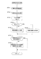
Next, the operation in the present embodiment will be described with reference to the flowcharts shown in FIGS. This operation is executed by the
図5に示すフローに入ると、まず、初期化を行う(S501)。初期化として、ここでは、点灯Flagを0にする。この点灯Flagは、EVF139の表示パネルが消灯状態から点灯状態に切り替わったことを示すフラグである。
When the flow shown in FIG. 5 is entered, first, initialization is performed (S501). As initialization, here, the lighting Flag is set to zero. The lighting flag is a flag indicating that the display panel of the
初期化を行うと、次に、アイセンサ出力を取得する(S502)。前述したようにアイセンサ141は、EVF139の接眼部近傍に配置されており、このステップでは、アイセンサ141の出力を取得する。このアイセンサ141の出力に基づいて、撮影者がEVF139を覗いているか否かが分かる。
Once initialization is performed, an eye sensor output is acquired (S502). As described above, the
アイセンサ出力を取得すると、次に、アイセンサ出力がEVF表示か否かを判定する(S503)。ここでは、ステップS502において取得したアイセンサ出力によって、撮影者がEVF139を覗いているか否かを判定する。
Once the eye sensor output is acquired, it is next determined whether or not the eye sensor output is EVF display (S503). Here, it is determined whether the photographer is looking into the
ステップS503における判定の結果、アイセンサ出力がEVF表示でなかった場合、すなわち、撮影者がEVF139を覗いていない場合には、点灯Flagを0とする(S511)。この場合には、ステップS504以下におけるEVF139によるEVF表示は行わず、点灯Flagを0にすると、このフローを終了する。
If the result of determination in step S503 is that the eye sensor output is not EVF display, that is, if the photographer is not looking into the
一方、ステップS503における判定の結果、アイセンサ出力がEVF表示の場合には、点灯Flagが0か否かを判定する(S504)。最初、ステップS501において、点灯Flagは0に設定されていることから、初期化後、初めて、アイセンサ出力がEVF表示となった場合には、点灯Flagは0である。また、一度、アイセンサ出力がEVF表示となると、ステップS505において点灯Flagは1になる。 On the other hand, if the result of determination in step S503 is that the eye sensor output is EVF display, it is determined whether or not the lighting flag is 0 (S504). First, since the lighting flag is set to 0 in step S501, the lighting flag is 0 when the eye sensor output becomes EVF display for the first time after initialization. Further, once the eye sensor output becomes EVF display, the lighting flag becomes 1 in step S505.
ステップS504における判定の結果、点灯Flagが0の場合には、点灯Flagを1にする(S505)。点灯Flagが0の場合には、それまで消灯状態であり、ステップS503においてアイセンサ出力がEVF表示に切り替わり、これから点灯状態に切り換えるために、点灯Flagを1にする。 If the result of determination in step S504 is that the lighting flag is 0, the lighting flag is set to 1 (S505). When the lighting flag is 0, the lighting flag is off until then, and the eye sensor output is switched to EVF display in step S503, and the lighting flag is set to 1 in order to switch to the lighting state.
ステップS505において点灯Flagを1にすると、次に、点灯時間(t)タイマを開始させる(S506)。本実施形態においては、EVF139の色味を決める白色点は、当初は予め決められている初期白色点であり、所定時間経過後に、撮影環境の光源情報に基づいて算出された目標白色点となるようにしている。このステップにおいて計時動作を開始した点灯時間タイマ(t)は、このための時間を計測する。なお、このタイマの初期値はt=0である。
If the lighting flag is set to 1 in step S505, then the lighting time (t) timer is started (S506). In the present embodiment, the white point that determines the color of the
ステップS506において、点灯時間(t)タイマの計時動作を開始すると、白色点算出1を行う(S507)。ここでは、EVF139に最初に表示する際の表示パネルの白色点を算出する。この白色点算出1の詳しい動作については、図6を用いて後述する。
In step S506, when the timing operation of the lighting time (t) timer is started,
一方、ステップS504における判定の結果、点灯Flagが1の場合には、点灯時間(t)を取得する(S508)。前述したように、ステップS506において、点灯タイマの計時動作を開始しているので、このステップでは、計時動作を開始してからの点灯タイマ時間(t)を取得する。 On the other hand, if the result of determination in step S504 is that the lighting flag is 1, the lighting time (t) is acquired (S508). As described above, since the timing operation of the lighting timer is started in step S506, the lighting timer time (t) after the timing operation is started is acquired in this step.
ステップS508において点灯時間(t)を取得すると、次に、白色点算出2を行う(S509)。点灯Flagが1の場合には、既にEVF139は点灯状態にあり、点灯してから時間が経過している。そこで、このステップでは、経過時間に応じて白色点を算出する。この白色点算出2の詳しい動作については、図8を用いて後述する。
If the lighting time (t) is acquired in step S508, white point calculation 2 is then performed (S509). When the lighting flag is 1, the
ステップS507における白色点算出1、またはステップS509における白色点算出2を行うと、次にEVF表示を行う(S510)。ここでは、ステップS507またはS509において算出された白色点に応じた色味でEVF表示を行う。EVF表示を行うと、ステップS502に戻る。
If
このように、図5に示すフローチャートにおいては、撮影者がEVF139を覗いて観察している場合であって(S503Yes)、初期化後、初めてEVF139を覗いた場合には、点灯時間(t)タイマの計時動作を開始させると共に白色点算出1を行い(S506、S507)、この白色点算出1に基づいてEVF表示を行う(S510)。そして、白色点算出1に基づいてEVF表示を行った後に、撮影者がEVF139を引き続き覗いている場合には、点灯時間(t)に応じて白色点算出2を行い(S508、S509)、この白色点算出2に基づいてEVF表示を行う(S510)。撮影者がEVF139を覗かなくなると(S503No)、点灯Flagを0にして(S511)、このフローを終了する。
In this way, in the flowchart shown in FIG. 5, when the photographer is looking through the EVF 139 (S503 Yes), and when looking at the
なお、この図5のフローにおいては、説明の都合上、EVF表示を終えた段階で終了としている。しかし、実際には、カメラ本体の背面に配置されたLCD135に表示を切り替え、またLCD135に表示中にアイセンサ141から撮影者の目がEVF139に近づき、EVF表示に切り替えると判断された場合には、再度、ステップS501から処理を実行する。
Note that the flow in FIG. 5 ends when EVF display is completed for convenience of explanation. However, in actuality, when the display is switched to the
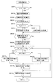
次に、図6を用いて、ステップS507における白色点算出1の詳しい動作について説明する。この白色点算出1は、図5に示したように、EVF139の表示パネルが消灯状態から点灯状態に切り替わる際に実行される。
Next, detailed operation of the
この白色点算出1のフローに入ると、まず、初期白色点(Ws)を取得する(S601)。ここでの初期白色点は、カメラとして予め設定しているデフォルトの白色点でもよいし、図7に示すように撮影光源情報を元に算出した白色点でもよい。デフォルトの白色点を用いる場合には、予めフラッシュメモリ125に記憶しておきこの値を読み出す事になる。その際の初期白色点(Ws)としては、例えば、CIEが規定するD65や、写真の昼光(太陽光)として一般的な約5500Kを使用する。
If the flow of this
初期白色点(Ws)を取得すると、次に、白色点変更変化率(ΔW,Δt)を取得する(S602)。白色点変化率は、単位時間(Δt)当たりの色温度の変化量(ΔW)を示し、白色点を変更する際の変更変化率がフラッシュメモリ125に記憶されているので、この変更変化率を読み出す。変更変化率情報としては、白色点の変更量を意味する白色点変更ステップΔWと、そのΔWの変更を行う頻度に関する変更間隔Δtを保持しているとする。ここでの変更変化率は、オートホワイトバランス設定時に画像のWBゲインの変更変化率を参考に決めればよい。例えば、オートホワイトバランスが、200msに1回の変更で3秒以内に収束するよう変更する場合には、これを考慮し白色点変更変化率を決めてもよい。
Once the initial white point (Ws) has been acquired, the white point change rate of change (ΔW, Δt) is then acquired (S602). The white point change rate indicates the change amount (ΔW) of the color temperature per unit time (Δt), and the change rate when the white point is changed is stored in the
ステップS602において、白色点変更変化率(ΔW,Δt)を取得すると、次に、パネル白色点(W)の設定を行い、W=Wsとする(S603)。ここでは、EVF139の表示パネルの白色点(W)として、ステップS601において取得した初期白色点(Ws)を設定する。
If the white point change rate of change (ΔW, Δt) is acquired in step S602, then the panel white point (W) is set, and W = Ws is set (S603). Here, the initial white point (Ws) acquired in step S601 is set as the white point (W) of the display panel of the
表示パネルの白色点(W)の設定を行うと、次に、直前白色点(W’)の更新を行い、W’=Wとする(S604)。ここでは、以降の処理において使用するため、直前白色点(W’)に、ステップS603において設定したEVF139の表示パネルの白色点(W)を設定する。
Once the white point (W) of the display panel has been set, the previous white point (W ′) is updated, and W ′ = W is set (S604). Here, the white point (W) of the display panel of the
直前白色点(W’)の更新を行うと、次に、直前点灯時間(t’)の更新を行い、t’=tとする(S605)。ここでは、以降の処理において使用するため、直前点灯時間(t’)に、ステップS506(図5参照)で設定した点灯時間(t)を設定する。直前点灯時間(t’)の更新を行うと、元のフローに戻る。 When the previous white point (W ′) is updated, the previous lighting time (t ′) is updated, and t ′ = t is set (S605). Here, for use in subsequent processing, the lighting time (t) set in step S506 (see FIG. 5) is set as the previous lighting time (t ′). When the last lighting time (t ′) is updated, the flow returns to the original flow.
次に、図7を用いて、ステップS601の初期白色点(Ws)取得の詳しい動作について説明する。図7に示すフローに入ると、まず、撮影光源情報を取得する(S701)。ここでは、初期白色点として、D65や5500K等の固定の白色点でなく、目標白色点と同様に、光源情報を取得する。 Next, a detailed operation for obtaining the initial white point (Ws) in step S601 will be described with reference to FIG. If the flow shown in FIG. 7 is entered, first, photographing light source information is acquired (S701). Here, the light source information is acquired as the initial white point, not the fixed white point such as D65 or 5500K, but the target white point.
撮影光源情報を取得すると、次に、初期白色点(Ws)を算出する(S702)。ここでは、ステップS701において取得した撮影光源情報に基づいて、初期白色点(Ws)を算出する。この場合、後述するステップS803(図8)の目標白色点(Wt)も撮影光源情報を元に算出した白色点となるため、EVF139の点灯時には、白色点の変更動作は行なわれない事になる。
Once the photographic light source information is acquired, an initial white point (Ws) is calculated (S702). Here, the initial white point (Ws) is calculated based on the imaging light source information acquired in step S701. In this case, since the target white point (Wt) in step S803 (FIG. 8) described later is also a white point calculated based on the photographing light source information, the white point changing operation is not performed when the
しかし、元々、ステップS802の撮影光源情報と、ステップS803の目標白色点(Wt)算出は、ステップS602において取得した変更間隔Δt毎に実施される。そのため、EVF139を覗いている際に、撮影環境の光源が変わった場合などは、それに対応して目標白色点(Wt)が変化することになり、それに追従するように、時間に応じ、EVF139の表示パネルの白色点(Wt)も変化する。
However, originally, the photographing light source information in step S802 and the target white point (Wt) calculation in step S803 are performed at every change interval Δt acquired in step S602. For this reason, when the light source of the shooting environment changes while looking into the
ステップS702において初期白色点(Ws)を算出すると、次に、Aフラグ(flg_A)を取得とする(S703)。Aフラグとしては、例えば、EVF139に表示する画像自体に色味を残すか否かを設定するための色味残しフラグの有無を用いてもよい。EVF139に表示するための画像データは、画像処理の段階でWB(ホワイトバランス)処理がなされており、その際、電球など色味の強い光源においては、色味をあえて残す「色味残し処理」が行われている場合がある。このステップにおけるフラグ設定では、画像データに対するWB処理として、色味残し有りで処理された画像データに対しては、flg_A=1とし、一方、色味残し無しで処理された画像データに対しては、flg_A=0とする。
Once the initial white point (Ws) is calculated in step S702, the A flag (flg_A) is acquired (S703). As the A flag, for example, the presence or absence of a color-remaining flag for setting whether or not to leave a color in the image displayed on the
また、ステップS703におけるAフラグ取得では、ユーザのカメラメニュー画面での設定や専用釦の操作状態に基づいて、Aフラグを取得するようにしても良い。さらに、画像データのWB処理におけるゲイン値を用いて、所定の値よりも大きいまたは小さい場合に色味残し無し(flg_A=0)と判断しても良いし、WB処理の際のRGBデータを用いたRGB空間に所定のエリアを設けて、そのエリアから外れる場合に、色味残し無し(flg_A=0)と判断しても良い。メニュー画面や専用釦を用いた場合には、ユーザの意図を正確に反映できるメリットがあり、WBゲインを用いる場合には、カメラ内部で自動的に判定できるメリットがある。 In the acquisition of the A flag in step S703, the A flag may be acquired based on the setting on the user's camera menu screen or the operation state of the dedicated button. Further, by using the gain value in the WB processing of the image data, it may be determined that there is no tint remaining (flg_A = 0) when it is larger or smaller than a predetermined value, or RGB data at the time of WB processing is used. If a predetermined area is provided in the existing RGB space and the area deviates from the area, it may be determined that there is no remaining color (flg_A = 0). When the menu screen or the dedicated button is used, there is an advantage that the user's intention can be accurately reflected, and when the WB gain is used, there is an advantage that the determination can be made automatically inside the camera.
ステップS703において、Aフラグの取得を行うと、次にAフラグが1か否かを判定する(S704)。ここでは、ステップS703において取得したAフラグ(flg_A)に基づいて判定する。 If the A flag is acquired in step S703, it is next determined whether or not the A flag is 1 (S704). Here, the determination is made based on the A flag (flg_A) acquired in step S703.
ステップS704における判定の結果、Aフラグ(flg_A)が1でなかった場合には(すなわち、flg_A=0)、色順応範囲(Q1)を取得する(S705)。画像のWB処理として、色味残し無しで処理された画像データをEVFパネルに表示する場合、色づいて見える環境下では、見た目通り色づいて見せるために、EVFパネルの白色点設定の範囲としては、色づいて見せることを想定した色順応範囲(Q1)を取得する。色順応範囲Q1は、図17に示すように、色順応範囲Q2によりも狭い範囲である。 If the result of determination in step S704 is that the A flag (flg_A) is not 1 (that is, flg_A = 0), the chromatic adaptation range (Q1) is acquired (S705). In the case where image data processed without leaving a color tone is displayed on the EVF panel as an image WB process, the EVF panel has a white point setting range in order to display the color as it appears in an environment where the color is visible. A chromatic adaptation range (Q1) that is assumed to be colored is acquired. As shown in FIG. 17, the chromatic adaptation range Q1 is a narrower range than the chromatic adaptation range Q2.
一方、ステップS704における判定の結果、Aフラグ(flg_A)が1であった場合には(すなわち、flg_A=1)、色順応範囲(Q2)を取得する(S706)。画像のWB処理として、色味残し有りで処理された画像データをEVFパネルに表示する場合、既に画像データの方で色味残しを行っている。そのため、色づいて見える環境下では、見た目通り色づいて見せるうえで、EVFパネルの白色点設定の範囲としては、色づいて見せる必要はなく、それを考慮した色順応範囲(Q2)を取得する。色順応範囲Q1は、図17に示すように、色順応範囲Q1によりも広い範囲である。 On the other hand, if the result of determination in step S704 is that the A flag (flg_A) is 1 (that is, flg_A = 1), the chromatic adaptation range (Q2) is acquired (S70 6 ). As image WB processing, when image data processed with color retention is displayed on the EVF panel, the image data has already been subjected to color retention. For this reason, in an environment where the colors are visible, it is not necessary to show the colors as the white point setting range of the EVF panel in order to show the colors as it looks, and the chromatic adaptation range (Q2) taking that into consideration is acquired. As shown in FIG. 17, the chromatic adaptation range Q1 is wider than the chromatic adaptation range Q1.
このようにステップS705〜S706において、色順応範囲を変更しているので、画像データ自体の色味残し処理の影響と、EVF白色点での色味残し処理の影響が二重になることを防止できる。すなわち、色味残し処理のされた画像データを、色味残し処理を考慮されたEVF白色点のEVFパネルで画像を表示すると、撮影画像の色味を適正に表示することができなくなるが、本実施形態では、色順応範囲を変更することにより、この問題を解消することができる。 As described above, since the chromatic adaptation range is changed in steps S705 to S706, it is possible to prevent the influence of the color-remaining process on the image data itself and the influence of the color-remaining process on the EVF white point from being doubled. it can. That is, if the image data that has been subjected to the tint-remaining process is displayed on the EVF panel of the EVF white point that has been considered for the tint-remaining process, the color of the photographed image cannot be displayed properly. In the embodiment, this problem can be solved by changing the chromatic adaptation range.
ステップS705またはS706にて、色順応範囲Q1またはQ2を取得すると、次に、初期白色点(Ws)が色順応範囲か否かを判定する(S707)。ここでは、ステップS702において算出した初期白色点(Ws)が、ステップS705またはS706で取得した色順応範囲内か否かを判定する。 If the chromatic adaptation range Q1 or Q2 is acquired in step S705 or S706, it is next determined whether or not the initial white point (Ws) is in the chromatic adaptation range (S707). Here, it is determined whether or not the initial white point (Ws) calculated in step S702 is within the chromatic adaptation range acquired in step S705 or S706.
ステップS707における判定の結果、初期白色点(Ws)が色順応範囲内にない場合には、初期白色点が色順応範囲に収まるよう初期白色点(Ws)を色順応範囲内の点に変更する(S708)。この初期白色点(Ws)の変更については、図12を用いて後述する。 If the result of determination in step S707 is that the initial white point (Ws) is not within the chromatic adaptation range, the initial white point (Ws) is changed to a point within the chromatic adaptation range so that the initial white point is within the chromatic adaptation range. (S708). The change of the initial white point (Ws) will be described later with reference to FIG.
なお、ステップS707における判定の結果、初期白色点(Ws)が色順応範囲内にある場合には、初期白色点(Ws)は変更することなく、その値をそのまま適用する。ステップS708において初期白色点(Ws)の変更を行うと、またはステップS707における判定の結果、初期白色点(Ws)が色順応範囲内の場合には、初期白色点(Ws)取得のフローを終了し、元のフローに戻る。 If the result of determination in step S707 is that the initial white point (Ws) is within the chromatic adaptation range, the initial white point (Ws) is applied without change. If the initial white point (Ws) is changed in step S708, or if the initial white point (Ws) is within the chromatic adaptation range as a result of the determination in step S707, the flow of acquiring the initial white point (Ws) is terminated. And return to the original flow.
次に、図8を用いて、ステップS509における白色点算出2の詳しい動作について説明する。この白色点算出2は、図5に示したように、既にEVF139の表示パネルが点灯された状態で、次の画像を表示する際の白色点算出処理である。
Next, the detailed operation of white point calculation 2 in step S509 will be described with reference to FIG. This white point calculation 2 is white point calculation processing when the next image is displayed in a state where the display panel of the
白色点算出2のフローに入ると、まず、t−t’>Δtであるか否かを判定する(S801)。ここでは、ステップS508(図5参照)で取得した現在の点灯時間(t)と、直前点灯時間(t’)の差が、変更間隔Δtよりも大きいか否かを判定する。この判定の結果、小さかった場合には、白色点算出2のフローを終了し、元のフローに戻る。 If the flow of white point calculation 2 is entered, it is first determined whether or not t−t ′> Δt is satisfied (S801). Here, it is determined whether or not the difference between the current lighting time (t) acquired in step S508 (see FIG. 5) and the previous lighting time (t ′) is larger than the change interval Δt. If the result of this determination is that it is smaller, the flow of white point calculation 2 is terminated, and the flow returns to the original flow.
ステップS801における判定の結果、t−t’>Δtであった場合には、次に、撮影光源情報を取得する(S802)。光源情報は、撮像素子103からのRGBデータ、または専用の光源検知用センサの検知信号から取得する。
If the result of determination in step S801 is that t−t ′> Δt, then imaging light source information is acquired (S802). The light source information is acquired from RGB data from the
撮影光源情報を取得すると、次に、目標白色点(Wt)を算出する(S803)。目標白色点(Wt)の算出は、得られる光源情報により異なる。例えば、光源センサとして、特開2009−296102や特開2011−211317に開示されているような透過率の異なるセンサモジュール/カラーセンサを用いて光源のスペクトル情報が得られる場合には、そのスペクトル情報S(λ)と、CIE1931−2degで規定されたXYZ等色関するX(λ),Y(λ),Z(λ)を元に、三刺激値X,Y,Zを算出し(下記(1)式〜(3)式参照)、その値からxy平面での色度x,yを算出すれば(下記(4)式、(5)式参照)、相関色温度を算出できる。 Once the photographic light source information is acquired, the target white point (Wt) is calculated (S803). The calculation of the target white point (Wt) varies depending on the obtained light source information. For example, when spectral information of a light source is obtained using a sensor module / color sensor having different transmittances as disclosed in Japanese Patent Application Laid-Open Nos. 2009-296102 and 2011-212317 as the light source sensor, the spectral information is obtained. Tristimulus values X, Y, and Z are calculated based on S (λ) and X (λ), Y (λ), and Z (λ) related to XYZ and the like specified by CIE1931-2deg ((1 If the chromaticity x, y on the xy plane is calculated from the value (see formulas (4) and (5) below), the correlated color temperature can be calculated.
X=s(λ)*X(λ) ・・・(1)
Y=s(λ)*Y(λ) ・・・(2)
Z=s(λ)*Z(λ) ・・・(3)
x=X/(X+Y+Z) ・・・(4)
y=Y/(X+Y+Z) ・・・(5)
X = s (λ) * X (λ) (1)
Y = s (λ) * Y (λ) (2)
Z = s (λ) * Z (λ) (3)
x = X / (X + Y + Z) (4)
y = Y / (X + Y + Z) (5)
また、光源センサでも、スペクトルではなく、可視光W(VL)と赤外光W(IR)の比率を検出するものがある。蛍光灯の場合には、一般に赤外光を含まないために、W(IR)/W(VL)が小さくなり、電球などのフラッドランプの場合には、太陽光などの昼光系の光源に比べ、W(IR)/W(VL)が大きくなる。 Some light source sensors detect not the spectrum but the ratio of visible light W (VL) to infrared light W (IR). In the case of a fluorescent lamp, since it generally does not contain infrared light, W (IR) / W (VL) becomes small. In the case of a flood lamp such as a light bulb, it is used as a daylight-type light source such as sunlight. In comparison, W (IR) / W (VL) increases.
このような可視光と赤外光の比率を検知する光源センサの場合には、画像のWBゲイン算出で用いられる光源推定と併用し、判定の際に、光源センサの出力結果を元に、推定方法を変更したり、光源毎のウエイトを変更して、最終的な色温度を推定すればよい。 In the case of such a light source sensor that detects the ratio of visible light to infrared light, it is used together with light source estimation used in calculating the WB gain of an image, and estimation is performed based on the output result of the light source sensor. The final color temperature may be estimated by changing the method or changing the weight for each light source.
ステップS803において目標白色点(Wt)を算出すると、次に、ステップS703と同様に、Aフラグ(flg_A)を取得する(S804)。続いて、ステップS704と同様に、flg_A=1か否かを判定し(S805)、この判定の結果flg_A=1でなかった場合には、ステップS705と同様に、色順応範囲(Q1)を取得し(S806)、一方、flg_A=1の場合には、ステップS706と同様に、色順応範囲(Q2)を取得する(S807)。 Once the target white point (Wt) is calculated in step S803, the A flag (flg_A) is acquired next, as in step S703 (S804). Subsequently, as in step S704, it is determined whether or not flg_A = 1 (S805). If the result of this determination is not flg_A = 1, the chromatic adaptation range (Q1) is acquired as in step S705. On the other hand, if flg_A = 1, the chromatic adaptation range (Q2) is acquired as in step S706 (S807).
ステップS806またはS807において、色順応範囲の取得を行うと、次に、目標白色点(Wt)が色順応範囲か否かを判定する(S808)。ここでは、ステップS803において取得した目標白色点(Wt)が、ステップS806またはS807において取得した色順応範囲にあるか否かを判定する。 Once the chromatic adaptation range is acquired in step S806 or S807, it is next determined whether or not the target white point (Wt) is within the chromatic adaptation range (S808). Here, it is determined whether or not the target white point (Wt) acquired in step S803 is within the chromatic adaptation range acquired in step S806 or S807.
ステップS808における判定の結果、目標白色点(Wt)が色順応範囲内にない場合には、目標白色点が色順応範囲内に収まるよう目標白色点(Wt)を色順応範囲内の点に変更する(S809)。この変更については、図12を用いて後述する。なお、ステップS808における判定の結果、目標白色点(Wt)が色順応範囲内にある場合には、目標白色点(Wt)は変更することなく、その値をそのまま適用する。 If the result of determination in step S808 is that the target white point (Wt) is not within the chromatic adaptation range, the target white point (Wt) is changed to a point within the chromatic adaptation range so that the target white point is within the chromatic adaptation range. (S809). This change will be described later with reference to FIG. If the result of determination in step S808 is that the target white point (Wt) is within the chromatic adaptation range, the target white point (Wt) is applied as it is without being changed.
ステップS809において目標白色点(Wt)の変更を行うと、またはステップS808における判定の結果、目標白色点(Wt)が色順応範囲内の場合には、次に、|W’−Wt|>ΔWか否かを判定する(S810)。ここでは、ステップS604もしくは後述するステップS814において設定した直前白色点(W’)と、ステップS803において算出した目標白色点(Wt)の差分の絶対値が、ステップS602において取得した白色点変更ステップΔWよりも大きいか否かを判定する。この判定の結果、差分の絶対値が白色点変更ステップΔWよりも小さい場合には、既に目標白色点に近い設定となっているため、ステップS811〜S814をスキップし、ステップS815に進む。 If the target white point (Wt) is changed in step S809 or if the result of determination in step S808 is that the target white point (Wt) is within the chromatic adaptation range, then | W′−Wt |> ΔW It is determined whether or not (S810). Here, the absolute value of the difference between the immediately preceding white point (W ′) set in step S604 or step S814 described later and the target white point (Wt) calculated in step S803 is the white point changing step ΔW acquired in step S602. It is judged whether it is larger than. As a result of this determination, if the absolute value of the difference is smaller than the white point changing step ΔW, the setting is already close to the target white point, so steps S811 to S814 are skipped and the process proceeds to step S815.
一方、ステップS810における判定の結果、差分の絶対値が白色点変更ステップΔWよりも大きい場合には、直前白色点(W’)が目標白色点(Wt)よりも大きいか否かを判定する(S811)。 On the other hand, if the result of determination in step S810 is that the absolute value of the difference is greater than the white point changing step ΔW, it is determined whether or not the immediately preceding white point (W ′) is greater than the target white point (Wt) ( S811).
ステップS811における判定の結果、W’>Wtであった場合には、パネル白色点(W)を、W=W’−ΔWに基づいて設定する(S812)。ここでは、直前白色点(W’)から白色点変更ステップΔWを減算することにより、目標白色点に近づけた値を、EVF139の表示パネルの白色点(W)とする。
If the result of determination in step S811 is that W ′> Wt, the panel white point (W) is set based on W = W′−ΔW (S812). Here, a value that is close to the target white point by subtracting the white point changing step ΔW from the previous white point (W ′) is set as the white point (W) of the display panel of the
一方、ステップS811における判定の結果、W’>Wtでなかった場合には、パネル白色点(W)を、W=W’+ΔWに基づいて設定する(S813)。ここでは、直前白色点(W’)に白色点変更ステップΔWを加算することにより、目標白色点に近づけた値を、EVF139の表示パネルの白色点(W)とする。
On the other hand, if it is determined in step S811 that W ′> Wt is not satisfied, the panel white point (W) is set based on W = W ′ + ΔW (S813). Here, the white point (W) of the
ステップS812またはS813において、パネル白色点(W)を設定すると、次に、直前白色点(W’)の更新を行い、W’=Wとする(S814)。ここでは、次回以降、ステップS810、S811、S812、S813において使用する直前白色点(W’)の値を更新する。 If the panel white point (W) is set in step S812 or S813, then the previous white point (W ') is updated and W' = W is set (S814). Here, the value of the immediately preceding white point (W ′) used in steps S810, S811, S812, and S813 is updated after the next time.
また直前白色点(W’)の更新を行うと、またはステップS810における判定の結果、差分値がΔWよりも小さかった場合には、次に、直前点灯時間(t’)の更新を行い、t’=tとする(S815)。ここでは、次回以降、ステップS801において使用する直前点灯時間(t’)の値を更新する。ステップS815において直前点灯時間(t’)の更新を行うと、またはステップS801における判定の結果、t−t’がΔtよりも小さかった場合には、元のフローに戻る。 If the previous white point (W ′) is updated, or if the result of determination in step S810 is that the difference value is smaller than ΔW, then the previous lighting time (t ′) is updated, and t '= T (S815). Here, the value of the last lighting time (t ′) used in step S801 is updated after the next time. When the previous lighting time (t ′) is updated in step S815, or when t-t ′ is smaller than Δt as a result of the determination in step S801, the process returns to the original flow.
このように、図6ないし図8に示すフローチャートにおいては、観察環境の光源を、撮影環境の光源に対応した表示モニタの白色点に設定することにより、観察画像の色味を最終的な撮影画像の色味に近くなるように処理を行っていた。さらに、人の目は撮影環境に順応した状態になっているため、色順応を考慮した処理を行うようにしている。 As described above, in the flowcharts shown in FIGS. 6 to 8, the light source of the observation environment is set to the white point of the display monitor corresponding to the light source of the shooting environment, so that the color of the observation image is finally taken. The process was performed so as to be close to the color. Further, since the human eye is in a state adapted to the shooting environment, processing is performed in consideration of chromatic adaptation.
ここで、色順応とは、環境変化により対応する人の目あるいは脳の仕組みであり、環境(光源)の違いにより全体が色づいている場合に、人は多少の色味の違いであれば、その違いを吸収し、白いものは白と認識する特性である。通常、光源によって同じ画像であっても色味は異なり(図9の中段の「光源による画像の色味の変化」参照)、光源の色温度が低い場合には赤味を帯び、色温度が高くなると青味を帯びてくる。 Here, chromatic adaptation is the mechanism of the human eye or brain that responds to changes in the environment, and when the whole is colored due to differences in the environment (light source), if the person has a slight color difference, This is a characteristic that absorbs the difference and recognizes white as white. Usually, even if the image is the same depending on the light source, the color tone is different (see “change in image color tone due to the light source” in the middle of FIG. 9). When it gets higher, it becomes bluish.
それに対し、人の目は順応するため、ある範囲まで「白」を「白」と認識し、その範囲を超えたところで色かぶりしたように感じる始める。図9に示した例では、横軸に光源の色温度をとり、代表的な光源7〜10を示している。この色温度に対して、領域A2は人の目の色順応範囲であり、「白」を「白」と認識する。領域A2より低色温度の領域A1では、「白」を赤っぽく感じる領域であり、領域A2より高色温度領域のA3では、「白」を青っぽく感じる領域である。
On the other hand, because the human eye adapts, “white” is recognized as “white” up to a certain range, and it begins to feel as if the color is cast beyond that range. In the example shown in FIG. 9, the color temperature of the light source is taken on the horizontal axis, and representative
そこで、本実施形態においては、人の目の色順応範囲と撮影環境の光源を元にEVF139の表示パネルの白色点の設定を行い、最適な色味となるようにした。
Therefore, in the present embodiment, the white point of the display panel of the
なお、図5ないし図8に示したフローチャートにおいて、Aフラグ及び色順応範囲として、「画像の色味残しの有り無し」を用いる例を説明した。しかし、それ以外にも、例えば、「被写界のBv値」から撮影光源情報の妥当性を判断し、撮影光源情報の信頼性が低い場合には、色順応範囲を狭め、間違った撮影光源情報の影響を受けないようにしてもよい。また、「焦点距離」情報から画像のWBゲインと撮影光源情報の乖離を判断し、望遠シーンなど撮影環境と画像の環境が大きく異なる場合に起こる撮影光源情報の間違いを配慮し、色順応範囲を狭めることで、影響を受けないようにしてもよい。 In the flowcharts shown in FIGS. 5 to 8, the example in which “there is no image color residue” is used as the A flag and the color adaptation range. However, other than that, for example, if the validity of the photographic light source information is determined from the “Bv value of the object scene” and the reliability of the photographic light source information is low, the chromatic adaptation range is narrowed, and the wrong photographic light source You may make it not receive the influence of information. Also, the difference between the WB gain of the image and the photographic light source information is judged from the “focal length” information, and the chromatic adaptation range is set in consideration of the mistake in the photographic light source information that occurs when the shooting environment and the image environment such as a telephoto scene are greatly different By narrowing, it may not be affected.
さらに、「光源情報の時間的な変化」により、短時間で光源が頻繁に変化するような場合には、この不自然さを軽減するため色順応範囲を狭め、安定した白色点表示をするようにしてもよい。さらに、「シーン判別」や「被写体判別」により、風景や室内撮影に応じて色順応範囲を設定することで、環境に依らず自然な見えを実現するようにしてもよい。さらに、「ジャイロ」や「動き判別」により、パンニングなどに伴う被写界の急な変化を検出し、色味の安定性を優先した色順応範囲の設定に変更してもよい。 In addition, when the light source changes frequently in a short time due to “temporal changes in the light source information”, the chromatic adaptation range is narrowed to reduce the unnaturalness and a stable white point display is performed. It may be. Furthermore, a natural appearance can be realized regardless of the environment by setting a chromatic adaptation range according to the scenery or indoor shooting by “scene discrimination” or “subject discrimination”. Furthermore, a sudden change in the object scene due to panning or the like may be detected by “gyro” or “motion determination”, and the color adaptation range may be changed so as to give priority to color stability.
このように、様々な状況に応じた対応をとり、その状況に応じた色順応範囲を設定の仕方と判別基準を適用することが望ましい。これにより、ファインダを覗いた直後の違和感を解消しつつ、ファインダを覗き続けたばあいでも、その変化に追従し安定したファインダの見えを実現することができる。 In this way, it is desirable to take measures according to various situations, and to apply a method and determination criteria for setting a color adaptation range according to the situations. Accordingly, it is possible to realize a stable view of the finder following the change even if the user keeps looking through the finder while eliminating the uncomfortable feeling immediately after looking through the finder.
次に、色順応範囲について、図10ないし図12を用いて説明する。これまでの説明にあたって、初期白色点、目標白色点、色温度追従範囲を「色温度」という一次元の指標として扱ってきたが、必ずしも一次元の指標でなくてもよい。例えば、色を表す際に一般的なxy色度図でもよい。図10は、xy色度図で表した色温度曲線を示し、この色温度曲線は黒体軌跡もしくは黒体輻射という。 Next, the chromatic adaptation range will be described with reference to FIGS. In the description so far, the initial white point, the target white point, and the color temperature tracking range have been treated as a one-dimensional index “color temperature”, but it is not necessarily a one-dimensional index. For example, a general xy chromaticity diagram may be used when expressing colors. FIG. 10 shows a color temperature curve represented by an xy chromaticity diagram, and this color temperature curve is called a black body locus or black body radiation.
図11は、図10の一部(x座標の0.2〜0.55、y座標の0.2〜0.5の範囲)を拡大した図である。xy色度図上に色順応範囲Q(破線で示した範囲)を指定しておき、撮影光源情報により、xy平面上での光源位置を算出する。なお、範囲Q1は図7のS705及び図8のS806の色順応範囲(Q1)に対応する範囲であり、また、範囲Q2は図7のステップS706及び図8のステップS807の色順応範囲(Q2)に対応する範囲である。 FIG. 11 is an enlarged view of a part of FIG. 10 (range of x coordinate 0.2 to 0.55, y coordinate 0.2 to 0.5). A chromatic adaptation range Q (a range indicated by a broken line) is designated on the xy chromaticity diagram, and a light source position on the xy plane is calculated based on photographing light source information. The range Q1 is a range corresponding to the color adaptation range (Q1) of S705 of FIG. 7 and S806 of FIG. 8, and the range Q2 is the color adaptation range (Q2 of Step S706 of FIG. 7 and Step S807 of FIG. 8). ).
また、図12は、算出された光源位置の例として、光源L1と光源L2を示している。色順応を考慮する場合、デフォルト白色点としてD65や5500Kを指定し、デフォルト白色点Pdとする。なお、破線は、色順応範囲Q1またはQ2を示している。破線をQ1またはQ2に置き換えればよい。 FIG. 12 shows a light source L1 and a light source L2 as examples of the calculated light source position. When chromatic adaptation is considered, D65 or 5500K is designated as the default white point, and is set as the default white point Pd. A broken line indicates the chromatic adaptation range Q1 or Q2. The broken line may be replaced with Q1 or Q2.
デフォルト白色点Pdと、各光源位置(図12の例では、光源L1、L2)を結ぶ直線または曲線と、色順応範囲Qの境界とが交差する点付近(図12の例では白色点位置P1、P2)を、EVF139の表示パネルの白色点(W)とすればよい。すなわち、ステップS708、S809において、初期白色点(Ws)および目標白色点(Wt)を書き換えているが、これらの初期白色点および目標白色点は、破線で示した色順応範囲Qの境界が交差する点付近(図12の例では白色点位置P1、P2)に相当する。なお、図12の例では、白色点位置P1は色順応範囲Q内にある例であり、白色点位置P2は境界上にある例である。また、デフォルト白色点Pdと光源L1とは曲線で結ぶ例であり、デフォルト白色点と光源L2とは直線で結ぶ例である。
Near the point where the straight line or curve connecting the default white point Pd and each light source position (in the example of FIG. 12, the light sources L1 and L2) intersects the boundary of the chromatic adaptation range Q (in the example of FIG. 12, the white point position P1 , P2) may be the white point (W) of the
図12に示す例において、色順応範囲外である光源L1、L2に対応する色温度をそのまま初期白色点および目標白色点にしてしまうと、もともと人の目で色かぶり環境であるため過補正となり、不自然に見える場合がある。そこで、デフォルト白色点Pdと光源L1、L2を結ぶ線と色順応範囲Qの交差点もしくは色順応範囲Q内を初期白色点位置および目標白色点とする事で、実際に色かぶりして見える光源においても、同様に色かぶりした見た目通りの色を再現することが出来る。 In the example shown in FIG. 12, if the color temperature corresponding to the light sources L1 and L2 outside the chromatic adaptation range is set to the initial white point and the target white point as they are, it is overcorrected because it is originally a color cast environment with human eyes. May look unnatural. Therefore, an intersection of the default white point Pd and the light sources L1 and L2 and the chromatic adaptation range Q or the chromatic adaptation range Q is set as the initial white point position and the target white point, so that the light source that actually appears as a color cast. In the same way, it is possible to reproduce the color as it looks like the color cast.
なお、図12に示す例においては、初期白色点(Ws)および目標白色点(Wt)として、デフォルト白色点Pdと光源L1等を結ぶ直線または曲線と色順応範囲Qの交差点または色順応範囲Q内の位置を設定しているが、これに限らず、例えば色順応範囲Qと光源を最短距離で結べる点等、初期白色点を色順応範囲内に設定できる方法であればよい。 In the example shown in FIG. 12, as the initial white point (Ws) and the target white point (Wt), a straight line or curve connecting the default white point Pd and the light source L1 and the chromatic adaptation range Q or the chromatic adaptation range Q However, the present invention is not limited to this, and any method may be used as long as the initial white point can be set within the chromatic adaptation range, such as a point where the chromatic adaptation range Q and the light source can be connected with the shortest distance.
このように、本実施形態においては、マイクロコンピュータ121が、人が白いものを白と認知できる光源の範囲である順応光源範囲に対応する白色点範囲を順応追従範囲Qとし、その順応追従範囲Qを予め指定しておき、初期白色点(Ws)および目標白色点(Wt)が順応追従範囲Qから外れるか否かを判定する判定手段としての機能し、この判定手段により、撮影光源情報に基づく初期白色点もしくは目標白色点が順応追従範囲Qから外れると判定された場合には(図7S707、図8のS808)、順応追従範囲Q内に新しい初期白色点および新しい目標白色点を設定する(図7のS708、図8のS809、図12)。このため、人が「白」を「白」と感じられる範囲では「白」を「白」として再現され、色づいて感じられる範囲では色づいて再現されるため、見たものと同様な色味を再現することができる。
As described above, in this embodiment, the
次に、本発明の一実施形態の変形例について、図13ないし図16を用いて説明する。本発明の一実施形態においては、Aフラグに応じて色順応範囲Q1、Q2を取得し、以後、この色順応範囲を用いて白色点を設定していた。これに対して、本変形例においては、色順応範囲を時間と共に変更するようにしている。 Next, a modification of one embodiment of the present invention will be described with reference to FIGS. In one embodiment of the present invention, the chromatic adaptation ranges Q1 and Q2 are acquired according to the A flag, and thereafter, the white point is set using the chromatic adaptation range. On the other hand, in this modification, the chromatic adaptation range is changed with time.
色順応範囲を時間と共に変更しているのは、以下の理由による。EVF139を見ながら撮影する場合、ファインダで構図・画角を確認し、ファインダで色味を調整する等の動作を行い、最終的に撮影動作に入る。この間、撮影者はファインダ内の被写体像に次第に見慣れてくるので、色順応範囲も次第に広くなってくる。そこで、本変形例においては、時間と共に、色順応範囲を変更するようにしている。
The reason why the chromatic adaptation range is changed with time is as follows. When taking a picture while viewing the
本発明の一実施形態における図1に示す構成、図5、図6に示すフローチャートは、本変形例においても使用し、図7の初期白色点(Ws)取得、図8の白色点算出2のフローチャートを図13、図14に示すフローチャートに置き換える点で相違する(他に、図15および図16における説明が追加される)。そこで、この相違点について説明する。なお、これらのフローチャートに示す動作は、マイクロコンピュータ121がフラッシュメモリ125に記憶されているプログラムに従って実行する。
The configuration shown in FIG. 1 and the flowcharts shown in FIGS. 5 and 6 in the embodiment of the present invention are also used in this modification, and the initial white point (Ws) acquisition in FIG. 7 and the white point calculation 2 in FIG. The difference is that the flowcharts are replaced with the flowcharts shown in FIGS. 13 and 14 (in addition, descriptions in FIGS. 15 and 16 are added). Therefore, this difference will be described. The operations shown in these flowcharts are executed by the
図13に示す初期白色点(Ws)取得のフローに入ると、図7のS701と同様に撮影光源情報を取得し(S701)、図7のS702と同様に初期白色点(Ws)を取得する(S702)。これらのステップにおける動作は、図7のフローと同様であることから、詳しい説明を省略する。 When the flow for obtaining the initial white point (Ws) shown in FIG. 13 is entered, the photographing light source information is obtained in the same manner as S701 in FIG. 7 (S701), and the initial white point (Ws) is obtained in the same manner as S702 in FIG. (S702). Since the operation in these steps is the same as the flow of FIG. 7, detailed description thereof is omitted.
続いて、色順応範囲(Q4s)を取得する(S1301)。図7に示した初期白色点(Ws)取得のフローでは、初期白色点(Ws)を決める際の色順応範囲をフラグAに基づいて、予め決められた色順応範囲を選択していた。これに対して、本変形例では、ファインダEVF139を覗いた直後の色順応範囲としてQ4sを取得する。この色順応範囲Q4sは、フラッシュメモリ125に記憶されているので、この値を読み出す。なお、色順応範囲Q4sは、ユーザの好み等に応じて、適宜変更できるようにしてもよい。
Subsequently, the chromatic adaptation range (Q4s) is acquired (S1301). In the initial white point (Ws) acquisition flow shown in FIG. 7, a predetermined color adaptation range is selected based on the flag A as the color adaptation range when determining the initial white point (Ws). On the other hand, in this modification, Q4s is acquired as the chromatic adaptation range immediately after looking through the
色順応範囲(Q4s)を取得すると、次に、初期白色点(Ws)が色順応範囲(Q4s)内か否かの判定を行う(S1302)。ここでは、ステップS702において算出した初期白色点(Ws)が、ステップS1302において取得した色順応範囲(Q4s)の範囲内に入っているか否かを判定する。 When the chromatic adaptation range (Q4s) is acquired, it is next determined whether or not the initial white point (Ws) is within the chromatic adaptation range (Q4s) (S1302). Here, it is determined whether or not the initial white point (Ws) calculated in step S702 is within the chromatic adaptation range (Q4s) acquired in step S1302.
ステップS1302における判定の結果、初期白色点(Ws)が色順応範囲(Q4s)内にない場合には、色順応範囲に収まるよう初期白色点(Ws)を色順応範囲(Q4s)内の点に変更する(S1303)。この初期白色点(Ws)の変更については、前述の図12の説明と同様である。 If the result of determination in step S1302 is that the initial white point (Ws) is not within the chromatic adaptation range (Q4s), the initial white point (Ws) is set to a point within the chromatic adaptation range (Q4s) so as to be within the chromatic adaptation range. Change (S1303). The change of the initial white point (Ws) is the same as described above with reference to FIG.
なお、ステップS1302における判定の結果、初期白色点(Ws)が色順応範囲(Q4s)内にある場合には、初期白色点(Ws)は変更することなく、その値をそのまま適用する。 If the result of determination in step S1302 is that the initial white point (Ws) is within the chromatic adaptation range (Q4s), the initial white point (Ws) is applied without change.
ステップS1303において初期白色点(Ws)の変更を行うと、またはステップS707における判定の結果、初期白色点(Ws)が色順応範囲内の場合には、直前色順応範囲(Q’)の更新、Q’=Q4sを行う(S1304)。ここでは、直前の色順応範囲(Q’)として、色順応範囲(Q4s)を記憶しておく。直前色順応範囲(Q’)の更新を行うと、初期白色点(Ws)取得のフローを終了し、元のフローに戻る。 When the initial white point (Ws) is changed in step S1303, or when the initial white point (Ws) is within the chromatic adaptation range as a result of the determination in step S707, the immediately previous chromatic adaptation range (Q ′) is updated. Q ′ = Q4s is performed (S1304). Here, the chromatic adaptation range (Q4s) is stored as the immediately preceding chromatic adaptation range (Q '). When the immediately previous color adaptation range (Q ′) is updated, the initial white point (Ws) acquisition flow is terminated, and the flow returns to the original flow.
次に、図14を用いて、本変形例の白色点算出2の動作について説明する。本変形例の白色点算出は、図8に示すフローチャートにおいて、ステップS804〜S809を、図14のステップS1401〜S1403に置き換える点で相違し、他のステップは同様である。そこで、相違点を中心に説明する。 Next, the operation of white point calculation 2 of the present modification will be described with reference to FIG. The white point calculation of this modification is different in that the steps S804 to S809 are replaced with the steps S1401 to S1403 in FIG. 14 in the flowchart shown in FIG. 8, and the other steps are the same. Therefore, the difference will be mainly described.
図14に示すフローに入り、t−t’>Δtであるか否かを判定し(S801)、この判定の結果、t−t’>Δtであった場合には、次に、撮影光源情報を取得し(802)、目標白色点(Wt)を取得する(S803)。 The flow shown in FIG. 14 is entered, and it is determined whether or not t−t ′> Δt (S801). If the result of this determination is that t−t ′> Δt, then the shooting light source information (802), and a target white point (Wt) is acquired (S803).
目標白色点(Wt)を取得すると、次に、色順応範囲(Q4)を取得する(S1401)。本変形例において、変更間隔Δt毎に、色順応範囲(Q4s)から色順応範囲(Q4e)に向けて色順応範囲(Q4)の範囲を変化させている(図16参照)。このステップにおいて、変化した色順応範囲(Q4)を取得する。色順応範囲(Q4)取得の詳しい動作については、図15を用いて後述する。 Once the target white point (Wt) is acquired, the chromatic adaptation range (Q4) is acquired (S1401). In this modification, the range of the chromatic adaptation range (Q4) is changed from the chromatic adaptation range (Q4s) to the chromatic adaptation range (Q4e) at every change interval Δt (see FIG. 16). In this step, the changed chromatic adaptation range (Q4) is acquired. Detailed operation for obtaining the chromatic adaptation range (Q4) will be described later with reference to FIG.
色順応範囲(Q4)を取得すると、次に、目標白色点(Wt)が色順応範囲(Q4)か否かを判定する(S1402)。ここでは、ステップS803において算出した目標白色点(Wt)が、ステップS1401において取得した色順応範囲(Q4)の範囲内にあるか否かを判定する。 Once the chromatic adaptation range (Q4) is acquired, it is next determined whether or not the target white point (Wt) is within the chromatic adaptation range (Q4) (S1402). Here, it is determined whether or not the target white point (Wt) calculated in step S803 is within the color adaptation range (Q4) acquired in step S1401.
ステップS1402における判定の結果、目標白色点(Wt)が色順応範囲(Q4)内にない場合には、色順応範囲内に収まるように目標白色点(Wt)を色順応範囲(Q4)内の点に変更する(S1403)。この変更については、前述の図12における説明と同様である。なお、ステップS1402における判定の結果、目標白色点(Wt)が色順応範囲(Q4)内にある場合には、目標白色点(Wt)は変更することなく、その値をそのまま適用する。 If the result of determination in step S1402 is that the target white point (Wt) is not within the chromatic adaptation range (Q4), the target white point (Wt) is within the chromatic adaptation range (Q4) so as to be within the chromatic adaptation range. The point is changed (S140 3 ). This change is the same as described above with reference to FIG. If the target white point (Wt) is within the chromatic adaptation range (Q4) as a result of the determination in step S1402, the target white point (Wt) is applied without change.
ステップS1403において目標白色点(Wt)の変更を行うと、またはステップS1402における判定の結果、目標白色点(Wt)が色順応範囲(Q4)内の場合には、次に、|W’−Wt|>ΔWか否かを判定する(S810)。このステップS810〜S815は、図8における動作と同様であることから、詳しい説明を省略する。 If the target white point (W t ) is changed in step S1403 or if the result of determination in step S1402 is that the target white point (W t ) is within the chromatic adaptation range (Q4), then | W ′ It is determined whether or not −Wt |> ΔW (S810). Steps S810 to S815 are the same as the operation in FIG.
次に、図15を用いて、ステップS1401における色順応範囲(Q4)取得の詳しい動作について説明する。図15のフローに入ると、まず、色順応範囲変更ステップ(ΔQ)を取得する(S1501)。本変形例においては、撮影者がファインダEVF139を覗いている時間に応じて、色順応範囲を段階的に変更する。このステップでは、色順応範囲を変更する際の変更ステップ(ΔQ)を読み込む。この変更ステップ(ΔQ)は、フラッシュメモリ125に予め記憶されているので、この値を読み出す。
Next, a detailed operation of acquiring the chromatic adaptation range (Q4) in step S1401 will be described with reference to FIG. Upon entering the flow of FIG. 15, first acquires the color adaptation range change steps (ΔQ) (S1501). In this modification, the chromatic adaptation range is changed stepwise in accordance with the time during which the photographer is looking into the
色順応範囲変更ステップ(ΔQ)を取得すると、次に、色順応範囲(Q4e)を取得する(S1502)。この色順応範囲(Q4e)は、ファインダEVF139を覗いて十分に時間が経過した場合の最終的な色順応範囲である(図16参照)。この色順応範囲(Q4e)は、フラッシュメモリ125に予め記憶されているので、この値を読み出す。
If the chromatic adaptation range changing step (ΔQ) is acquired, then the chromatic adaptation range (Q4e) is acquired (S1502). This chromatic adaptation range (Q4e) is the final chromatic adaptation range when a sufficient amount of time has passed through the viewfinder EVF 139 (see FIG. 16). Since this chromatic adaptation range (Q4e) is stored in advance in the
色順応範囲(Q4e)を取得すると、次に、|Q’−Q4e|>ΔQか否かを判定する(S1503)。ここでは、最新の色順応範囲(S1304、S1507参照)とステップS1502で取得した最終の色順応範囲(Q4e)との差分の絶対値が、ステップS1501で取得した変更ステップよりも大きいか否かを判定する。 Once the chromatic adaptation range (Q4e) is acquired, it is next determined whether or not | Q'-Q4e |> ΔQ (S1503). Here, whether or not the absolute value of the difference between the latest color adaptation range (see S1304 and S1507) and the final color adaptation range (Q4e) acquired in step S1502 is larger than the change step acquired in step S1501. judge.
ステップS1503における判定の結果、|Q’−Q4e|>ΔQでなかった場合には、色順応範囲(Q4)をQ4=Q’に設定する(S1508)。すなわち、この場合は、直前の色順応範囲(Q4)と最終の色順応範囲(Q4e)との差分がΔQ以内であることから、直前の色順応範囲(Q’)を、色順応範囲(Q4)に設定する。 If the result of determination in step S1503 is that | Q'-Q4e |> ΔQ, the chromatic adaptation range (Q4) is set to Q4 = Q '(S1508). That is, in this case, since the difference between the immediately preceding chromatic adaptation range (Q4) and the final chromatic adaptation range (Q4e) is within ΔQ, the immediately preceding chromatic adaptation range (Q ′) is changed to the chromatic adaptation range (Q4). ).
一方、ステップS1503における判定の結果、|Q’−Q4e|>ΔQの場合には、次に、Q’>Q4eか否かを判定する(S1504)。本変形例においては、直前の色順応範囲Q’と最終の色順応範囲(Q4)を比較し、最終的な色順応範囲(Q4e)に対して、直前の色順応範囲(Q’)が大きければ範囲を小さくし、一方、直前の色順応範囲(Q’)が小さければ範囲を大きくしている。このステップでは、このための大小関係を判定している。 On the other hand, if | Q′−Q4e |> ΔQ as a result of the determination in step S1503, it is next determined whether or not Q ′> Q4e (S1504). In this modification, the previous color adaptation range (Q ′) is compared with the final color adaptation range (Q4e) by comparing the previous color adaptation range Q ′ with the final color adaptation range (Q4). If the previous color adaptation range (Q ′) is small, the range is increased. In this step, the magnitude relationship for this is determined.
ステップS1504における判定の結果、Q’>Q4eの場合には、色順応範囲(Q4)として、Q4=Q’−ΔQを設定する(S1505)。一方、Q’>Q4eでない場合には、色順応範囲(Q4)として、Q4=Q’+ΔQを設定する(S1506)。色順応範囲(Q4)を設定すると、次に、直前色順応範囲(Q’)として、Q’=Q4と更新する(S1507)。 If the result of determination in step S1504 is that Q '> Q4e, Q4 = Q'-ΔQ is set as the chromatic adaptation range (Q4) (S1505). On the other hand, if Q ′> Q4e is not satisfied, Q4 = Q ′ + ΔQ is set as the chromatic adaptation range (Q4) (S1506). If the chromatic adaptation range (Q4) is set, next, the previous chromatic adaptation range (Q ') is updated as Q' = Q4 (S1507).
ステップS1507またはS1508の処理を行うと、色順応範囲(Q4)取得のフローを終了し、元のフローに戻る。 When the processing in step S1507 or S1508 is performed, the flow for obtaining the chromatic adaptation range (Q4) is terminated and the process returns to the original flow.
次に、図16を用いて、本変形例における色順応範囲について説明する。撮影者がファインダEVF139を覗いた当初は、色順応範囲Q4sであり、また最終の色順応範囲はQ4eである。本変形例においては、変更間隔Δt毎に色順応範囲Q4が、最終の色順応範囲Q4eに達するまで、ΔQ単位で変化させている。従って、撮影者の目の慣れに応じて、次第に、色順応範囲が広がっていく。
Next, the chromatic adaptation range in this modification will be described with reference to FIG. When the photographer looks into the
以上、説明したように、ファインダEVF139を覗き続けていると、少なからずファインダEVF139内の環境に順応してくる。そのため、ファインダEVF139を覗いた直後と、暫く覗き続けた後では、色順応範囲が異なってくる。本変形例では、ファインダEVF139を覗いてからの時間に応じて色順応範囲も変更させている。このため、人間の目の順応性に配慮し、環境に依らず撮影画像の色味を事前に確認することができる。
As described above, if the user continues to look into the
以上の説明においては、色順応範囲の例として、xy平面を用いて説明したが、必ずしもxy平面でなくてもよい。例えば、YUV平面で色順応範囲を指定するようにしてもよい。YUV空間での相関色温度は、黒体軌跡Bに垂直な直線状となるため、相関色温度を考慮して色順応範囲を指定する場合には、YUVの方が容易な場合もある。 In the above description, the xy plane has been described as an example of the chromatic adaptation range, but the xy plane is not necessarily required. For example, the chromatic adaptation range may be specified on the YUV plane. Since the correlated color temperature in the YUV space is a straight line perpendicular to the black body locus B, YUV may be easier when the chromatic adaptation range is specified in consideration of the correlated color temperature.
また、YUV平面以外にも、WBゲインとして用いられることの多いRGBを用いて、R/G−B/G平面で色順応範囲を指定するようにしてもよい。但し、この場合には、撮像素子の分光特性やレンズの透過率によって、黒体軌跡Bが変化するため、色順応エリアもこのことを考慮し、反映させる必要がある。色順応範囲として設定する際の色空間は、これ以外にも様々考えられるが、最適な空間を選択すればよい。 In addition to the YUV plane, RGB, which is often used as a WB gain, may be used to specify the chromatic adaptation range on the R / GB / G plane. However, in this case, since the black body locus B changes depending on the spectral characteristics of the image sensor and the transmittance of the lens, the chromatic adaptation area needs to be reflected in consideration of this. There are various other color spaces that can be set as the chromatic adaptation range, but an optimal space may be selected.
以上説明したように、本発明の一実施形態や変形例においては、EVF139に対するユーザの接眼/非接眼をアイセンサ141によって検出し(S502、S503)、アイセンサ141によりユーザの接眼が検出された場合は、撮影環境の光源情報に基づいてEVF139の表示パネルの初期白色点(Ws)もしくは目標白色点(Wt)を算出し(S702、S803)、初期白色点で電子ビューファインダ表示パネルの表示を開始させた後、EVF139の表示パネルの白色点を初期白色点(Ws)から変化させて目標白色点(Wt)となるように制御している。このように、撮影環境の光源情報に基づく表示パネルの白色点となるように制御しているため、環境に依らず撮影画像の色味を事前に確認することができる。
As described above, in one embodiment or modification of the present invention, when the
また、本発明の一実施形態や変形例においては、初期白色点(例えば、図7のS702のWs)もしくは目標白色点(例えば、図8のS803のWt)が順応追従範囲から外れると判定された場合には(例えば、図8のS808のYes)、順応範囲内に入るように新しい初期白色点もしくは新しい目標白色点を算出する(例えば、図7のS708、図8のS809)。このため、人間の目の順応性に配慮し、環境に依らず撮影画像の色味を事前に確認することができる。 In one embodiment or modification of the present invention, the initial white point (for example, Ws in S702 in FIG. 7) or the target white point (for example, Wt in S803 in FIG. 8) is determined to be out of the adaptation tracking range. In the case (for example, Yes in S808 in FIG. 8), a new initial white point or a new target white point is calculated so as to fall within the adaptation range (for example, S708 in FIG. 7 and S809 in FIG. 8). For this reason, considering the adaptability of the human eye, the color of the captured image can be confirmed in advance regardless of the environment.
なお、本発明の一実施形態や変形例においては、撮影のための機器として、デジタルカメラを用いて説明したが、カメラとしては、デジタル一眼レフカメラでもコンパクトデジタルカメラでもよく、ビデオカメラ、ムービーカメラのような動画用のカメラでもよく、さらに、携帯電話、スマートフォーンや携帯情報端末(PDA:Personal Digital Assist)、ゲーム機器等に内蔵されるカメラでも構わない。いずれにしても、EVFを備える機器であれば、本発明を適用することができる。 In the embodiment and the modification of the present invention, the digital camera is used as the photographing device. However, the camera may be a digital single-lens reflex camera or a compact digital camera, and a video camera or movie camera. It may be a camera for moving images such as a mobile phone, a smart phone, a personal digital assistant (PDA), a game device, or the like. In any case, the present invention can be applied to any device provided with EVF.
また、本明細書において説明した技術のうち、主にフローチャートで説明した制御に関しては、プログラムで設定可能であることが多く、記録媒体や記録部に収められる場合もある。この記録媒体、記録部への記録の仕方は、製品出荷時に記録してもよく、配布された記録媒体を利用してもよく、インターネットを介してダウンロードしたものでもよい。 Of the techniques described in this specification, the control mainly described in the flowchart is often settable by a program and may be stored in a recording medium or a recording unit. The recording method for the recording medium and the recording unit may be recorded at the time of product shipment, may be a distributed recording medium, or may be downloaded via the Internet.
また、特許請求の範囲、明細書、および図面中の動作フローに関して、便宜上「まず」、「次に」等の順番を表現する言葉を用いて説明したとしても、特に説明していない箇所では、この順で実施することが必須であることを意味するものではない。 In addition, regarding the operation flow in the claims, the specification, and the drawings, even if it is described using words expressing the order such as “first”, “next”, etc. It does not mean that it is essential to implement in this order.
本発明は、上記実施形態にそのまま限定されるものではなく、実施段階ではその要旨を逸脱しない範囲で構成要素を変形して具体化できる。また、上記実施形態に開示されている複数の構成要素の適宜な組み合わせにより、種々の発明を形成できる。例えば、実施形態に示される全構成要素の幾つかの構成要素を削除してもよい。さらに、異なる実施形態にわたる構成要素を適宜組み合わせてもよい。 The present invention is not limited to the above-described embodiments as they are, and can be embodied by modifying the constituent elements without departing from the scope of the invention in the implementation stage. In addition, various inventions can be formed by appropriately combining a plurality of components disclosed in the embodiment. For example, you may delete some components of all the components shown by embodiment. Furthermore, constituent elements over different embodiments may be appropriately combined.
1・・・カメラ、3・・・画像データ、5・・・画像、5a−5j・・・画像、7−10・・・光源、11・・・モニタ、100・・・カメラ本体、101・・・メカニカルシャッタ、103・・・撮像素子、105・・・アナログ処理部、107・・・A/D変換部、109・・・バス、111・・・画像処理部、111a・・・WB補正部、111b・・・同時化処理部、111c・・・色再現処理部、111d・・・NR処理部、113・・・AE処理部、115・・・AF処理部、117・・・AWB処理部、119・・・JPEG処理部、121・・・マイクロコンピュータ、123・・・操作部、125・・・フラッシュメモリ、127・・・SDRAM、129・・・メモリI/F、131・・・記録媒体、133・・・LCDドライバ、135・・・LCD、137・・・電子ビューファインダ(EVF)ドライバ、139・・・電子ビューファインダ(EVF)、141・・・アイセンサ、200・・・交換式レンズ、201・・・撮影レンズ、203・・・絞り、205・・・ドライバ、207・・・マイクロコンピュータ、209・・・フラッシュメモリ、999・・・I/F
DESCRIPTION OF
Claims (11)
上記電子ビューファインダの表示パネルの初期白色点として予め保持する記憶手段と、
撮影環境の光源情報に基づいて上記電子ビューファインダの表示パネルの目標白色点を算出する算出手段と、
上記電子ビューファインダに対するユーザの接眼/非接眼を検出する接眼検出手段と、
上記ユーザが白いものを白と認知できる光源の範囲である順応光源範囲に対応する白色点範囲を順応追従範囲とし、その順応追従範囲を予め指定しておき、上記初期白色点もしくは上記目標白色点が上記順応追従範囲から外れるか否かを判定する判定手段と、
上記接眼検出手段により上記ユーザの接眼が検出された場合は、上記初期白色点で上記電子ビューファインダの表示パネルの表示を開始させた後、上記電子ビューファインダ表示パネルの白色点を上記初期白色点から経時変化させて上記目標白色点となるように制御する表示制御手段と、
を備え、
上記判定手段により、上記初期白色点もしくは上記目標白色点が上記順応追従範囲から外れると判定された場合には、上記算出手段は、上記順応追従範囲内に入るように新しい初期白色点もしくは新しい目標白色点として算出することを特徴とする撮像装置。 An imaging apparatus having an electronic viewfinder that enables an image displayed on a display unit to be visually recognized through an eyepiece lens,
Storage means for holding in advance as an initial white point of the display panel of the electronic viewfinder;
A calculating means for calculating a target white point of the display panel of the electronic viewfinder based on light source information of a shooting environment;
Eyepiece detecting means for detecting a user's eyepiece / non-eyepiece with respect to the electronic viewfinder;
The white point range corresponding to the adaptation light source range, which is a light source range in which the user can recognize white as white, is set as the adaptation tracking range, the adaptation tracking range is designated in advance, and the initial white point or the target white point Determining means for determining whether or not is out of the adaptation tracking range;
When the eyepiece of the user is detected by the eyepiece detection means, the display of the display panel of the electronic viewfinder is started at the initial white point, and then the white point of the electronic viewfinder display panel is changed to the initial white point. Display control means for controlling from time to time so as to be the target white point,
With
When the determination means determines that the initial white point or the target white point is out of the adaptation tracking range, the calculation means calculates a new initial white point or a new target so as to fall within the adaptation tracking range. An imaging device characterized by calculating as a white point.
上記判定手段は、第1の順応追従範囲と、上記第1の順応追従範囲とは異なる第2の順応追従範囲を備え、上記順応追従範囲設定手段で設定された上記切り換えフラグに基づいて、上記第1の順応追従範囲と上記第2の順応追従範囲の切り換えを判定し、
上記算出手段は、上記第1の順応追従範囲、もしくは上記第2の順応追従範囲内に入るように新しい初期白色点、もしくは新しい目標白色点として算出する、
ことを特徴とする請求項1に記載の撮像装置。 Furthermore, it has an adaptation tracking range setting means for setting a switching flag for switching the adaptation tracking range.
Said determination means comprises a first adaptation tracing range, with a different second adaptation tracing range is from the first adaptation tracing range, based on the switching flag that is set in the adaptation tracing range setting means, the Determining switching between the first adaptation tracking range and the second adaptation tracking range;
The calculation means calculates a new initial white point or a new target white point so as to fall within the first adaptation tracking range or the second adaptation tracking range.
The imaging apparatus according to claim 1.
上記表示制御手段は、予め指定された白色点変更変化率と上記接眼時間とに基づいて、上記電子ビューファインダ表示パネルの白色点の変化を制御することを特徴とする請求項1ないし6のいずれか1項に記載の撮像装置。 The eyepiece detecting means further comprises a time measuring means for measuring an eyepiece time as an elapsed time since the eyepiece of the user was detected,
7. The display control means according to claim 1, wherein the white point change of the electronic viewfinder display panel is controlled based on a white point change rate of change specified in advance and the eyepiece time. The imaging apparatus of Claim 1.
上記電子ビューファインダの表示パネルの初期白色点として予め保持する記憶手段と、
撮影環境の光源情報に基づいて上記電子ビューファインダの表示パネルの目標白色点を算出する算出手段と、
上記電子ビューファインダに対するユーザの接眼/非接眼を検出する接眼検出手段と、
上記ユーザが白いものを白と認知できる光源の範囲である順応光源範囲に対応する白色点範囲を順応追従範囲とし、その順応追従範囲を予め指定しておき、上記目標白色点もしくは上記初期白色点が上記順応追従範囲から外れるか否かを判定する判定手段と、
上記接眼検出手段により上記ユーザの接眼が検出された場合は、上記初期白色点で上記電子ビューファインダの表示パネルの表示を開始させた後、上記電子ビューファインダ表示パネルの白色点を上記初期白色点から経時変化させて上記目標白色点となるように制御する表示制御手段と、
を備え、
上記判定手段により、上記初期白色点もしくは上記目標白色点が上記順応追従範囲から外れると判定された場合には、上記算出手段は、上記順応追従範囲内に入るように新しい初期白色点もしくは新しい目標白色点として算出することを特徴とする電子ビューファインダ。 An electronic viewfinder in an imaging device that enables an image displayed on a display unit to be visually recognized through an eyepiece,
Storage means for holding in advance as an initial white point of the display panel of the electronic viewfinder;
A calculating means for calculating a target white point of the display panel of the electronic viewfinder based on light source information of a shooting environment;
Eyepiece detecting means for detecting a user's eyepiece / non-eyepiece with respect to the electronic viewfinder;
The white point range corresponding to the adaptation light source range, which is a light source range in which the user can recognize white as white, is set as the adaptation tracking range, and the adaptation tracking range is designated in advance, and the target white point or the initial white point Determining means for determining whether or not is out of the adaptation tracking range;
When the eyepiece of the user is detected by the eyepiece detection means, the display of the display panel of the electronic viewfinder is started at the initial white point, and then the white point of the electronic viewfinder display panel is changed to the initial white point. Display control means for controlling from time to time so as to be the target white point,
With
When the determination means determines that the initial white point or the target white point is out of the adaptation tracking range, the calculation means calculates a new initial white point or a new target so as to fall within the adaptation tracking range. An electronic viewfinder characterized by being calculated as a white point.
撮影環境の光源情報に基づいて上記電子ビューファインダの表示パネルの目標白色点を算出する算出ステップと、
上記電子ビューファインダに対するユーザの接眼/非接眼を検出する検出ステップと、
上記ユーザが白いものを白と認知できる光源の範囲である順応光源範囲に対応する白色点範囲を順応追従範囲とし、その順応追従範囲を予め指定しておき、上記目標白色点もしくは上記初期白色点が上記順応追従範囲から外れるか否かを判定する判定ステップと、
上記検出ステップにより上記ユーザの接眼が検出された場合は、上記初期白色点で上記電子ビューファインダの表示パネルの表示を開始させた後、上記電子ビューファインダ表示パネルの白色点を上記初期白色点から経時変化させて上記目標白色点となるように制御する表示制御ステップと、
を備え、
上記判定ステップにより、上記初期白色点もしくは上記目標白色点が上記順応追従範囲から外れると判定された場合には、上記算出ステップは、上記順応追従範囲内に入るように新しい初期白色点もしくは新しい目標白色点として算出することを特徴とする表示制御方法。 A display control method in an imaging apparatus, comprising: an electronic viewfinder that enables an image displayed on a display unit to be visually recognized through an eyepiece; and storage means that holds in advance as an initial white point of a display panel of the electronic viewfinder. ,
A calculation step of calculating a target white point of the display panel of the electronic viewfinder based on the light source information of the shooting environment;
A detection step of detecting an eyepiece / non-eyepiece of the user with respect to the electronic viewfinder;
The white point range corresponding to the adaptation light source range, which is a light source range in which the user can recognize white as white, is set as the adaptation tracking range, and the adaptation tracking range is designated in advance, and the target white point or the initial white point A determination step for determining whether or not is out of the adaptation tracking range;
When the eyepiece of the user is detected by the detection step, display of the display panel of the electronic viewfinder is started at the initial white point, and then the white point of the electronic viewfinder display panel is changed from the initial white point. A display control step for controlling the target white point to change over time,
With
When it is determined by the determination step that the initial white point or the target white point is out of the adaptation tracking range, the calculation step includes a new initial white point or a new target so as to fall within the adaptation tracking range. A display control method characterized by calculating as a white point.
撮影環境の光源情報に基づいて上記電子ビューファインダの表示パネルの目標白色点を算出する算出ステップと、
上記電子ビューファインダに対するユーザの接眼/非接眼を検出する検出ステップと、
上記ユーザが白いものを白と認知できる光源の範囲である順応光源範囲に対応する白色点範囲を順応追従範囲とし、その順応追従範囲を予め指定しておき、上記目標白色点もしくは上記初期白色点が上記順応追従範囲から外れるか否かを判定する判定ステップと、
上記検出ステップにより上記ユーザの接眼が検出された場合は、上記初期白色点で上記電子ビューファインダの表示パネルの表示を開始させた後、上記電子ビューファインダ表示パネルの白色点を上記初期白色点から経時変化させて上記目標白色点となるように制御する表示制御ステップと、
を備え、
上記判定ステップにより、上記初期白色点もしくは上記目標白色点が上記順応追従範囲から外れると判定された場合には、上記算出ステップは、上記順応追従範囲内に入るように新しい初期白色点もしくは新しい目標白色点として算出する、
ことをコンピュータに実行させることを特徴とする表示制御用プログラム。 Display control for executing a computer in an imaging apparatus having an electronic viewfinder that enables an image displayed on the display unit to be viewed through an eyepiece, and storage means that holds in advance as an initial white point of a display panel of the electronic viewfinder A program for
A calculation step of calculating a target white point of the display panel of the electronic viewfinder based on the light source information of the shooting environment;
A detection step of detecting an eyepiece / non-eyepiece of the user with respect to the electronic viewfinder;
The white point range corresponding to the adaptation light source range, which is a light source range in which the user can recognize white as white, is set as the adaptation tracking range, and the adaptation tracking range is designated in advance, and the target white point or the initial white point A determination step for determining whether or not is out of the adaptation tracking range;
When the eyepiece of the user is detected by the detection step, display of the display panel of the electronic viewfinder is started at the initial white point, and then the white point of the electronic viewfinder display panel is changed from the initial white point. A display control step for controlling the target white point to change over time,
With
When it is determined by the determination step that the initial white point or the target white point is out of the adaptation tracking range, the calculation step includes a new initial white point or a new target so as to fall within the adaptation tracking range. Calculate as white point,
A display control program which causes a computer to execute
Priority Applications (3)
| Application Number | Priority Date | Filing Date | Title |
|---|---|---|---|
| JP2013192015A JP6017389B2 (en) | 2013-09-17 | 2013-09-17 | Imaging apparatus, electronic viewfinder, display control method, and display control program |
| US14/482,054 US9232144B2 (en) | 2013-09-17 | 2014-09-10 | Imaging device, electronic viewfinder, and display control method |
| CN201410471608.2A CN104469134B (en) | 2013-09-17 | 2014-09-16 | Camera device, electronic viewfinder and display control method |
Applications Claiming Priority (1)
| Application Number | Priority Date | Filing Date | Title |
|---|---|---|---|
| JP2013192015A JP6017389B2 (en) | 2013-09-17 | 2013-09-17 | Imaging apparatus, electronic viewfinder, display control method, and display control program |
Publications (3)
| Publication Number | Publication Date |
|---|---|
| JP2015061120A JP2015061120A (en) | 2015-03-30 |
| JP2015061120A5 JP2015061120A5 (en) | 2016-06-02 |
| JP6017389B2 true JP6017389B2 (en) | 2016-11-02 |
Family
ID=52667619
Family Applications (1)
| Application Number | Title | Priority Date | Filing Date |
|---|---|---|---|
| JP2013192015A Expired - Fee Related JP6017389B2 (en) | 2013-09-17 | 2013-09-17 | Imaging apparatus, electronic viewfinder, display control method, and display control program |
Country Status (3)
| Country | Link |
|---|---|
| US (1) | US9232144B2 (en) |
| JP (1) | JP6017389B2 (en) |
| CN (1) | CN104469134B (en) |
Families Citing this family (6)
| Publication number | Priority date | Publication date | Assignee | Title |
|---|---|---|---|---|
| US10217438B2 (en) * | 2014-05-30 | 2019-02-26 | Apple Inc. | User interface and method for directly setting display white point |
| US9336582B1 (en) * | 2015-04-17 | 2016-05-10 | Google Inc. | Convolutional color correction |
| CN104994300A (en) * | 2015-07-20 | 2015-10-21 | 魅族科技(中国)有限公司 | Photographing method and terminal |
| JP6360979B2 (en) | 2015-11-18 | 2018-07-18 | 富士フイルム株式会社 | Imaging apparatus and control method thereof |
| US10701244B2 (en) * | 2016-09-30 | 2020-06-30 | Microsoft Technology Licensing, Llc | Recolorization of infrared image streams |
| DE102017109254A1 (en) * | 2017-04-28 | 2018-10-31 | Carl Zeiss Ag | digital camera |
Family Cites Families (7)
| Publication number | Priority date | Publication date | Assignee | Title |
|---|---|---|---|---|
| US6947079B2 (en) | 2000-12-22 | 2005-09-20 | Eastman Kodak Company | Camera having verification display with reverse white balanced viewer adaptation compensation and method |
| JP2004140736A (en) * | 2002-10-21 | 2004-05-13 | Minolta Co Ltd | Image pickup device |
| JP4126487B2 (en) * | 2002-11-08 | 2008-07-30 | 株式会社沖データ | Image conversion method and image conversion apparatus |
| US7755671B2 (en) * | 2007-04-23 | 2010-07-13 | Hewlett-Packard Development Company, L.P. | Correcting a captured image in digital imaging devices |
| JP5262378B2 (en) * | 2007-08-09 | 2013-08-14 | ペンタックスリコーイメージング株式会社 | Imaging device |
| JP5153441B2 (en) * | 2008-04-28 | 2013-02-27 | キヤノン株式会社 | Imaging apparatus, control method thereof, and program |
| JP4683132B2 (en) * | 2009-01-30 | 2011-05-11 | ブラザー工業株式会社 | Image processing apparatus, image processing program, and image processing method |
-
2013
- 2013-09-17 JP JP2013192015A patent/JP6017389B2/en not_active Expired - Fee Related
-
2014
- 2014-09-10 US US14/482,054 patent/US9232144B2/en not_active Expired - Fee Related
- 2014-09-16 CN CN201410471608.2A patent/CN104469134B/en not_active Expired - Fee Related
Also Published As
| Publication number | Publication date |
|---|---|
| US20150077587A1 (en) | 2015-03-19 |
| US9232144B2 (en) | 2016-01-05 |
| JP2015061120A (en) | 2015-03-30 |
| CN104469134A (en) | 2015-03-25 |
| CN104469134B (en) | 2018-01-16 |
Similar Documents
| Publication | Publication Date | Title |
|---|---|---|
| US10506173B2 (en) | Image capturing apparatus and control method thereof | |
| US8830348B2 (en) | Imaging device and imaging method | |
| US9473698B2 (en) | Imaging device and imaging method | |
| US8749653B2 (en) | Apparatus and method of blurring background of image in digital image processing device | |
| JP6017389B2 (en) | Imaging apparatus, electronic viewfinder, display control method, and display control program | |
| JP2014120844A (en) | Image processing apparatus and imaging apparatus | |
| US20140176775A1 (en) | Imaging device and imaging method | |
| JP2017022610A (en) | Image processing apparatus and image processing method | |
| JP2007124282A (en) | Imaging apparatus | |
| JP6137855B2 (en) | Imaging apparatus, imaging method, and program | |
| JP5569361B2 (en) | Imaging apparatus and white balance control method | |
| JP6319971B2 (en) | Imaging apparatus, control method therefor, program, and storage medium | |
| JP2007124278A (en) | Imaging apparatus | |
| JP5153441B2 (en) | Imaging apparatus, control method thereof, and program | |
| US20100259606A1 (en) | Imaging device and method for controlling imaging device | |
| JP2009033386A (en) | Photographing device and method | |
| JP5403087B2 (en) | Image processing device | |
| JP2007124280A (en) | Imaging apparatus | |
| JP2012227744A (en) | Imaging apparatus | |
| JP2010157873A (en) | Image pickup device, and control method of image pickup device | |
| JP6446102B2 (en) | Imaging apparatus, control method therefor, program, and storage medium | |
| JP2007124281A (en) | Imaging apparatus | |
| JP2015073165A (en) | Imaging device |
Legal Events
| Date | Code | Title | Description |
|---|---|---|---|
| A521 | Request for written amendment filed |
Free format text: JAPANESE INTERMEDIATE CODE: A523 Effective date: 20160404 |
|
| A621 | Written request for application examination |
Free format text: JAPANESE INTERMEDIATE CODE: A621 Effective date: 20160404 |
|
| A871 | Explanation of circumstances concerning accelerated examination |
Free format text: JAPANESE INTERMEDIATE CODE: A871 Effective date: 20160404 |
|
| A975 | Report on accelerated examination |
Free format text: JAPANESE INTERMEDIATE CODE: A971005 Effective date: 20160420 |
|
| A131 | Notification of reasons for refusal |
Free format text: JAPANESE INTERMEDIATE CODE: A131 Effective date: 20160628 |
|
| A521 | Request for written amendment filed |
Free format text: JAPANESE INTERMEDIATE CODE: A523 Effective date: 20160817 |
|
| TRDD | Decision of grant or rejection written | ||
| A01 | Written decision to grant a patent or to grant a registration (utility model) |
Free format text: JAPANESE INTERMEDIATE CODE: A01 Effective date: 20160907 |
|
| A61 | First payment of annual fees (during grant procedure) |
Free format text: JAPANESE INTERMEDIATE CODE: A61 Effective date: 20160928 |
|
| R151 | Written notification of patent or utility model registration |
Ref document number: 6017389 Country of ref document: JP Free format text: JAPANESE INTERMEDIATE CODE: R151 |
|
| R250 | Receipt of annual fees |
Free format text: JAPANESE INTERMEDIATE CODE: R250 |
|
| LAPS | Cancellation because of no payment of annual fees |