JP6013377B2 - Biological blood vessel parameter measuring device - Google Patents
Biological blood vessel parameter measuring device Download PDFInfo
- Publication number
- JP6013377B2 JP6013377B2 JP2013556134A JP2013556134A JP6013377B2 JP 6013377 B2 JP6013377 B2 JP 6013377B2 JP 2013556134 A JP2013556134 A JP 2013556134A JP 2013556134 A JP2013556134 A JP 2013556134A JP 6013377 B2 JP6013377 B2 JP 6013377B2
- Authority
- JP
- Japan
- Prior art keywords
- ultrasonic
- blood vessel
- axis
- ultrasonic sensor
- detection surface
- Prior art date
- Legal status (The legal status is an assumption and is not a legal conclusion. Google has not performed a legal analysis and makes no representation as to the accuracy of the status listed.)
- Active
Links
Images


Classifications
-
- A—HUMAN NECESSITIES
- A61—MEDICAL OR VETERINARY SCIENCE; HYGIENE
- A61B—DIAGNOSIS; SURGERY; IDENTIFICATION
- A61B8/00—Diagnosis using ultrasonic, sonic or infrasonic waves
- A61B8/44—Constructional features of the ultrasonic, sonic or infrasonic diagnostic device
- A61B8/4483—Constructional features of the ultrasonic, sonic or infrasonic diagnostic device characterised by features of the ultrasound transducer
- A61B8/4494—Constructional features of the ultrasonic, sonic or infrasonic diagnostic device characterised by features of the ultrasound transducer characterised by the arrangement of the transducer elements
-
- A—HUMAN NECESSITIES
- A61—MEDICAL OR VETERINARY SCIENCE; HYGIENE
- A61B—DIAGNOSIS; SURGERY; IDENTIFICATION
- A61B8/00—Diagnosis using ultrasonic, sonic or infrasonic waves
- A61B8/08—Detecting organic movements or changes, e.g. tumours, cysts, swellings
- A61B8/0891—Detecting organic movements or changes, e.g. tumours, cysts, swellings for diagnosis of blood vessels
-
- A—HUMAN NECESSITIES
- A61—MEDICAL OR VETERINARY SCIENCE; HYGIENE
- A61B—DIAGNOSIS; SURGERY; IDENTIFICATION
- A61B8/00—Diagnosis using ultrasonic, sonic or infrasonic waves
- A61B8/42—Details of probe positioning or probe attachment to the patient
- A61B8/4209—Details of probe positioning or probe attachment to the patient by using holders, e.g. positioning frames
- A61B8/4227—Details of probe positioning or probe attachment to the patient by using holders, e.g. positioning frames characterised by straps, belts, cuffs or braces
-
- A—HUMAN NECESSITIES
- A61—MEDICAL OR VETERINARY SCIENCE; HYGIENE
- A61B—DIAGNOSIS; SURGERY; IDENTIFICATION
- A61B8/00—Diagnosis using ultrasonic, sonic or infrasonic waves
- A61B8/44—Constructional features of the ultrasonic, sonic or infrasonic diagnostic device
- A61B8/4444—Constructional features of the ultrasonic, sonic or infrasonic diagnostic device related to the probe
- A61B8/4461—Features of the scanning mechanism, e.g. for moving the transducer within the housing of the probe
-
- A—HUMAN NECESSITIES
- A61—MEDICAL OR VETERINARY SCIENCE; HYGIENE
- A61B—DIAGNOSIS; SURGERY; IDENTIFICATION
- A61B8/00—Diagnosis using ultrasonic, sonic or infrasonic waves
- A61B8/52—Devices using data or image processing specially adapted for diagnosis using ultrasonic, sonic or infrasonic waves
- A61B8/5207—Devices using data or image processing specially adapted for diagnosis using ultrasonic, sonic or infrasonic waves involving processing of raw data to produce diagnostic data, e.g. for generating an image
Description
本発明は、生体血管パラメータ測定装置に関し、特にその生体血管パラメータ測定装置による血管パラメータの測定時の被測定者の不安を軽減させる技術に関するものである。 The present invention relates to a biological blood vessel parameter measuring device, and more particularly to a technique for reducing anxiety of a measurement subject when measuring blood vessel parameters by the biological blood vessel parameter measuring device.
生体血管パラメータ測定装置は、例えば特許文献1に示すように、被測定者の上腕(生体の一部)の皮膚上に超音波センサの検出面を接触させてその皮膚内の血管の血管パラメータたとえば血管径、血管断面積、血管壁厚、プラーク、血流速度などを測定するものである。
As shown in
また、特許文献1の生体血管パラメータ測定装置には、前記上腕が載置される受面を有する受台が備えられており、その受台上に載置された上腕の動脈上に超音波センサの検出面が押圧される。すなわち、前記上腕は、前記受台の受面と前記超音波センサの検出面との間に配置されその受面と検出面とに挟まれた状態で、前記生体血管パラメータ測定装置によりその血管の血管パラメータが測定される。また、前記超音波センサの検出面と前記上腕との間には、超音波損失を軽減するためのカップリング剤としてよく知られたゼリー(超音波ゼリー)が介在されている。
In addition, the biological blood vessel parameter measurement device of
ところで、上記のような特許文献1の生体血管パラメータ測定装置において、測定時に前記受台上の前記上腕に前記超音波センサの検出面が押圧されるので、被測定者は、その上腕が前記受面と前記検出面に挟まれているような感覚となり更に強く挟まれるのではないかという不安を感じる可能性があった。そのため、上記のような生体血管パラメータ測定装置では、被測定者の心理が不安定となって安定な測定ができない場合があるという問題があった。
By the way, in the biological blood vessel parameter measuring apparatus of
本発明は、以上の事情を背景として為されたものであって、その目的とするところは、血管パラメータの測定時の被測定者の不安を軽減させる生体血管パラメータ測定装置を提供することにある。 The present invention has been made in the background of the above circumstances, and an object of the present invention is to provide a biological blood vessel parameter measuring device that can reduce anxiety of a measurement subject when measuring blood vessel parameters. .
かかる目的を達成するための本発明の要旨とするところは、(a) 生体の一部の皮膚上に超音波センサを接触させてその皮膚内の血管の血管パラメータを測定する生体血管パラメータ測定装置であって、(b) 前記生体の一部が載置される受面を有する受台と、(c) 前記受台の受面に開口し、前記超音波センサの検出面がその開口内に位置するようにその超音波センサを収容する収容穴と、(d) 前記収容穴の開口内周に設けられて液状物質を収容し、前記超音波センサの検出面と前記受面に載置された前記生体の一部との間にその液状物質を介在させる液状物質貯留装置とを、含むことを特徴とする。 To achieve this object, the gist of the present invention is as follows: (a) a biological blood vessel parameter measuring device for measuring a blood vessel parameter of a blood vessel in the skin by contacting an ultrasonic sensor on a part of the skin of the living body; (B) a receiving table having a receiving surface on which a part of the living body is placed; and (c) an opening is formed in the receiving surface of the receiving table, and a detection surface of the ultrasonic sensor is in the opening. A receiving hole for receiving the ultrasonic sensor so as to be positioned, and (d) a liquid substance provided in the inner periphery of the opening of the receiving hole to be placed on the detection surface and the receiving surface of the ultrasonic sensor. And a liquid substance storage device that interposes the liquid substance with a part of the living body.
本発明の生体血管パラメータ測定装置によれば、(b) 前記生体の一部が載置される受面を有する受台と、(c) 前記受台の受面に開口し、前記超音波センサの検出面がその開口内に位置するようにその超音波センサを収容する収容穴と、(d) 前記収容穴の開口内周に設けられて液状物質を収容し、前記超音波センサの検出面と前記受面に載置された前記生体の一部との間にその液状物質を介在させる液状物質貯留装置とを含む。このため、前記生体の一部を前記受台の受面に載置させることによって、前記超音波センサーの検出面がその生体の一部の皮膚上に接触するので、前記生体の一部を前記受台に載置させた状態での前記血管パラメータの測定が可能となる。これによって、従来のような前記超音波センサの検出面と前記受台の受面とに押さえられた状態で血管パラメータが測定されるものに比較して、前記生体血管パラメータ測定装置は、前記生体の一部を前記受台の受面に載置させるだけであり、前記生体の一部を容易に離すことができるので、前記血管パラメータの測定時の被測定者の不安を軽減させることができる。 According to the biological blood vessel parameter measuring device of the present invention, (b) a receiving table having a receiving surface on which a part of the living body is placed, and (c) an opening on the receiving surface of the receiving table, the ultrasonic sensor A receiving hole for receiving the ultrasonic sensor so that the detection surface of the ultrasonic sensor is positioned in the opening; and (d) a detection surface of the ultrasonic sensor provided in the inner periphery of the opening for receiving the liquid substance. And a liquid substance storage device for interposing the liquid substance between the living body placed on the receiving surface and a part of the living body. Therefore, by placing a part of the living body on the receiving surface of the cradle, the detection surface of the ultrasonic sensor comes into contact with a part of the skin of the living body. The blood vessel parameter can be measured in a state where it is placed on a cradle. As a result, the biological blood vessel parameter measuring device is compared with the conventional device in which the blood vessel parameter is measured while being pressed by the detection surface of the ultrasonic sensor and the receiving surface of the cradle. Since only a part of the living body is placed on the receiving surface of the cradle and a part of the living body can be easily separated, anxiety of the measurement subject at the time of measuring the blood vessel parameter can be reduced. .
ここで、好適には、前記収容穴内に収容された超音波センサは、前記収容穴内に設けられた案内装置によって前記生体の動脈に対して交差するX軸方向に案内され且つX軸方向駆動装置により位置決めさせられる移動部材に支持されている。このため、前記超音波センサの前記X軸方向駆動装置による前記X軸方向の位置決めが可能となり、前記生体の一部内の血管と前記超音波センサとのずれが自動的に解消される。 Here, preferably, the ultrasonic sensor accommodated in the accommodation hole is guided in the X-axis direction intersecting the artery of the living body by a guide device provided in the accommodation hole and is driven in the X-axis direction. It is supported by the moving member positioned by. Therefore, the ultrasonic sensor can be positioned in the X-axis direction by the X-axis direction driving device, and the deviation between the blood vessel in a part of the living body and the ultrasonic sensor is automatically eliminated.
また、好適には、前記液状物質貯留装置は、外周部が前記収容穴の開口部内周縁に液密に固定され、且つ、内周部が前記超音波センサの検出面の周囲に液密に固定された弾性シートを備え、前記液状物質をその液状物質の液面が前記超音波センサの検出面よりも上となるようにその弾性シート上に貯留するものである。このため、測定時には、前記超音波センサの検出面と前記生体の一部との間に前記液状物質が前記液状物質貯留装置により常時介在されているので、従来のように前記液状物質が前記生体の一部から流れ落ちることなく、良好な血管の画像を連続的に得ることができる。 Preferably, in the liquid substance storage device, an outer peripheral portion is fixed in a liquid-tight manner to an inner peripheral edge of the opening of the receiving hole, and an inner peripheral portion is fixed in a liquid-tight manner around the detection surface of the ultrasonic sensor. The liquid material is stored on the elastic sheet so that the liquid surface of the liquid material is above the detection surface of the ultrasonic sensor. For this reason, at the time of measurement, the liquid substance is always interposed by the liquid substance storage device between the detection surface of the ultrasonic sensor and a part of the living body. A good blood vessel image can be continuously obtained without flowing down from a part of the blood vessel.
また、好適には、前記液状物質貯留装置は、前記液状物質が封入されて前記超音波センサの検出面と前記受面に載置された前記生体の一部との間に介在させられた袋状弾性体である。このため、測定時には、前記超音波センサの検出面と前記生体の一部との間に前記袋状弾性体が常時介在されているので、従来のように前記液状物質が前記生体の一部から流れ落ちることなく、良好な血管の画像を連続的に得ることができる。 Preferably, the liquid substance storage device is a bag in which the liquid substance is enclosed and interposed between a detection surface of the ultrasonic sensor and a part of the living body placed on the receiving surface. It is an elastic body. For this reason, at the time of measurement, since the bag-like elastic body is always interposed between the detection surface of the ultrasonic sensor and a part of the living body, the liquid substance is separated from a part of the living body as in the past. A good blood vessel image can be obtained continuously without flowing down.
また、好適には、前記超音波センサは、(a) 複数個の超音波発振子が前記X軸方向に平行な方向に沿って直線的に配列された互いに平行な一対の第1短軸用超音波アレイ探触子および第2短軸用超音波アレイ探触子と、その一対の第1短軸用超音波アレイ探触子および第2短軸用超音波アレイ探触子の間にそれらと直交する方向に複数個の超音波発振子が配置された長軸用超音波アレイ探触子とを前記検出面に備えた超音波プローブと、(b) その超音波プローブを前記X軸まわりに回動させ、前記第1短軸用超音波アレイ探触子の長手方向の中央部を通り且つ前記検出面に垂直なZ軸まわりに回動させることが可能な回動位置決め装置とを備えている。このため、前記超音波プローブを前記X軸および/または前記Z軸まわりに回動させて前記血管に対して前記超音波プローブを最適な位置へ自動的に位置決めすることができ、良好な血管の画像を得ることができる。 Preferably, the ultrasonic sensor is (a) for a pair of first short axes parallel to each other in which a plurality of ultrasonic oscillators are linearly arranged along a direction parallel to the X-axis direction. The ultrasonic array probe and the second short axis ultrasonic array probe, and the pair of the first short axis ultrasonic array probe and the second short axis ultrasonic array probe between them. An ultrasonic probe provided on the detection surface with an ultrasonic array probe for a long axis in which a plurality of ultrasonic oscillators are arranged in a direction perpendicular to the direction, and (b) the ultrasonic probe around the X axis And a rotation positioning device capable of rotating about the Z-axis passing through the central portion in the longitudinal direction of the first short-axis ultrasonic array probe and perpendicular to the detection surface. ing. For this reason, the ultrasonic probe can be rotated around the X axis and / or the Z axis to automatically position the ultrasonic probe to an optimal position with respect to the blood vessel, and a good blood vessel An image can be obtained.
以下、本発明の一実施例を図面を参照して詳細に説明する。なお、以下の実施例において図は理解を容易とするために適宜簡略化或いは変形されており、各部の寸法比および形状等は必ずしも正確に描かれていない。 Hereinafter, an embodiment of the present invention will be described in detail with reference to the drawings. In the following embodiments, the drawings are appropriately simplified or modified for easy understanding, and the dimensional ratios, shapes, and the like of the respective parts are not necessarily drawn accurately.
図1は、本発明の生体血管パラメータ測定装置の一実施例である血管内皮機能検査装置10の全体的な構成を説明する図である。この血管内皮機能検査装置10は、生体の一部の血管に対して出力される超音波の反射信号に基づいて、血管パラメータすなわち血管の径、血管断面積、内膜厚、プラーク、血流速度等を測定するFMD(Flow-Mediated Dilation:血流依存性血管拡張反応)計測を行うものである。図2に詳しく示すように、血管内皮機能検査装置10は、生体の一部である被験者(被測定者)12の上肢14を載置するための受台16と、その受台16に設けられた超音波センサ18を用いて被験者12の上肢14の皮膚20の上からその皮膚20直下に位置する血管22の横断面画像(短軸画像)或いは縦断面画像(長軸画像)を測定する血管超音波画像測定装置24と、測定部位における血管22の血流を阻止するためにその測定部位の上流側又は下流側(図1では下流側)の部位を圧迫する加圧装置26とを備えている。
FIG. 1 is a diagram for explaining the overall configuration of a vascular endothelial
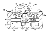
受台16には、被験者12の上腕28を載置させる平らな受面16aが形成されている。受台16には、その受面16aに矩形状に開口し、超音波センサ18の先端部の検出面18aがその開口内に位置するように超音波センサ18を収容する収容穴16bと、その収容穴16bの開口内周に設けられて液状物質30を収容し、超音波センサ18の検出面18aと受面16aに載置された上腕28の皮膚20との間に液状物質30を介在させる液状物質貯留装置32とが備えられている。液状物質30は、超音波の境界面における反射や散乱による減衰を抑制して超音波画像を明瞭とするための水や、カップリング剤としてよく知られた低粘性或いは流動性のゼリー等である。なお、超音波センサ18の検出面18aは上方を向いている。
A flat receiving
図2に示すように、外周部34aが収容穴16bの開口部内周縁に液密に固定され、且つ、内周部34bが超音波センサ18の検出面18aの周囲に固定された蛇腹状の弾性シート34を備え、液状物質30をその液状物質30の液面30aが検出面18aよりも上となるように弾性シート34上に貯留する液状物質貯留装置32が、収容穴16bの開口部に設けられている。
As shown in FIG. 2, the bellows-like elastic structure in which the outer
上腕28を受台16の受面16aに載置させることによって、超音波センサ18の検出面18aが液状物質30を介して上腕28の血管22を変形させない程度に軽く皮膚20に接触させることができる。
By placing the
図2に示すように、収容穴16b内に収容された超音波センサ18は、収容穴16b内に設けられた案内装置36によって上腕28の血管22に対して交差するX軸方向に案内され且つX軸方向駆動装置38により位置決めさせられる移動部材40により支持されている。
As shown in FIG. 2, the
案内装置36は、収容穴16bの内壁面に両端部が固定され、移動部材40をX軸方向に案内する長手状の案内部材42を備え、移動部材40には、X軸方向駆動装置38のねじ軸38aの外周面に形成された雄ねじと螺合する雌ねじが形成された部材44が固定されている。これによって、X軸方向駆動装置38のねじ軸38aが回転すると、移動部材40およびそれに固定された超音波センサ18がX軸方向に案内され且つ位置決めさせられる。
Both ends of the
図3は、血管超音波画像測定装置24の構成を説明する図である。この図3に示す超音波センサ18は、血管22に対して所定の超音波を発生させる超音波発振器及びその超音波に関して血管22から反射される反射波に基づいてその血管22に関連する生体情報すなわち血管状態(血管パラメータ)を検出する互いに平行な2列の第1短軸用超音波アレイ探触子A及び第2短軸用超音波アレイ探触子Bとそれらの長手方向中央部を連結する長軸用超音波アレイ探触子Cとを一平面すなわち平坦な検出面18a上に有して成るH型の超音波プローブ46と、その超音波プローブ46を位置決めするための多軸駆動装置(回動位置決め装置)48とを備えている。
FIG. 3 is a diagram illustrating the configuration of the vascular ultrasound
図4は、超音波プローブ46と血管22の関係を示す図であり、この図4に示すように、第1短軸用超音波アレイ探触子A、第2短軸用超音波アレイ探触子B、及び長軸用超音波アレイ探触子Cは、例えば圧電セラミックスから構成された複数個の超音波振動子(超音波発振子)a1〜anが直線的に配列されることにより長手状にそれぞれ構成されている。つまり、一対の第1短軸用超音波アレイ探触子Aおよび第2短軸用超音波アレイ探触子Bは、複数個の超音波振動子a1〜anがX軸方向に平行な方向に沿って直線的に配列され、長軸用超音波アレイ探触子Cは、複数個の超音波振動子a1〜anが一対の第1短軸用超音波アレイ探触子Aおよび第2短軸用超音波アレイ探触子Bの間にそれらと直交する方向に沿って直線的に配列されたものである。また、多軸駆動装置48は、図3に示すように、超音波プローブ46をX軸まわりに回動させてX軸まわりの回動位置を位置決めさせるX軸回動機構50と、超音波プローブ46を第1短軸用超音波アレイ探触子Aの長手方向の中央部を通り且つ検出面18aに垂直なZ軸まわりに回転させてZ軸まわりの回動位置を位置決めさせるZ軸回動機構52とを備えている。FIG. 4 is a diagram showing the relationship between the
図2に示すように、上腕28内には、上腕動脈E1および上腕骨H1等が存在している。上腕動脈E1である血管22は、図5に示すように、内膜L1、中膜L2、外膜L3から成る3層構造を備えている。この血管22に関して超音波を用いて得られる画像では、中膜L2からの反射がきわめて弱いため、内膜L1及び外膜L3が表示される。実際の画像では、血管22内及び中膜L2は黒く表示され、内膜L1及び外膜L3が白く表示され、組織が白黒の斑で表示される。この内膜L1は、外膜L3よりも大幅に厚みが薄く表示され、画像中において相対的に表示され難い一方で、FMDの評価に際してはその内膜L1の径の変化率を用いることが望まれる。As shown in FIG. 2, the brachial artery E <b> 1 and the humerus H <b> 1 exist in the
図3に戻って、血管超音波画像測定装置24は、所謂マイクロコンピュータから構成された電子制御装置54と、血管22の画像を表示する表示器56と、超音波駆動制御回路58と、駆動モータ制御回路60とを備えている。血管内皮機能検査装置10は、電子制御装置54によって統括的に制御されるものであり、その電子制御装置54によって超音波駆動制御回路58から駆動信号が供給されて超音波センサ18の超音波プローブ46の第1短軸用超音波アレイ探触子A、第2短軸用超音波アレイ探触子B、及び長軸用超音波アレイ探触子Cから超音波が放射される一方、その第1短軸用超音波アレイ探触子A、第2短軸用超音波アレイ探触子B、及び長軸用超音波アレイ探触子Cにより検知された超音波反射信号を受けてその超音波反射信号の処理が行われることによって、被験者12の皮膚20下の超音波画像が生成され表示器56に表示される。
Returning to FIG. 3, the blood vessel ultrasonic
電子制御装置54は、超音波駆動制御回路58を介して超音波センサ18による超音波の発生を制御する超音波駆動制御部62、その超音波センサ18により受信される反射波の検波処理を行う検波処理部64、その検波処理部64により検波された信号に関してドップラー信号処理を行うドップラー信号処理部66、Bモード信号処理を行うBモード信号処理部68、そのBモード信号処理部68により処理された信号に基づく画像を表示器56に表示させる表示制御を行う表示制御部70、駆動モータ制御回路60を介して多軸駆動装置48およびX軸方向駆動装置38の駆動を制御する3軸駆動モータ制御部72、及び加圧装置26の作動を制御する加圧制御部74等を制御機能として備えている。
The
表示器56は、図6に示すように、第1短軸用超音波アレイ探触子Aによる超音波画像を表示する第1短軸画像表示領域S1と、第2短軸用超音波アレイ探触子Bによる超音波画像を表示する第2短軸画像表示領域S2と、長軸用超音波アレイ探触子Cによる超音波画像を表示する長軸画像表示領域S3とを有している。更には、第1短軸画像表示領域S1、第2短軸画像表示領域S2、及び長軸画像表示領域S3は、皮膚20からの深さ寸法を示す共通の縦軸を備えたものである。また、前述したように、血管22の超音波画像が生成されるに際して、超音波プローブ46は対象となる血管22に対して所定の位置となるよう電子制御装置54(3軸駆動モータ制御部72)によって駆動モータ制御回路60から駆動信号を供給された多軸駆動装置48およびX軸方向駆動装置38が駆動することにより位置決めさせられる。上記所定の位置とは、第1短軸用超音波アレイ探触子A及び第2短軸用超音波アレイ探触子Bが対象となる血管22に対して直交する位置、且つ長軸用超音波アレイ探触子Cがその血管22に対して平行で真下となる位置である。この位置では、血管22が、長軸用超音波アレイ深触子Cの真上に位置し、且つ、第1短軸用超音波アレイ深触子A及び第2短軸用超音波アレイ深触子Bの長手方向中央部の真上に位置している。
As shown in FIG. 6, the
加圧装置26は、被験者12の上肢14における血管22の血流を阻止するために、血管超音波画像測定装置24による測定部位の上流側又は下流側(図1では下流側)の部位を圧迫するための装置であり、被験者12の前腕92に巻回されて用いられるカフ76と、そのカフ76のカフ圧を制御する血管超音波画像測定装置24に設けられた図示しないカフ圧制御装置とを、備えて構成されている。カフ76は、例えば空気圧等によりそのカフ圧が変更可能とされたものであり、上記カフ圧制御装置は、カフ76に連結された電動加圧ポンプ、電磁開放弁を備えた排気コック、及び圧力計等を備え、電子制御装置54(加圧制御部74)からの指令に従い超音波センサ18の駆動と連動して、上記加圧ポンプ及び上記排気コック等の作動を介して、カフ76のカフ圧を加圧乃至解放する制御を行う。
The pressurizing
血管内皮機能検査装置10による血管状態の測定に際して、超音波駆動制御回路58は、電子制御装置54からの指令に従って、例えば第1短軸用超音波アレイ探触子Aを構成する一列に配列された複数個の超音波振動子a1〜anのうち、その端の超音波振動子a1ら一定数の超音波振動子群例えば15個のa1〜a15毎に所定の位相差を付与しつつ10MHz程度の周波数で同時駆動するビームフォーミング駆動することにより超音波振動子の配列方向において収束性の超音波ビームを対象となる血管22に向かってすなわち上向きに向かって順次放射させ、超音波振動子を1個ずつずらしながらその超音波ビームをスキャン(走査)させたときの放射毎の反射波を受信して電子制御装置54へ入力させる。また、第1短軸用超音波アレイ探触子Aの放射面には、その超音波振動子a1〜anの配列方向に直交する方向に超音波ビームを収束させるための図示しない音響レンズが設けられている。上述のようなビームフォーミング駆動及び音響レンズによって収束させられた超音波ビームには、超音波振動子a1〜anの配列方向に対して直交する方向に長手状の収束断面が形成される。この収束断面の長手方向は、平面視において超音波振動子a1〜anの配列方向、及びビームの放射方向に対して、それぞれ直交する方向である。電子制御装置54(表示制御部70)は、上記反射波に基づいて画像を合成し、皮膚20下における血管22の横断面画像(短軸画像)、或いは縦断面画像(長軸画像)を生成させて、表示器56に表示させる。When the blood vessel state is measured by the vascular endothelial
以上のように構成された血管内皮機能検査装置10によれば、被験者12は、上腕28を受台16の受面16aに載置させることによって、超音波センサ18の検出面18aが液状物質30を介して皮膚20に接触する。そして、図2に示すように、被験者12の上腕28を受台16に載置させた状態にて測定された情報に基づいて図6に示す血管22の画像が表示器56に表示される。このようにして得られた血管画像から、図5に示す血管22の径或いは内皮の直径である内皮径(内腔径)が算出される。
According to the vascular endothelial
また、血管内皮機能検査装置10においては、対象となる血管22に関して安静状態における血管パラメータとその虚血状態からの充血後の血管パラメータとを比較することで、血管内皮機能の評価が行われる。すなわち、対象となる血管22に関して、先ず、被験者12の安静時における血管径dが測定された後、加圧装置26により測定部位における血管22の血流を阻止するためにその測定部位の上流側又は下流側の部位が圧迫された状態で所定時間維持させられ、その測定部位よりも上流側又は下流側の部位が虚血状態へ移行した段階でカフ76が急解放されて、対象となる血管22の虚血状態からの充血後の血管径(阻血解放後の最大血管径)dmaxが測定される。そして、虚血反応性充血後のFMD(血流依存性血管拡張反応)を表す血管径の変化率(%)[=100×(dmax−d)/d]が算出され、その結果に基づいて対象となる血管22の内皮機能が評価される。Moreover, in the vascular endothelial function test |
本実施例の血管内皮機能検査装置10によれば、上腕28が載置される受面16aを有する受台16と、受台16の受面16aに開口し、超音波センサ18の検出面18aがその開口内に位置するように超音波センサ18を収容する収容穴16bと、収容穴16bの開口内周に設けられて液状物質30を収容し、超音波センサ18の検出面18aと受面16aに載置された上腕28との間に液状物質30を介在させる液状物質貯留装置32とを含む。このため、上腕28を受台16の受面16aに載置させることによって、超音波センサ18の検出面18aがその上腕28の皮膚20に接触するので、上腕28を受台16に載置させた状態での血管径すなわち血管パラメータの測定が可能となる。これによって、従来のような超音波センサの検出面と受台の受面とに押さえられた状態で血管パラメータが測定されるものに比較して、血管内皮機能検査装置10は、上腕28を受台16の受面16aに載置させるだけであり、上腕28を容易に離すことができるので、血管パラメータの測定時の被験者12の不安を軽減させることができる。
According to the vascular endothelial
また、本実施例の血管内皮機能検査装置10によれば、収容穴16b内に収容された超音波センサ18は、収容穴16b内に設けられた案内装置36によって上腕28の動脈22に対して交差するX軸方向に案内され且つX軸方向駆動装置38により位置決めさせられる移動部材40に支持されている。このため、超音波センサ18のX軸方向駆動装置38によるX軸方向の位置決めが可能となり、上腕28内の血管22と超音波センサ18とのずれが自動的に解消される。
Further, according to the vascular endothelial
また、本実施例の血管内皮機能検査装置10によれば、液状物質貯留装置32は、外周部34aが収容穴16bの開口部内周縁に液密に固定され、且つ、内周部34bが超音波センサ18の検出面18aの周囲に液密に固定された弾性シート34を備え、液状物質30をその液状物質30の液面30aが超音波センサ18の検出面18aよりも上となるようにその弾性シート34上に貯留するものである。このため、測定時には、超音波センサ18の検出面18aと上腕28との間に液状物質30が液状物質貯留装置32により常時介在されているので、従来のようにゼリー(超音波ゼリー)が上腕28から流れ落ちることなく、良好な血管22の画像を連続的に得ることができる。
Further, according to the vascular endothelial
また、本実施例の血管内皮機能検査装置10によれば、超音波センサ18は、複数個の超音波振動子a1〜anがX軸方向に平行な方向に沿って直線的に配列された互いに平行な一対の第1短軸用超音波アレイ探触子Aおよび第2短軸用超音波アレイ探触子Bと、その一対の第1短軸用超音波アレイ探触子Aおよび第2短軸用超音波アレイ探触子Bの間にそれらと直交する方向に複数個の超音波振動子a1〜anが配置された長軸用超音波アレイ探触子Cとを検出面18aに備えた超音波プローブ46と、その超音波プローブ46をX軸まわりに回動させ、第1短軸用超音波アレイ探触子Aの長手方向の中央部を通り且つ検出面18aに垂直なZ軸まわりに回動させることが可能な回動位置決め装置48とを備えている。このため、超音波プローブ46をX軸および/またはZ軸まわりに回動させて血管22に対して超音波プローブ46を最適な位置へ自動的に位置決めすることができ、良好な血管22の画像を得ることができる。Further, according to the vascular endothelial
次に、本発明の他の実施例を説明する。なお、以下の説明において実施例相互間で共通する部分には同一の符号を付して説明を省略する。 Next, another embodiment of the present invention will be described. In the following description, portions common to the embodiments are denoted by the same reference numerals and description thereof is omitted.
本実施例の血管内皮機能検査装置78は、前述の実施例1の血管内皮機能検査装置10に比較して、受台16の収容穴16b内の構造が実施例1と異なる点で相違し、それ以外は略同様に構成されている。
The vascular endothelial
受台16の収容穴16b内には、図7に示すように、平板状の上板80aをX軸方向に移動させる粗動アクチュエータ80が収容されており、その上板80aには、超音波センサ18を収容する収容穴82aが形成された移動部材82が一体的に固定されている。なお、超音波センサ18の検出面18aが、実施例1の血管内皮機能検査装置10と同様に受台16の収容穴16bの開口内に位置するように、移動部材82および粗動アクチュエータ80が収容穴16b内に配設されている。また、粗動アクチュエータ80が駆動することによって、上板80aに固定された移動部材82すなわち超音波センサ18がX軸方向に移動する。
As shown in FIG. 7, a
図7に示すように、移動部材82には、その収容穴82aの開口内周に設けられて液状物質30を収容し、超音波センサ18の検出面18aと受面16aに載置された上腕28の皮膚20との間に液状物質30を介在させる実施例1と同様の液状物質貯留装置32が備えられている。また、収容穴82a内には、実施例1と同様の案内装置36が備えられており、超音波センサ18は、その案内装置36によってX軸方向に案内されX軸方向の位置が位置決めさせられる。なお、案内装置36に備えられたX軸方向駆動装置38は、超音波センサ18をX軸方向に移動させる移動速度が粗動アクチュエータ80よりも遅いものでありX軸方向の位置決め精度が高いものである。
As shown in FIG. 7, the moving
以上のように構成された血管内皮機能検査装置78によれば、実施例1の血管内皮機能検査装置10と同様に、上腕28を受台16の受面16aに載置させることによって、超音波センサ18の検出面18aが液状物質30を介して上腕28の血管22を変形させない程度に軽く皮膚20に接触する。このため、血管内皮機能検査装置78は、実施例1の血管内皮機能検査装置10と同様の効果を備えるものである。
According to the vascular endothelial
また、血管内皮機能検査装置78では、超音波センサ18をX軸方向の目標位置に位置決めする際に、3軸駆動モータ制御部72によって駆動モータ制御回路60を介して、例えば始めにX軸方向の移動速度が速い粗動アクチュエータ80を駆動させて前記目標位置の近くまで移動させ、その後X軸方向の位置決め精度が高いX軸方向駆動装置38を駆動させて前記目標位置に位置決めさせることができる。これによって、超音波センサ18のX軸方向に位置決めが好適に速くなり且つその位置決め精度が高くなる。
In the vascular endothelial
本実施例の血管内皮機能検査装置84は、前述の実施例1の血管内皮機能検査装置10に比較して、液状物質貯留装置86が実施例1の液状物質貯留装置32と異なる点で相違し、それ以外は略同様に構成されている。
The vascular endothelial
液状物質貯留装置86は、液状物質30が封入されて超音波センサ18の検出面18aと受面16aに載置された上腕28との間に介在された略円板形状の袋状弾性体88である。なお、液状物質30が封入された袋状弾性体88は、実施例1と同様の弾性シート34によって支持されている。
The liquid
本実施例の血管内皮機能検査装置84によれば、測定時には、超音波センサ18の検出面18aと上腕28との間に袋状弾性体88が常時介在されているので、従来のようにゼリー(超音波ゼリー)が上腕から流れ落ちることなく、良好な血管22の画像を連続的に得ることができる。
According to the vascular endothelial
本実施例の血管内皮機能検査装置90は、前述の実施例1の血管内皮機能検査装置10に比較して、被験者12の前腕92が受台16の載置されてその前腕92内の血管94の画像が表示器56に表示される点で相違し、それ以外は略同様に構成されている。なお、血管内皮機能検査装置90では、図9示すように、上腕28がカフ76によって圧迫された状態で所定時間維持させられ、その後、カフ76が急解放されて、トウ骨動脈E2の内皮機能が評価される。また、図10に示すように、前腕92は、トウ骨動脈E2、尺骨動脈E3、トウ骨H2、尺骨H3等を備えている。
Compared with the vascular endothelial
血管内皮機能検査装置90において、図10に示すように、被験者12は、前腕92を受台16の受面16aに載置させることによって、超音波センサ18の検出面18aが液状物質30を介して皮膚20に接触する。そして、被験者12の前腕92を受台16に載置させた状態で測定された情報に基づいて血管94の画像が表示器56に表示される。このようにして得られた血管94の画像から、たとえばトウ骨動脈E2の径或いは内皮の直径である内皮径(内腔径)が算出される。
In the vascular endothelial
本実施例の血管内皮機能検査装置90によれば、前腕92を受台16の受面16aに載置させることによって、超音波センサ18の検出面18aがその前腕92の皮膚20に接触するので、前腕92を受台16に載置させた状態での血管94の径すなわち血管パラメータの測定が可能となる。これによって、実施例1の血管内皮機能検査装置10と同様に、血管内皮機能検査装置90は、前腕92を受台16の受面16aに載置させるだけであり、前腕92を容易に離すことができるので、血管パラメータの測定時の被験者12の不安を軽減させることができる。
According to the vascular endothelial
以上、本発明の好適な実施例を図面に基づいて詳細に説明したが、本発明はこれに限定されるものではなく、更に別の態様においても実施される。 The preferred embodiments of the present invention have been described in detail with reference to the drawings. However, the present invention is not limited to these embodiments, and may be implemented in other modes.
例えば、前述の実施例において、上腕動脈E1(10)の測定を行う血管内皮機能検査装置10、78、84およびトウ骨動脈E2(94)の測定を行う血管内皮機能検査装置90に本発明が適用された例を説明したが、本発明はこれに限定されるものではなく、例えば上肢14の表皮面より測定できる動脈や静脈、或いはその他の下肢の血管等の血管パラメータの測定においても同様に適用され、効果を奏するものである。
For example, in the above-described embodiment, the present invention is applied to the vascular endothelial
また、前述の実施例において、前記超音波プローブ46は、互いに平行な2列の第1短軸用超音波アレイ探触子Aおよび第2短軸用超音波アレイ探触子Bとそれらの長手方向中央部を連結する長軸用超音波アレイ探触子Cとを検出面18aに有して成るH型のものを使用していたが、インライン型やその他のプローブを用いてもよい。
Further, in the above-described embodiment, the
また、前述の実施例において、血管内皮機能検査装置84では、弾性シート34が備えられていたが、取り外しても良い。
In the above-described embodiment, the vascular endothelial
その他一々例示はしないが、本発明は当業者の知識に基づいて種々の変更、改良を加えた態様で実施することができる。 Although not illustrated one by one, the present invention can be implemented in variously modified and improved modes based on the knowledge of those skilled in the art.
10、78、84、90:血管内皮機能検査装置(生体血管パラメータ測定装置)
16:受台
16a:受面
16b:収容穴
18:超音波センサ
18a:検出面
20:皮膚
22:血管
28:上腕(生体の一部)
30:液状物質
30a:液面
32:液状物質貯留装置
34:弾性シート
34a:外周部
34b:内周部
36:案内装置
38:X軸方向駆動装置
40:移動部材
46:超音波プローブ
48:多軸駆動装置(回動位置決め装置)
86:液状物質貯留装置
88:袋状弾性体
92:前腕(生体の一部)
94:血管
A:第1短軸用超音波アレイ探触子
B:第2短軸用超音波アレイ探触子
C:長軸用超音波アレイ探触子
a1〜an:複数個の超音波振動子(超音波発振子)10, 78, 84, 90: Vascular endothelial function testing device (biological blood vessel parameter measuring device)
16:
30:
86: Liquid substance storage device 88: Bag-like elastic body 92: Forearm (part of living body)
94: Vascular A: first short axis ultrasonic array probe B: second short axis ultrasonic array probe C: long ultrasonic array for axial probe a 1 ~a n: plural ultra Sound transducer (ultrasonic oscillator)
Claims (5)
前記生体の一部が載置される受面を有する受台と、
前記受台の受面に開口し、前記超音波センサの検出面が該開口内に位置するように該超音波センサを収容する収容穴と、
前記収容穴の開口内周に設けられて液状物質を収容し、前記超音波センサの検出面と前記受面に載置された前記生体の一部との間に該液状物質を介在させる液状物質貯留装置と
を、含むことを特徴とする生体血管パラメータ測定装置。 A biological blood vessel parameter measuring device for measuring a blood vessel parameter of a blood vessel in the skin by contacting an ultrasonic sensor on a part of the skin of the living body,
A cradle having a receiving surface on which a part of the living body is placed;
A receiving hole that opens to the receiving surface of the cradle and receives the ultrasonic sensor so that a detection surface of the ultrasonic sensor is located in the opening;
A liquid substance that is provided in the inner periphery of the opening of the accommodation hole, accommodates a liquid substance, and interposes the liquid substance between a detection surface of the ultrasonic sensor and a part of the living body placed on the receiving surface A biological blood vessel parameter measuring device comprising: a storage device.
複数個の超音波発振子が前記X軸方向に平行な方向に沿って直線的に配列された互いに平行な一対の第1短軸用超音波アレイ探触子および第2短軸用超音波アレイ探触子と、該一対の第1短軸用超音波アレイ探触子および第2短軸用超音波アレイ探触子の間にそれらと直交する方向に複数個の超音波発振子が配置された長軸用超音波アレイ探触子とを前記検出面に備えた超音波プローブと、
該超音波プローブを前記X軸まわりに回動させ、前記第1短軸用超音波アレイ探触子の長手方向の中央部を通り且つ前記検出面に垂直なZ軸まわりに回動させることが可能な回動位置決め装置とを備えていることを特徴とする請求項2の生体血管パラメータ測定装置。 The ultrasonic sensor is
A pair of first short-axis ultrasonic array probe and second short-axis ultrasonic array parallel to each other, in which a plurality of ultrasonic oscillators are linearly arranged along a direction parallel to the X-axis direction. A plurality of ultrasonic oscillators are arranged between the probe and the pair of first short-axis ultrasonic array probes and the second short-axis ultrasonic array probe in a direction perpendicular to them. An ultrasonic probe provided on the detection surface with a long-axis ultrasonic array probe;
The ultrasonic probe is rotated about the X axis, and is rotated about the Z axis that passes through the longitudinal center of the first short axis ultrasonic array probe and is perpendicular to the detection surface. The biological blood vessel parameter measuring device according to claim 2, further comprising a rotatable positioning device.
Applications Claiming Priority (1)
| Application Number | Priority Date | Filing Date | Title |
|---|---|---|---|
| PCT/JP2012/052190 WO2013114580A1 (en) | 2012-01-31 | 2012-01-31 | Biological vascular parameter measurement device |
Publications (2)
| Publication Number | Publication Date |
|---|---|
| JPWO2013114580A1 JPWO2013114580A1 (en) | 2015-05-11 |
| JP6013377B2 true JP6013377B2 (en) | 2016-10-25 |
Family
ID=48904658
Family Applications (1)
| Application Number | Title | Priority Date | Filing Date |
|---|---|---|---|
| JP2013556134A Active JP6013377B2 (en) | 2012-01-31 | 2012-01-31 | Biological blood vessel parameter measuring device |
Country Status (2)
| Country | Link |
|---|---|
| JP (1) | JP6013377B2 (en) |
| WO (1) | WO2013114580A1 (en) |
Family Cites Families (6)
| Publication number | Priority date | Publication date | Assignee | Title |
|---|---|---|---|---|
| JP2002238899A (en) * | 2001-02-14 | 2002-08-27 | Aloka Co Ltd | Ultrasonic probe scanning device |
| JP2002238898A (en) * | 2001-02-14 | 2002-08-27 | Aloka Co Ltd | Ultrasonic probe scanning device and ultrasonic diagnostic apparatus |
| JP2004305422A (en) * | 2003-04-07 | 2004-11-04 | Aloka Co Ltd | Somascope and ultrasonic probe driving system |
| JP5108432B2 (en) * | 2007-09-22 | 2012-12-26 | 株式会社ユネクス | Upper limb holding device for measuring biological blood vessel parameters |
| JP5277374B2 (en) * | 2009-03-10 | 2013-08-28 | 国立大学法人 名古屋工業大学 | In vivo lumen body evaluation device |
| US8845542B2 (en) * | 2009-09-09 | 2014-09-30 | Unex Corporation | Blood vessel function inspecting apparatus |
-
2012
- 2012-01-31 WO PCT/JP2012/052190 patent/WO2013114580A1/en active Application Filing
- 2012-01-31 JP JP2013556134A patent/JP6013377B2/en active Active
Also Published As
| Publication number | Publication date |
|---|---|
| JPWO2013114580A1 (en) | 2015-05-11 |
| WO2013114580A1 (en) | 2013-08-08 |
Similar Documents
| Publication | Publication Date | Title |
|---|---|---|
| JP5411272B2 (en) | Ultrasound angiography equipment | |
| JP5219228B2 (en) | Vascular function testing device | |
| US10172527B2 (en) | Method and apparatus for measuring a physical parameter in mammal soft tissues by propagating shear waves | |
| JP5499939B2 (en) | Measuring device, biopsy device, flow velocity measuring method, and pressure measuring method | |
| JP5474986B2 (en) | Vascular function testing device | |
| JP5224221B2 (en) | Vascular function testing device | |
| JP5474966B2 (en) | Biological blood vessel state measurement device | |
| JP5998197B2 (en) | Biological blood vessel diameter continuous measurement device | |
| JP2018023610A (en) | Ultrasonic measurement apparatus and control method | |
| JP2007195662A (en) | Apparatus for measuring intraluminal diameter of biological tubular body | |
| WO2017204176A1 (en) | Ultrasonic cross-sectional image measurement apparatus | |
| JP5527953B2 (en) | Vasodilation reaction image display device | |
| JP2005074146A (en) | Method for measuring ultrasonic wave, and mechanism for generating the ultrasonic wave | |
| JP5896759B2 (en) | Biological arterial endothelial function measuring device | |
| JP6013377B2 (en) | Biological blood vessel parameter measuring device | |
| JP6671065B2 (en) | Vascular endothelial function measurement device for brachial artery | |
| JP2017070317A (en) | Ultrasound diagnostic device and pulse wave measurement method | |
| JP6243719B2 (en) | Biological blood vessel state measurement device | |
| Beyaz | An acoustic blood pressure sensing scheme using time of flight and shear wave elastography techniques | |
| JP6192490B2 (en) | Biological blood vessel state measurement device | |
| JP5723960B2 (en) | Vascular function testing device | |
| JP2755964B2 (en) | Ultrasonic probe | |
| JPH0492650A (en) | Ultrasonic diagnostic device | |
| Trawiński et al. | Ultrasonic Non-Invasive Method for Relative Changes Measurements of Intima-Media Thickness in Artery Walls |
Legal Events
| Date | Code | Title | Description |
|---|---|---|---|
| A131 | Notification of reasons for refusal |
Free format text: JAPANESE INTERMEDIATE CODE: A131 Effective date: 20160119 |
|
| A521 | Request for written amendment filed |
Free format text: JAPANESE INTERMEDIATE CODE: A523 Effective date: 20160316 |
|
| TRDD | Decision of grant or rejection written | ||
| A01 | Written decision to grant a patent or to grant a registration (utility model) |
Free format text: JAPANESE INTERMEDIATE CODE: A01 Effective date: 20160830 |
|
| A61 | First payment of annual fees (during grant procedure) |
Free format text: JAPANESE INTERMEDIATE CODE: A61 Effective date: 20160921 |
|
| R150 | Certificate of patent or registration of utility model |
Ref document number: 6013377 Country of ref document: JP Free format text: JAPANESE INTERMEDIATE CODE: R150 |
|
| R250 | Receipt of annual fees |
Free format text: JAPANESE INTERMEDIATE CODE: R250 |
|
| R250 | Receipt of annual fees |
Free format text: JAPANESE INTERMEDIATE CODE: R250 |
|
| R250 | Receipt of annual fees |
Free format text: JAPANESE INTERMEDIATE CODE: R250 |
|
| R250 | Receipt of annual fees |
Free format text: JAPANESE INTERMEDIATE CODE: R250 |
|
| R250 | Receipt of annual fees |
Free format text: JAPANESE INTERMEDIATE CODE: R250 |