JP6013161B2 - Magnetic resonance imaging apparatus and magnetic resonance imaging method - Google Patents
Magnetic resonance imaging apparatus and magnetic resonance imaging method Download PDFInfo
- Publication number
- JP6013161B2 JP6013161B2 JP2012266944A JP2012266944A JP6013161B2 JP 6013161 B2 JP6013161 B2 JP 6013161B2 JP 2012266944 A JP2012266944 A JP 2012266944A JP 2012266944 A JP2012266944 A JP 2012266944A JP 6013161 B2 JP6013161 B2 JP 6013161B2
- Authority
- JP
- Japan
- Prior art keywords
- frequency
- magnetic resonance
- image
- phase
- magnetic field
- Prior art date
- Legal status (The legal status is an assumption and is not a legal conclusion. Google has not performed a legal analysis and makes no representation as to the accuracy of the status listed.)
- Active
Links
Images


Classifications
-
- G—PHYSICS
- G01—MEASURING; TESTING
- G01R—MEASURING ELECTRIC VARIABLES; MEASURING MAGNETIC VARIABLES
- G01R33/00—Arrangements or instruments for measuring magnetic variables
- G01R33/20—Arrangements or instruments for measuring magnetic variables involving magnetic resonance
- G01R33/44—Arrangements or instruments for measuring magnetic variables involving magnetic resonance using nuclear magnetic resonance [NMR]
- G01R33/48—NMR imaging systems
- G01R33/54—Signal processing systems, e.g. using pulse sequences ; Generation or control of pulse sequences; Operator console
- G01R33/56—Image enhancement or correction, e.g. subtraction or averaging techniques, e.g. improvement of signal-to-noise ratio and resolution
- G01R33/565—Correction of image distortions, e.g. due to magnetic field inhomogeneities
-
- A—HUMAN NECESSITIES
- A61—MEDICAL OR VETERINARY SCIENCE; HYGIENE
- A61B—DIAGNOSIS; SURGERY; IDENTIFICATION
- A61B5/00—Measuring for diagnostic purposes; Identification of persons
- A61B5/05—Detecting, measuring or recording for diagnosis by means of electric currents or magnetic fields; Measuring using microwaves or radio waves
- A61B5/055—Detecting, measuring or recording for diagnosis by means of electric currents or magnetic fields; Measuring using microwaves or radio waves involving electronic [EMR] or nuclear [NMR] magnetic resonance, e.g. magnetic resonance imaging
-
- A—HUMAN NECESSITIES
- A61—MEDICAL OR VETERINARY SCIENCE; HYGIENE
- A61B—DIAGNOSIS; SURGERY; IDENTIFICATION
- A61B5/00—Measuring for diagnostic purposes; Identification of persons
- A61B5/0033—Features or image-related aspects of imaging apparatus classified in A61B5/00, e.g. for MRI, optical tomography or impedance tomography apparatus; arrangements of imaging apparatus in a room
- A61B5/0037—Performing a preliminary scan, e.g. a prescan for identifying a region of interest
-
- A—HUMAN NECESSITIES
- A61—MEDICAL OR VETERINARY SCIENCE; HYGIENE
- A61B—DIAGNOSIS; SURGERY; IDENTIFICATION
- A61B5/00—Measuring for diagnostic purposes; Identification of persons
- A61B5/72—Signal processing specially adapted for physiological signals or for diagnostic purposes
- A61B5/7203—Signal processing specially adapted for physiological signals or for diagnostic purposes for noise prevention, reduction or removal
-
- G—PHYSICS
- G01—MEASURING; TESTING
- G01R—MEASURING ELECTRIC VARIABLES; MEASURING MAGNETIC VARIABLES
- G01R33/00—Arrangements or instruments for measuring magnetic variables
- G01R33/20—Arrangements or instruments for measuring magnetic variables involving magnetic resonance
- G01R33/28—Details of apparatus provided for in groups G01R33/44 - G01R33/64
- G01R33/38—Systems for generation, homogenisation or stabilisation of the main or gradient magnetic field
- G01R33/385—Systems for generation, homogenisation or stabilisation of the main or gradient magnetic field using gradient magnetic field coils
-
- G—PHYSICS
- G01—MEASURING; TESTING
- G01R—MEASURING ELECTRIC VARIABLES; MEASURING MAGNETIC VARIABLES
- G01R33/00—Arrangements or instruments for measuring magnetic variables
- G01R33/20—Arrangements or instruments for measuring magnetic variables involving magnetic resonance
- G01R33/28—Details of apparatus provided for in groups G01R33/44 - G01R33/64
- G01R33/38—Systems for generation, homogenisation or stabilisation of the main or gradient magnetic field
- G01R33/387—Compensation of inhomogeneities
-
- G—PHYSICS
- G01—MEASURING; TESTING
- G01R—MEASURING ELECTRIC VARIABLES; MEASURING MAGNETIC VARIABLES
- G01R33/00—Arrangements or instruments for measuring magnetic variables
- G01R33/20—Arrangements or instruments for measuring magnetic variables involving magnetic resonance
- G01R33/44—Arrangements or instruments for measuring magnetic variables involving magnetic resonance using nuclear magnetic resonance [NMR]
- G01R33/48—NMR imaging systems
- G01R33/54—Signal processing systems, e.g. using pulse sequences ; Generation or control of pulse sequences; Operator console
- G01R33/543—Control of the operation of the MR system, e.g. setting of acquisition parameters prior to or during MR data acquisition, dynamic shimming, use of one or more scout images for scan plane prescription
-
- G—PHYSICS
- G01—MEASURING; TESTING
- G01R—MEASURING ELECTRIC VARIABLES; MEASURING MAGNETIC VARIABLES
- G01R33/00—Arrangements or instruments for measuring magnetic variables
- G01R33/20—Arrangements or instruments for measuring magnetic variables involving magnetic resonance
- G01R33/44—Arrangements or instruments for measuring magnetic variables involving magnetic resonance using nuclear magnetic resonance [NMR]
- G01R33/48—NMR imaging systems
- G01R33/54—Signal processing systems, e.g. using pulse sequences ; Generation or control of pulse sequences; Operator console
- G01R33/56—Image enhancement or correction, e.g. subtraction or averaging techniques, e.g. improvement of signal-to-noise ratio and resolution
- G01R33/565—Correction of image distortions, e.g. due to magnetic field inhomogeneities
- G01R33/56563—Correction of image distortions, e.g. due to magnetic field inhomogeneities caused by a distortion of the main magnetic field B0, e.g. temporal variation of the magnitude or spatial inhomogeneity of B0
-
- G—PHYSICS
- G06—COMPUTING; CALCULATING OR COUNTING
- G06T—IMAGE DATA PROCESSING OR GENERATION, IN GENERAL
- G06T11/00—2D [Two Dimensional] image generation
- G06T11/003—Reconstruction from projections, e.g. tomography
- G06T11/005—Specific pre-processing for tomographic reconstruction, e.g. calibration, source positioning, rebinning, scatter correction, retrospective gating
-
- G—PHYSICS
- G01—MEASURING; TESTING
- G01R—MEASURING ELECTRIC VARIABLES; MEASURING MAGNETIC VARIABLES
- G01R33/00—Arrangements or instruments for measuring magnetic variables
- G01R33/20—Arrangements or instruments for measuring magnetic variables involving magnetic resonance
- G01R33/44—Arrangements or instruments for measuring magnetic variables involving magnetic resonance using nuclear magnetic resonance [NMR]
- G01R33/48—NMR imaging systems
- G01R33/54—Signal processing systems, e.g. using pulse sequences ; Generation or control of pulse sequences; Operator console
- G01R33/56—Image enhancement or correction, e.g. subtraction or averaging techniques, e.g. improvement of signal-to-noise ratio and resolution
- G01R33/5608—Data processing and visualization specially adapted for MR, e.g. for feature analysis and pattern recognition on the basis of measured MR data, segmentation of measured MR data, edge contour detection on the basis of measured MR data, for enhancing measured MR data in terms of signal-to-noise ratio by means of noise filtering or apodization, for enhancing measured MR data in terms of resolution by means for deblurring, windowing, zero filling, or generation of gray-scaled images, colour-coded images or images displaying vectors instead of pixels
Description
本発明は、磁気共鳴イメージング(以下、MRIと呼ぶ)装置に係り、特に静磁場不均一に起因するアーチファクトを補正する手段を備えたMRI装置に関する。 The present invention relates to a magnetic resonance imaging (hereinafter referred to as MRI) apparatus, and more particularly to an MRI apparatus provided with means for correcting artifacts caused by static magnetic field inhomogeneity.
MRI装置は、静磁場に置かれた被検体に高周波磁場、傾斜磁場を印加し、核磁気共鳴により被検体から発生する信号を計測し、画像化する医用画像診断装置である。MRI装置では、一般に撮像面を特定するスライス傾斜磁場を印加すると同時にその面内の磁化を励起させる励起パルス(高周波磁場パルス)を与え、これにより励起された磁化が収束する段階で発生する核磁気共鳴信号(エコー)を取得する。このとき、磁化に位置情報を与えるため、励起からエコーを得るまでの間に、撮像面内で互いに垂直な方向の位相エンコード傾斜磁場とリードアウト傾斜磁場とを印加する。計測されたエコーは、横軸をkx、縦軸をkyとするk空間に配置され、k空間のエコーに逆フーリエ変換を施すことによって画像再構成が行われる。 An MRI apparatus is a medical image diagnostic apparatus that applies a high-frequency magnetic field and a gradient magnetic field to a subject placed in a static magnetic field, measures a signal generated from the subject by nuclear magnetic resonance, and forms an image. In an MRI apparatus, a nuclear magnetic field is generally generated when an excitation pulse (a high-frequency magnetic field pulse) that excites the magnetization in the surface is applied at the same time as applying a slice gradient magnetic field that specifies the imaging surface, and the excited magnetization converges by this. Resonance signal (echo) is acquired. At this time, in order to give positional information to the magnetization, a phase encoding gradient magnetic field and a readout gradient magnetic field in directions perpendicular to each other in the imaging surface are applied between the excitation and the echo acquisition. The measured echoes are arranged in a k-space where the horizontal axis is kx and the vertical axis is ky, and image reconstruction is performed by performing inverse Fourier transform on the echoes in the k-space.
再構成画像の画素値は、絶対値情報と位相情報を含む複素数である。この絶対値と位相は、撮像シーケンスの種類、画素サイズや繰り返し時間などからなる撮像パラメータや、被検体内における磁化の密度や緩和時間、共鳴周波数の空間分布などによって決まる。通常の再構成画像として、絶対値を画素値とする濃淡画像が用いられることが多いが、絶対値と位相とを組み合わせて1つの画像を生成する手法も知られている。例えば、特許文献1では、再構成画像の各画素の位相を、閾値を[-π,π]とする値に変換して位相画像を生成し、さらに位相画像の閾値を[0,1]に変換した位相マスクを作成し、位相マスクの各画素の位相をq乗(q≧1)した値と、同画素の絶対値との積を求め、求めた積を画素値とする画像を生成することが開示されている。qの値は、コントラスト-ノイズ比が最大になるように決定される。このような処理によって高コントラストの画像を得ることができる。
The pixel value of the reconstructed image is a complex number including absolute value information and phase information. The absolute value and phase are determined by imaging parameters including the type of imaging sequence, pixel size, repetition time, etc., magnetization density and relaxation time in the subject, and spatial distribution of resonance frequencies. As a normal reconstructed image, a grayscale image having an absolute value as a pixel value is often used. However, a method of generating one image by combining an absolute value and a phase is also known. For example, in
一方、特許文献2は、エコーの位相値に静磁場強度の情報が反映されることを利用して、エコータイムをΔtずらした2つの位相分布画像から静磁場強度分布を求めることを開示している。この静磁場強度分布を用いてシミングを行う。
On the other hand,
また、非特許文献1には、ゼロエンコードで取得したエコー信号を用いてk空間のエコー信号の位相補正を行うことが開示されている。また、k空間上のエコーにハイパスフィルタ処理やローパスフィルタ処理を施すことにより静磁場不均一に起因する位相情報を除去する処理も知られている。
Non-Patent
(実施例1から実施例4)
MRIの静磁場発生装置が発生する静磁場に不均一がある場合、被検体の磁化が本来受けるべき位相回転以上の回転を受け、画像上にアーチファクトとして表れる。そのため、特許文献2のようにシムコイル等を用いて静磁場不均一を補正する方法があるが、完全に静磁場不均一を補正することは難しい。
(Example 1 to Example 4)
When the static magnetic field generated by the MRI static magnetic field generator is non-uniform, the magnetization of the subject undergoes rotation more than the phase rotation that should be received, and appears as an artifact on the image. Therefore, there is a method of correcting static magnetic field nonuniformity using a shim coil or the like as in
また、非特許文献1に開示されているゼロエンコードのエコーを用いてk空間のエコーの位相補正を行う方法は、静磁場不均一に起因する位相情報のみを補正することはできない。
Further, the method of performing phase correction of k-space echoes using zero-encoded echoes disclosed in Non-Patent
また、k空間上のエコーにハイパスフィルタ処理やローパスフィルタ処理を施すことにより静磁場不均一に起因する位相情報を除去する処理も知られているが、画像上にアーチファクトが残留することや、静磁場不均一に起因する位相情報以外の重要な位相情報まで除去することがある。 In addition, processing for removing phase information caused by static magnetic field inhomogeneity by applying high-pass filtering or low-pass filtering to echoes in k-space is also known, but artifacts may remain on the image, Even important phase information other than phase information due to magnetic field inhomogeneity may be removed.
本発明は、上記課題に鑑みてなされたもので、核磁気共鳴信号に含まれる、静磁場不均一に起因する大域的な位相変化を除去する技術を提供することを目的とする。 The present invention has been made in view of the above problems, and an object thereof is to provide a technique for removing a global phase change caused by static magnetic field inhomogeneity included in a nuclear magnetic resonance signal.
本発明は、静磁場不均一に起因して核磁気共鳴信号に生じる位相成分が、所定の周波数帯域であることに着目し、静磁場不均一に起因する周波数帯域の位相成分を、本撮像の核磁気共鳴信号から生成した画像から除去する。静磁場不均一に起因する位相成分の所定の周波数帯域は、予備撮像により取得した核磁気共鳴信号から求める。 The present invention pays attention to the fact that the phase component generated in the nuclear magnetic resonance signal due to the static magnetic field inhomogeneity is in a predetermined frequency band, and the phase component in the frequency band due to the static magnetic field inhomogeneity is Remove from image generated from nuclear magnetic resonance signal. The predetermined frequency band of the phase component caused by the static magnetic field inhomogeneity is obtained from the nuclear magnetic resonance signal acquired by the preliminary imaging.
本発明によれば、予備撮像で得た核磁気共鳴信号から静磁場不均一に起因する位相成分の周波数範囲を求めることができるため、本撮像により取得した核磁気共鳴信号に対する信号処理により、静磁場不均一に起因する位相成分を除去することが可能である。よって、静磁場強度、撮像シーケンス、撮像パラメータ、被検体内における磁化の密度や緩和時間などの要因や、本撮像の撮像方法に関わらず、静磁場不均一によるアーチファクトを低減できる。 According to the present invention, since the frequency range of the phase component resulting from the static magnetic field inhomogeneity can be obtained from the nuclear magnetic resonance signal obtained by the preliminary imaging, the signal processing on the nuclear magnetic resonance signal obtained by the main imaging can be performed. It is possible to remove a phase component caused by magnetic field inhomogeneity. Therefore, regardless of factors such as static magnetic field strength, imaging sequence, imaging parameters, magnetization density and relaxation time in the subject, and imaging methods of the main imaging, artifacts due to static magnetic field inhomogeneity can be reduced.
本発明は、核磁気共鳴信号に含まれる、静磁場不均一に起因する磁化の位相回転による信号成分(位相成分)が、所定の周波数帯域(具体的には、低周波帯域)として表れることに着目し、静磁場不均一に起因する位相成分を、本撮像で取得した核磁気共鳴信号、および、本撮像で取得した核磁気共鳴信号から再構成した画像の少なくとも一方から除去する。予備撮像により取得した核磁気共鳴信号から静磁場不均一により生じた位相情報を取得し、静磁場不均一に起因する所定の周波数帯域(低周波帯域)の範囲を割り出す。これにより、所望の本撮像で得る画像において、静磁場不均一に起因する位相成分によるアーチファクトの低減を実現する。以下、本発明の実施形態を具体的に説明する。 In the present invention, a signal component (phase component) due to phase rotation of magnetization caused by non-uniform magnetic field included in a nuclear magnetic resonance signal appears as a predetermined frequency band (specifically, a low frequency band). Attention is paid to removing the phase component caused by the static magnetic field inhomogeneity from at least one of the nuclear magnetic resonance signal acquired by the main imaging and the image reconstructed from the nuclear magnetic resonance signal acquired by the main imaging. Phase information generated by the static magnetic field inhomogeneity is acquired from the nuclear magnetic resonance signal acquired by the preliminary imaging, and a range of a predetermined frequency band (low frequency band) caused by the static magnetic field inhomogeneity is determined. This realizes reduction of artifacts due to phase components caused by non-uniform static magnetic fields in an image obtained by desired actual imaging. Hereinafter, embodiments of the present invention will be specifically described.
本実施形態のMRI装置の構成について図1および図2を用いて説明する。図1のように、MRI装置は、静磁場の中に置かれた被検体103に高周波磁場および傾斜磁場を印加して、被検体103から発生する核磁気共鳴信号を検出する撮像部10と、撮像部10の動作を制御する制御部11と、核磁気共鳴信号に対して演算を行い、画像を生成する画像処理部12とを備えている。制御部11は、所定の予備撮像と本撮像とを撮像部10に実行させる。図2に示すように、画像処理部12は、予備撮像により取得した核磁気共鳴信号から、静磁場の不均一に起因する位相成分の周波数帯域を求める周波数帯域算出部202と、本撮像により取得された核磁気共鳴信号から生成した画像から周波数帯域の位相成分を除去するための静磁場不均一除去部203とを含む。以下、さらに説明する。
The configuration of the MRI apparatus of this embodiment will be described with reference to FIGS. As shown in FIG. 1, the MRI apparatus applies a high-frequency magnetic field and a gradient magnetic field to a
撮像部10は、図1のように、被検体103が配置される撮像空間に均一な静磁場を発生するマグネット101と、撮像空間に傾斜磁場を発生する傾斜磁場コイル102と、撮像空間に高周波磁場を照射するとともに核磁気共鳴信号(以下、エコーと呼ぶ)を検出するプローブ107と、傾斜磁場コイル102に電流を供給する傾斜磁場電源105と、プローブ107に高周波電圧を供給する高周波発生装置106と、プローブ107の検出したエコーを検波する受信器108と、シーケンサ104とを備えている。被検体(例えば生体)103は、寝台(テーブル)等に載置され、撮像空間に配置される。
As shown in FIG. 1, the
シーケンサ104は、制御部11によってその動作が制御され、所定の撮像方法および撮像条件による撮像を実行する。具体的には、シーケンサ104は、傾斜磁場電源105と高周波発生装置106とに、所定の撮像方法を実現するタイミングでそれぞれ命令を送り、電流・電圧信号を発生させ、傾斜磁場コイル102およびプローブ107にそれぞれ供給させる。傾斜磁場コイル102は傾斜磁場を、プローブ107は高周波磁場を、それぞれ発生し、被検体103に印加する。被検体103から発生したエコーはプローブ107によって受波され、受信器108で検波される。受信器108の検波の基準となる核磁気共鳴周波数(検波基準周波数f0)は、シーケンサ104によりセットされる。検波された信号は、計算機109に送られる。
The operation of the
シーケンサ104は、予めプログラムされたタイミング、強度で各部が動作するように制御を行う。プログラムのうち、特に、高周波磁場、傾斜磁場および信号受信のタイミングや強度を記述したものはパルスシーケンスと呼ばれる。パルスシーケンスは、撮像の目的に応じて種々のものが知られている。制御部11は、シーケンサ104にパルスシーケンスの種類の選択の指示や、上記タイミングや強度の設定を行う。これにより、所定の撮像方法で撮像が実行されるように制御する。
The
制御部11および画像処理部12は、計算機109内に配置される。計算機109内のCPUが内蔵されている不図示のメモリに格納されているプログラムを読み込んで実行することにより、制御部11および画像処理部12の機能をそれぞれ実現する。
The
また、画像処理部12内には、図2のように、周波数帯域算出部202および静磁場不均一除去部203の他に、受信器108が検波したエコーをk空間に配置するエコー計測部201と、k空間に配置されたデータから画像を再構成する画像再構成部204と、得られた画像を表示装置110に表示させる画像表示部205とが備えられている。これらの各部についても、計算機109内のCPUが予め格納されたプログラムを読み込んで実行することによりそれぞれ実現する。
Further, in the
計算機109には、表示装置110と記憶媒体111が接続され、画像処理により得た画像等が表示される。検波された信号や計測条件を必要に応じて記憶媒体111に記憶させてもよい。
A
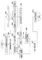
次に、本実施形態の撮像処理の流れを図3のフローチャートを用いて説明する。
制御部11は、予め定めた予備撮像のシーケンスを撮像部10に実行させる(S301)。予備撮像シーケンスは、所定部位を画像化するための核磁気共鳴信号(エコー)をエコータイム(TE)を所定時間(Δt)ずらして2組取得するものである。例えば、エコータイムをT0に設定して位相エンコード量を変更しながら、画像生成に必要な所定数のエコーを取得する計測と、エコータイムをT0+Δt(Δt≠0)に設定して同様に所定の数のエコーを取得する計測とを行う予備撮像シーケンスを行う。2回の計測の撮影条件は、エコータイム以外は、同一条件であることが望ましい。また、予備撮像は、被検体103を撮像空間に配置した状態で行うことが望ましい。
Next, the flow of the imaging process of the present embodiment will be described using the flowchart of FIG.
The
予備撮像シーケンスは、エコータイムをΔtずらす他は、通常の撮像シーケンス(スピンエコーシーケンスやグラディエントエコーシーケンス等)と同様に行う。また、公知の静磁場強度分布を算出するための撮像シーケンス(例えば、特許文献2(図1)に開示されているシーケンス)を用いることも可能である。 The preliminary imaging sequence is performed in the same manner as a normal imaging sequence (such as a spin echo sequence or a gradient echo sequence) except that the echo time is shifted by Δt. It is also possible to use a known imaging sequence (for example, a sequence disclosed in Patent Document 2 (FIG. 1)) for calculating a static magnetic field strength distribution.
予備撮像シーケンスの2回の計測で受信器108が検波して得られた2組のエコーは、画像処理部12のエコー計測部201において、k空間に配置されるとともに、k空間上の同一位置同士で信号値の差分を求められる。2組のエコーは、静磁場強度の不均一を感受した時間に比例した位相情報と他の条件による位相情報が付与されているため、両エコーの差分を求めることにより、静磁場不均一以外の要素による位相情報を低減したエコーを得ることができる。差分により得られたエコーを以下、予備撮像エコー501と呼ぶ。
予備撮像エコーは、複素数である。
Two sets of echoes obtained by detection by the
The preliminary imaging echo is a complex number.
画像処理部12の周波数帯域算出部202は、予備撮像エコー501から、静磁場の不均一に起因する位相成分の周波数帯域を求める(図3のS302)。S302の処理を図4のフローおよび図5のデータの流れを示す説明図を用いて詳しく説明する。周波数帯域算出部202内の位相画像生成部21は、k空間に配置された予備撮像エコー501に対して逆フーリエ変換(FT)を行う(図4のS401)。これにより、図5のように、予備撮像エコー501から実部画像502および虚部画像503が得られる。位相画像生成部21は、実部画像502と虚部画像503から各画素の位相値を算出し、位相画像504を生成する(S402)。この位相画像は、予備撮像で得た2組のエコーの位相差の分布を実空間で示しており、静磁場強度の不均一を反映している。
The frequency
周波数帯域算出部202の閾値周波数算出部22は、位相画像504から静磁場の不均一に起因する位相成分の周波数帯域505を求める(図5)。まず、閾値周波数算出部22は、位相画像504をフーリエ変換し、フーリエ変換後のデータ(位相データ)を得る(図4のS403)。静磁場不均一に起因する位相成分が低周波に現れることを利用して、この位相データの周波数分布から静磁場不均一に起因する位相データの周波数帯域を算出する。具体的には、位相データの周波数分布に基づいて高周波位相データと低周波位相データとに分離する閾値周波数を求める。位相データの閾値周波数以下の周波数帯域を、静磁場不均一に起因する位相成分の周波数帯域とする(S404,405)。
The threshold
周波数分布に基づいて閾値周波数を求める処理としては各種の方法を用いることができる。一例としては、位相データの周波数分布のヒストグラムに対して、判別分析法、加重平均、加算平均、および、p-tile(Pタイル)法等のうち少なくとも一つの処理を施すことにより、ヒストグラムの中心を求め、これを閾値周波数とすることができる。 Various methods can be used as processing for obtaining the threshold frequency based on the frequency distribution. For example, the histogram of the frequency distribution of the phase data is subjected to at least one of a discriminant analysis method, a weighted average, an addition average, a p-tile (P tile) method, etc. And this can be used as a threshold frequency.
次に、制御部11は、操作者が設定した所望の本撮像シーケンスを撮像部10に実行させ、本撮像による核磁気共鳴信号(本撮像エコー507)を取得する(図3のS303)。なお、本撮像シーケンスの実行は、このタイミングでなくてもよく、本撮像をこれ以前のタイミングで行って、取得した本撮像エコー507を記憶媒体111に格納しておき、これを記憶媒体111から読み出して用いてもよい。
Next, the
静磁場不均一除去部203および画像再構成部204は、S302で求めた静磁場の不均一に起因する位相成分の周波数帯域と、S303で得た本撮像エコー507と、を用いて、静磁場不均一による位相成分を除去した再構成画像を生成する(S304)。除去の手法としては、本撮像エコー507から、静磁場不均一に起因する位相成分の周波数帯域を除去して静磁場不均一除去後エコー508を得て、このエコー508から静磁場不均一除去後画像509を再構成する手法(k空間上での処理)がある。また、本撮像エコー507から画像を再構成し、再構成画像から静磁場不均一に起因する位相成分を除去することにより、静磁場不均一除去後画像509を得る手法(画像空間上での処理)を用いることも可能である。いずれの場合も、上記周波数帯域の位相成分を除去するフィルタ506を生成し、フィルタを適用することによりエコーや再構成画像から上記周波数帯域の位相成分を除去する手法を用いることができる。具体的な処理の例については、後の実施例で説明する。
The static magnetic field
静磁場不均一に起因する位相成分が除去された再構成画像は、画像処理部12の画像表示部205によって表示装置110に表示される(図3のS305)。
The reconstructed image from which the phase component due to the static magnetic field inhomogeneity has been removed is displayed on the
以上説明したように、本実施形態によれば、予備撮像により静磁場不均一に起因する位相成分の周波数範囲を求めることができるため、本撮像を行う撮像空間の静磁場不均一の周波数帯域を求めることができる。これにより、本撮像により取得した核磁気共鳴処理に対する信号処理により、静磁場不均一に起因する位相成分を除去することができるため、画像診断における重要な位相情報が表れる局所的な高周波の位相成分から、静磁場不均一に起因する低周波位相成分を分離できる。 As described above, according to the present embodiment, since the frequency range of the phase component caused by the static magnetic field inhomogeneity can be obtained by preliminary imaging, the frequency band of the static magnetic field inhomogeneity of the imaging space in which the main imaging is performed is set. Can be sought. As a result, the phase component caused by the static magnetic field inhomogeneity can be removed by the signal processing for the nuclear magnetic resonance processing acquired by the main imaging, so that the local high-frequency phase component in which important phase information appears in the image diagnosis appears. Therefore, it is possible to separate the low-frequency phase component caused by the static magnetic field inhomogeneity.
また、予備撮像により静磁場不均一に起因する位相成分の周波数帯域を求めることにより、静磁場強度、撮像シーケンス、撮像パラメータ、被検体内における磁化の密度や緩和時間などの要因や、本撮像の撮像方法の影響に依らず、静磁場不均一によるアーチファクトを除去することが可能である。このため、固定の周波数帯域のフィルタ処理で静磁場不均一に起因する位相成分を除去する場合と比較して、低周波の位相が残留しにくく、画像上にアーチファクトをより低減できる。 Also, by obtaining the frequency band of the phase component due to static magnetic field inhomogeneity by preliminary imaging, factors such as static magnetic field strength, imaging sequence, imaging parameters, magnetization density and relaxation time in the subject, Regardless of the influence of the imaging method, it is possible to remove artifacts due to non-uniform static magnetic fields. For this reason, compared with the case where the phase component resulting from static magnetic field inhomogeneity is removed by filtering processing in a fixed frequency band, the low frequency phase hardly remains, and the artifacts can be further reduced on the image.
以下、上述の図2の周波数帯域算出部202による周波数帯域算出処理(S302)、ならびに、静磁場不均一除去部203と画像再構成部204による静磁場不均一除去後画像の生成処理(S304)の具体例について、図6を用いて説明する。本実施例では、本撮像エコーからk空間上で静磁場不均一による位相成分を除去する。
Hereinafter, the frequency band calculation process (S302) by the frequency
すなわち、静磁場不均一除去部203は、閾値周波数以下の低周波位相データを逆フーリエ変換して低周波位相画像を生成し、低周波位相画像からフィルタを生成する。このフィルタを本撮像で得た核磁気共鳴信号に適用することにより、周波数帯域の位相成分を除去する。例えば、静磁場不均一除去部203は、低周波位相画像の画素値を逆数にした画像をフーリエ変換したデータをフィルタとして用いる。このフィルタを本撮像で得た核磁気共鳴信号に掛け合わせることにより、周波数帯域の位相成分を除去する。
That is, the static magnetic field
[ステップS601](S401に相当)
周波数帯域算出部202の位相画像生成部21は、図3のS301で得た複素数の予備撮像エコー501の実部Epr、虚部Epiに対して、それぞれ逆フーリエ変換IFT(x)を実施し、実部画像(Spr)502および虚部画像(Spi)503を算出する(式(1),式(2))。
[Step S601] (equivalent to S401)
The phase
![]()
![]()
![]()
![]()
[ステップS602](S402に相当)
実部画像(Spr)502および虚部画像(Spi)503の画素値を、画素ごとの複素数としてみなし、下式(3)によりその画素における位相値Sppを算出し、この位相値Sppを画素値とする位相画像(Spp)504を生成する。
[Step S602] (equivalent to S402)
The pixel value of the real part image (Spr) 502 and the imaginary part image (Spi) 503, regarded as complex numbers for each pixel, to calculate the phase value Sp p in the pixel by the following equation (3), the phase value Sp p A phase image (Sp p ) 504 as a pixel value is generated.

[ステップS603]
ここで、算出した位相画像(Spp)504に対して位相アンラップ処理を実施してもよい(S603)。位相アンラップ処理は、例えば、画素(x,y)の位相値がπ、隣接する画素(x+1,y)の位相値が-πであるような場合、すなわち、隣接する画素の位相値が、急峻な変化を持つ場合に画素(x+1,y)以降の画素の位相値を補正し、全体として緩やかな変化(連続した位相値)を持つように補正する処理である。位相アンラップ処理の詳細な処理内容には公知の処理方法が種々あり、(0,2π)の範囲に変換する方法や、(-π,π)の範囲に変換する方法があるが、これらに限ったものではない。位相アンラップ処理を関数のようにUwrap(A)と表すと、(-π,π)の範囲に変換された位相アンラップ後の位相画像Sppuは、位相アンプラップ処理前の位相画像Sppを用いて、式(4)のように表わされる。
[Step S603]
Here, the phase unwrapping process may be performed on the calculated phase image (Sp p ) 504 (S603). In the phase unwrapping process, for example, when the phase value of the pixel (x, y) is π and the phase value of the adjacent pixel (x + 1, y) is −π, that is, the phase value of the adjacent pixel is steep. This is a process of correcting the phase value of the pixels after the pixel (x + 1, y) when there is a slight change, and correcting so as to have a gradual change (continuous phase value) as a whole. There are various known processing methods for the detailed processing contents of the phase unwrapping process, including a method for converting to the range of (0, 2π) and a method for converting to the range of (-π, π). Not a thing. When the phase unwrap processing is expressed as Uwrap (A) like a function, the phase image Sp pu after phase unwrap converted to the range of (-π, π) uses the phase image Sp p before phase amplifier wrap processing. Is expressed as shown in Equation (4).
![]()
![]()
[ステップS604](S403に相当)
次に、閾値周波数算出部22は、位相アンラップ処理後の位相画像Sppuの画素値を並べたデータを1行の有限長で周期的なデータとして扱い、フーリエ変換FT(x)を実施する。フーリエ変換後のデータは位相データDppとなる(式5)。
[Step S604] (equivalent to S403)
Next, the threshold
![]()
![]()
[ステップS605](S404に相当)
この位相データDppの周波数分布から、どの周波数成分がどの程度含まれているかを知ることができる。静磁場不均一に起因する位相データの周波数成分は、低周波であるので、閾値周波数算出部22は、低周波位相データと高周波位相データとを分離する閾値周波数を求める。例えば、図7に示すように、位相データDppの周波数分布のヒストグラムを求め、加重平均や加算平均を用いてヒストグラムの中心を求め、その中心を閾値周波数とする方法を用いることができる。また、判別分析法やp-tile法などの方法で分離することもできる。具体的には、判別分析法によって分離を行う場合、以下のような手順により、高周波と低周波とに分離する閾値周波数を求める。
(1)位相データDppのパワースペクトルを求め、図7に示すような横軸が周波数、縦軸が度数のヒストグラムを作成する。
(2)ヒストグラムに対し、判別分析法を適用し、図7に破線で示すような閾値周波数thresholdを算出する。
[Step S605] (equivalent to S404)
From the frequency distribution of the phase data Dp p, it is possible to know which frequency components are contained degree. Since the frequency component of the phase data resulting from the static magnetic field inhomogeneity is a low frequency, the threshold
(1) determine the power spectrum of the phase data Dp p, the horizontal axis as shown in FIG. 7 is a frequency and the vertical axis to create a histogram of the frequency.
(2) A discriminant analysis method is applied to the histogram to calculate a threshold frequency threshold as shown by a broken line in FIG.
[ステップS606](S405に相当)
閾値周波数算出部22は、位相データDppから算出した位相閾値threshold以下の周波数の位相データ(低周波位相データDpl)の帯域を求め、位相閾値thresholdより大きい周波数の位相データ(高周波位相データDph)から分離する。この低周波位相データDplが静磁場不均一に起因する位相データの周波数帯域である。位相閾値thresholdより大きい周波数の位相データ(高周波位相データDph)は、静磁場不均一以外の条件に起因する位相データである。
[Step S606] (equivalent to S405)
The threshold
[ステップS607]
次に、静磁場不均一除去部203は、本撮像エコー507からS405で求めた周波数帯域の位相成分を除去するために、フィルタを作成する。フィルタを作成するために、本実施例1では、静磁場不均一除去部203は、S606で求めた低周波位相データDplを逆フーリエ変換し、低周波位相画像Splを算出する(式(6))。
[Step S607]
Next, the static magnetic field
![]()
![]()
[ステップS608]
算出した低周波位相画像Splを用いて、静磁場不均一除去部203は、低周波位相除去フィルタFplを作成する。本実施例では、最も簡単な方法として、低周波位相画像Splの各画素値の逆数を並べたデータをフーリエ変換し、低周波位相除去フィルタFplを生成する(式(7))。
[Step S608]
Using the calculated low frequency phase image Sp l , the static magnetic field
[ステップS609]
静磁場不均一除去部203は、この低周波位相除去フィルタFplを、本撮像エコー507の実部Emrおよび虚部Emiにそれぞれ掛け合わせ、フィルタ適用エコー(静磁場不均一除去後エコー508)の実部Fmrおよび虚部Fmiを算出する(式(8),式(9))。
[Step S609]
Static magnetic field
![]()
![]()
![]()
![]()
[ステップS610]
この静磁場不均一除去後エコー508の実部Fmrおよび虚部Fmiをそれぞれ逆フーリエ変換して実部画像Smr、虚部画像Smiを算出する(式(10),式(11))。
[Step S610]
The real part Fmr and the imaginary part Fmi of the
最終的に振幅画像Smmを生成したい場合には、実部画像Smrおよび虚部画像Smiの画素値から式(12)により振幅画像を生成する。また、arctan(Smr/Smi)を求めることにより、位相画像を生成することももちろん可能である。 When it is desired to finally generate the amplitude image Sm m , the amplitude image is generated by the equation (12) from the pixel values of the real part image Smr and the imaginary part image Smi. It is of course possible to generate a phase image by obtaining arctan (Smr / Smi).
![]()
![]()
![]()
![]()
![]()
![]()
上述してきたように、本実施例を適用することにより、本撮像エコー507から静磁場不均一に起因する低周波の位相成分のみを除去することができるため、最終表示画像において、静磁場不均一に起因する大域的な位相によるアーチファクトを低減した画像が取得できる。
As described above, by applying this embodiment, it is possible to remove only low-frequency phase components resulting from static magnetic field inhomogeneity from the
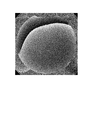
一例として、本撮像エコー507から生成した本実施例適用することなく生成した位相画像を図8に、本実施例1の図6の処理を適用して生成した位相画像を図9に示す。図8と比較して、本実施例を適用した図9の位相画像は、位相の不連続がなく、また、静磁場不均一に起因する大域的なアーチファクトもない画像となっている。
As an example, FIG. 8 shows a phase image generated from the
上述の実施例1では、本撮像エコー507にフィルタを適用してk空間上で静磁場不均一に起因する周波数帯域の位相成分を除去したが、実施例2では、本撮像エコー507の再構成画像についてフィルタを適用して、画像空間上で静磁場不均一に起因する位相成分を除去した画像を得る。この処理を図10を用いて説明する。
In the above-described first embodiment, a filter is applied to the
すなわち、静磁場不均一除去部203は、閾値周波数以下の前記低周波位相データを逆フーリエ変換して低周波位相画像を生成し、低周波位相画像からフィルタを生成し、このフィルタを本撮像で得た核磁気共鳴信号から生成した画像に適用することにより、周波数帯域の位相成分を除去する。例えば、静磁場不均一除去部203は、低周波位相画像をフィルタとし、本撮像で得た核磁気共鳴信号から生成した画像の画素値を低周波位相画像の画素値で除算することにより、周波数帯域の位相成分を除去する。
That is, the static magnetic field
[ステップS601〜S607]
S601からS606の各ステップは、実施例1と同様であるので説明を省略する。S607では、実施例1と同様に、S606で求めた低周波位相データDplを逆フーリエ変換し、低周波位相画像Splを算出する(式(6))。
[Steps S601 to S607]
Since each step from S601 to S606 is the same as that in the first embodiment, the description thereof is omitted. In S607, in the same manner as in Example 1, and the inverse Fourier transform low-frequency phase data Dp l obtained in S606, and calculates the low-frequency phase image Sp l (Equation (6)).
[ステップS608’]
次に、低周波位相画像Splの画素値(位相値)を用いて、偏角が位相値Spl、大きさが1の複素数Cpを生成し、その実部成分を画素値とする低周波実部画像Cpr、虚部成分を画素値とする低周波虚部画像Cpiをそれぞれ生成する。この低周波実部画像Cpr、低周波虚部画像Cpiを、実施例2では、静磁場不均一に起因する位相成分を除去するためのフィルタとして用いる。
[Step S608 ']
Next, using the pixel value (phase value) of the low-frequency phase image Sp l , a complex number Cp having a phase angle Sp l and a magnitude of 1 is generated, and the real frequency component is used as the pixel value. A partial image Cpr and a low-frequency imaginary part image Cpi each having an imaginary part component as a pixel value are generated. In the second embodiment, the low-frequency real part image Cpr and the low-frequency imaginary part image Cpi are used as filters for removing phase components caused by static magnetic field inhomogeneity.
[ステップS609’]
次に、本撮像エコー507から再構成した画像に、ステップ608’で生成したフィルタを適用し、静磁場不均一に起因する周波数帯域の位相成分を除去した画像を生成する。
[Step S609 ']
Next, the filter generated in
まず、本撮像エコー507の実部Emr、虚部Emiを逆フーリエ変換してFT後実部画像Smr、FT後虚部画像Smiを算出する(式(13),式(14))。
First, the real part Emr and the imaginary part Emi of the
![]()
![]()
![]()
![]()
求めたFT後実部画像Smr、FT後虚部画像Smiの各画素値を、フィルタである低周波画像実部Cpr、低周波画像虚部Cpiの各画素値で、式(15)、式(16)のように除算し、得られた値Fmr、Fmiをそれぞれ画素値とするフィルタ適用実部画像Fmr、フィルタ適用虚部画像Fmiをそれぞれ生成する。 The pixel values of the obtained post-FT real part image Smr and post-FT imaginary part image Smi are the pixel values of the low-frequency image real part Cpr and the low-frequency image imaginary part Cpi, which are filters. The division is performed as in 16) to generate a filter application real part image Fmr and a filter application imaginary part image Fmi each having the obtained values Fmr and Fmi as pixel values.
[ステップS610’]
最終的に振幅画像Smmを生成したい場合には、フィルタ適用実部画像Fmr、フィルタ適用虚部画像Fmiの画素値から、式(17)により振幅画像Smmの画素値を算出し、振幅画像Smmを生成する。また、arctan(Fmr/Fmi)を求めることにより、位相画像を生成することももちろん可能である。
[Step S610 ']
If the final desired to generate an amplitude image Sm m calculates filter applying real image Fmr, from the pixel value of the filter application imaginary part image FMI, the pixel value of the amplitude image Sm m by the equation (17), the amplitude image Generate Sm m . It is of course possible to generate a phase image by obtaining arctan (Fmr / Fmi).
![]()
![]()
実施例3として、実施例1のステップ605で求めた閾値周波数から低周波位相除去フィルタを作成し、これを用いて本撮像エコー507から静磁場不均一に起因する周波数帯域の位相成分を除去する処理について図11を用いて説明する。
As Example 3, a low-frequency phase removal filter is created from the threshold frequency obtained in
すなわち、実施例3において、静磁場不均一除去部203は、閾値周波数より大きい周波数帯域を透過する高周波透過フィルタを生成し、本撮像で得た核磁気共鳴信号に適用することにより、静磁場不均一に起因する周波数帯域の位相成分を除去する。例えば、静磁場不均一除去部203は、高周波透過フィルタをフーリエ変換した低周波位相除去フィルタを本撮像で得た核磁気共鳴信号に掛けることにより、上記周波数帯域の位相成分を除去する。
That is, in Example 3, the static magnetic field
[ステップS601〜S605]
S601からS605の各ステップは実施例1と同様であり、ステップ605により閾値周波数を求める。なお、実施例3では、実施例1のステップ606、607の周波数帯域の算出や、低周波位相データの逆フーリエ変換は行わない。
[Steps S601 to S605]
Steps S601 to S605 are the same as those in the first embodiment, and the threshold frequency is obtained in
[ステップS608”]
次に、図12のように、高周波域透過フィルタDFhpを作成する。高周波域透過フィルタDFhpは、カットオフ周波数が閾値周波数thresholdであり、閾値周波数以上の高周波帯域を透過帯域とし、閾値周波数より低い低周波帯域を遮断帯域とする高周波域透過フィルタDFhpを作成する。このとき、図12のグラフは、縦軸が係数、横軸が周波数である。この高周波域透過フィルタDFhpをフーリエ変換し、低周波位相除去フィルタSFhpを作成する(式(18))。
[Step S608 ”]
Next, as shown in FIG. 12, a high-frequency band transmission filter DF hp is created. The high-frequency transmission filter DF hp creates a high-frequency transmission filter DF hp whose cutoff frequency is the threshold frequency threshold, the high-frequency band above the threshold frequency is the transmission band, and the low-frequency band lower than the threshold frequency is the cutoff band . At this time, in the graph of FIG. 12, the vertical axis represents the coefficient, and the horizontal axis represents the frequency. The high frequency transmission filter DF hp is Fourier transformed to create a low frequency phase removal filter SF hp (Equation (18)).
![]()
![]()
[ステップS609”]
低周波位相除去フィルタSFhpを本撮像エコー507の実部Emr,虚部Emiにそれぞれ掛け合わせ、フィルタ適用エコー(静磁場不均一除去後エコー508)の実部Fmr,虚部Fmiを算出する(式(19),式(20))。
[Step S609 ”]
The real part Emr and the imaginary part Emi of the
![]()
![]()
![]()
![]()
[ステップS610]
この静磁場不均一除去後エコー508の実部Fmr、虚部Fmiから、実施例1のステップ610と同様に、式10、式11、式12等を用いて、所望の振幅画像Smmや位相画像を生成する。
[Step S610]
From the real part Fmr and the imaginary part Fmi of the
実施例4では、本撮像エコー507の高周波位相成分の信号強度の低減を防ぎながら、静磁場不均一に起因する周波数帯域の位相成分(低周波位相成分)を除去する。まず、本撮像エコー507に高周波位相除去フィルタを適用して、閾値周波数より高周波の位相成分を除去して、低周波位相成分のみが残ったエコーを用いて、低周波位相成分のみを本撮像エコー507から除去する。これにより、本撮像エコー507の高周波位相成分はフィルタ適用を受けないため、信号強度を低減することなく、高周波位相成分を取得することができる。この処理ステップを図13を用いて説明する。
In the fourth embodiment, the phase component (low frequency phase component) of the frequency band caused by the static magnetic field inhomogeneity is removed while preventing the signal intensity of the high frequency phase component of the
具体的には、静磁場不均一除去部203は、閾値周波数より小さい周波数帯域を透過する低周波透過フィルタを生成し、本撮像で得た核磁気共鳴信号に適用することにより、前記周波数帯域の核磁気共鳴信号を得て、これを本撮像で得た核磁気共鳴信号から差し引くことにより、静磁場不均一に起因する周波数帯域の位相成分が除去された信号を得る。例えば、静磁場不均一除去部203は、低周波透過フィルタをフーリエ変換した高周波位相除去フィルタを、本撮像で得た核磁気共鳴信号に掛けることにより、上記周波数帯域の核磁気共鳴信号を得る。
Specifically, the static magnetic field
[ステップS601〜S605]
S601からS605の各ステップは実施例1と同様であり、ステップ605により閾値周波数を求める。なお、実施例4では、実施例1のステップ606、607の周波数帯域の算出や、低周波位相データの逆フーリエ変換は行わない。
[Steps S601 to S605]
Steps S601 to S605 are the same as those in the first embodiment, and the threshold frequency is obtained in
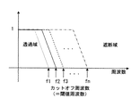
[ステップS620]
次に、図14のように、カットオフ周波数が閾値周波数thresholdであり、閾値周波数以下を透過帯域とし、閾値周波数より大きい周波数を遮断帯域とする低周波域透過フィルタDFlpを作成する。この低周波域透過フィルタDFlpをフーリエ変換して、高周波位相除去フィルタSFlpを作成する(式(21))。
[Step S620]
Next, as shown in FIG. 14, a low-frequency transmission filter DF lp is created in which the cutoff frequency is the threshold frequency threshold, the transmission frequency is equal to or lower than the threshold frequency, and the cutoff frequency is higher than the threshold frequency. The low-frequency transmission filter DF lp is Fourier-transformed to create a high-frequency phase removal filter SF lp (Expression (21)).
![]()
![]()
[ステップS621]
この高周波位相除去フィルタSFlpを本撮像エコーの実部Emr,虚部Emiに適用し、フィルタ適用エコーFmrlp、Fmilpを算出する(式(22)、式(23))。
[Step S621]
This high-frequency phase removal filter SF lp is applied to the real part Emr and the imaginary part Emi of the main imaging echo to calculate filter application echoes Fmr lp and Fmi lp (Equations (22) and (23)).
![]()
![]()
![]()
![]()
[ステップS622]
S621で求めた高周波位相除去フィルタ適用エコーFmrlp、Fmilpは、位相閾値threshold以下の低周波成分のみが残ったエコーである。すなわち、本撮像エコーの実部Emr、虚部Emiを高周波位相除去フィルタ適用エコーの実部Fmrlp、虚部Fmilpで除算することにより、静磁場不均一除去後エコー508の実部Fmr、虚部Fmiを算出することができる(式(24)、式(25))。
[Step S622]
The high frequency phase removal filter applied echoes Fmr lp and Fmi lp obtained in S621 are echoes in which only low frequency components equal to or lower than the phase threshold threshold remain. That is, by dividing the real part Emr and the imaginary part Emi of the imaging echo by the real part Fmr lp and the imaginary part Fmi lp of the echo applied with the high-frequency phase removal filter, the real part Fmr and imaginary part of the
[ステップS610]
この静磁場不均一除去後エコー508の実部Fmr、虚部Fmiから、実施例1のステップ610と同様に、式10、式11、式12等を用いて、所望の振幅画像Smmや位相画像を生成する。
[Step S610]
From the real part Fmr and the imaginary part Fmi of the
本実施例4では、低周波位相除去フィルタ適用エコー(静磁場不均一除去後エコー508)である高周波位相成分は、フィルタの適用を受けていない成分であるため、信号強度が大きい。よって、S610において生成される振幅画像Smmや位相画像としてコントラスト比の大きな鮮明な画像が得られる。 In the fourth embodiment, the high-frequency phase component that is the low-frequency phase removal filter application echo (echo 508 after static magnetic field inhomogeneous removal) is a component that has not been applied with a filter, and therefore has a high signal intensity. Therefore, a large clear image of the contrast ratio can be obtained as an amplitude image Sm m or phase image is generated in S610.
<実施例5から実施例8>
次に、実施例5から実施例8について説明する。これらの実施例は、操作者が設定した撮像条件に応じてカットオフ周波数を変更する例であって、そのため、前述の予備撮像を行う必要のない例である。
<Example 5 to Example 8>
Next, Example 5 to Example 8 will be described. These embodiments are examples in which the cutoff frequency is changed according to the imaging conditions set by the operator, and therefore, the above-described preliminary imaging need not be performed.
カットオフ周波数の変更に係わる撮像条件としては、1つの励起パルスの後に複数のエコーを計測するマルチエコーシーケンスにおけるエコートレイン(Echo Train Length:ETL)数やエコー間隔(Inter Echo Time:IET)、或いは撮像対象とする対象組織を想定するが、これらに限定されるものではない。マルチエコーシーケンスの例としては、高速スピンエコー (Fast Spin Echo:FSE)シーケンスやエコープラナー(Echo Planer Imaging:EPI)シーケンスが知られている。 Imaging conditions related to the change of the cutoff frequency include the number of echo trains (Echo Train Length: ETL) and echo interval (Inter Echo Time: IET) in a multi-echo sequence that measures multiple echoes after one excitation pulse, or A target tissue to be imaged is assumed, but is not limited thereto. As examples of the multi-echo sequence, a Fast Spin Echo (FSE) sequence and an Echo Planer Imaging (EPI) sequence are known.
これらの実施例は、ETL数を多くしたりIETを長くしたりして、エコーに静磁場不均一を多く取り込んでしまうような撮像条件・装置環境、または微小出血と腫瘍が混在する被検体において、シェーディングおよびアーチファクトを低減した画像を得るのに好適な例である。 In these embodiments, the number of ETLs is increased or the IET is lengthened, so that imaging conditions / apparatus environments that incorporate a large amount of static magnetic field inhomogeneity into echoes, or subjects with a mixture of microhemorrhages and tumors. This is an example suitable for obtaining an image with reduced shading and artifacts.
以下、実施例5から実施例8を詳細に説明する。なお、MRI装置の構成は前述の実施例1で説明した図1の構成と同様である。 Hereinafter, Examples 5 to 8 will be described in detail. The configuration of the MRI apparatus is the same as the configuration of FIG. 1 described in the first embodiment.
本実施例5では、操作者が設定したETL数に応じて本撮像で得られるk空間データに適用する低周波域透過フィルタのカットオフ周波数を変更する。このように予備計測に依らずにカットオフ周波数を求めることから、本実施例5は、予備計測を行うことはないが、予備計測に基づく閾値周波数(カットオフ周波数)の設定以降は前述の各実施例のいずれかと同様の処理を行う。以下、前述の各実施例と同様の処理については説明を省略し、主に本実施例特有の処理について詳細に説明する。 In the fifth embodiment, the cut-off frequency of the low-frequency transmission filter applied to the k-space data obtained by the main imaging is changed according to the number of ETLs set by the operator. Thus, since the cut-off frequency is obtained without depending on the preliminary measurement, the fifth embodiment does not perform the preliminary measurement, but after setting the threshold frequency (cut-off frequency) based on the preliminary measurement, The same processing as in any of the embodiments is performed. Hereinafter, the description of the same processing as that of each of the above-described embodiments will be omitted, and processing unique to the present embodiment will be mainly described in detail.
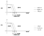
はじめに、本実施例5におけるETL数とカットオフ周波数との関係について説明する。本実施例5では、ETL数が多いときにはカットオフ周波数を大きくし、ETL数が少ないときにはカットオフ周波数を小さくする。例えば、ETL数に比例してカットオフ周波数を連続的に変更しても良いし、ETL数を数段階に分けて各段階に応じてカットオフ周波数を不連続的(段階的)に変更しても良い。低周波数域透過フィルタの形状(プロファイル)は、カットオフ周波数より低い低周波域では値が1であり、カットオフ周波数近傍の過渡領域では値が1から0に低減していき、カットオフ周波数から高い周波数域では値が0となるフィルタである。 First, the relationship between the number of ETLs and the cutoff frequency in the fifth embodiment will be described. In the fifth embodiment, the cutoff frequency is increased when the ETL number is large, and the cutoff frequency is decreased when the ETL number is small. For example, the cut-off frequency may be changed continuously in proportion to the number of ETLs, or the ETL number is divided into several steps and the cut-off frequency is changed discontinuously (stepwise) according to each step. Also good. The shape (profile) of the low-frequency transmission filter has a value of 1 in the low frequency range lower than the cutoff frequency, and decreases from 1 to 0 in the transient region near the cutoff frequency. This filter has a value of 0 in the high frequency range.
本実施例5の低周波数域透過フィルタの一例を図15(a)に基づいて説明する。図15(a)は、低周波域透過フィルタのカットオフ周波数とETL数との関係を示す図である。カットオフ周波数を、ETL数が1以上5未満(1≦ETL<5)のとき小(一点鎖線)とし、ETL数が5以上10未満(5≦ETL<10)のとき中(実線)とし、ETL数が10以上(10≦ETL)のときの大(点線)とする、3段階でカットオフ周波数を切り替える。もちろん、ETL数の各区分の範囲及び区分数(つまりカットオフ周波数の切り替え数)についてはこの限りではない。 An example of the low frequency band transmission filter of the fifth embodiment will be described with reference to FIG. FIG. 15 (a) is a diagram showing the relationship between the cutoff frequency of the low-frequency band transmission filter and the number of ETLs. The cut-off frequency is small (one-dot chain line) when the ETL number is 1 or more and less than 5 (1 ≦ ETL <5), and medium (solid line) when the ETL number is 5 or more and less than 10 (5 ≦ ETL <10). The cut-off frequency is switched in three steps, which is large (dotted line) when the ETL number is 10 or more (10 ≦ ETL). Of course, this does not apply to the range and the number of segments (that is, the number of cut-off frequencies) for each segment of the ETL number.
次に、本実施例5の機能ブロックを図2に示した画像処理部12内のブロック図に基づいて説明する。本実施例5では、予備計測を実施しないことから、周波数帯域算出部202内に位相画像生成部21及び閾値周波算出部22は必要なく、周波数帯域算出部202自身が、操作者が設定したETL数に応じてカットオフ周波数を上述の如く決定し、静磁場不均一除去部203が決定されたカットオフ周波数を有する低周波域透過フィルタを生成する。また、制御部11は、本計測におけるエコーの計測のみを行い、エコー計測部201は計測されたエコーをk空間に配置する。
Next, functional blocks of the fifth embodiment will be described based on the block diagram in the
次に、本実施例5の処理フローを図16に示すフローチャートに基づいて説明する。
ステップS1601で、操作者は表示装置110に表示されたGUIを介して、マルチエコーシーケンスの選択と、そのETL数やIETを設定入力する。
Next, the processing flow of the fifth embodiment will be described based on the flowchart shown in FIG.
In step S1601, the operator selects a multi-echo sequence and sets and inputs the ETL number and IET via the GUI displayed on the
ステップS1602で、周波数帯域算出部202は、ステップS1601で設定入力されたETL数に基づいて、低周波域透過フィルタのカットオフ周波数を設定する。具体的には図15(a)に示したように、カットオフ周波数を、1≦ETL<5のとき小とし(ステップS1603)、5≦ETL<10のとき中とし(ステップS1604)、10≦ETLのときの大とする(ステップS1605)。
In step S1602, the frequency
ステップS1606で、制御部11は、ステップS1601で選択されたマルチエコーシーケンスを実行してETL数分のマルチエコーを計測し、エコー計測部201は、計測されたエコーをk空間に配置する。
In step S1606, the
ステップS1607で、静磁場不均一除去部203は、ステップS1603〜S1605のいずれかで設定されたカットオフ周波数より低い周波数帯域を透過し、高い周波数帯域を遮断する低周波域透過フィルタDFlpを作成する。
In step S1607, the static magnetic field
ステップS1608で、静磁場不均一除去部203は、本撮像で得られたエコーが配置されたk空間データに対してステップS1607で求めた低周波域透過フィルタDFlpを適用する。具体的には、静磁場不均一除去部203は、この低周波域透過フィルタDFlpを、本撮像エコーの実部Emrおよび虚部Emiにそれぞれ掛け合わせ、フィルタ適用エコーの実部Fmr’および虚部Fmi’を算出する(式(26),式(27))。
In step S1608, the static magnetic field
![]()
![]()
![]()
![]()
ステップS1609で、画像再構成部204は、ステップS1608で得られたフィルタ適用エコーの実部Fmr’と虚部Fmi’を逆フーリエ変換して、低周波実部画像Cprと低周波虚部画像Cpiを算出する(式(28),式(29))。
In step S1609, the
![]()
![]()
![]()
![]()
この低周波実部画像Cpr、低周波虚部画像Cpiを、実施例5では、静磁場不均一に起因する位相成分を除去するための静磁場不均一除去フィルタとして用いる。 In the fifth embodiment, the low-frequency real part image Cpr and the low-frequency imaginary part image Cpi are used as a static magnetic field nonuniformity removal filter for removing phase components caused by the static magnetic field nonuniformity.
ステップS1610で、画像再構成部204は、本撮像エコーの実部Emr、虚部Emiを逆フーリエ変換してFT後実部画像Smr、FT後虚部画像Smiを算出する(式(13),式(14))。
In step S1610, the
ステップS1611で、静磁場不均一除去部203は、ステップS1610で求められたFT後実部画像Smr、FT後虚部画像Smiの各画素値を、ステップS1609で求めたれた静磁場不均一除去フィルタである低周波画像実部Cpr、低周波画像虚部Cpiの各画素値で、式(15)、式(16)のように除算し、得られた値Fmr、Fmiをそれぞれ画素値とするフィルタ適用実部画像Fmr、フィルタ適用虚部画像Fmiをそれぞれ生成する。
In step S1611, the static magnetic field
ステップS1612で、画像再構成部204は、最終的に振幅画像Smmを生成したい場合には、ステップS1611で求められたフィルタ適用実部画像Fmr、フィルタ適用虚部画像Fmiの画素値から、式(17)により振幅画像Smmの画素値を算出し、振幅画像Smmを生成する。また、arctan(Fmr/Fmi)を求めることにより、位相画像を生成することももちろん可能である。
以上までが本実施例5の処理フローの説明である。
In step S1612, the
The above is the description of the processing flow of the fifth embodiment.
以上、説明したように本実施例5は、ETL数に応じて低周波域透過フィルタのカットオフ周波数を変更する。これにより、エコーに静磁場不均一を多く取り込んでしまうような撮像条件・装置環境であっても、図9と同様に位相の不連続のない位相画像を得ることができる。その結果、シェーディングおよびアーチファクトを低減した画像を得ることができる。 As described above, the fifth embodiment changes the cut-off frequency of the low-frequency band transmission filter according to the number of ETLs. As a result, a phase image without phase discontinuity can be obtained in the same manner as in FIG. 9 even in an imaging condition / apparatus environment in which a large amount of static magnetic field inhomogeneity is captured in the echo. As a result, an image with reduced shading and artifacts can be obtained.
前述の実施例5は、ETL数に応じて低周波域透過フィルタのカットオフ周波数を変更する例であったが、本実施例6では、操作者が設定したIETに応じて本撮像で得られるk空間データに適用する低周波域透過フィルタのカットオフ周波数を変更する。このこと以外は前述の実施例5と同様なので、以下、前述の実施例5と同様の処理については説明を省略し、主に本実施例特有の処理について詳細に説明する。
The above-described
はじめに、本実施例6におけるIETとカットオフ周波数との関係について説明する。本実施例6では、IETが長いときにはカットオフ周波数を大きくし、IETが短いときにはカットオフ周波数を小さくする。例えば、IETに比例してカットオフ周波数を連続的に変更しても良いし、IETを数段階に分けて各段階に応じてカットオフ周波数を不連続的(段階的)に変更しても良い。なお、低周波数域透過フィルタの形状(プロファイル)は前述の実施例5で説明した図15(a)と同じである。 First, the relationship between IET and cutoff frequency in the sixth embodiment will be described. In the sixth embodiment, the cut-off frequency is increased when IET is long, and the cut-off frequency is decreased when IET is short. For example, the cutoff frequency may be changed continuously in proportion to the IET, or the IET may be divided into several stages, and the cutoff frequency may be changed discontinuously (stepwise) according to each stage. . Note that the shape (profile) of the low-frequency band transmission filter is the same as that in FIG. 15 (a) described in the fifth embodiment.
一例を図15(b)に示す。図15(b)に示す例は、低周波域透過フィルタのカットオフ周波数が、IETが7msec以下(IET≦7msec)のとき小(一点鎖線)とし、IETが7msecより大きく10msec未満(7msec<IET<10msec)のとき中(実線)とし、IETが10msec以上(10msec≦IET)のときの大(点線)とする、3段階でカットオフ周波数を切り替える。もちろん、IETの各区分の範囲及び区分数(つまりカットオフ周波数の切り替え数)についてはこの限りではない。 An example is shown in FIG. In the example shown in Fig. 15 (b), the cutoff frequency of the low-frequency transmission filter is small (dashed line) when the IET is 7 msec or less (IET ≤ 7 msec), and the IET is greater than 7 msec but less than 10 msec (7 msec <IET The cut-off frequency is switched in three steps: medium (solid line) when <10 msec) and large (dotted line) when IET is 10 msec or more (10 msec ≦ IET). Of course, the range of each IET section and the number of sections (that is, the number of cut-off frequencies) are not limited to this.
次に、本実施例6の機能ブロックを図2に示した画像処理部12内のブロック図に基づいて説明する。本実施例6では、周波数帯域算出部202自身が、操作者が設定したIETに応じてカットオフ周波数を上述の如く決定し、静磁場不均一除去部203が決定されたカットオフ周波数を有する低周波域透過フィルタを生成する。このこと以外は前述の実施例5と同様であるので詳細な説明を省略する。
Next, functional blocks of the sixth embodiment will be described based on the block diagram in the
次に、本実施例6の処理フローを図17に示すフローチャートに基づいて説明する。前述の実施例5と異なる処理内容のステップは、ステップS1702であり、それ以外は前述の実施例5と同様なので、以下ステップS1702について説明する。 Next, the processing flow of the sixth embodiment will be described based on the flowchart shown in FIG. The step of the processing content different from that of the above-described fifth embodiment is step S1702, and the other steps are the same as those of the fifth embodiment, so step S1702 will be described below.
ステップS1702で、周波数帯域算出部202は、ステップS1601で設定入力されたIETに基づいて、低周波域透過フィルタのカットオフ周波数を設定する。具体的には、カットオフ周波数を、IET≦7msecのとき小とし(ステップS1603)、7msec<IET<10msecのとき中とし(ステップS1604)、10msec≦IETのときの大とする(ステップS1605)。
In step S1702, the frequency
他のステップは前述の実施例5と同様である。以上までが本実施例6の処理フローの説明である。 Other steps are the same as those in the fifth embodiment. The above is the description of the processing flow of the sixth embodiment.
以上、説明したように本実施例6は、IETに応じて低周波域透過フィルタのカットオフ周波数を変更する。これにより、前述の実施例5と同様に、エコーに静磁場不均一を多く取り込んでしまうような撮像条件・装置環境であっても、図9と同様に位相の不連続のない位相画像を得ることができる。その結果、シェーディングおよびアーチファクトを低減した画像を得ることができる。 As described above, the sixth embodiment changes the cutoff frequency of the low-frequency band transmission filter according to IET. As a result, as in the above-described fifth embodiment, a phase image without phase discontinuity is obtained in the same manner as in FIG. 9 even in an imaging condition / apparatus environment in which a large amount of static magnetic field inhomogeneity is captured in an echo be able to. As a result, an image with reduced shading and artifacts can be obtained.
撮像対象に微小出血と腫瘍が混在する場合、腫瘍近傍で位相が不連続となってしまい、所望の画像にアーチファクトが発生する可能性がある。そこで、本実施例7は、前述の実施例5、6において、撮像条件として撮像対象の組織も考慮して、操作者が入力画面(GUI)上で撮像対象の組織を選択入力できるようにする。そして、前述の実施例5,6の撮像条件によるカットオフ周波数の変更が好適な撮像対象の組織(例えば、微小出血)が選択された場合に、実施例5、6を適用する。撮像対象として選択できる組織は、例えば「微小出血、微小出血と腫瘍」とすることができる。ただし、選択できる対象組織はこれらの2種類に限られない。 When microbleeds and tumors coexist in the imaging target, the phase becomes discontinuous near the tumor, and artifacts may occur in a desired image. Therefore, in the seventh embodiment, the operator can select and input the imaging target tissue on the input screen (GUI) in consideration of the imaging target tissue as the imaging condition in the fifth and sixth embodiments. . Then, Examples 5 and 6 are applied when an imaging target tissue (for example, microhemorrhage) suitable for changing the cutoff frequency according to the imaging conditions of Examples 5 and 6 is selected. The tissue that can be selected as the imaging target can be, for example, “microbleeding, microbleeding and tumor”. However, the target organizations that can be selected are not limited to these two types.
本実施例7の処理フローは、図16、図17に示した前述の実施例5,6の処理フローにおいて、ステップS1601とステップS1602との間に、操作者による対象組織の選択を受け付けて、対象組織を選択するステップS1801を設ける。特に、本実施例7では、ステップS1801で対象領域として微小血管を選択する場合を想定している。他の処理ステップについては前述の実施例5,6と同様であり詳細な説明を省略するが、実施例5に相当する処理フローを図18に、実施例6に相当する処理フローを図19に、それぞれ示す。 In the processing flow of the seventh embodiment, in the processing flow of the above-described fifth and sixth embodiments shown in FIGS. 16 and 17, the selection of the target tissue by the operator is accepted between step S1601 and step S1602, Step S1801 for selecting a target tissue is provided. In particular, the seventh embodiment assumes a case where a microvessel is selected as a target region in step S1801. The other processing steps are the same as those in the fifth and sixth embodiments, and detailed description thereof is omitted. However, the processing flow corresponding to the fifth embodiment is shown in FIG. 18, and the processing flow corresponding to the sixth embodiment is shown in FIG. , Respectively.
以上説明したように、本実施例7は、操作者による対象組織の選択を受け付け、選択された対象組織が微小出血の場合、前述の実施例5,6で説明した、撮像条件によるカットオフ周波数の変更を実施する。これにより、撮像対象が微小出血の場合、画像にアーチファクトが発生することを回避でき、画質を向上させることができる。 As described above, the seventh embodiment accepts the selection of the target tissue by the operator, and when the selected target tissue is microbleeding, the cutoff frequency according to the imaging condition described in the fifth and sixth embodiments described above. Implement changes. Thereby, when the imaging target is microbleeding, it is possible to avoid the occurrence of artifacts in the image and to improve the image quality.
以上の各実施例5から7は、ETL数又はIETに応じて低周波域透過フィルタのカットオフ周波数を変更する例を説明したが、ETL数とIETとを両方用いて(つまり組み合わせて)、これらの値に応じてカットオフ周波数を変更してもよい。ETL数とIETの区分条件の組み合わせは、ETL数とIETとでそれぞれカットオフ周波数を求め、いずれか高い方のカットオフ周波数としても良い。 In each of the above Examples 5 to 7, the example of changing the cutoff frequency of the low-frequency band transmission filter according to the ETL number or IET has been described, but using both the ETL number and the IET (that is, in combination), The cutoff frequency may be changed according to these values. For the combination of ETL number and IET classification conditions, a cut-off frequency is obtained for each ETL number and IET, and the higher cut-off frequency may be used.
撮像対象に微小出血と腫瘍が混在する場合、腫瘍近傍で位相が不連続となり、所望の画像にアーチファクトが発生する可能性があることは前述の実施例7で説明したとおりである。
As described in
この、腫瘍近傍の位相の不連続は、低周波域透過フィルタのカットオフ周波数を高くすることで解決できるが、カットオフ周波数が高過ぎると微小出血の描出に影響を及ぼす可能性がある。そのため、微小出血の描出にはできるだけ低いカットオフ周波数を持つフィルタを適用することが望ましい。 This phase discontinuity near the tumor can be solved by increasing the cut-off frequency of the low-frequency transmission filter, but if the cut-off frequency is too high, it may affect the depiction of microhemorrhage. For this reason, it is desirable to apply a filter having a cut-off frequency as low as possible to depict microbleeds.
そこで、本実施例8では、カットオフ周波数が異なる複数の低周波域通過フィルタを用意し、それぞれk空間データに適用し、低周波域通過フィルタ毎にフィルタ適用画像(フィルタ適用実部画像とフィルタ適用虚部画像)をそれぞれ生成する。そして、生成した複数のフィルタ適用画像を重ね合わせることで、微小出血の描出に最適でかつ腫瘍近傍における位相不連続に起因するアーチファクトのない画像を取得する。 Therefore, in the eighth embodiment, a plurality of low frequency pass filters having different cut-off frequencies are prepared and applied to k-space data, respectively, and a filter application image (filter application real part image and filter filter is applied to each low frequency pass filter. Applicable imaginary part images) are generated. Then, by superimposing the plurality of generated filter applied images, an image that is optimal for rendering minute bleeding and free from artifacts due to phase discontinuity in the vicinity of the tumor is acquired.
なお、本実施例8のアルゴリズムは、前述の実施例7で説明した「微小出血」が選択された場合に適用することも可能である。 Note that the algorithm of the eighth embodiment can also be applied when the “micro-bleeding” described in the seventh embodiment is selected.
次に、本実施例8のカットオフ周波数が異なる複数の低周波域通過フィルタの一例を図20に基づいて説明する。図20は、カットオフ周波数(閾値周波数)がf1(低周波数)〜fn(高周波数)(n≧2)の低周波域通過フィルタを重ねて示した図である。各低周波域通過フィルタのカットオフ周波数以外の基本的な形状(プロファイル)は、前述の実施例5で説明したとおりである。このように、通過域では1、遮断域では0であり、カットオフ周波数近傍の遷移領域の形状が同形であって、カットオフ周波数のみが異なる(したがって、通過域と遮断域の範囲が異なる)低周波域通過フィルタを複数用意する。 Next, an example of a plurality of low frequency band pass filters having different cutoff frequencies according to the eighth embodiment will be described with reference to FIG. FIG. 20 is a diagram in which low-frequency bandpass filters having cutoff frequencies (threshold frequencies) of f1 (low frequency) to fn (high frequency) (n ≧ 2) are overlapped. The basic shape (profile) other than the cut-off frequency of each low-frequency band pass filter is as described in the fifth embodiment. Thus, 1 in the pass band, 0 in the cut-off area, the shape of the transition region near the cut-off frequency is the same shape, only the cut-off frequency is different (thus, the range of the pass band and the cut-off area are different) Prepare multiple low-frequency pass filters.
次に、本実施例8の処理フローを図21に示すフローチャートに基づいて説明する。前述の実施例7と異なる処理ステップは、ステップ番号を2100以上としており、同一処理ステップについては、同じステップ番号を付している。以下、前述の実施例7と異なる処理ステップの処理内容のみを説明し、同一処理内容の処理ステップの説明は省略する。 Next, the processing flow of the eighth embodiment will be described based on the flowchart shown in FIG. The processing steps different from the above-described seventh embodiment have step numbers of 2100 or more, and the same processing steps are given the same step numbers. Hereinafter, only the processing contents of the processing steps different from those of the seventh embodiment will be described, and the description of the processing steps having the same processing contents will be omitted.
ステップS2101で、操作者は、対象領域として「微小出血と腫瘍」を選択する。 In step S2101, the operator selects “microhemorrhage and tumor” as the target region.
ステップS2107で、ステップS2101での「微小出血と腫瘍」の選択を受けて、静磁場不均一除去部203は、図20に示すような、カットオフ周波数が異なる複数の低周波域通過フィルタを作成する。そして、フィルタ選択カウンタiに1をセットする。
In step S2107, in response to the selection of “micro-bleeding and tumor” in step S2101, the static magnetic field
ステップS2108で、静磁場不均一除去部203は、カットオフ周波数がfi(1≦i≦n)の低周波域透過フィルタを選択する。
In step S2108, the static magnetic field
ステップS1608〜S1611で、ステップS2108で選択されたカットオフ周波数がfiの低周波域透過フィルタを用いて、この低周波域透過フィルタでのフィルタ適用画像(フィルタ適用実部画像、フィルタ適用虚部画像)を作成する。具体的な処理内容は前述の実施例5の通りである。 In steps S1608 to S1611, using the low-frequency transmission filter with the cut-off frequency fi selected in step S2108, filter application images (filter application real part image, filter application imaginary part image) with this low frequency transmission filter ). Specific processing contents are as described in the fifth embodiment.
ステップS2110で、静磁場不均一除去部203は、フィルタ選択カウンタiがnより小さいか否かを判定し、小さい場合(yes)には、ステップS2109に移行してiをインクリメント(1を加算)し、ステップS2108に移行して、次のカットオフ周波数の低周波域透過フィルタを選択する。逆に大きい場合(no)には、ステップS2111に移行する。
In step S2110, the static magnetic field
ステップS2111で、画像再構成部204は、ステップS1608〜S1611のループ処理で得られた各フィルタ適用画像を重ね合わせ(単純加算又は重み付け加算)て重ね合わせ画像(フィルタ適用実部重ね合わせ画像Fmrsum、フィルタ適用虚部重ね合わせ画像Fmisum)を得る。そして重ね合わせ画像から振幅画像を生成したい場合には、式(17)により振幅画像の画素値を算出し、振幅画像を生成する。また、arctan(Fmrsum/Fmisum)を求めることにより、位相画像を生成することももちろん可能である。
In step S2111, the
以上説明したように、本実施例8は、操作者による対象組織の選択を受け付け、選択された対象組織が微小出血と腫瘍の場合、カットオフ周波数が異なる複数の低周波域通過フィルタを用意し、低周波域通過フィルタ毎にフィルタ適用画像をそれぞれ生成して、生成した複数のフィルタ適用画像を重ね合わせる。これにより、微小出血の描出に最適でかつ腫瘍近傍における位相不連続に起因するアーチファクトのない画像を取得することができる。 As described above, the eighth embodiment accepts selection of a target tissue by an operator, and when the selected target tissue is a microbleed and a tumor, prepares a plurality of low-frequency pass filters having different cutoff frequencies. A filter application image is generated for each low frequency band pass filter, and the generated plurality of filter application images are superimposed. This makes it possible to acquire an image that is optimal for rendering microbleeds and that is free of artifacts due to phase discontinuity near the tumor.
10 撮像部、11 制御部、12 画像処理部、21 位相画像生成部、22 閾値周波数算出部、101 マグネット、102 傾斜磁場コイル、103 被検体、104 シーケンサ、105 傾斜磁場電源、106 高周波発生装置、107 プローブ、108 受信器、109 計算機、110 表示装置、111 記憶媒体、201 エコー計測部、202 周波数帯域算出部、203 静磁場不均一除去部、204 画像再構成部、205 画像表示部 10 imaging unit, 11 control unit, 12 image processing unit, 21 phase image generation unit, 22 threshold frequency calculation unit, 101 magnet, 102 gradient magnetic field coil, 103 subject, 104 sequencer, 105 gradient magnetic field power source, 106 high frequency generator, 107 probe, 108 receiver, 109 computer, 110 display device, 111 storage medium, 201 echo measurement unit, 202 frequency band calculation unit, 203 static magnetic field inhomogeneity removal unit, 204 image reconstruction unit, 205 image display unit
Claims (15)
前記制御部は、所定の予備撮像と、本撮像とを前記撮像部に実行させ、
前記画像処理部は、
前記予備撮像により取得した核磁気共鳴信号から、前記静磁場の不均一に起因する位相成分の周波数帯域を求める周波数帯域算出部と、
前記本撮像により取得された核磁気共鳴信号、および、前記本撮像により取得された核磁気共鳴信号から再構成した画像、のうちの少なくとも一方から前記周波数帯域の位相成分を除去する静磁場不均一除去部と
を含むことを特徴とする磁気共鳴イメージング装置。 An imaging unit for detecting a nuclear magnetic resonance signal generated from the subject by applying a high-frequency magnetic field and a gradient magnetic field to a subject placed in a static magnetic field; and a control unit for controlling the operation of the imaging unit; An image processing unit that performs an operation on the nuclear magnetic resonance signal and generates an image, and a magnetic resonance imaging apparatus comprising:
The control unit causes the imaging unit to execute predetermined preliminary imaging and main imaging,
The image processing unit
From the nuclear magnetic resonance signals acquired by the previous SL preliminary imaging, a frequency bandwidth calculation unit that calculates a frequency band of uneven due to the phase component of the static magnetic field,
Before SL nuclear magnetic resonance signals obtained by the imaging, and the static magnetic field to remove the phase components of the frequency band from at least one of the reconstructed image, from the nuclear magnetic resonance signals acquired by the imaging unsaturated A magnetic resonance imaging apparatus comprising a uniform removal unit.
前記周波数帯域算出部は、
前記予備撮像により取得した2組の核磁気共鳴信号から、前記部位における前記2組の核磁気共鳴信号の位相差の分布を表す位相画像を生成する位相画像生成部と、
前記位相画像をフーリエ変換して得た位相データの周波数分布を求め、前記周波数分布に基づいて前記位相データを高周波位相データと低周波位相データとに分離する閾値周波数を求め、前記閾値周波数以下の範囲を前記周波数帯域とする閾値周波数算出部と
を含むことを特徴とする磁気共鳴イメージング装置。 2. The magnetic resonance imaging apparatus according to claim 1, wherein the preliminary imaging is to acquire two sets of nuclear magnetic resonance signals for imaging a region by shifting an echo time,
The frequency band calculator is
Two sets of nuclear magnetic resonance signals acquired by the previous SL preliminary imaging, a phase image generator for generating a phase image representing the distribution of the phase difference between the two sets of nuclear magnetic resonance signal in the region,
Obtains a frequency distribution before Symbol phase data the phase image obtained by Fourier transform obtains frequency threshold separating the phase data in the high frequency phase data and the low frequency phase data based on the frequency distribution, less the threshold frequency And a threshold frequency calculation unit having the frequency band as the frequency band.
前記静磁場の中に置かれた前記被検体に所定の本撮像を実施して得た核磁気共鳴信号から生成した画像から、前記周波数帯域の位相成分を除去することを特徴とする磁気共鳴イメージング方法。 From a nuclear magnetic resonance signal obtained by performing predetermined preliminary imaging on a subject placed in a static magnetic field, obtain a frequency band of a phase component due to non-uniformity of the static magnetic field,
Magnetic resonance imaging, wherein a phase component of the frequency band is removed from an image generated from a nuclear magnetic resonance signal obtained by performing predetermined main imaging on the subject placed in the static magnetic field Method.
前記核磁気共鳴信号から画像を生成する画像処理部と、
前記静磁場の不均一に起因する前記画像の位相成分を除去する静磁場不均一除去部と、
撮像条件に応じてフィルタのカットオフ周波数を変更する周波数帯域算出部と、
を有し、
前記静磁場不均一除去部は、前記カットオフ周波数より低い周波数帯域を透過し、高い周波数帯域を遮断する低周波域透過フィルタを作成し、該作成した低周波域透過フィルタを前記核磁気共鳴信号に施して得た低周波画像を、静磁場不均一除去フィルタとして、前記画像に施して、前記静磁場の不均一に起因する前記画像の位相成分を除去することを特徴とする磁気共鳴イメージング装置。 The magnetic resonance imaging apparatus according to claim 1.
An image processing unit for generating an image from the nuclear magnetic resonance signal;
A static magnetic field non-uniformity removing unit that removes a phase component of the image caused by non-uniformity of the static magnetic field;
A frequency band calculator that changes the cutoff frequency of the filter according to the imaging conditions;
Have
The static magnetic field non-uniformity removing unit creates a low-frequency band transmission filter that transmits a frequency band lower than the cutoff frequency and cuts off a high frequency band, and the generated low-frequency band transmission filter is used as the nuclear magnetic resonance signal. A low frequency image obtained by applying to the image as a static magnetic field non-uniformity removal filter, and removing a phase component of the image caused by the non-uniformity of the static magnetic field .
前記撮像条件はETLとIETの少なくとも一方であり、
前記静磁場不均一除去部は、前記ETLとIETの少なくとも一方の値に応じて前記カットオフ周波数を変更することを特徴とする磁気共鳴イメージング装置。 The magnetic resonance imaging apparatus according to claim 13.
The imaging condition is at least one of ETL and IET,
The magnetic resonance imaging apparatus, wherein the static magnetic field nonuniformity removing unit changes the cutoff frequency according to at least one value of the ETL and IET.
前記撮像条件は撮像対象とする対象組織であり、
前記静磁場不均一除去部は、前記対象組織として、微小出血又は微小出血と腫瘍の選択に応じて、前記カットオフ周波数の変更を行うことを特徴とする磁気共鳴イメージング装置。 The magnetic resonance imaging apparatus according to claim 14.
The imaging condition is a target tissue to be imaged,
The magnetic resonance imaging apparatus according to claim 1, wherein the static magnetic field nonuniformity removing unit changes the cut-off frequency according to selection of microbleeding or microbleeding and tumor as the target tissue.
Priority Applications (1)
| Application Number | Priority Date | Filing Date | Title |
|---|---|---|---|
| JP2012266944A JP6013161B2 (en) | 2012-09-06 | 2012-12-06 | Magnetic resonance imaging apparatus and magnetic resonance imaging method |
Applications Claiming Priority (3)
| Application Number | Priority Date | Filing Date | Title |
|---|---|---|---|
| JP2012196068 | 2012-09-06 | ||
| JP2012196068 | 2012-09-06 | ||
| JP2012266944A JP6013161B2 (en) | 2012-09-06 | 2012-12-06 | Magnetic resonance imaging apparatus and magnetic resonance imaging method |
Publications (3)
| Publication Number | Publication Date |
|---|---|
| JP2014064880A JP2014064880A (en) | 2014-04-17 |
| JP2014064880A5 JP2014064880A5 (en) | 2016-01-21 |
| JP6013161B2 true JP6013161B2 (en) | 2016-10-25 |
Family
ID=50237053
Family Applications (2)
| Application Number | Title | Priority Date | Filing Date |
|---|---|---|---|
| JP2012266944A Active JP6013161B2 (en) | 2012-09-06 | 2012-12-06 | Magnetic resonance imaging apparatus and magnetic resonance imaging method |
| JP2014534317A Pending JPWO2014038441A1 (en) | 2012-09-06 | 2013-08-28 | Magnetic resonance imaging apparatus and magnetic resonance imaging method |
Family Applications After (1)
| Application Number | Title | Priority Date | Filing Date |
|---|---|---|---|
| JP2014534317A Pending JPWO2014038441A1 (en) | 2012-09-06 | 2013-08-28 | Magnetic resonance imaging apparatus and magnetic resonance imaging method |
Country Status (4)
| Country | Link |
|---|---|
| US (1) | US9746537B2 (en) |
| JP (2) | JP6013161B2 (en) |
| CN (1) | CN104507387B (en) |
| WO (1) | WO2014038441A1 (en) |
Families Citing this family (6)
| Publication number | Priority date | Publication date | Assignee | Title |
|---|---|---|---|---|
| JP6401930B2 (en) * | 2014-04-07 | 2018-10-10 | 株式会社日立製作所 | Magnetic resonance imaging system |
| KR101652048B1 (en) * | 2014-12-05 | 2016-08-29 | 삼성전자주식회사 | Magnetic resonance imaging apparatus and method for generating magnetic resonance image |
| US9805662B2 (en) * | 2015-03-23 | 2017-10-31 | Intel Corporation | Content adaptive backlight power saving technology |
| JP6595393B2 (en) * | 2016-04-04 | 2019-10-23 | 株式会社日立製作所 | Magnetic resonance imaging apparatus and image processing method |
| US11340323B2 (en) * | 2020-01-06 | 2022-05-24 | General Electric Company | Low acoustic noise magnetic resonance image acquisition |
| CN115607133B (en) * | 2022-09-26 | 2023-11-28 | 中科微影(泰州)医疗科技有限公司 | Magnetic resonance image phase unwrapping method |
Family Cites Families (16)
| Publication number | Priority date | Publication date | Assignee | Title |
|---|---|---|---|---|
| US5162737A (en) * | 1989-03-31 | 1992-11-10 | Hitachi, Ltd. | Multi-echo NMR imaging method |
| US5371465A (en) * | 1991-03-13 | 1994-12-06 | Hitachi, Ltd. | Inspection method and apparatus using nuclear magnetic resonance (NMR) |
| JP3544782B2 (en) * | 1996-04-16 | 2004-07-21 | 株式会社東芝 | Magnetic resonance diagnostic equipment |
| JP3041688B2 (en) * | 1998-08-07 | 2000-05-15 | 技術研究組合医療福祉機器研究所 | High spatial resolution magnetic resonance imaging system |
| JP4138258B2 (en) * | 1999-05-26 | 2008-08-27 | 株式会社日立メディコ | Magnetic resonance imaging system |
| JP3353826B2 (en) * | 1999-06-24 | 2002-12-03 | ジーイー横河メディカルシステム株式会社 | Magnetic field inhomogeneity measurement device, phase correction device, and magnetic resonance imaging device |
| JP2001238866A (en) * | 2000-03-01 | 2001-09-04 | Hitachi Ltd | Magnet resonance imaging apparatus |
| JP4619674B2 (en) * | 2004-03-24 | 2011-01-26 | 株式会社東芝 | Magnetic resonance imaging system |
| WO2007113992A1 (en) * | 2006-03-31 | 2007-10-11 | Hitachi Medical Corporation | Magnetic resonance imaging device and method |
| US7592812B2 (en) * | 2006-04-13 | 2009-09-22 | Kabushiki Kaisha Toshiba | Magnetic resonance imaging apparatus and static magnetic field correction method |
| EP2143036A4 (en) * | 2007-04-02 | 2012-01-18 | Univ Pennsylvania | Combined feature ensamble nutual information image registration |
| US7911208B2 (en) * | 2007-10-15 | 2011-03-22 | Siemens Aktiengesellschaft | Methods for rectification of B0 inhomogeneity effects in magnetic resonance images |
| US8085041B2 (en) * | 2008-04-10 | 2011-12-27 | General Electric Company | Three-point method and system for fast and robust field mapping for EPI geometric distortion correction |
| WO2011144958A1 (en) * | 2010-05-21 | 2011-11-24 | Commissariat A L'energie Atomique Et Aux Energies Alternatives | Method and apparatus for correcting bl - inhomogeneity in slice - selective mri using composite rf pulses |
| DE102014205888B3 (en) * | 2014-03-28 | 2015-05-28 | Siemens Aktiengesellschaft | Frequency monitoring of gradient pulses in magnetic resonance imaging |
| DE102014206311B3 (en) * | 2014-04-02 | 2015-10-08 | Siemens Aktiengesellschaft | Receiving system for local coils of a magnetic resonance tomography system |
-
2012
- 2012-12-06 JP JP2012266944A patent/JP6013161B2/en active Active
-
2013
- 2013-08-28 CN CN201380040328.XA patent/CN104507387B/en not_active Expired - Fee Related
- 2013-08-28 US US14/398,745 patent/US9746537B2/en not_active Expired - Fee Related
- 2013-08-28 JP JP2014534317A patent/JPWO2014038441A1/en active Pending
- 2013-08-28 WO PCT/JP2013/072966 patent/WO2014038441A1/en active Application Filing
Also Published As
| Publication number | Publication date |
|---|---|
| US20150276905A1 (en) | 2015-10-01 |
| WO2014038441A1 (en) | 2014-03-13 |
| US9746537B2 (en) | 2017-08-29 |
| CN104507387A (en) | 2015-04-08 |
| JP2014064880A (en) | 2014-04-17 |
| CN104507387B (en) | 2017-03-08 |
| JPWO2014038441A1 (en) | 2016-08-08 |
Similar Documents
| Publication | Publication Date | Title |
|---|---|---|
| JP6374065B2 (en) | Magnetic resonance imaging system | |
| US8436611B2 (en) | Magnetic resonance imaging (MRI) using SPIR and/or CHESS suppression pulses | |
| JP6013161B2 (en) | Magnetic resonance imaging apparatus and magnetic resonance imaging method | |
| JP6071905B2 (en) | Magnetic resonance imaging apparatus and area imaging method | |
| US20190365230A1 (en) | Functional Magnetic Resonance Imaging (fMRI) Methodology Using Transverse Relaxation Preparation and Non-Echo-Planar Imaging (EPI) Pulse Sequences | |
| JP6595393B2 (en) | Magnetic resonance imaging apparatus and image processing method | |
| JP6417406B2 (en) | MR imaging with enhanced susceptibility contrast | |
| WO2010120829A2 (en) | Method for reducing artifacts in magnetic resonance imaging | |
| WO2015190508A1 (en) | Magnetic resonance imaging device and method for creating water-fat separation image | |
| WO2016021603A1 (en) | Magnetic resonance imaging device, and magnetic resonance imaging method | |
| JP5808659B2 (en) | Magnetic resonance imaging apparatus and T1ρ imaging method | |
| WO2009081786A1 (en) | Magnetic resonance imaging device and magnetization rate enhancement image picking-up method | |
| JP6401930B2 (en) | Magnetic resonance imaging system | |
| JP6230882B2 (en) | Magnetic resonance imaging apparatus and echo time setting method | |
| JP2007260425A (en) | Nuclear magnetic resonance photographing device | |
| JP2007050278A (en) | Nuclear magnetic resonance photographing device | |
| JP6487554B2 (en) | Magnetic resonance imaging system | |
| JP4906952B2 (en) | Nuclear magnetic resonance imaging system | |
| JP5837354B2 (en) | Magnetic resonance imaging apparatus and magnetic resonance spectroscopy imaging method | |
| US20180267124A1 (en) | Magnetic resonance imaging apparatus and magnetic resonance imaging method | |
| JP2016140417A (en) | Magnetic resonance imaging apparatus, and irradiation phase control method of fse sequence | |
| JP2014200571A (en) | Magnetic resonance imaging apparatus, and binominal pulse control method |
Legal Events
| Date | Code | Title | Description |
|---|---|---|---|
| A521 | Request for written amendment filed |
Free format text: JAPANESE INTERMEDIATE CODE: A523 Effective date: 20151127 |
|
| A621 | Written request for application examination |
Free format text: JAPANESE INTERMEDIATE CODE: A621 Effective date: 20151127 |
|
| RD02 | Notification of acceptance of power of attorney |
Free format text: JAPANESE INTERMEDIATE CODE: A7422 Effective date: 20160330 |
|
| A711 | Notification of change in applicant |
Free format text: JAPANESE INTERMEDIATE CODE: A712 Effective date: 20160427 |
|
| TRDD | Decision of grant or rejection written | ||
| A01 | Written decision to grant a patent or to grant a registration (utility model) |
Free format text: JAPANESE INTERMEDIATE CODE: A01 Effective date: 20160906 |
|
| A61 | First payment of annual fees (during grant procedure) |
Free format text: JAPANESE INTERMEDIATE CODE: A61 Effective date: 20160921 |
|
| R150 | Certificate of patent or registration of utility model |
Ref document number: 6013161 Country of ref document: JP Free format text: JAPANESE INTERMEDIATE CODE: R150 |
|
| S111 | Request for change of ownership or part of ownership |
Free format text: JAPANESE INTERMEDIATE CODE: R313111 |
|
| R350 | Written notification of registration of transfer |
Free format text: JAPANESE INTERMEDIATE CODE: R350 |
|
| R250 | Receipt of annual fees |
Free format text: JAPANESE INTERMEDIATE CODE: R250 |
|
| R250 | Receipt of annual fees |
Free format text: JAPANESE INTERMEDIATE CODE: R250 |