JP6010754B2 - Push lock body and input device using the same - Google Patents
Push lock body and input device using the same Download PDFInfo
- Publication number
- JP6010754B2 JP6010754B2 JP2012124098A JP2012124098A JP6010754B2 JP 6010754 B2 JP6010754 B2 JP 6010754B2 JP 2012124098 A JP2012124098 A JP 2012124098A JP 2012124098 A JP2012124098 A JP 2012124098A JP 6010754 B2 JP6010754 B2 JP 6010754B2
- Authority
- JP
- Japan
- Prior art keywords
- operating
- operating body
- cam
- shaft
- input device
- Prior art date
- Legal status (The legal status is an assumption and is not a legal conclusion. Google has not performed a legal analysis and makes no representation as to the accuracy of the status listed.)
- Expired - Fee Related
Links
Images


Classifications
-
- F—MECHANICAL ENGINEERING; LIGHTING; HEATING; WEAPONS; BLASTING
- F16—ENGINEERING ELEMENTS AND UNITS; GENERAL MEASURES FOR PRODUCING AND MAINTAINING EFFECTIVE FUNCTIONING OF MACHINES OR INSTALLATIONS; THERMAL INSULATION IN GENERAL
- F16H—GEARING
- F16H25/00—Gearings comprising primarily only cams, cam-followers and screw-and-nut mechanisms
- F16H25/08—Gearings comprising primarily only cams, cam-followers and screw-and-nut mechanisms for interconverting rotary motion and reciprocating motion
- F16H25/12—Gearings comprising primarily only cams, cam-followers and screw-and-nut mechanisms for interconverting rotary motion and reciprocating motion with reciprocation along the axis of rotation, e.g. gearings with helical grooves and automatic reversal or cams
- F16H25/125—Gearings comprising primarily only cams, cam-followers and screw-and-nut mechanisms for interconverting rotary motion and reciprocating motion with reciprocation along the axis of rotation, e.g. gearings with helical grooves and automatic reversal or cams having the cam on an end surface of the rotating element
-
- G—PHYSICS
- G05—CONTROLLING; REGULATING
- G05G—CONTROL DEVICES OR SYSTEMS INSOFAR AS CHARACTERISED BY MECHANICAL FEATURES ONLY
- G05G7/00—Manually-actuated control mechanisms provided with one single controlling member co-operating with one single controlled member; Details thereof
- G05G7/02—Manually-actuated control mechanisms provided with one single controlling member co-operating with one single controlled member; Details thereof characterised by special provisions for conveying or converting motion, or for acting at a distance
- G05G7/08—Manually-actuated control mechanisms provided with one single controlling member co-operating with one single controlled member; Details thereof characterised by special provisions for conveying or converting motion, or for acting at a distance in which repeated movement of the controlling member moves the controlling member through a cycle of distinct positions
-
- H—ELECTRICITY
- H01—ELECTRIC ELEMENTS
- H01H—ELECTRIC SWITCHES; RELAYS; SELECTORS; EMERGENCY PROTECTIVE DEVICES
- H01H3/00—Mechanisms for operating contacts
- H01H3/02—Operating parts, i.e. for operating driving mechanism by a mechanical force external to the switch
- H01H3/08—Turn knobs
- H01H2003/085—Retractable turn knobs, e.g. flush mounted
-
- Y—GENERAL TAGGING OF NEW TECHNOLOGICAL DEVELOPMENTS; GENERAL TAGGING OF CROSS-SECTIONAL TECHNOLOGIES SPANNING OVER SEVERAL SECTIONS OF THE IPC; TECHNICAL SUBJECTS COVERED BY FORMER USPC CROSS-REFERENCE ART COLLECTIONS [XRACs] AND DIGESTS
- Y10—TECHNICAL SUBJECTS COVERED BY FORMER USPC
- Y10T—TECHNICAL SUBJECTS COVERED BY FORMER US CLASSIFICATION
- Y10T74/00—Machine element or mechanism
- Y10T74/18—Mechanical movements
- Y10T74/18056—Rotary to or from reciprocating or oscillating
- Y10T74/18296—Cam and slide
- Y10T74/18304—Axial cam
Description
本発明は、主に自動車の各種電子機器等の操作に用いられるプッシュロック体、及びこれを用いた入力装置に関するものである。 The present invention relates to a push lock body mainly used for operations of various electronic devices of automobiles, and an input device using the same.
近年、車室内のインストルメントパネルやコンソールボックス等に、様々な操作方式の入力装置を設け、これによってランプやオーディオ、エアコン等の各種電子機器の操作を行うものが増えており、使い易く、確実な操作を行えるものが求められている。 In recent years, input devices of various operation methods have been provided in instrument panels and console boxes in the passenger compartment, which has increased the number of devices that operate various electronic devices such as lamps, audio, and air conditioners. There is a need for a device that can perform various operations.
このような従来の入力装置について、図7を用いて説明する。 Such a conventional input device will be described with reference to FIG.
図7は従来の入力装置の斜視図であり、同図において、1は上下面に複数の配線パターン(図示せず)が形成された配線基板、2は可変抵抗器やエンコーダ等の回転操作型電子部品で、回転操作型電子部品2が配線基板1に実装されると共に、回転操作型電子部品2の回転軸(図示せず)に、絶縁樹脂製の操作体3が装着されて入力装置が構成されている。
FIG. 7 is a perspective view of a conventional input device. In FIG. 7,
そして、この入力装置がパネル4から操作体3を手前に突出させて、例えば運転席前方のインストルメントパネルに装着されると共に、回転操作型電子部品2がコネクタやリード線(図示せず)等を介して、自動車の電子回路(図示せず)に電気的に接続される。
The input device projects the
以上の構成において、操作体3を指でつまんで回転操作すると、回転操作型電子部品2の抵抗値が変化、あるいはスイッチ接点の電気的接離が行われ、この電気信号が車両の電子回路へ出力されて、例えば、ヘッドランプの照射角度の切換え等の操作が行なわれる。
In the above configuration, when the
つまり、インストルメントパネル等の、運転者の手の届く箇所に入力装置を配置し、この操作体3を操作することで、車両の様々な操作を容易に行うことができるように構成されているものであった。
That is, it is configured such that various operations of the vehicle can be easily performed by arranging the input device at a location that can be reached by the driver, such as an instrument panel, and operating the
なお、この出願の発明に関連する先行技術文献情報としては、例えば、特許文献1が知られている。
As prior art document information related to the invention of this application, for example,
しかしながら、上記従来の入力装置においては、指での回転操作が可能なように、操作体3がパネル4から常に10mm前後突出しているため、パネル4の他の押釦やツマミを操作する際に、操作体3への指の当接や誤操作が生じてしまう場合があるという課題があった。
However, in the conventional input device, since the
本発明は、このような従来の課題を解決するものであり、使い易く、確実な操作の可能なプッシュロック体、及びこれを用いた入力装置を提供することを目的とする。 The present invention solves such a conventional problem, and an object thereof is to provide a push lock body that is easy to use and can be reliably operated, and an input device using the same.
上記目的を達成するために本発明は、略円筒状で内周に上下方向に延びる複数の溝部と壁部が形成されたカバーと、下方が開口した略円筒状で、カバーから上方が突出し、カバーに上下動可能に収納された操作体と、操作体下面に回転可能に装着された略リング状の回転体と、外周に操作体を上下動可能に装着した操作軸と、操作軸と操作体の間に装着され操作体を上方へ付勢するばねと、底面中央部に略環状に配列された凹凸部が形成されたケースからなり、回転体外周に外方へ突出するカム部を設けると共に、壁部の下面に凹凸部に対向した鋸歯部を設け、ばねを、操作軸に設けた上下方向に延びる中央孔の底部と操作体の上部内側の下面との間に装着し、前記操作軸は前記操作体の回転操作に応じて回転し、操作体の上下動に応じて、カム部が壁部の鋸歯部とケースの凹凸部に順次弾接して、回転体が回転し、カム部が溝部に入ると操作体が上方へ移動した状態になり、カム部が鋸歯部に弾接すると操作体とカム体が下方に保持された状態になるようにしてプッシュロック体を形成すると共に、このプッシュロック体の操作軸下端に、回転操作型電子部品を装着して入力装置を構成したものであり、操作体を押圧操作すると、操作体上面がパネル面でロックされるため、指の操作体への当接や誤操作が生じづらくなると共に、再度操作体を押圧操作すると、ロックが外れて操作体がパネル面から突出した状態に復帰し、操作体により容易に回転操作型電子部品の操作が行えるため、使い易く、確実な操作の可能なプッシュロック体、及びこれを用いた入力装置を得ることができるという作用を有するものである。 In order to achieve the above object, the present invention has a substantially cylindrical shape with a cover formed with a plurality of grooves and walls extending in the vertical direction on the inner periphery, a substantially cylindrical shape with an opening at the bottom, and the upper portion projects from the cover, An operating body accommodated in the cover so as to be movable up and down, a substantially ring-shaped rotating body that is rotatably mounted on the lower surface of the operating body, an operating shaft that is mounted on the outer periphery so that the operating body can be moved up and down, an operating shaft and an operation It consists of a case that is mounted between the body and biases the operating body upward, and a case in which an uneven part arranged in a substantially annular shape is formed in the center of the bottom, and a cam part that protrudes outward is provided on the outer periphery of the rotating body In addition, a saw-tooth portion facing the uneven portion is provided on the lower surface of the wall portion, and the spring is mounted between the bottom portion of the central hole extending in the vertical direction provided on the operation shaft and the lower surface inside the upper portion of the operation body. shaft is rotated according to the rotation operation of the operating member, in response to vertical movement of the operation body, When the cam part enters the groove part, the operating body is moved upward, and the cam part is elastically applied to the saw tooth part. A push lock body is formed so that the operation body and the cam body are held downward when in contact with each other, and a rotary operation type electronic component is mounted on the lower end of the operation shaft of the push lock body to constitute an input device. When the operating body is pressed, the upper surface of the operating body is locked by the panel surface, so that it is difficult for a finger to come into contact with the operating body or erroneous operation. Push-lock body that is easy to use and can be reliably operated, and input using this, since the operation body returns to the state of protruding from the panel surface and the operation body can easily operate the rotary operation type electronic components. Can get the equipment Those having an effect of that.
以上のように本発明によれば、使い易く、確実な操作の可能なプッシュロック体、及びこれを用いた入力装置を実現することができるという有利な効果が得られる。 As described above, according to the present invention, it is possible to obtain an advantageous effect that it is possible to realize a push lock body that is easy to use and can be reliably operated, and an input device using the push lock body.
以下、本発明の実施の形態について、図1〜図6を用いて説明する。 Hereinafter, embodiments of the present invention will be described with reference to FIGS.
(実施の形態)
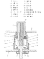
図1は本発明の一実施の形態による入力装置の断面図、図2は同分解斜視図であり、同図において、11は略円筒状でポリブチレンテレフタレートやABS等の絶縁樹脂製のカバーで、この内周には、図1や図4(a)の部分側面図に示すように、上下方向に複数の溝部11Aと壁部11Bが形成されると共に、壁部11B下面には段差のついた鋸歯部11Cが設けられている。
(Embodiment)
FIG. 1 is a cross-sectional view of an input device according to an embodiment of the present invention. FIG. 2 is an exploded perspective view of the input device. In the figure,
また、12はABS等の絶縁樹脂製の操作体で、上面にはドット状のマーキング12Aが形成されると共に、この操作体12が上方を突出させてカバー11内に上下動可能に収納されている。
そして、13は略リング状でポリオキシメチレン等の絶縁樹脂製の回転体で、操作体12下面に回転可能に装着されると共に、回転体13外周には外方へ突出する略台形状の複数のカム部13Aが設けられ、このカム部13Aがカバー11内周の溝部11Aに挿入されている。
さらに、14はポリブチレンテレフタレートやABS等の絶縁樹脂製の操作軸、15は同じく絶縁樹脂製のケースで、ケース15底面中央部には略環状に配列された凹凸部15Aが形成されると共に、この底面中央部の貫通孔に下端を挿通させて、操作軸14がケース15底面に載置されている。
Furthermore, 14 is an operation shaft made of an insulating resin such as polybutylene terephthalate or ABS, 15 is a case made of an insulating resin, and a concave and
そして、16はコイル状に巻回された鋼線等のばねで、このばね16が操作軸14外周に上下動可能に装着された操作体12下面と、操作軸14中央孔の底部の間にやや撓んだ状態で装着されて、プッシュロック体が構成されている。
A
また、21は紙フェノールやガラス入りエポキシ等の配線基板で、上下面には銅箔等によって複数の配線パターン(図示せず)が形成されると共に、この配線基板21上面にプッシュロック体が、操作軸14下端を貫通孔に挿通させて載置されている。
In addition, 21 is a wiring board such as paper phenol or epoxy containing glass, and a plurality of wiring patterns (not shown) are formed on the upper and lower surfaces by copper foil or the like. The lower end of the
さらに、22は可変抵抗器やエンコーダ等の回転操作型電子部品で、内部には導電金属製の可動接点22Aや、抵抗体または導電金属製の固定接点22Bが形成されると共に、この配線基板21下面に実装された回転操作型電子部品22の回転軸に、外周に操作体12を上下動可能に装着した操作軸14下端が装着されて、入力装置が構成されている。
Further,
また、このようなプッシュロック体や入力装置を製作する際、操作体12下端と操作軸14上端に設けられた係止爪12Bと14Aによって、操作体12や回転体13、操作軸14やばね16を一体に組み立てることができるため、これらの製作を容易に行えるようになっている。
Further, when manufacturing such a push lock body or an input device, the
つまり、図3の部分断面図に示すように、操作体12下面と操作軸14中央孔底部の間にばね16をやや撓んだ状態で装着すると共に、操作体12下端の係止爪12Bを回転体13下面に、操作軸14上端の係止爪14Aを回転体13上面に各々係止させて、これらを仮に一体化した後、これにカバー11やケース15等を組み立てることで、各部品の位置合わせが容易に行えると共に、ばね16の外れ等を防ぎ、簡易に組み立てられるように構成されている。
That is, as shown in the partial sectional view of FIG. 3, the
そして、このように構成された入力装置が、上面に文字や図形等の表示部23Aが形成されたパネル23から操作体12を上方に突出させて、例えば運転席前方のインストルメントパネルに装着されると共に、回転操作型電子部品22が配線基板21やコネクタ、リード線(図示せず)等を介して、自動車の電子回路(図示せず)に電気的に接続される。
Then, the input device configured as described above is mounted on, for example, an instrument panel in front of the driver's seat, with the
以上の構成において、パネル23から突出した操作体12を指でつまんで回転操作すると、操作軸14が回転すると共に、この下端によって回転操作型電子部品22の回転軸が回転し、可動接点22A先端が固定接点22Bを弾接摺動して、回転操作型電子部品22の抵抗値が変化、あるいはスイッチ接点の電気的接離が行われ、この電気信号が車両の電子回路へ出力されて、例えば、ヘッドランプの照射角度の切換え等の操作が行なわれる。
In the above configuration, when the
また、このような回転操作が終わった後、操作体12を指で押圧操作すると、操作体12がばね16を撓めながら下方へ移動すると共に、この下面に回転可能に装着された回転体13も下方へ移動するため、外周に突出形成された複数のカム部13Aがカバー11内周の溝部11A内を下方へ移動する。
Further, when the
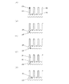
そして、操作体12が所定の距離だけ、例えば10mm前後押圧されると、図4(b)に示すように、略台形状のカム部13Aがケース15底面の凹凸部15Aに当接して回転体13が回転し、図4(c)に示すように、カム部13Aが凹凸部15Aの傾斜部から底部に摺動して、これ以上は操作体12を押圧できない状態となる。
Then, when the
さらに、この後、操作体12から指を離すと、ばね16の弾性復帰力によって操作体12と回転体13が上方へ移動し、図4(d)に示すように、カム部13Aが壁部11B下面の鋸歯部11Cに弾接して回転体13が回転し、図4(e)に示すように、カム部13Aが鋸歯部11Cの傾斜部から頂部に弾接摺動して、操作体12と回転体13がロックされ、図5の断面図に示すように、上面がパネル23上面からやや突出した状態で操作体12が保持される。
Further, after that, when the finger is released from the
また、操作体12を再び回転操作したい場合には、このロック状態から操作体12を再度押圧操作すると、図6(a)の部分側面図に示すように、カム部13Aが鋸歯部11Cから離れてロックが外れ、カム部13Aが凹凸部15Aに当接して回転体13が回転し、図6(b)に示すように、カム部13Aが凹凸部15Aの傾斜部から底部に摺動して、これ以上は操作体12を押圧できない状態となる。
If it is desired to rotate the
そして、この状態で操作体12から指を離すと、ばね16によって操作体12と回転体13が上方へ移動し、図6(c)に示すように、カム部13Aが鋸歯部11Cの傾斜部に弾接した後、図6(d)に示すように、回転体13が回転してカム部13Aが溝部11A下方へ移動し、図6(e)に示すように、カム部13Aが溝部11A内を上方へ移動して、操作体12が図1に示したパネル23上面から突出した元の状態に復帰する。
When the finger is released from the operating
つまり、インストルメントパネル等の、運転者の手の届く箇所に入力装置を配置し、この操作体12を回転操作することで、車両の様々な操作を容易に行うことができると共に、操作体12を回転操作しない場合には、操作体12を押圧操作し、上面がパネル23上面とほぼ同じ位置に操作体12をロックして、パネル23の他の押釦やツマミを操作した際にも、操作体12への指の当接や誤操作が生じづらいように構成されている。
That is, by arranging the input device at a location that can be reached by the driver, such as an instrument panel, and rotating the
すなわち、操作体12下面に回転可能に装着された回転体13外周の複数のカム部13Aが、操作体12の上下動に応じて、カバー11内周の溝部11Aや、壁部11B下面の鋸歯部11Cとケース15底面中央部の凹凸部15Aの間を、回転しながら移動し、鋸歯部11Cと凹凸部15Aに順次弾接して、回転体13が回転することによって、操作体12がパネル23面から突出し回転操作を行い易い状態と、操作体12上面がパネル23面でロックされ、指の操作体12への当接や誤操作が生じづらい状態に、操作体12を容易に保持することが可能なようになっている。
That is, the plurality of
また、押圧操作によって操作体12下面に装着された回転体13は回転するが、操作体12は上下動するだけで回転はしないため、操作体12上面のマーキング12Aと、パネル23上面の表示部23Aとの位置ずれを防ぎ、より容易に誤操作なく、回転操作型電子部品22の操作を行うことができる。
In addition, the rotating
さらに、回転体13は操作体12を押圧操作した際には、カム部13Aが凹凸部15Aを摺動して回転し、ばね16によって復帰する際には、ばね16の荷重が減少した状態で、カム部13Aが鋸歯部11Cに弾接して回転するため、カム部13Aが凹凸部15Aや鋸歯部11Cに当接する際の衝撃も少なく、静音化を図った操作を行えるようになっている。
Further, when the
なお、押圧操作によってロック動作を行うものとしては、操作体に略ハート形状のカムを設け、操作体の上下動に応じてカム内をピン等が移動する、いわゆるハートカム機構が一般に知られているが、本発明のように回転体13外周のカム部13Aが、カバー11の鋸歯部11Cとケース15の凹凸部15Aに順次弾接するように形成することで、プッシュロック体を使用部品が少なく、簡易な構成とすることができる。
As a mechanism for performing a locking operation by a pressing operation, a so-called heart cam mechanism is generally known in which a substantially heart-shaped cam is provided on an operating body, and a pin or the like moves in the cam according to the vertical movement of the operating body. However, as in the present invention, the
そして、回転体13には三方へ均等に突出する複数のカム部13Aが設けられ、この複数のカム部13Aが各々、複数の溝部11Aや凹凸部15A、鋸歯部11Cに弾接して、ロックや解除が行われるように構成されているため、操作体の一側面に形成したハートカムによってロックや解除を行うものに比べ、操作体12の傾き等も生じづらく、安定した操作が可能なようになっている。
The rotating
また、以上の説明では、回転体13外周に略台形状の複数のカム部13Aを設け、これがカバー11内周の溝部11Aや、ケース15底面中央部の凹凸部15Aを摺動する構成について説明したが、カム部13Aを六角形等の多角形状に形成した構成や、ケース15の凹凸部15Aを鋸歯形状に形成した構成としても、本発明の実施は可能である。
In the above description, a plurality of substantially
このように本実施の形態によれば、操作体12下面に装着された回転体13外周のカム部13Aが、操作体12の上下動に応じて、カバー11内周の壁部11B下面の鋸歯部11Cと、ケース15底面中央部の凹凸部15Aに順次弾接して、回転体13が回転するようにしてプッシュロック体を形成すると共に、このプッシュロック体の操作軸14下端に、回転操作型電子部品22を装着することによって、操作体12を押圧操作すると、操作体12上面がパネル23面でロックされるため、指の操作体12への当接や誤操作が生じづらくなると共に、再度操作体12を押圧操作すると、ロックが外れて操作体12がパネル23面から突出した状態に復帰し、操作体12により容易に回転操作型電子部品22の操作が行えるため、使い易く、確実な操作の可能なプッシュロック体、及びこれを用いた入力装置を得ることができるものである。
As described above, according to the present embodiment, the
そして、操作体12下端と操作軸14上端に係止爪12Bと14Aを設け、係止爪12Bを回転体13下面に、係止爪14Aを回転体13上面に各々係止させることによって、操作体12や回転体13、操作軸14やばね16を一体に組み立てることができるため、各部品の位置合わせが確実に行えると共に、容易に製作を行うことが可能となる。
Then, the engaging
本発明によるプッシュロック体及びこれを用いた入力装置は、使い易く、確実な操作が可能なものを実現することができるという有利な効果を有し、主に自動車の各種電子機器の操作用として有用である。 The push-lock body and the input device using the same according to the present invention have an advantageous effect that an easy-to-use and reliable operation can be realized, mainly for operation of various electronic devices of automobiles. Useful.
11 カバー
11A 溝部
11B 壁部
11C 鋸歯部
12 操作体
12A マーキング
12B 係止爪
13 回転体
13A カム部
14 操作軸
14A 係止爪
15 ケース
15A 凹凸部
16 ばね
21 配線基板
22 回転操作型電子部品
22A 可動接点
22B 固定接点
DESCRIPTION OF
Claims (3)
Priority Applications (2)
| Application Number | Priority Date | Filing Date | Title |
|---|---|---|---|
| JP2012124098A JP6010754B2 (en) | 2011-12-06 | 2012-05-31 | Push lock body and input device using the same |
| US13/688,651 US8969749B2 (en) | 2011-12-06 | 2012-11-29 | Push and lock unit and input device using the same |
Applications Claiming Priority (3)
| Application Number | Priority Date | Filing Date | Title |
|---|---|---|---|
| JP2011266586 | 2011-12-06 | ||
| JP2011266586 | 2011-12-06 | ||
| JP2012124098A JP6010754B2 (en) | 2011-12-06 | 2012-05-31 | Push lock body and input device using the same |
Publications (3)
| Publication Number | Publication Date |
|---|---|
| JP2013140768A JP2013140768A (en) | 2013-07-18 |
| JP2013140768A5 JP2013140768A5 (en) | 2015-04-30 |
| JP6010754B2 true JP6010754B2 (en) | 2016-10-19 |
Family
ID=48523038
Family Applications (1)
| Application Number | Title | Priority Date | Filing Date |
|---|---|---|---|
| JP2012124098A Expired - Fee Related JP6010754B2 (en) | 2011-12-06 | 2012-05-31 | Push lock body and input device using the same |
Country Status (2)
| Country | Link |
|---|---|
| US (1) | US8969749B2 (en) |
| JP (1) | JP6010754B2 (en) |
Families Citing this family (6)
| Publication number | Priority date | Publication date | Assignee | Title |
|---|---|---|---|---|
| KR20150120120A (en) * | 2014-04-17 | 2015-10-27 | 삼성전자주식회사 | Rotary knob assembly capable of moving up and down |
| CN106354193A (en) * | 2016-11-09 | 2017-01-25 | 洛阳市黄河软轴控制器股份有限公司 | Steering control mechanism with neutral position locking function |
| DE102017005533B4 (en) * | 2017-06-10 | 2023-03-09 | Diehl Ako Stiftung & Co. Kg | Kit for making a rotary selector switch |
| US10948056B2 (en) * | 2017-12-23 | 2021-03-16 | Continental Automotive Systems, Inc. | Elevation mechanism for a central input selector knob |
| FR3087547B1 (en) * | 2018-10-18 | 2021-10-08 | Thales Sa | UNIVERSAL CONTROL KNOB FOR CONTROL PANEL |
| TWM593645U (en) * | 2019-12-18 | 2020-04-11 | 大陸商東莞琦聯電子有限公司 | Control device to generate rotation damping by using elastic force |
Family Cites Families (6)
| Publication number | Priority date | Publication date | Assignee | Title |
|---|---|---|---|---|
| US4319106A (en) * | 1980-03-31 | 1982-03-09 | Armitage Ralph T | Push button switch |
| US4463231A (en) * | 1982-08-26 | 1984-07-31 | Cts Corporation | Push-push switch |
| US5132499A (en) * | 1989-05-16 | 1992-07-21 | Judco Manufacturing, Inc. | Pre-loaded switching apparatus and method of operation |
| DE10123536C1 (en) * | 2001-05-15 | 2003-01-23 | Methode Electronics Inc | Control device for an electrical switch with a retractable control button |
| US6621028B1 (en) * | 2002-09-13 | 2003-09-16 | Judco Manufacturing, Inc. | Quiet pushbutton switch ratchet mechanism |
| JP4951446B2 (en) | 2007-08-31 | 2012-06-13 | アルプス電気株式会社 | Push switch device |
-
2012
- 2012-05-31 JP JP2012124098A patent/JP6010754B2/en not_active Expired - Fee Related
- 2012-11-29 US US13/688,651 patent/US8969749B2/en active Active
Also Published As
| Publication number | Publication date |
|---|---|
| US20130139621A1 (en) | 2013-06-06 |
| JP2013140768A (en) | 2013-07-18 |
| US8969749B2 (en) | 2015-03-03 |
Similar Documents
| Publication | Publication Date | Title |
|---|---|---|
| JP6010754B2 (en) | Push lock body and input device using the same | |
| JP5151405B2 (en) | Input device | |
| JP5292903B2 (en) | Switch device for vehicle | |
| US7880572B2 (en) | Lever switch | |
| JP2009170399A (en) | Rotating operation type electronic component, and electronic device including same | |
| US8344275B2 (en) | Switching device | |
| JP4144242B2 (en) | Multi-directional operation switch | |
| JP5938554B2 (en) | Lever switch | |
| JP2016149280A (en) | Switch device with lock function | |
| JP2013045503A (en) | Input device | |
| JP4969343B2 (en) | Speed change operation device for vehicle | |
| JP2004273199A (en) | Switching device and manufacturing method of the same | |
| JP6263739B2 (en) | Multi-directional input device | |
| JP5549406B2 (en) | Rotation switch | |
| US6995650B2 (en) | Electrical part prevented from improper mounting on circuit board, and mounting structure for the electrical part | |
| JP2009032536A (en) | Vehicular switch | |
| JP4736972B2 (en) | Multi-directional operation switch | |
| JP6197174B2 (en) | Switch device | |
| JP5891355B2 (en) | Push switch | |
| JP5200710B2 (en) | Switch device | |
| JP2012150932A (en) | Rotating operation body and rotating operation-type input device using the same | |
| JP2014160640A (en) | Holding member and switch device | |
| JP2007073792A (en) | Rotary electric component | |
| JP2002015641A (en) | Rotary type electric parts | |
| JP6043957B2 (en) | Holding member and switch device using the same |
Legal Events
| Date | Code | Title | Description |
|---|---|---|---|
| A711 | Notification of change in applicant |
Free format text: JAPANESE INTERMEDIATE CODE: A711 Effective date: 20141003 |
|
| A521 | Request for written amendment filed |
Free format text: JAPANESE INTERMEDIATE CODE: A523 Effective date: 20150311 |
|
| A621 | Written request for application examination |
Free format text: JAPANESE INTERMEDIATE CODE: A621 Effective date: 20150311 |
|
| A977 | Report on retrieval |
Free format text: JAPANESE INTERMEDIATE CODE: A971007 Effective date: 20151221 |
|
| A131 | Notification of reasons for refusal |
Free format text: JAPANESE INTERMEDIATE CODE: A131 Effective date: 20160119 |
|
| A521 | Request for written amendment filed |
Free format text: JAPANESE INTERMEDIATE CODE: A523 Effective date: 20160307 |
|
| RD01 | Notification of change of attorney |
Free format text: JAPANESE INTERMEDIATE CODE: A7421 Effective date: 20160518 |
|
| TRDD | Decision of grant or rejection written | ||
| A01 | Written decision to grant a patent or to grant a registration (utility model) |
Free format text: JAPANESE INTERMEDIATE CODE: A01 Effective date: 20160809 |
|
| A61 | First payment of annual fees (during grant procedure) |
Free format text: JAPANESE INTERMEDIATE CODE: A61 Effective date: 20160822 |
|
| R151 | Written notification of patent or utility model registration |
Ref document number: 6010754 Country of ref document: JP Free format text: JAPANESE INTERMEDIATE CODE: R151 |
|
| LAPS | Cancellation because of no payment of annual fees |