JP6010566B2 - Leakage light removal structure and fiber laser - Google Patents
Leakage light removal structure and fiber laser Download PDFInfo
- Publication number
- JP6010566B2 JP6010566B2 JP2014018602A JP2014018602A JP6010566B2 JP 6010566 B2 JP6010566 B2 JP 6010566B2 JP 2014018602 A JP2014018602 A JP 2014018602A JP 2014018602 A JP2014018602 A JP 2014018602A JP 6010566 B2 JP6010566 B2 JP 6010566B2
- Authority
- JP
- Japan
- Prior art keywords
- cladding
- fiber
- clad
- covering material
- optical fiber
- Prior art date
- Legal status (The legal status is an assumption and is not a legal conclusion. Google has not performed a legal analysis and makes no representation as to the accuracy of the status listed.)
- Expired - Fee Related
Links
Images


Classifications
-
- H—ELECTRICITY
- H01—ELECTRIC ELEMENTS
- H01S—DEVICES USING THE PROCESS OF LIGHT AMPLIFICATION BY STIMULATED EMISSION OF RADIATION [LASER] TO AMPLIFY OR GENERATE LIGHT; DEVICES USING STIMULATED EMISSION OF ELECTROMAGNETIC RADIATION IN WAVE RANGES OTHER THAN OPTICAL
- H01S3/00—Lasers, i.e. devices using stimulated emission of electromagnetic radiation in the infrared, visible or ultraviolet wave range
- H01S3/09—Processes or apparatus for excitation, e.g. pumping
- H01S3/091—Processes or apparatus for excitation, e.g. pumping using optical pumping
- H01S3/094—Processes or apparatus for excitation, e.g. pumping using optical pumping by coherent light
- H01S3/094003—Processes or apparatus for excitation, e.g. pumping using optical pumping by coherent light the pumped medium being a fibre
- H01S3/094007—Cladding pumping, i.e. pump light propagating in a clad surrounding the active core
-
- G—PHYSICS
- G02—OPTICS
- G02B—OPTICAL ELEMENTS, SYSTEMS OR APPARATUS
- G02B6/00—Light guides; Structural details of arrangements comprising light guides and other optical elements, e.g. couplings
- G02B6/24—Coupling light guides
- G02B6/245—Removing protective coverings of light guides before coupling
-
- G—PHYSICS
- G02—OPTICS
- G02B—OPTICAL ELEMENTS, SYSTEMS OR APPARATUS
- G02B6/00—Light guides; Structural details of arrangements comprising light guides and other optical elements, e.g. couplings
- G02B6/24—Coupling light guides
- G02B6/26—Optical coupling means
- G02B6/264—Optical coupling means with optical elements between opposed fibre ends which perform a function other than beam splitting
-
- H—ELECTRICITY
- H01—ELECTRIC ELEMENTS
- H01S—DEVICES USING THE PROCESS OF LIGHT AMPLIFICATION BY STIMULATED EMISSION OF RADIATION [LASER] TO AMPLIFY OR GENERATE LIGHT; DEVICES USING STIMULATED EMISSION OF ELECTROMAGNETIC RADIATION IN WAVE RANGES OTHER THAN OPTICAL
- H01S3/00—Lasers, i.e. devices using stimulated emission of electromagnetic radiation in the infrared, visible or ultraviolet wave range
- H01S3/02—Constructional details
- H01S3/04—Arrangements for thermal management
- H01S3/0405—Conductive cooling, e.g. by heat sinks or thermo-electric elements
-
- H—ELECTRICITY
- H01—ELECTRIC ELEMENTS
- H01S—DEVICES USING THE PROCESS OF LIGHT AMPLIFICATION BY STIMULATED EMISSION OF RADIATION [LASER] TO AMPLIFY OR GENERATE LIGHT; DEVICES USING STIMULATED EMISSION OF ELECTROMAGNETIC RADIATION IN WAVE RANGES OTHER THAN OPTICAL
- H01S3/00—Lasers, i.e. devices using stimulated emission of electromagnetic radiation in the infrared, visible or ultraviolet wave range
- H01S3/05—Construction or shape of optical resonators; Accommodation of active medium therein; Shape of active medium
- H01S3/06—Construction or shape of active medium
- H01S3/063—Waveguide lasers, i.e. whereby the dimensions of the waveguide are of the order of the light wavelength
- H01S3/067—Fibre lasers
- H01S3/06704—Housings; Packages
-
- H—ELECTRICITY
- H01—ELECTRIC ELEMENTS
- H01S—DEVICES USING THE PROCESS OF LIGHT AMPLIFICATION BY STIMULATED EMISSION OF RADIATION [LASER] TO AMPLIFY OR GENERATE LIGHT; DEVICES USING STIMULATED EMISSION OF ELECTROMAGNETIC RADIATION IN WAVE RANGES OTHER THAN OPTICAL
- H01S3/00—Lasers, i.e. devices using stimulated emission of electromagnetic radiation in the infrared, visible or ultraviolet wave range
- H01S3/05—Construction or shape of optical resonators; Accommodation of active medium therein; Shape of active medium
- H01S3/06—Construction or shape of active medium
- H01S3/063—Waveguide lasers, i.e. whereby the dimensions of the waveguide are of the order of the light wavelength
- H01S3/067—Fibre lasers
- H01S3/06708—Constructional details of the fibre, e.g. compositions, cross-section, shape or tapering
- H01S3/06729—Peculiar transverse fibre profile
-
- H—ELECTRICITY
- H01—ELECTRIC ELEMENTS
- H01S—DEVICES USING THE PROCESS OF LIGHT AMPLIFICATION BY STIMULATED EMISSION OF RADIATION [LASER] TO AMPLIFY OR GENERATE LIGHT; DEVICES USING STIMULATED EMISSION OF ELECTROMAGNETIC RADIATION IN WAVE RANGES OTHER THAN OPTICAL
- H01S3/00—Lasers, i.e. devices using stimulated emission of electromagnetic radiation in the infrared, visible or ultraviolet wave range
- H01S3/09—Processes or apparatus for excitation, e.g. pumping
- H01S3/091—Processes or apparatus for excitation, e.g. pumping using optical pumping
- H01S3/094—Processes or apparatus for excitation, e.g. pumping using optical pumping by coherent light
- H01S3/0941—Processes or apparatus for excitation, e.g. pumping using optical pumping by coherent light of a laser diode
-
- G—PHYSICS
- G02—OPTICS
- G02B—OPTICAL ELEMENTS, SYSTEMS OR APPARATUS
- G02B6/00—Light guides; Structural details of arrangements comprising light guides and other optical elements, e.g. couplings
- G02B6/10—Light guides; Structural details of arrangements comprising light guides and other optical elements, e.g. couplings of the optical waveguide type
- G02B6/14—Mode converters
-
- G—PHYSICS
- G02—OPTICS
- G02B—OPTICAL ELEMENTS, SYSTEMS OR APPARATUS
- G02B6/00—Light guides; Structural details of arrangements comprising light guides and other optical elements, e.g. couplings
- G02B6/24—Coupling light guides
- G02B6/255—Splicing of light guides, e.g. by fusion or bonding
-
- G—PHYSICS
- G02—OPTICS
- G02B—OPTICAL ELEMENTS, SYSTEMS OR APPARATUS
- G02B6/00—Light guides; Structural details of arrangements comprising light guides and other optical elements, e.g. couplings
- G02B6/24—Coupling light guides
- G02B6/255—Splicing of light guides, e.g. by fusion or bonding
- G02B6/2558—Reinforcement of splice joint
-
- G—PHYSICS
- G02—OPTICS
- G02B—OPTICAL ELEMENTS, SYSTEMS OR APPARATUS
- G02B6/00—Light guides; Structural details of arrangements comprising light guides and other optical elements, e.g. couplings
- G02B6/24—Coupling light guides
- G02B6/42—Coupling light guides with opto-electronic elements
- G02B6/4296—Coupling light guides with opto-electronic elements coupling with sources of high radiant energy, e.g. high power lasers, high temperature light sources
-
- H—ELECTRICITY
- H01—ELECTRIC ELEMENTS
- H01S—DEVICES USING THE PROCESS OF LIGHT AMPLIFICATION BY STIMULATED EMISSION OF RADIATION [LASER] TO AMPLIFY OR GENERATE LIGHT; DEVICES USING STIMULATED EMISSION OF ELECTROMAGNETIC RADIATION IN WAVE RANGES OTHER THAN OPTICAL
- H01S3/00—Lasers, i.e. devices using stimulated emission of electromagnetic radiation in the infrared, visible or ultraviolet wave range
- H01S3/09—Processes or apparatus for excitation, e.g. pumping
- H01S3/091—Processes or apparatus for excitation, e.g. pumping using optical pumping
- H01S3/094—Processes or apparatus for excitation, e.g. pumping using optical pumping by coherent light
- H01S3/094049—Guiding of the pump light
- H01S3/094053—Fibre coupled pump, e.g. delivering pump light using a fibre or a fibre bundle
-
- H—ELECTRICITY
- H01—ELECTRIC ELEMENTS
- H01S—DEVICES USING THE PROCESS OF LIGHT AMPLIFICATION BY STIMULATED EMISSION OF RADIATION [LASER] TO AMPLIFY OR GENERATE LIGHT; DEVICES USING STIMULATED EMISSION OF ELECTROMAGNETIC RADIATION IN WAVE RANGES OTHER THAN OPTICAL
- H01S3/00—Lasers, i.e. devices using stimulated emission of electromagnetic radiation in the infrared, visible or ultraviolet wave range
- H01S3/09—Processes or apparatus for excitation, e.g. pumping
- H01S3/091—Processes or apparatus for excitation, e.g. pumping using optical pumping
- H01S3/094—Processes or apparatus for excitation, e.g. pumping using optical pumping by coherent light
- H01S3/09408—Pump redundancy
Landscapes
- Physics & Mathematics (AREA)
- Electromagnetism (AREA)
- Optics & Photonics (AREA)
- Engineering & Computer Science (AREA)
- Plasma & Fusion (AREA)
- General Physics & Mathematics (AREA)
- Microelectronics & Electronic Packaging (AREA)
- Lasers (AREA)
- Mechanical Coupling Of Light Guides (AREA)
- Optical Fibers, Optical Fiber Cores, And Optical Fiber Bundles (AREA)
- Optical Couplings Of Light Guides (AREA)
Description
本発明は、漏れ光除去構造に係り、特にファイバレーザの光ファイバの融着点などで生じる漏れ光を除去する漏れ光除去構造に関するものである。 The present invention relates to a leakage light removal structure, and more particularly to a leakage light removal structure for removing leakage light generated at a fusion point of an optical fiber of a fiber laser.
一般的に、光ファイバ同士を融着接続させる場合は、それぞれの光ファイバの端部の被覆材を一定の長さにわたり除去してクラッドを露出させた状態で2つの光ファイバが融着される(例えば、特許文献1)。図1は、このような方法により光ファイバ同士を融着させた状態を示すものである。図1に示される構造においては、補強部材500で囲まれた空間内で2つの光ファイバ510,610が融着されており、光ファイバ510の被覆材520の下流側端部が全周にわたって除去され、光ファイバ610の被覆材620の上流側端部が全周にわたって除去されている。露出された光ファイバ510のクラッド530の端部と光ファイバ610のクラッド630の端部とが融着点700で融着されている。
Generally, when optical fibers are fused and connected, the two optical fibers are fused in a state in which the cladding material is removed by removing the covering material at the end of each optical fiber over a certain length. (For example, patent document 1). FIG. 1 shows a state in which optical fibers are fused together by such a method. In the structure shown in FIG. 1, two
ここで、光ファイバ510,610の融着点700においては、光ファイバ510のコアを伝搬する光が、融着点700で生じた微小な曲がりや軸ずれによって出力側の光ファイバ610のクラッド630へと漏れてしまう。通常の光ファイバ同士の融着であれば、コアを伝搬する光のパワーが強くないために、それほど大きな問題とはならないが、ファイバレーザなどのハイパワー光を伝搬する光学系においては、融着点700に生じた不整合がわずかなものであったとしても、出力側の光ファイバ610のクラッド630にハイパワーの漏れ光が生じてしまう。
Here, at the
ここで、出力側の光ファイバ610の被覆材620の屈折率がクラッド630の屈折率よりも高い場合には、光ファイバ610のクラッド630に生じた漏れ光がクラッド630から被覆材620に入射し吸収される。
Here, when the refractive index of the
しかしながら、図1に示す構造では、被覆材620はクラッド630の全周を被覆しているため、クラッド630に生じた漏れ光は、被覆材620がクラッド630を被覆している最上流部642において局所的に被覆材620に入射することとなる。したがって、この最上流部642で漏れ光が局所的に被覆材620に吸収されてしまい、発熱や発火などの重大な事故が生じるおそれがある。
However, in the structure shown in FIG. 1, since the covering
本発明は、このような従来技術の問題点に鑑みてなされたもので、局所的な発熱や発火を生じることなく光ファイバに生じた漏れ光を効率的に除去することができる漏れ光除去構造を提供することを第1の目的とする。 The present invention has been made in view of such problems of the prior art, and a leakage light removal structure capable of efficiently removing leakage light generated in an optical fiber without causing local heat generation or ignition. It is a first object to provide
また、本発明は、高品質のレーザビームを出射することのできる信頼性の高いファイバレーザを提供することを第2の目的とする。 The second object of the present invention is to provide a highly reliable fiber laser capable of emitting a high-quality laser beam.
本発明の第1の態様によれば、局所的な発熱や発火を生じることなく光ファイバに生じた漏れ光を効率的に除去することができる漏れ光除去構造が提供される。この漏れ光除去構造は、コアと、上記コアを被覆し上記コアよりも屈折率の低いクラッドと、上記クラッドを被覆し上記クラッドよりも屈折率の高い被覆材とを有する光ファイバにおいて上記コアから上記クラッドへと漏れる漏れ光を除去するために使用される。この漏れ光除去構造は、上記光ファイバの一部を収容するファイバ収容部と、上記ファイバ収容部内で、上記光ファイバの長手方向に沿って上記被覆材の一部を延出させることにより上記クラッドの全周のうち一部を被覆する被覆材延出部と、上記ファイバ収容部内で、上記クラッドの全周のうち上記被覆材延出部以外の部分が露出したクラッド露出部とを備える。上記クラッド露出部は、上記クラッドの屈折率よりも低い屈折率の媒質又は樹脂に覆われている。 According to the first aspect of the present invention, there is provided a leakage light removing structure capable of efficiently removing leakage light generated in an optical fiber without causing local heat generation or ignition. This leakage light removing structure is formed from an optical fiber having a core , a cladding that covers the core and has a lower refractive index than the core, and a coating material that covers the cladding and has a higher refractive index than the cladding. Used to remove leaked light leaking into the cladding . The leakage light removing structure includes a fiber housing portion that accommodates a part of the optical fiber, and a portion of the covering material that extends in the longitudinal direction of the optical fiber within the fiber housing portion. A covering material extending portion that covers a part of the entire circumference of the cladding, and a cladding exposed portion in which the portion other than the covering material extending portion of the entire circumference of the cladding is exposed in the fiber housing portion. The cladding exposed portion is covered with a medium or resin having a refractive index lower than that of the cladding.
このような構成により、光ファイバ内のクラッドに漏れ光が生じて、この漏れ光がクラッドと被覆材延出部との界面に至ると、被覆材延出部の屈折率がクラッドの屈折率以上であるため、漏れ光は被覆材延出部に入射することとなり、漏れ光が被覆材延出部に放射される。これにより、漏れ光が原因で生じる発熱や発火を防止して出射光学系の信頼性を向上することができる。 With such a configuration, when light leaks in the clad in the optical fiber and this leaked light reaches the interface between the clad and the coating material extension, the refractive index of the coating material extension exceeds the refractive index of the cladding. Therefore, the leakage light is incident on the covering material extension portion, and the leakage light is radiated to the covering material extension portion. As a result, heat generation and ignition caused by leakage light can be prevented, and the reliability of the emission optical system can be improved.
さらに、被覆材延出部においては、上記クラッドの全周のうち一部でのみ被覆材延出部が延出しているため、被覆材延出部の最上流部で被覆材延出部に放射される漏れ光の量が、クラッドの全周が被覆材に覆われている従来構造に比べて低減される。したがって、漏れ光が被覆材で吸収されることによる局所的な発熱を緩和することができ、漏れ光除去構造の信頼性を向上させることができる。 Furthermore, in the covering material extension part, since the covering material extension part extends only on a part of the entire circumference of the cladding, the coating material extension part radiates to the covering material extension part at the most upstream part. The amount of leaked light is reduced compared to a conventional structure in which the entire circumference of the cladding is covered with a coating material. Therefore, local heat generation due to leakage light being absorbed by the coating material can be mitigated, and the reliability of the leakage light removal structure can be improved.
本発明の第2の態様によれば、高品質のレーザビームを出射することのできる信頼性の高いファイバレーザが提供される。このファイバレーザは、信号光を発生させる信号光発生器と、励起光を発生させる励起レーザダイオードと、クラッドポンプファイバとを備えている。上記クラッドポンプファイバは、上記信号光が伝搬するコアと、上記コアを被覆し上記励起光が伝搬するクラッドと、上記クラッドを被覆し上記クラッドよりも屈折率の高い被覆材とを有している。上記ファイバレーザは、上記クラッドポンプファイバに融着された出力側光ファイバと、上記出力側光ファイバのクラッドに生じた漏れ光を除去するように構成された上記漏れ光除去構造とを備えている。 According to the second aspect of the present invention, a highly reliable fiber laser capable of emitting a high-quality laser beam is provided. The fiber laser includes a signal light generator that generates signal light, a pump laser diode that generates pump light, and a cladding pump fiber. The clad pump fiber has a core through which the signal light propagates, a clad that covers the core and through which the excitation light propagates, and a coating material that coats the clad and has a higher refractive index than the clad. . The fiber laser includes an output-side optical fiber fused to the cladding pump fiber, and the leakage light removing structure configured to remove leakage light generated in the cladding of the output-side optical fiber. .
ここで、局所的な発熱をより抑えるためには、上記光ファイバの軸に垂直な断面において該軸を中心として180°以下の角度で上記被覆材延出部を形成することが好ましい。また、上記クラッド露出部を覆う媒質又は樹脂の屈折率は、上記被覆材の屈折率より低いことが好ましい。上記ファイバ収容部は、上記クラッド露出部に対向するように配置された、熱放射のよい放熱板を含んでいることが好ましい。 Here, in order to further suppress local heat generation, it is preferable to form the covering material extending portion at an angle of 180 ° or less around the axis in a cross section perpendicular to the axis of the optical fiber. Moreover, it is preferable that the refractive index of the medium or resin which covers the said clad exposure part is lower than the refractive index of the said coating | covering material. It is preferable that the fiber accommodating portion includes a heat radiating plate that is arranged to face the clad exposed portion and has good heat radiation.
本発明に係る漏れ光除去構造によれば、漏れ光を効率的に除去するとともに、漏れ光の放射による局所的な発熱を緩和して信頼性を向上させることができる。また、本発明に係るファイバレーザによれば、高品質のレーザビームを出射することのできる信頼性の高いファイバレーザを提供することができる。 According to the leakage light removing structure of the present invention, it is possible to efficiently remove the leakage light and to reduce the local heat generation due to the emission of the leakage light to improve the reliability. In addition, according to the fiber laser of the present invention, it is possible to provide a highly reliable fiber laser that can emit a high-quality laser beam.
以下、本発明に係る漏れ光除去構造の実施形態について図2から図6を参照して詳細に説明する。なお、図2から図6において、同一又は相当する構成要素には、同一の符号を付して重複した説明を省略する。 Hereinafter, embodiments of a leakage light removing structure according to the present invention will be described in detail with reference to FIGS. 2 to 6, the same or corresponding components are denoted by the same reference numerals, and redundant description is omitted.
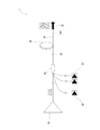
図2は、本発明の第1の実施形態におけるファイバレーザ1を示す模式図である。このファイバレーザ1は、信号光を発生させる信号光発生器10と、励起光を発生させる複数の励起レーザダイオード(LD)20と、信号光発生器10からの信号光と励起LD20からの励起光とを結合して出力する光カプラ30と、光カプラ30の出力端32に端部が接続されたクラッドポンプファイバ40と、クラッドポンプファイバ40の出力端42に接続された出力側光ファイバ140と、出力側光ファイバ140に設けられたアイソレータ52とを備えている。
FIG. 2 is a schematic diagram showing the fiber laser 1 in the first embodiment of the present invention. The fiber laser 1 includes a
図3は、クラッドポンプファイバ40を模式的に示す断面図である。図3に示すように、クラッドポンプファイバ40は、信号光発生器10により生成された信号光を伝搬するコア60と、コア60を被覆するクラッド(内部クラッド)62と、クラッド62を被覆する被覆材(外部クラッド)64とを備えている。コア60は、例えばYbなどの希土類元素が添加されたSiO2からなり、信号光を伝搬する信号光導波路となっている。クラッド62は、コア60の屈折率よりも低い屈折率の材料(例えばSiO2)からなる。被覆材64は、クラッド62の屈折率よりも低い屈折率の樹脂(例えば低屈折率ポリマー)からなる。これにより、クラッド62は励起光を伝搬する励起光導波路となる。
FIG. 3 is a cross-sectional view schematically showing the
このような構成のクラッドポンプファイバ40において、信号光発生器10からの信号光はコア60の内部を伝搬し、励起LD20からの励起光はクラッド62及びコア60の内部を伝搬する。励起光がコア60を伝搬する際に、コア60に添加された希土類元素イオンが励起光を吸収して励起され、誘導放出によってコア60中を伝搬する信号光が増幅される。
In the
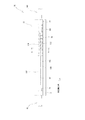
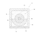
図4は、本発明の第1の実施形態における光ファイバの融着部の構造を模式的に示す図であり、図5は図4のV-V線断面図である。図4及び図5に示すように、略直方体状のファイバ収容部72内でクラッドポンプファイバ40とその下流側に位置する出力側光ファイバ140とが融着されている。すなわち、クラッドポンプファイバ40の被覆材64の下流側端部が全周にわたって除去され、出力側光ファイバ140の被覆材164の上流側端部が全周にわたって除去されて、露出されたクラッドポンプファイバ40のクラッド62の端部と出力側光ファイバ140のクラッド162とが融着点180で融着されている。本実施形態においては、出力側光ファイバ140の被覆材164の屈折率がクラッド162の屈折率よりも高い。なお、図5の符号160は、出力側光ファイバ140のコアを示している。
FIG. 4 is a diagram schematically showing the structure of the fused portion of the optical fiber in the first embodiment of the present invention, and FIG. 5 is a cross-sectional view taken along the line VV in FIG. As shown in FIGS. 4 and 5, the
この融着点180においては、クラッドポンプファイバ40のコアを伝搬する光が、融着点180で生じた微小な曲がりや軸ずれによって出力側光ファイバ140のクラッド162へと漏れてしまう。本実施形態では、このような漏れ光を除去する漏れ光除去構造70が設けられている。
At the
すなわち、ファイバ収容部72の内部における融着点180の下流側では、出力側光ファイバ140の全周のうち一部、例えば出力側光ファイバ140の軸に垂直な断面(図5)においてこの軸を中心として180°以上の角度(例えば180°)で被覆材164が除去されている。したがって、この範囲でクラッド162が被覆材164から露出しており、クラッド露出部174が形成されている。換言すれば、出力側光ファイバ140の軸を中心として180°以内の角度で、かつ出力側光ファイバ140の長手方向に沿って被覆材164の一部を延出させた被覆材延出部175が形成されている。図4に示すように、この被覆材延出部175は、出力側光ファイバ140の長手方向に沿って所定の長さだけ延びている。
That is, on the downstream side of the
また、ファイバ収容部72の内部には、使用する波長において出力側光ファイバ140のクラッド162及び被覆材164の屈折率より低い屈折率を有する樹脂(例えばUV硬化性樹脂)76が充填されており、この樹脂76により上記クラッド露出部174及び被覆材延出部175が覆われている。なお、図4に示す符号77は硬質の樹脂材であり、ファイバ収容部72の内部を封止している。
Further, the inside of the
このような構成において、クラッドポンプファイバ40のコアを伝搬する光が、融着点180で生じた微小な曲がりや軸ずれによって出力側光ファイバ140のクラッド162へと漏れると、クラッド162がエアクラッド182及びクラッド162の屈折率以下の屈折率を有する樹脂76により覆われているため、漏れ光はクラッド162内を伝搬する。そして、クラッド162を伝搬してきた漏れ光がクラッド162と被覆材延出部175との界面に至ると、被覆材延出部175の屈折率がクラッド162の屈折率以上であるため、漏れ光は被覆材延出部175に入射することとなり、漏れ光が被覆材延出部175に放射される。これにより、漏れ光除去構造70の後流側で漏れ光が原因で生じる発熱や発火を防止して出射光学系の信頼性を向上することができる。
In such a configuration, when light propagating through the core of the
ここで、本実施形態の被覆材延出部175においては、クラッド162の全周のうち一部が被覆材延出部175で被覆されているため、被覆材延出部175の最上流部で被覆材164に放射される漏れ光の量が、クラッドが全周にわたって被覆材に覆われている図1に示す従来構造に比べて低減される。したがって、漏れ光が被覆材164で吸収されることによる局所的な発熱を緩和することができ、漏れ光除去構造70の信頼性を向上させることができる。このとき、被覆材延出部175は、クラッド162の全周のうち一部を被覆するものであればよいが、局所的な発熱をより抑えるためには、出力側光ファイバ140の軸に垂直な断面(図5)においてこの軸を中心として180°以下の角度で被覆材延出部175を形成することが好ましい。
Here, in the covering
また、本実施形態では、被覆材164を覆う樹脂76の屈折率が被覆材164の屈折率よりも低いため、被覆材164に放射される漏れ光が被覆材164に閉じ込められ、伝搬していく間に被覆材164に吸収される。しかしながら、上述したように、クラッド162の全周のうち一部が被覆材延出部175で被覆されているので、単位長さ当たりの漏れ光の量が従来構造に比べて少なく発熱総量を抑えることができる。
In the present embodiment, since the refractive index of the
図5に示すように、ファイバ収容部72の一部は熱放射の良い放熱板78で構成されている。この放熱板78は、被覆材延出部175に対向するように配置されている。このように熱放射のよい放熱板78を被覆材延出部175に対向するように配置することで、漏れ光が被覆材164に入射することにより生じた被覆材164の熱を放熱板78を介して効果的に放熱することができる。このような放熱板78としては、例えば、アルミニウム又はアルミニウム合金による陽極酸化処理を表面に施した金属板が挙げられる。
As shown in FIG. 5, a part of the
上述した被覆材延出部175は、例えば図6に示されるような装置80を用いて形成することができる。この装置80は、出力側光ファイバ140の両端部を保持する保持部82と、出力側光ファイバ140の表面を削り取るカンナ状の刃84とを備えている。
The covering
この装置80を用いて被覆材延出部175を形成する際には、まず、保持部82により出力側光ファイバ140を保持した状態で、刃84を出力側光ファイバ140の表面に接触させ、出力側光ファイバ140の長手方向に所定の距離だけ移動させる。これにより、出力側光ファイバ140の表面にある被覆材164が上記所定の距離だけ剥離され、クラッド162が被覆材164から露出する。
When forming the covering
その後、保持部82で保持した出力側光ファイバ140を軸周りに例えば20°回転させるとともに、刃84を最初の位置に戻す。そして、刃84を再度出力側光ファイバ140の表面に接触させ、出力側光ファイバ140の長手方向に先ほどと同じ距離だけ移動させる。これにより、同じように被覆材164が上記所定の距離だけ剥離され、クラッド162が被覆材164から露出する。例えば、上記動作を合計で9回繰り返して出力側光ファイバ140の軸に垂直な断面(図5)において軸を中心として180°の範囲でクラッド162を被覆材164から露出させて上述した被覆材延出部175を形成する。このように、被覆材延出部175の大きさは、刃84による切削の回数とクラッドポンプファイバ40の回転角度によって制御することができる。
Thereafter, the output side
本実施形態では、クラッド露出部174及び被覆材延出部175を樹脂76で覆った例を説明したが、クラッド露出部174及び被覆材延出部175を樹脂76で覆わずに、クラッド162の屈折率(及び被覆材164の屈折率)よりも低い屈折率の媒質(空気など)でクラッド露出部174及び被覆材延出部175を覆ってもよい。ただし、被覆材延出部175がクラッド162の表面から剥離してしまうのを防止し、また、被覆材延出部175に吸収された漏れ光の熱を吸収させるためには、本実施形態のように、クラッド露出部174及び被覆材延出部175を樹脂76で覆うことが好ましい。また、ファイバ収容部72内のエアクラッド182にこの樹脂76を充填してもよい。
In the present embodiment, the example in which the cladding exposed
まず、比較例として図1に示す従来の漏れ光除去構造を作製した。光ファイバ510,610としてコアの径が10μm、クラッド530,630の径が400μmのものを用いた。光ファイバ510,610のそれぞれの被覆材520,620の端部を軸方向に沿って20mmずつ除去し、クラッド530,630を露出させた。エタノールを用いた超音波洗浄を行なって露出したクラッド530,630の表面を清浄した。
First, a conventional leakage light removing structure shown in FIG. 1 was produced as a comparative example.
石英ガラスと線膨張係数を合わせたセラミック部材からなる補強部材500内に、これらの光ファイバ510,610のクラッド530,630を突き合わせ融着した。補強部材500の両端と光ファイバ510,610との間は硬質のUV硬化性樹脂で固定した。
The
この状態でファイバレーザを600W出力で駆動させたところ、被覆材620の最上流部642が局所的に発熱し、約90℃まで温度が上昇した。被覆材620の耐熱性にもよるが、製造時の被覆材620の温度が上がると被覆材620が熱劣化し、光の吸収量が増え、さらに被覆材620の温度が上昇してしまうというネガティブフィードバックが発生してしまう。実験からの計算によると、このとき用いた被覆材620の寿命は約2万時間であり、非常に短い寿命であることがわかった。
When the fiber laser was driven at 600 W output in this state, the
同様の方法で、図4に示す光除去構造70を作製した。出力側光ファイバ140の被覆材164としては屈折率1.37の樹脂(ポリマークラッド)を用い、樹脂76としては屈折率1.32のUV硬化性樹脂を用いた。他の部材は上記従来の漏れ光除去構造で使用した部材と同様のものを使用した。
The
被覆材延出部175は、図6に示す装置80を用いて作製した。すなわち、保持部82により保持された出力側光ファイバ140の表面に刃84を接触させ、出力側光ファイバ140の長手方向に30mmだけ移動させてクラッド162を被覆材164から露出させた。そして、出力側光ファイバ140の角度を軸周りに20°ずつ回転させて合計9回の切削を行って合計180°の角度でクラッド162を露出させるようにした。
The covering
そして、従来の漏れ光除去構造に対する試験と同等の条件でファイバレーザを運転したところ、被覆材延出部175の温度上昇は最も高い箇所でも55℃となり、局所的な温度上昇が低減されることがわかった。この温度上昇結果に基づいて被覆材164の寿命を計算すると9万時間以上となり、従来の漏れ光除去構造と比べると寿命を圧倒的に長くすることができることがわかった。
When the fiber laser was operated under the same conditions as the test for the conventional leakage light removal structure, the temperature rise of the covering
これまで本発明の好ましい実施形態について説明したが、本発明は上述の実施形態に限定されず、その技術的思想の範囲内において種々異なる形態にて実施されてよいことは言うまでもない。 The preferred embodiments of the present invention have been described above, but the present invention is not limited to the above-described embodiments, and it goes without saying that the present invention may be implemented in various forms within the scope of the technical idea.
1 ファイバレーザ
10 信号光発生器
20 励起LD
30 光カプラ
32 出力端
40 クラッドポンプファイバ
42 出力端
52 アイソレータ
60 コア
62 クラッド
64 被覆材
70 光除去構造
72 ファイバ収容部
74 クラッド露出部
78 放熱板
140 出力側光ファイバ
160 コア
162 クラッド
164 被覆材
174 クラッド露出部
175 被覆材延出部
180 融着点
182 エアクラッド
1
DESCRIPTION OF
Claims (5)
前記光ファイバの一部を収容するファイバ収容部と、
前記ファイバ収容部内で、前記光ファイバの長手方向に沿って前記被覆材の一部を延出させることにより前記クラッドの全周のうち一部を被覆する被覆材延出部と、
前記ファイバ収容部内で、前記クラッドの全周のうち前記被覆材延出部以外の部分が露出したクラッド露出部であって、前記クラッドの屈折率よりも低い屈折率の媒質又は樹脂に覆われたクラッド露出部と、
を備えたことを特徴とする漏れ光除去構造。 Leaked light that leaks from the core to the cladding in an optical fiber that includes a core , a cladding that covers the core and has a lower refractive index than the core, and a coating that covers the cladding and has a higher refractive index than the cladding A light leakage removing structure for removing
A fiber housing for housing a portion of the optical fiber;
In the fiber accommodating portion, a covering material extending portion that covers a part of the entire circumference of the cladding by extending a part of the covering material along the longitudinal direction of the optical fiber, and
In the fiber housing portion, a portion of the entire circumference of the cladding other than the coating material extension portion is exposed, and is covered with a medium or resin having a refractive index lower than the refractive index of the cladding. A clad exposed portion;
A leakage light removing structure characterized by comprising:
励起光を発生させる励起レーザダイオードと、
前記信号光が伝搬するコアと、前記コアを被覆し前記励起光が伝搬するクラッドと、前記クラッドを被覆し前記クラッドよりも屈折率の高い被覆材とを有するクラッドポンプファイバと、
前記クラッドポンプファイバに融着された出力側光ファイバと、
前記出力側光ファイバのクラッドに生じた漏れ光を除去するように構成された請求項1から4のいずれか一項に記載された漏れ光除去構造と、
を備えたことを特徴とするファイバレーザ。 A signal light generator for generating signal light;
An excitation laser diode that generates excitation light;
A clad pump fiber having a core through which the signal light propagates, a clad that covers the core and through which the excitation light propagates, and a coating material that coats the clad and has a higher refractive index than the clad,
An output-side optical fiber fused to the cladding pump fiber;
The leakage light removal structure according to any one of claims 1 to 4, configured to remove leakage light generated in the cladding of the output side optical fiber;
A fiber laser comprising:
Priority Applications (5)
| Application Number | Priority Date | Filing Date | Title |
|---|---|---|---|
| JP2014018602A JP6010566B2 (en) | 2014-02-03 | 2014-02-03 | Leakage light removal structure and fiber laser |
| CN201580007037.XA CN105980897B (en) | 2014-02-03 | 2015-02-02 | Leak light removal construction and optical fiber laser |
| EP15743598.3A EP3104202B1 (en) | 2014-02-03 | 2015-02-02 | Structure for eliminating escaping light, and fiber laser |
| PCT/JP2015/052807 WO2015115637A1 (en) | 2014-02-03 | 2015-02-02 | Structure for eliminating escaping light, and fiber laser |
| US15/225,181 US10431951B2 (en) | 2014-02-03 | 2016-08-01 | Leakage light removal structure and fiber laser |
Applications Claiming Priority (1)
| Application Number | Priority Date | Filing Date | Title |
|---|---|---|---|
| JP2014018602A JP6010566B2 (en) | 2014-02-03 | 2014-02-03 | Leakage light removal structure and fiber laser |
Publications (2)
| Publication Number | Publication Date |
|---|---|
| JP2015145960A JP2015145960A (en) | 2015-08-13 |
| JP6010566B2 true JP6010566B2 (en) | 2016-10-19 |
Family
ID=53757202
Family Applications (1)
| Application Number | Title | Priority Date | Filing Date |
|---|---|---|---|
| JP2014018602A Expired - Fee Related JP6010566B2 (en) | 2014-02-03 | 2014-02-03 | Leakage light removal structure and fiber laser |
Country Status (5)
| Country | Link |
|---|---|
| US (1) | US10431951B2 (en) |
| EP (1) | EP3104202B1 (en) |
| JP (1) | JP6010566B2 (en) |
| CN (1) | CN105980897B (en) |
| WO (1) | WO2015115637A1 (en) |
Families Citing this family (12)
| Publication number | Priority date | Publication date | Assignee | Title |
|---|---|---|---|---|
| CN105068181B (en) * | 2015-08-28 | 2018-04-10 | 清华大学 | A kind of fiber cladding light filter and its manufacture method |
| CN105044836B (en) * | 2015-09-08 | 2018-04-10 | 清华大学 | A kind of cladding light stripper and its manufacture method, optical fiber laser for optical fiber |
| CN105633778B (en) * | 2016-03-28 | 2019-05-10 | 中国人民解放军国防科学技术大学 | High-order mode filters out fiber end face pumping coupler and preparation method thereof |
| JP6317388B2 (en) * | 2016-04-18 | 2018-04-25 | 株式会社フジクラ | Optical fiber fusion splicing structure and laser device manufacturing method |
| JP6381591B2 (en) | 2016-08-01 | 2018-08-29 | 株式会社フジクラ | Reinforced structure |
| JP6357207B2 (en) | 2016-10-04 | 2018-07-11 | 株式会社フジクラ | Optical fiber and fiber laser |
| JP6295305B1 (en) | 2016-10-04 | 2018-03-14 | 株式会社フジクラ | Optical fiber and fiber laser |
| JP6356856B1 (en) * | 2017-03-28 | 2018-07-11 | 株式会社フジクラ | Clad mode light removal structure and laser device |
| CN110361809B (en) * | 2019-07-05 | 2020-12-22 | 深圳联品激光技术有限公司 | Optical fiber, optical fiber cladding power filter, optical fiber laser and optical fiber preparation method |
| DE112021000793T5 (en) * | 2020-01-30 | 2022-12-22 | Nlight, Inc. | Capillary tube for stripping back-reflected light |
| WO2021198846A1 (en) * | 2020-03-29 | 2021-10-07 | Soreq Nuclear Research Center | Heating atom-vapor cell using an optical fiber |
| TWI789166B (en) * | 2021-12-14 | 2023-01-01 | 搏盟科技股份有限公司 | Gradient optical fiber cladding optical stripper and manufacturing method thereof |
Family Cites Families (10)
| Publication number | Priority date | Publication date | Assignee | Title |
|---|---|---|---|---|
| JPS63214630A (en) * | 1987-03-02 | 1988-09-07 | Sumitomo Electric Ind Ltd | Pressure sensor |
| US5926600A (en) * | 1997-05-22 | 1999-07-20 | Litton Systems, Inc. | Optical fiber for reducing optical signal reflections |
| US5995697A (en) * | 1997-11-19 | 1999-11-30 | Northern Telecom Limited | Partially coated grating optical fibre, method of producing same and fibre telecommunications system |
| US6549712B2 (en) * | 2001-05-10 | 2003-04-15 | 3M Innovative Properties Company | Method of recoating an optical fiber |
| US7251401B2 (en) * | 2005-09-16 | 2007-07-31 | Matshsita Electric Industrial Co., Ltd. | Fiber coating processing and slitting for non-confined light leakage |
| WO2007148127A2 (en) * | 2006-06-23 | 2007-12-27 | Gsi Group Limited | Fibre laser system |
| JP2009069492A (en) * | 2007-09-13 | 2009-04-02 | Omron Corp | Optical fiber and optical apparatus |
| JP2009116076A (en) | 2007-11-07 | 2009-05-28 | Mitsubishi Electric Corp | Optical fiber fused part holding structure |
| JP5434703B2 (en) * | 2010-03-11 | 2014-03-05 | オムロン株式会社 | Optical fiber connection structure, laser irradiation apparatus and laser processing apparatus |
| US8665916B2 (en) | 2011-06-29 | 2014-03-04 | Panasonic Corporation | Fiber laser |
-
2014
- 2014-02-03 JP JP2014018602A patent/JP6010566B2/en not_active Expired - Fee Related
-
2015
- 2015-02-02 EP EP15743598.3A patent/EP3104202B1/en not_active Not-in-force
- 2015-02-02 CN CN201580007037.XA patent/CN105980897B/en not_active Expired - Fee Related
- 2015-02-02 WO PCT/JP2015/052807 patent/WO2015115637A1/en active Application Filing
-
2016
- 2016-08-01 US US15/225,181 patent/US10431951B2/en active Active
Also Published As
| Publication number | Publication date |
|---|---|
| JP2015145960A (en) | 2015-08-13 |
| CN105980897A (en) | 2016-09-28 |
| US20160336711A1 (en) | 2016-11-17 |
| EP3104202A1 (en) | 2016-12-14 |
| WO2015115637A1 (en) | 2015-08-06 |
| EP3104202B1 (en) | 2018-12-05 |
| US10431951B2 (en) | 2019-10-01 |
| CN105980897B (en) | 2019-04-23 |
| EP3104202A4 (en) | 2017-11-01 |
Similar Documents
| Publication | Publication Date | Title |
|---|---|---|
| JP6010566B2 (en) | Leakage light removal structure and fiber laser | |
| JP6010565B2 (en) | Excess light removal structure and fiber laser | |
| JP5621930B2 (en) | Fiber laser | |
| JP4954737B2 (en) | Optical amplification system, optical fiber laser and optical fiber amplifier using the same | |
| US7409122B2 (en) | End face structure of optical fiber, optical fiber laser, and laser processing apparatus | |
| US8433161B2 (en) | All glass fiber laser cladding mode stripper | |
| JP5786143B2 (en) | Fiber parts and laser equipment | |
| JP6356856B1 (en) | Clad mode light removal structure and laser device | |
| JP6126562B2 (en) | Fiber optic equipment | |
| JP5235525B2 (en) | Laser light transmission device and fiber laser oscillator including the same | |
| JP5641496B2 (en) | Laser equipment | |
| JP2016212427A (en) | Optical fiber device | |
| WO2020241363A1 (en) | Optical fiber device | |
| WO2020045569A1 (en) | Cladding mode light removal structure, laser device, and method for manufacturing cladding mode light removal structure | |
| JP2021043396A (en) | Clad-mode stripper, laser device and manufacturing method for clad-mode stripper |
Legal Events
| Date | Code | Title | Description |
|---|---|---|---|
| A131 | Notification of reasons for refusal |
Free format text: JAPANESE INTERMEDIATE CODE: A131 Effective date: 20160105 |
|
| A521 | Request for written amendment filed |
Free format text: JAPANESE INTERMEDIATE CODE: A523 Effective date: 20160304 |
|
| TRDD | Decision of grant or rejection written | ||
| A01 | Written decision to grant a patent or to grant a registration (utility model) |
Free format text: JAPANESE INTERMEDIATE CODE: A01 Effective date: 20160823 |
|
| A61 | First payment of annual fees (during grant procedure) |
Free format text: JAPANESE INTERMEDIATE CODE: A61 Effective date: 20160916 |
|
| R150 | Certificate of patent or registration of utility model |
Ref document number: 6010566 Country of ref document: JP Free format text: JAPANESE INTERMEDIATE CODE: R150 |
|
| R250 | Receipt of annual fees |
Free format text: JAPANESE INTERMEDIATE CODE: R250 |
|
| R250 | Receipt of annual fees |
Free format text: JAPANESE INTERMEDIATE CODE: R250 |
|
| LAPS | Cancellation because of no payment of annual fees |