JP6009449B2 - Echogenic nerve block device and system - Google Patents
Echogenic nerve block device and system Download PDFInfo
- Publication number
- JP6009449B2 JP6009449B2 JP2013533323A JP2013533323A JP6009449B2 JP 6009449 B2 JP6009449 B2 JP 6009449B2 JP 2013533323 A JP2013533323 A JP 2013533323A JP 2013533323 A JP2013533323 A JP 2013533323A JP 6009449 B2 JP6009449 B2 JP 6009449B2
- Authority
- JP
- Japan
- Prior art keywords
- echogenic
- catheter
- needle
- shaft
- tip
- Prior art date
- Legal status (The legal status is an assumption and is not a legal conclusion. Google has not performed a legal analysis and makes no representation as to the accuracy of the status listed.)
- Active
Links
- 210000005036 nerve Anatomy 0.000 title claims description 35
- 239000000463 material Substances 0.000 claims description 74
- 238000000576 coating method Methods 0.000 claims description 39
- 239000011248 coating agent Substances 0.000 claims description 32
- 230000005641 tunneling Effects 0.000 claims description 29
- 238000003384 imaging method Methods 0.000 claims description 28
- 238000000034 method Methods 0.000 claims description 27
- 239000012530 fluid Substances 0.000 claims description 14
- 210000004872 soft tissue Anatomy 0.000 claims description 12
- 238000007920 subcutaneous administration Methods 0.000 claims description 4
- 210000003484 anatomy Anatomy 0.000 claims description 3
- 239000007788 liquid Substances 0.000 claims description 2
- 239000000126 substance Substances 0.000 claims 1
- 239000011521 glass Substances 0.000 description 21
- 229910052751 metal Inorganic materials 0.000 description 20
- 239000002184 metal Substances 0.000 description 20
- 229920000642 polymer Polymers 0.000 description 13
- 239000011324 bead Substances 0.000 description 12
- 229910000684 Cobalt-chrome Inorganic materials 0.000 description 9
- 239000010952 cobalt-chrome Substances 0.000 description 9
- UQZIWOQVLUASCR-UHFFFAOYSA-N alumane;titanium Chemical compound [AlH3].[Ti] UQZIWOQVLUASCR-UHFFFAOYSA-N 0.000 description 8
- 229920003229 poly(methyl methacrylate) Polymers 0.000 description 8
- 239000010453 quartz Substances 0.000 description 8
- VYPSYNLAJGMNEJ-UHFFFAOYSA-N silicon dioxide Inorganic materials O=[Si]=O VYPSYNLAJGMNEJ-UHFFFAOYSA-N 0.000 description 8
- 239000000017 hydrogel Substances 0.000 description 7
- 239000011159 matrix material Substances 0.000 description 7
- 239000002245 particle Substances 0.000 description 7
- 238000004519 manufacturing process Methods 0.000 description 5
- 238000012800 visualization Methods 0.000 description 5
- NRTOMJZYCJJWKI-UHFFFAOYSA-N Titanium nitride Chemical compound [Ti]#N NRTOMJZYCJJWKI-UHFFFAOYSA-N 0.000 description 4
- 239000000654 additive Substances 0.000 description 4
- 230000000996 additive effect Effects 0.000 description 4
- 238000012377 drug delivery Methods 0.000 description 4
- 238000001125 extrusion Methods 0.000 description 4
- 239000007789 gas Substances 0.000 description 4
- PCHJSUWPFVWCPO-UHFFFAOYSA-N gold Chemical compound [Au] PCHJSUWPFVWCPO-UHFFFAOYSA-N 0.000 description 4
- 229910052737 gold Inorganic materials 0.000 description 4
- 239000010931 gold Substances 0.000 description 4
- 239000012528 membrane Substances 0.000 description 4
- 239000004926 polymethyl methacrylate Substances 0.000 description 4
- 230000008569 process Effects 0.000 description 4
- 239000007787 solid Substances 0.000 description 4
- 210000001519 tissue Anatomy 0.000 description 4
- MTPVUVINMAGMJL-UHFFFAOYSA-N trimethyl(1,1,2,2,2-pentafluoroethyl)silane Chemical compound C[Si](C)(C)C(F)(F)C(F)(F)F MTPVUVINMAGMJL-UHFFFAOYSA-N 0.000 description 4
- BQCADISMDOOEFD-UHFFFAOYSA-N Silver Chemical compound [Ag] BQCADISMDOOEFD-UHFFFAOYSA-N 0.000 description 3
- 230000003444 anaesthetic effect Effects 0.000 description 3
- TZCXTZWJZNENPQ-UHFFFAOYSA-L barium sulfate Chemical compound [Ba+2].[O-]S([O-])(=O)=O TZCXTZWJZNENPQ-UHFFFAOYSA-L 0.000 description 3
- 239000000599 controlled substance Substances 0.000 description 3
- 239000000835 fiber Substances 0.000 description 3
- 239000006260 foam Substances 0.000 description 3
- 230000004048 modification Effects 0.000 description 3
- 238000012986 modification Methods 0.000 description 3
- 229910052709 silver Inorganic materials 0.000 description 3
- 239000004332 silver Substances 0.000 description 3
- 238000012285 ultrasound imaging Methods 0.000 description 3
- 239000011800 void material Substances 0.000 description 3
- CDMDQYCEEKCBGR-UHFFFAOYSA-N 1,4-diisocyanatocyclohexane Chemical compound O=C=NC1CCC(N=C=O)CC1 CDMDQYCEEKCBGR-UHFFFAOYSA-N 0.000 description 2
- 229920000742 Cotton Polymers 0.000 description 2
- WAIPAZQMEIHHTJ-UHFFFAOYSA-N [Cr].[Co] Chemical compound [Cr].[Co] WAIPAZQMEIHHTJ-UHFFFAOYSA-N 0.000 description 2
- 239000000853 adhesive Substances 0.000 description 2
- 230000001070 adhesive effect Effects 0.000 description 2
- 230000008901 benefit Effects 0.000 description 2
- 238000007796 conventional method Methods 0.000 description 2
- 239000003814 drug Substances 0.000 description 2
- 229940079593 drug Drugs 0.000 description 2
- 230000000694 effects Effects 0.000 description 2
- 230000002708 enhancing effect Effects 0.000 description 2
- 238000001914 filtration Methods 0.000 description 2
- 238000001802 infusion Methods 0.000 description 2
- 238000007726 management method Methods 0.000 description 2
- 229920003023 plastic Polymers 0.000 description 2
- 239000004033 plastic Substances 0.000 description 2
- -1 polytetrafluoroethylene Polymers 0.000 description 2
- 229920002635 polyurethane Polymers 0.000 description 2
- 239000004814 polyurethane Substances 0.000 description 2
- 230000005855 radiation Effects 0.000 description 2
- 239000010935 stainless steel Substances 0.000 description 2
- 229910001220 stainless steel Inorganic materials 0.000 description 2
- 230000000638 stimulation Effects 0.000 description 2
- 238000001356 surgical procedure Methods 0.000 description 2
- 229920001169 thermoplastic Polymers 0.000 description 2
- WFKWXMTUELFFGS-UHFFFAOYSA-N tungsten Chemical compound [W] WFKWXMTUELFFGS-UHFFFAOYSA-N 0.000 description 2
- 229910052721 tungsten Inorganic materials 0.000 description 2
- 239000010937 tungsten Substances 0.000 description 2
- ZCYVEMRRCGMTRW-UHFFFAOYSA-N 7553-56-2 Chemical compound [I] ZCYVEMRRCGMTRW-UHFFFAOYSA-N 0.000 description 1
- 208000002193 Pain Diseases 0.000 description 1
- 208000004550 Postoperative Pain Diseases 0.000 description 1
- 229910000831 Steel Inorganic materials 0.000 description 1
- 238000007792 addition Methods 0.000 description 1
- 230000002411 adverse Effects 0.000 description 1
- QVGXLLKOCUKJST-UHFFFAOYSA-N atomic oxygen Chemical compound [O] QVGXLLKOCUKJST-UHFFFAOYSA-N 0.000 description 1
- 229910052788 barium Inorganic materials 0.000 description 1
- DSAJWYNOEDNPEQ-UHFFFAOYSA-N barium atom Chemical compound [Ba] DSAJWYNOEDNPEQ-UHFFFAOYSA-N 0.000 description 1
- 238000001574 biopsy Methods 0.000 description 1
- 150000001621 bismuth Chemical class 0.000 description 1
- 210000004204 blood vessel Anatomy 0.000 description 1
- QXJJQWWVWRCVQT-UHFFFAOYSA-K calcium;sodium;phosphate Chemical compound [Na+].[Ca+2].[O-]P([O-])([O-])=O QXJJQWWVWRCVQT-UHFFFAOYSA-K 0.000 description 1
- 239000005321 cobalt glass Substances 0.000 description 1
- 239000002131 composite material Substances 0.000 description 1
- 230000008878 coupling Effects 0.000 description 1
- 238000010168 coupling process Methods 0.000 description 1
- 238000005859 coupling reaction Methods 0.000 description 1
- 238000013461 design Methods 0.000 description 1
- 125000005442 diisocyanate group Chemical class 0.000 description 1
- 150000002009 diols Chemical class 0.000 description 1
- 238000007598 dipping method Methods 0.000 description 1
- 238000005516 engineering process Methods 0.000 description 1
- 238000000605 extraction Methods 0.000 description 1
- 238000003780 insertion Methods 0.000 description 1
- 230000037431 insertion Effects 0.000 description 1
- 239000011630 iodine Substances 0.000 description 1
- 229910052740 iodine Inorganic materials 0.000 description 1
- 230000007246 mechanism Effects 0.000 description 1
- 239000002923 metal particle Substances 0.000 description 1
- 238000002156 mixing Methods 0.000 description 1
- 239000000203 mixture Substances 0.000 description 1
- 230000004899 motility Effects 0.000 description 1
- 210000003205 muscle Anatomy 0.000 description 1
- 230000001537 neural effect Effects 0.000 description 1
- 239000001301 oxygen Substances 0.000 description 1
- 229910052760 oxygen Inorganic materials 0.000 description 1
- 230000037361 pathway Effects 0.000 description 1
- 239000008188 pellet Substances 0.000 description 1
- 239000002861 polymer material Substances 0.000 description 1
- 229920001296 polysiloxane Polymers 0.000 description 1
- 229920001343 polytetrafluoroethylene Polymers 0.000 description 1
- 239000004810 polytetrafluoroethylene Substances 0.000 description 1
- 239000000376 reactant Substances 0.000 description 1
- 238000002310 reflectometry Methods 0.000 description 1
- 239000011347 resin Substances 0.000 description 1
- 229920005989 resin Polymers 0.000 description 1
- 230000004044 response Effects 0.000 description 1
- 239000010959 steel Substances 0.000 description 1
- 239000000758 substrate Substances 0.000 description 1
- 230000008685 targeting Effects 0.000 description 1
- 238000012360 testing method Methods 0.000 description 1
- 238000002604 ultrasonography Methods 0.000 description 1
- 230000037303 wrinkles Effects 0.000 description 1
Images


Classifications
-
- A—HUMAN NECESSITIES
- A61—MEDICAL OR VETERINARY SCIENCE; HYGIENE
- A61B—DIAGNOSIS; SURGERY; IDENTIFICATION
- A61B17/00—Surgical instruments, devices or methods, e.g. tourniquets
- A61B17/34—Trocars; Puncturing needles
- A61B17/3401—Puncturing needles for the peridural or subarachnoid space or the plexus, e.g. for anaesthesia
-
- A—HUMAN NECESSITIES
- A61—MEDICAL OR VETERINARY SCIENCE; HYGIENE
- A61B—DIAGNOSIS; SURGERY; IDENTIFICATION
- A61B8/00—Diagnosis using ultrasonic, sonic or infrasonic waves
- A61B8/48—Diagnostic techniques
- A61B8/481—Diagnostic techniques involving the use of contrast agent, e.g. microbubbles introduced into the bloodstream
-
- A—HUMAN NECESSITIES
- A61—MEDICAL OR VETERINARY SCIENCE; HYGIENE
- A61M—DEVICES FOR INTRODUCING MEDIA INTO, OR ONTO, THE BODY; DEVICES FOR TRANSDUCING BODY MEDIA OR FOR TAKING MEDIA FROM THE BODY; DEVICES FOR PRODUCING OR ENDING SLEEP OR STUPOR
- A61M19/00—Local anaesthesia; Hypothermia
-
- A—HUMAN NECESSITIES
- A61—MEDICAL OR VETERINARY SCIENCE; HYGIENE
- A61M—DEVICES FOR INTRODUCING MEDIA INTO, OR ONTO, THE BODY; DEVICES FOR TRANSDUCING BODY MEDIA OR FOR TAKING MEDIA FROM THE BODY; DEVICES FOR PRODUCING OR ENDING SLEEP OR STUPOR
- A61M25/00—Catheters; Hollow probes
- A61M25/01—Introducing, guiding, advancing, emplacing or holding catheters
- A61M25/0105—Steering means as part of the catheter or advancing means; Markers for positioning
- A61M25/0108—Steering means as part of the catheter or advancing means; Markers for positioning using radio-opaque or ultrasound markers
-
- A—HUMAN NECESSITIES
- A61—MEDICAL OR VETERINARY SCIENCE; HYGIENE
- A61B—DIAGNOSIS; SURGERY; IDENTIFICATION
- A61B17/00—Surgical instruments, devices or methods, e.g. tourniquets
- A61B17/34—Trocars; Puncturing needles
- A61B17/3403—Needle locating or guiding means
- A61B2017/3413—Needle locating or guiding means guided by ultrasound
-
- A—HUMAN NECESSITIES
- A61—MEDICAL OR VETERINARY SCIENCE; HYGIENE
- A61B—DIAGNOSIS; SURGERY; IDENTIFICATION
- A61B90/00—Instruments, implements or accessories specially adapted for surgery or diagnosis and not covered by any of the groups A61B1/00 - A61B50/00, e.g. for luxation treatment or for protecting wound edges
- A61B90/39—Markers, e.g. radio-opaque or breast lesions markers
- A61B2090/3925—Markers, e.g. radio-opaque or breast lesions markers ultrasonic
- A61B2090/3929—Active markers
-
- A—HUMAN NECESSITIES
- A61—MEDICAL OR VETERINARY SCIENCE; HYGIENE
- A61B—DIAGNOSIS; SURGERY; IDENTIFICATION
- A61B8/00—Diagnosis using ultrasonic, sonic or infrasonic waves
- A61B8/08—Detecting organic movements or changes, e.g. tumours, cysts, swellings
- A61B8/0833—Detecting organic movements or changes, e.g. tumours, cysts, swellings involving detecting or locating foreign bodies or organic structures
- A61B8/0841—Detecting organic movements or changes, e.g. tumours, cysts, swellings involving detecting or locating foreign bodies or organic structures for locating instruments
-
- A—HUMAN NECESSITIES
- A61—MEDICAL OR VETERINARY SCIENCE; HYGIENE
- A61M—DEVICES FOR INTRODUCING MEDIA INTO, OR ONTO, THE BODY; DEVICES FOR TRANSDUCING BODY MEDIA OR FOR TAKING MEDIA FROM THE BODY; DEVICES FOR PRODUCING OR ENDING SLEEP OR STUPOR
- A61M5/00—Devices for bringing media into the body in a subcutaneous, intra-vascular or intramuscular way; Accessories therefor, e.g. filling or cleaning devices, arm-rests
- A61M5/178—Syringes
- A61M5/31—Details
- A61M5/32—Needles; Details of needles pertaining to their connection with syringe or hub; Accessories for bringing the needle into, or holding the needle on, the body; Devices for protection of needles
- A61M5/3286—Needle tip design, e.g. for improved penetration
-
- A—HUMAN NECESSITIES
- A61—MEDICAL OR VETERINARY SCIENCE; HYGIENE
- A61M—DEVICES FOR INTRODUCING MEDIA INTO, OR ONTO, THE BODY; DEVICES FOR TRANSDUCING BODY MEDIA OR FOR TAKING MEDIA FROM THE BODY; DEVICES FOR PRODUCING OR ENDING SLEEP OR STUPOR
- A61M5/00—Devices for bringing media into the body in a subcutaneous, intra-vascular or intramuscular way; Accessories therefor, e.g. filling or cleaning devices, arm-rests
- A61M5/178—Syringes
- A61M5/31—Details
- A61M5/32—Needles; Details of needles pertaining to their connection with syringe or hub; Accessories for bringing the needle into, or holding the needle on, the body; Devices for protection of needles
- A61M5/329—Needles; Details of needles pertaining to their connection with syringe or hub; Accessories for bringing the needle into, or holding the needle on, the body; Devices for protection of needles characterised by features of the needle shaft
- A61M5/3291—Shafts with additional lateral openings
Landscapes
- Health & Medical Sciences (AREA)
- Life Sciences & Earth Sciences (AREA)
- Animal Behavior & Ethology (AREA)
- Anesthesiology (AREA)
- Veterinary Medicine (AREA)
- Public Health (AREA)
- Engineering & Computer Science (AREA)
- Biomedical Technology (AREA)
- Heart & Thoracic Surgery (AREA)
- General Health & Medical Sciences (AREA)
- Hematology (AREA)
- Surgery (AREA)
- Molecular Biology (AREA)
- Medical Informatics (AREA)
- Nuclear Medicine, Radiotherapy & Molecular Imaging (AREA)
- Pathology (AREA)
- Biophysics (AREA)
- Physics & Mathematics (AREA)
- Radiology & Medical Imaging (AREA)
- Pulmonology (AREA)
- Vascular Medicine (AREA)
- Media Introduction/Drainage Providing Device (AREA)
- Infusion, Injection, And Reservoir Apparatuses (AREA)
Description
本願は、2010年10月18日出願の米国特許仮出願第61/394040号の優先権の利益を主張するものであり、当該出願の内容はこの引用により本明細書の一部とする。 This application claims the benefit of priority of US Provisional Application No. 61 / 394,040, filed Oct. 18, 2010, the contents of which are hereby incorporated by reference.
本発明は、疼痛管理システム、特に、流体の投与のためのカテーテルをベースにした注入システムに関する。特に本発明は、神経ブロック処置を行うための装置およびシステムに関する。 The present invention relates to pain management systems, and in particular to catheter-based infusion systems for the administration of fluids. In particular, the present invention relates to an apparatus and system for performing a nerve block procedure.
身体(例えば腕や脚)の一部に外科手術を行う前に、手術が行われるところの近傍の身体の一部で神経束を麻痺させるための神経ブロックを実行することが望ましい場合がある。手術のために神経束をブロックし、術後痛管理のための期間(例えば、手術後の2〜3日)に麻酔薬の連続的、低流量の投与を行うためにカテーテルをベースにした注入システムが利用されることが多い。 Before performing a surgical operation on a part of the body (eg, arm or leg), it may be desirable to perform a nerve block to numb the nerve bundle in the part of the body in the vicinity where the operation is performed. Catheter-based infusion to block nerve bundles for surgery and administer a continuous, low-flow dose of anesthetic during the postoperative pain management period (eg 2-3 days after surgery) Systems are often used.
一方法では、硬膜外タイプのニードルまたはニードルおよび皮むきタイプのシースを望ましい神経束の領域に導入する。一旦ニードルが適当な位置に配置されると、試験量の麻酔薬を硬膜外ニードルを通して導入でき、それからカテーテルをニードルを通して導入し、麻酔薬を投与して、神経ブロックを維持することができる。 In one method, an epidural needle or needle and a peel-type sheath are introduced into the region of the desired nerve bundle. Once the needle is in place, a test amount of anesthetic can be introduced through the epidural needle, and then a catheter can be introduced through the needle and the anesthetic administered to maintain the nerve block.
現在、ニードル位置をターゲッティングするための方法がいくつか存在するが、このような方法では、神経刺激装置(すなわち電流発生器)によってニードルまたはカテーテルを通して少量の電流のパルスをかけることができるように、一体的な導電性ワイヤを有する絶縁性ニードルを用いる。ニードル(「刺激ニードル」と呼ばれることが多い)の先端部が神経の近傍にあるとき、0.1〜約2mAの電流が患者の運動筋肉の動きを誘導する。刺激ニードルが望ましい神経束の領域に入れられているとき、パルス電流が神経を刺激して、運動性反応を起こさせ、これがニードルを適切に位置づける助けとなる。電流を小さくすると運動効果も小さくなるので、弱電流でも運動を引き起こすニードルは、薬物送達のための望ましい領域に非常に近接していると考えられる。 Currently, there are several methods for targeting the needle position, but in such a method, a small amount of current can be pulsed through the needle or catheter by a neural stimulator (ie, a current generator). An insulating needle with an integral conductive wire is used. When the tip of the needle (often referred to as the “stimulus needle”) is in the vicinity of the nerve, a current of 0.1 to about 2 mA induces movement of the patient's motor muscle. When the stimulation needle is placed in the region of the desired nerve bundle, the pulsed current stimulates the nerve to cause a motor response, which helps to properly position the needle. As the current is reduced, the motility effect is also reduced, so the needle that causes motion even at low currents is considered very close to the desired area for drug delivery.
この方法に関する問題の1つは、ニードルを通してカテーテルを挿入すると、ニードルの先端部を目標領域から遠ざけることがあり得ることである。あるいは、および/またはさらに加えて、カテーテルの先端が、挿入中に目標の領域からそれて曲がることがあり得る。 One problem with this method is that inserting the catheter through the needle can move the tip of the needle away from the target area. Alternatively and / or additionally, the tip of the catheter may bend away from the target area during insertion.
いくつかのメーカーは、初めにニードルを通して電流を通し、次にそれとは別にカテーテルを通して電流を流すことによって、この問題を修正する刺激用カテーテルを設計している。この場合の問題は、ニードルを通して引き抜くことなく目標領域に向けてカテーテルを操作することができず、カテーテルを損なう可能性があることである。加えて、カテーテルの配置し、操作する追加時間ニードルが重要であるが、カテーテルが固定された後、患者の動きによって、それが外れてしまい効果がなくなることがある。 Some manufacturers have designed stimulation catheters that correct this problem by first passing current through the needle and then separately through the catheter. The problem in this case is that the catheter cannot be manipulated towards the target area without being pulled through the needle, which can damage the catheter. In addition, an additional time needle for placing and manipulating the catheter is important, but after the catheter is secured, it may become dislodged due to patient movement and become ineffective.
超音波ガイド下法は、処置にイメージングを加えたが、この方法は主として隣接する血管をみるために用いられており、ニードルおよび/またはカテーテルを目で見るには必ずしも向いていなかった。超音波ガイド技術に関する問題は、ニードルをカテーテルを組織を通して容易にみることができない点である。つまり、超音波イメージング技術でのニードルおよび/またはカテーテルの先端や他の部分を見る能力は限定的である。もう1つの問題は、従来のカテーテルではカテーテルを迅速に配置することができず、薬を標的の領域に送達している最中にカテーテルのわずかな動きが生じ、先端部の位置ずれが生じしてしまうことである。 Ultrasound-guided methods have added imaging to the procedure, but this method has been used primarily to view adjacent blood vessels and was not necessarily suitable for viewing the needle and / or catheter visually. A problem with ultrasonic guide technology is that the needle cannot be easily viewed through the tissue through the catheter. That is, the ability to view the tip and other parts of needles and / or catheters with ultrasound imaging techniques is limited. Another problem is that conventional catheters do not allow rapid placement of the catheter, causing slight movement of the catheter during delivery of the drug to the target area, leading to tip misalignment. It is to end up.
装置の音響反射係数を増加させることによって医療装置の超音波イメージングを強化する各種方法が用いられている。Guessらに付与された米国特許第4,401,124号(特許文献1)では、生検ニードルの反射係数がニードルの表面に配置されている回折格子を用いて強化される。Bosleyらに付与された米国特許第5,289,831号(特許文献2)、Bosleyらに付与された米国特許第5,201,314号(特許文献3)、Bosleyらに付与された米国特許第5,081,997号(特許文献4)にも、医療機器の一部分の超音波イメージを強化するための各種メカニズムが開示されている。これらの特許には、0.5〜100ミクロンの範囲の大きさの球状の凹部または凸部を含む、または0.5〜100ミクロンの範囲の大きさのガラス球または高密度金属粒子を組み入れている材料から製造された、エコー源性の表面を備えているカテーテルと他の装置が開示されている。エコー源性のカテーテル構成部品を提供するためにポリマーに導入される微小泡の使用は、Rammlerに付与された米国特許番号5,327,891号(特許文献5)に記載されている。 Various methods have been used to enhance ultrasound imaging of medical devices by increasing the acoustic reflection coefficient of the device. In US Pat. No. 4,401,124 to Guess et al., The reflection coefficient of a biopsy needle is enhanced using a diffraction grating disposed on the surface of the needle. US Pat. No. 5,289,831 granted to Bosley et al., US Pat. No. 5,201,314 granted to Bosley et al., US Pat. No. 5,201,314 granted to Bosley et al. No. 5,081,997 (Patent Document 4) also discloses various mechanisms for enhancing an ultrasonic image of a part of a medical device. These patents include spherical recesses or protrusions with a size in the range of 0.5-100 microns, or incorporate glass spheres or dense metal particles with a size in the range of 0.5-100 microns. Catheters and other devices with echogenic surfaces made from certain materials are disclosed. The use of microbubbles introduced into polymers to provide an echogenic catheter component is described in US Pat. No. 5,327,891 to Rammler.
しかし、これらの特徴は、その製造をより複雑化し、カテーテルの一部分に沿って複数の出口孔を有するカテーテルの性能に悪影響を及ぼすおそれがある。例えば、カテーテルの外部に付着させたガラスビーズは外れてしまうことがあり得る。高分子マトリックスに組み入れられたガラスビーズは、出口孔の形成を困難にすることがあり得る。カテーテル壁の高分子マトリックスに形成される微小泡は、押し出しプロセスにおいて信頼できる成形をなすのを困難にするおそれがある。球状凹部または球状凸部は、単回使用の使い捨て製品を形成するには挑戦的および/または高価となり得る。例えば、EchoTip(登録商標)超音波ニードルは、音響の反射を増加させることができる複数の球状凹部を有する。しかし、これらの球状凹部を金属ニードルに形成するのは困難であるかコストがかさむことになり得、例えばポリマーカテーテルなどの通常は音響反射の小さい製品で実現される場合、効果があげられないことがあり得る。 However, these features can further complicate their manufacture and adversely affect the performance of a catheter having multiple outlet holes along a portion of the catheter. For example, glass beads attached to the outside of the catheter may come off. Glass beads incorporated into the polymer matrix can make it difficult to form exit holes. Microbubbles formed in the polymer matrix of the catheter wall can make it difficult to reliably mold in the extrusion process. Spherical recesses or bulges can be challenging and / or expensive to form single use disposable products. For example, the EchoTip® ultrasonic needle has a plurality of spherical recesses that can increase acoustic reflection. However, it may be difficult or costly to form these spherical recesses in a metal needle, and will not be effective when implemented with products that typically have low acoustic reflections, such as polymer catheters. There can be.
本発明は、神経ブロック処置を行うための装置であって、制御された薬物の送達を行うべく構成されたエコー源性ニードルとエコー源性カテーテルからなる装置を提供することにより、上記の問題を解決しようとするものである。 The present invention provides a device for performing a nerve block procedure, the device comprising the echogenic needle and the echogenic catheter configured to provide controlled drug delivery, thereby addressing the above problems. It is something to be solved.
本発明はまた、神経ブロック処置を行うためのシステムであって、神経束の領域にエコー源性ニードルを導入し、音波イメージング技法を利用して前記神経束に隣接するところに前記エコー源性ニードルを位置させ、前記エコー源性ニードルを通して制御された流体の送達を行うべく構成されたエコー源性カテーテルを導入し、前記エコー源性ニードルを引き抜き、音波イメージングを利用して前記神経束に隣接するところに前記エコー源性カテーテルを位置させ、前記エコー源性カテーテルを通して前記神経束に対して流体の送達を行うシステムも包含する。 The present invention also provides a system for performing nerve block procedures introduced echogenic needle in the region of the nerve bundle, the echogenic at adjacent to the nerve bundle utilizing sonic imaging techniques Introduce an echogenic catheter configured to position the needle and deliver controlled fluid through the echogenic needle, withdraw the echogenic needle, and adjacent to the nerve bundle using acoustic imaging Thus, a system for positioning the echogenic catheter and delivering fluid to the nerve bundle through the echogenic catheter is also included.
本発明のある態様は、身体の神経束に隣接したところに配置させるべく構成されたエコー源性ニードルも包含する。このエコー源性ニードルは、エコー源性ニードル先端部と、中空のニードル本体と、取付け部を備えた近位端とを有する。前記ニードル本体は、エコー源性のニードル本体であり得る。 Certain aspects of the present invention also include an echogenic needle configured to be placed adjacent to a nerve bundle of the body. The echogenic needle has an echogenic needle tip, a hollow needle body, and a proximal end with an attachment. The needle body may be an echogenic needle body.
一般的に、エコー源性のニードル先端部は高い音響インピーダンスを有するコバルトクロミウム(「コバルトクロム」とも称する)、ガラスまたは他の材料から形成され得る。あるいは、および/またはそれに加えて、エコー源性のニードル先端部は、音響イメージングの間効果的な量の音波を反映する形状すなわち空間的構成を有するものであり得る。エコー源性のニードル先端部のための適切な形状には、傾斜した概ね平坦な表面が含まれる。あるいは、および/またはそれに加えて、ニードルに溝および/または凹部などが加えられてもよい。 In general, the echogenic needle tip may be formed from cobalt chromium (also referred to as “cobalt chromium”), glass or other material having a high acoustic impedance. Alternatively and / or in addition, the echogenic needle tip may have a shape or spatial configuration that reflects an effective amount of acoustic waves during acoustic imaging. Suitable shapes for the echogenic needle tip include an inclined, generally flat surface. Alternatively, and / or in addition, grooves and / or recesses and the like may be added to the needle.
ニードル先端部および/またはニードル本体は、その表面に音響インピーダンスを増加させる材料を被覆することによってエコー源性にしたものでもよい。例示的な材料としては、炭化チタン、窒化チタン、チタン窒化アルミニウム、炭窒化チタンアルミニウムなどが挙げられる。ガラスやアクリルガラス(ポリ(メチルメタクリレート)とも称する)のような硬質で密なアモルファス非晶質固体や、2006年6月29日に公開されたJanssenらによる米国特許出願第2006/0141186号に記載されている硬質でガラス質のヒドロゲルも使用することができる。ニードル先端部および/またはニードル本体は、その表面に各種エコー源性材料を被覆することによってエコー源性にしたものでもよい。 The needle tip and / or needle body may be made echogenic by coating its surface with a material that increases acoustic impedance. Exemplary materials include titanium carbide, titanium nitride, titanium aluminum nitride, titanium aluminum carbonitride, and the like. Hard and dense amorphous amorphous solids such as glass and acrylic glass (also referred to as poly (methyl methacrylate)) and described in US Patent Application No. 2006/0141186 published Jan. 29, 2006 by Janssen et al. Rigid hard glassy hydrogels can also be used. The needle tip and / or the needle body may be made echogenic by coating its surface with various echogenic materials.
本発明の別の態様は、カテーテルは解剖学的領域全体への制御された流体の送達のために構成されたエコー源性カテーテルを包含する。そのエコー源性カテーテルは、細長い管状部材と、エコー源性カテーテル先端部とから構成される。細長い管状部材は、複数の出口孔またはスロットをその一部に有し、内部に多孔質部材が配置された細長い管であり得る。あるいは、細長い管状部材は、濾過膜のような多孔質膜からなるものであり得る。例示的な濾過膜は、ポリテトラフルオロエチレンからなるものであり得る。 Another aspect of the present invention includes an echogenic catheter configured for controlled fluid delivery throughout an anatomical region. The echogenic catheter is composed of an elongated tubular member and an echogenic catheter tip. The elongate tubular member can be an elongate tube having a plurality of outlet holes or slots in a portion thereof with a porous member disposed therein. Alternatively, the elongated tubular member can consist of a porous membrane such as a filtration membrane. An exemplary filtration membrane can be made of polytetrafluoroethylene.
エコー源性のカテーテル先端部は、カテーテルの遠位端の一部分であり得、高い音響インピーダンスを有するコバルトクロム、ガラス、水晶、結晶質の無機物または他の材料から形成され得る。あるいは、および/またはそれに加えて、エコー源性のカテーテル先端部は、高い音響インピーダンスを有するコバルトクロム、ガラス、水晶、結晶質の無機物または他の材料から形成されるか、それで被覆されているエコー源性の挿入物またはプラグであるか、そのような挿入物またはプラグを含み得る。前記エコー源性カテーテル先端部、挿入物、またはプラグは、音響イメージング中に先端部が満足にみえるような効果的な量の音波を反射する形状または構成を有し得る。適切な形状としては、ギア形状(例えば、複数の平坦な反射面を提供する溝、ノッチ、および/または小鈍鋸歯形状部を備えた円形や円筒形の形状)、球面形、多角形を連結することによって形成される多面的な幾何学的形状(例えば、測地線形状)等が挙げられる。エコー源性の挿入物の鋭いおよび/または平らな端部を、細長い管状部材によって画定されるルーメンの壁に係合させ、エコー源性の挿入物が細長い管状部材に対して動くのを防止することも可能である。例えば、前記エコー源性カテーテル先端部は、前記細長い管状部材に挿入される支持体を備えるエコー源性挿入物またはプラグを含み、前記支持体は、音響反射性の材料から形成されるか、音響反射性の材料で被覆され、かつ軸部から径方向外向きに延びて一連の溝を画定する複数の凸部を含み、前記複数の凸部は、(i)各々の前記支持体の長さ方向に対して垂直な断面の形状が径方向外側に先端を有する三角形である複数の棘条であるか、または(ii)各々の前記支持体の長さ方向に対して垂直な断面の形状が外縁部の長さが根部の長さより長い環状扇形または逆台形である複数の突出部であるものとしてもよい。 The echogenic catheter tip may be part of the distal end of the catheter and may be formed from cobalt chrome, glass, quartz, crystalline inorganics or other materials with high acoustic impedance. Alternatively and / or in addition, the echogenic catheter tip may be made of or coated with cobalt chrome, glass, quartz, crystalline inorganics or other materials having high acoustic impedance. A source insert or plug, or may include such an insert or plug. The echogenic catheter tip, insert, or plug may have a shape or configuration that reflects an effective amount of sound waves such that the tip appears satisfactory during acoustic imaging. Appropriate shapes include gear shapes (eg, circular or cylindrical shapes with grooves, notches, and / or blunt serrated shapes that provide multiple flat reflective surfaces), spherical shapes, and polygonal shapes The multi-faceted geometric shape (for example, geodesic shape) formed by doing. The sharp and / or flat end of the echogenic insert is engaged with the lumen wall defined by the elongate tubular member to prevent the echogenic insert from moving relative to the elongate tubular member. It is also possible. For example, the echogenic catheter tip includes an echogenic insert or plug comprising a support inserted into the elongate tubular member, the support being formed from an acoustically reflective material or acoustically A plurality of protrusions coated with a reflective material and extending radially outward from the shaft portion to define a series of grooves, wherein the plurality of protrusions are (i) the length of each of the supports A cross-sectional shape perpendicular to the direction is a plurality of spines having a triangular shape having a tip radially outward; or (ii) a cross-sectional shape perpendicular to the longitudinal direction of each of the supports It is good also as what is a some protrusion part which is the annular fan shape or inverted trapezoid shape whose length of an outer edge part is longer than the length of a root part.
カテーテルの細長い管状部材(および/またはカテーテル先端部)は、その内部または外部表面に、音響インピーダンスを増加させる材料を被覆することによってエコー源性にしたものでもよい。例示的な材料としては、炭化チタン、窒化チタン、チタン窒化アルミニウム、炭窒化チタンアルミニウムなどが挙げられる。ガラスやアクリルガラス(ポリ(メチルメタクリレート)とも称する)のような硬質で密なアモルファス非晶質固体や、2006年6月29日に公開されたJanssenらによる米国特許出願第2006/0141186号「Gloves With Hydrogel Coating For Damp Hand Donning and Method of Making Same」に記載されている硬質でガラス質のヒドロゲルも使用することができる。細長い管状部材(および/またはカテーテル先端部)は、種々の既知のエコー源性コーティングで被覆することによってエコー源性にしたものでもよい。 The elongate tubular member (and / or catheter tip) of the catheter may be rendered echogenic by coating its internal or external surface with a material that increases acoustic impedance. Exemplary materials include titanium carbide, titanium nitride, titanium aluminum nitride, titanium aluminum carbonitride, and the like. Hard and dense amorphous amorphous solids such as glass and acrylic glass (also referred to as poly (methyl methacrylate)) or US Patent Application No. 2006/0141186 published on June 29, 2006, “Groves”. Rigid and glassy hydrogels as described in With Hydrogel Coating For Damp Hand Donning and Method of Making Same may also be used. The elongate tubular member (and / or catheter tip) may be rendered echogenic by coating it with various known echogenic coatings.
コーティングは細長い管状部材の外側に設けられても、あるいは細長い管状部材の内部に設けられてもよい。本発明のいくつかの態様では、細長い管状部材の内部のコーティングは、音響的に反射する粒子を担体に組み入れたコーティングであり得る。例えば、そのようなコーティングは、ガラスまたは他の音響的に反射する材料の球形ビードを含むものであって、球形ビードが、それを細長い管状部材の内面に結びつける担体に含められたものであり得る。 The coating may be provided on the outside of the elongate tubular member or may be provided on the inside of the elongate tubular member. In some aspects of the invention, the coating inside the elongate tubular member can be a coating that incorporates acoustically reflective particles into the carrier. For example, such a coating may include a spherical bead of glass or other acoustically reflective material that is included in a carrier that ties it to the inner surface of an elongated tubular member. .
本発明の別の態様によれば、カテーテルの細長い管状部材は、その音響インピーダンスを増加させる構成部品を内部に含めることによってエコー源性にされたものであり得る。そのような内部の構成部品は、管状部材の内部に包入されたエコー源性の細長い管状コイルばねである場合がある。細長い管状コイルばねは、エコー源性の材料から形成されたもの、音響インピーダンスを増加させる材料で被覆されたもの、または音響インピーダンスを増加させるための溝、回折格子、凹部等で改変された表面を持つものであり得る。あるいは、および/またはそれに加えて、内部の構成部品は、音響イメージングの間に可視化される音波を能動的に生成する構成部品であり得る。そのような構成部品は、エネルギー源を含むものかエネルギー源に接続されたものであり、トランスデューサ(例えばエネルギーを音波に変換する圧電変換器)をさらに含むものであり得る。 According to another aspect of this invention, the elongated tubular member of the catheter may be those which are the echogenic by the this include components to increase its acoustic impedance inside. Such an internal component may be an echogenic elongated tubular coil spring enclosed within a tubular member. An elongate tubular coil spring is formed from an echogenic material, coated with a material that increases acoustic impedance, or a surface modified with grooves, diffraction gratings, recesses, etc. to increase acoustic impedance. Can have. Alternatively and / or in addition, the internal components can be components that actively generate acoustic waves that are visualized during acoustic imaging. Such components may include or be connected to an energy source and may further include a transducer (eg, a piezoelectric transducer that converts energy into sound waves).
細長い管状部材が、その一部分に複数の出口開口またはスロットを備えた細長いチューブであり、細長い多孔質部材がチューブの内部に配置された実施形態において、細長い多孔質部材が、音響インピーダンスを増加させる材料から作られるか、そのような材料を含み得ることも想定されている。 In embodiments in which the elongate tubular member is an elongate tube with a plurality of outlet openings or slots in a portion thereof and the elongate porous member is disposed within the tube, the elongate porous member is a material that increases acoustic impedance. It is envisaged that it may be made from or contain such materials.
本開示の他の目的、利点、および用途は、下記の本開示の好適実施形態の詳細な説明、ならびに添付の図面(図中、符号によって類似のまたは等価な構造が示されている)から明確となろう。 Other objects, advantages, and uses of the present disclosure will become apparent from the following detailed description of preferred embodiments of the present disclosure and the accompanying drawings, in which like numerals indicate similar or equivalent structures. It will be.
図1〜図3は、神経束に隣接して身体に配置させられるべく構成された例示的なエコー源性ニードルのいくつかの側面を示す。図1を参照すると、エコー源性のニードル10が遠位端12を有し、この遠位端12は、音響インピーダンスを強化するために傾斜した概ね平坦な表面を備えた斜めの開口を有するエコー源性のニードル先端部14から構成されている。そのような表面を有するニードルの例としては、限定されないが、PAJUNKニードルまたはQUINCKEニードルなどが挙げられる。エコー源性ニードル10は、中空のニードル本体16、および従来の取付け部20を備え得る近位端18をさらに有する。
1-3 illustrate several aspects of an exemplary echogenic needle configured to be placed on the body adjacent to a nerve bundle. Referring to FIG. 1, an
例えば、エコー源性のニードルは、ここに記述するエコー源性の特徴を除き、従来のTUOHYニードルの構成を概ね有する。適当なニードルとして、HUBER先端部とTUOHYハブを備えた、18ゲージの鋼製TUOHYニードルを挙げることができる。それぞれニードルと一体化された非絶縁の先端とプラスチックのハブとを備えたそのようなTUOHYニードルが市販されている。そのようなTUOHYニードルは、いろいろな長さのものが利用できる。ニードルは、固定ウイングを有するWEISSの硬膜外ニードルでもよい。 For example, an echogenic needle generally has the configuration of a conventional TUOHY needle, except for the echogenic features described herein. A suitable needle includes an 18 gauge steel TUOHY needle with a HUBER tip and a TUOHY hub. Such TUOHY needles are commercially available, each with a non-insulating tip integrated with the needle and a plastic hub. Such TUOHY needles are available in various lengths. The needle may be a WEISS epidural needle with fixed wings.
一般的に、エコー源性のニードル先端部は高い音響インピーダンスを有するコバルトクロミウム(「コバルトクロム」とも称する)、ガラスまたは他の材料から形成されるか、それで被覆されたものであり得る。あるいは、および/またはそれに加えて、エコー源性のニードル先端部は、音響イメージングの間に先端部が満足にみえるように、効果的な量の音波を反映する形状すなわち空間的構成を有するものであり得る。 In general, the echogenic needle tip may be formed of or coated with cobalt chromium (also referred to as “cobalt chromium”), glass or other material having a high acoustic impedance. Alternatively and / or in addition, the echogenic needle tip has a shape or spatial configuration that reflects an effective amount of sound waves so that the tip can be satisfactorily viewed during acoustic imaging. possible.
ここで図2A、図2B、図2Cを参照すると、ニードル先端部の音響インピーダンスを増加させるための例示的な形状が示されている。図2Aは、ニードル本体すなわちシャフト24が概ね平らな平坦面26を末端に有する典型的なニードル22の側面図である。追加の平坦面28は、ニードルのまさしくその先端部にみることができる。図2Bは、図2Aに示されるニードルの平面図を示す。この図では、ニードル本体すなわちシャフト24が、音波エネルギーの反射を強化するための表面を提供する、概ね平らな平坦面26を末端に有する。追加の平坦面群28は、ニードルのまさしくその先端部にみることができる。図2Aおよび2Bに示すニードルは、QUINCKEニードルすなわちQUINCKEタイプポイントを有するニードルと呼ばれることもある。図2Cは、ニードル本体すなわちシャフト24が、音波エネルギーの反射を強化するために表面領域となる概ね平らな平坦面26を末端に有する、典型的なニードル22を示す。図2Cに図示されるニードルは、PAJUNKニードルまたはPAJUNKタイプポイントを有するニードルと呼ばれることもある。
Referring now to FIGS. 2A, 2B, and 2C, an exemplary shape for increasing the acoustic impedance of the needle tip is shown. FIG. 2A is a side view of a
ニードルの有用な実施形態は、WEISS硬膜外ニードルである。特にニードルは、Becton Dickinson(BD)製の、固定ウイングおよび改変されたTUOHYポイントを有するWEISS硬膜外ニードルであり得る。ニードルは5インチ18ゲージの、BD製品番号405190のものでよい。しかし、その他の種類の適当な硬膜外ニードルも利用可能であることは理解されたい。
A useful embodiment of the needle is a WEISS epidural needle. In particular, the needle may be a WEISS epidural needle from Becton Dickinson (BD) with a fixed wing and a modified TUOHY point. The needle may be 5
ニードル先端部および/またはニードル本体は、ニードル先端部および/またはニードル本体の表面を音響インピーダンスを増加させる材料で被覆することによってエコー源性とすることができる。図3は、図1の線A−Aで切った中空針体16の横断面を示す。図3にみられるように、コーティング32はニードル本体34上に塗布される。一般的に、コーティングはニードル先端部上および/またはニードル本体(例えば、バンド)の部分の上にのみ塗布することができる。コーティングは、マスクと浸漬技術によって塗布することができる。コーティングの厚さは、コーティング材料とその音響インピーダンスを増加させる効果に応じて異なることがある。例えば、コーティングの厚さ1μmであり得る。
The needle tip and / or needle body can be made echogenic by coating the surface of the needle tip and / or needle body with a material that increases acoustic impedance. FIG. 3 shows a cross section of the
ニードル本体16の被覆に使用され得る例示的な材料としては、炭化チタン、窒化チタン、窒化チタンアルミニウム、炭窒化チタンアルミニウム、あるいは類似した材料などが挙げられる。例えば、ガラスやアクリルガラス(ポリ(メチルメタクリレート)とも称する)のような硬質で密なアモルファス非晶質固体や、2006年6月29日に公開されたJanssenらによる米国特許出願第2006/0141186号「Gloves With Hydrogel Coating For Damp Hand Donning and Method of Making Same」に記載されている硬質でガラス質のヒドロゲルも使用することができる。ニードル先端部やニードル本体は、ニードル先端部やニードル本体の表面を種々の既知のエコー源性のコーティングで被覆することによってエコー源性にすることもできる。そのようなエコー源性コーティング材料としては、例えば2003年1月14日にJonesらに付与された米国特許第6,506,156号「Echogenic Coating」に記載のもの、2007年6月12日にViolanteらに付与された米国特許7,229,413号「Echogenic Coatings With Overcoat」に記載のもの、および2009年12月24日に公開されたThurmond, IIらによる米国特許出願2009/0318746号「Lubricious Echogenic Coatings」に記載のもの等が挙げられ、これらの特許文献の内容は、この引用により本明細書の一部とする。
Exemplary materials that can be used to coat the
ここで図2Dを参照すると、ニードルのまさしく先端部に、またはその近傍にエコー源性要素29を結合または組み入れることによってエコー源性にされた、例示的なニードル22の詳細を示す斜視図が示されている。ニードル22は、概ね平らな、平坦面26を末端に有するニードル本体すなわちシャフト24を有する。この特定の実施例では、ニードルが、平らな平坦面26を形成するニードルの先端部の近傍にわずかなカーブすなわち曲がり27を有する。エコー源性要素29は、ニードルの機能に干渉しないガラスビーズ、球状小片、溝、凹部または他の特徴であり得る。図2Dに図示されるニードルは、TUOHYニードルまたはTUOHYタイプポイントを有するニードルと呼ばれることもある。
Referring now to FIG. 2D, a perspective view showing details of an
図4〜図11は、例示的なエコー源性カテーテルの各種態様を示す。カテーテルは解剖学的領域全体への制御された流体の送達のために望ましく構成され得るが、他の目的のために構成されたものでもよい。一般的に、カテーテルがエコー源性の要素を含むか、組み入れるべく改変される点を除いて、カテーテルのデザインは従来のカテーテルと同様であり得る。例示的なカテーテルとして、例えば2002年2月26日にDeniegaらに付与された米国特許第6,350,253号「Catheter For Uniform Delivery of Medication」に記載されたものが挙げられ、この特許文献の内容はここで引用したことにより本明細書の一部とする。 4-11 illustrate various aspects of exemplary echogenic catheters. The catheter may be desirably configured for controlled fluid delivery throughout the anatomical region, but may be configured for other purposes. In general, the catheter design may be similar to a conventional catheter, except that the catheter includes an echogenic element or is modified to incorporate. Exemplary catheters include, for example, those described in US Pat. No. 6,350,253 “Catheter For Uniform Delivery of Medicine” granted to Deniega et al. On Feb. 26, 2002. The contents of which are incorporated herein by reference.
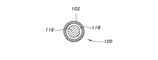
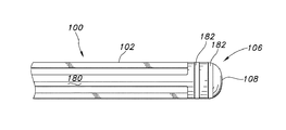
ここで図4を参照すると、エコー源性のカテーテル100は細長い管状部材102から構成され、細長い管状部材102は、近位端104、遠位端106、およびその遠位端におけるエコー源性カテーテル先端部108を有する。細長い管状部材102は、複数の出口孔112をその1つ以上の部分114に有する細長い管状部材102であってもよい。図5は、図4の線B−Bで切った細長い管状部材102の断面図であり、管状部材102内に配置された多孔質部材116を示す。環状空間118が、多孔質部材116と細長い管状部材102との間に存在し得る。あるいは、細長い管状部材102は、多孔質膜からなるものであり得る。
Referring now to FIG. 4, the
エコー源性のカテーテル先端部108は、カテーテル100の遠位端106の一部分であり得、高い音響インピーダンスを有するコバルトクロム、ガラス、水晶、結晶質の無機物または他の材料から形成され得る。他の典型的な材料として、ステンレス鋼を挙げることができる。図6に示すように、エコー源性のカテーテル先端部108は、支持体120を含み得る。エコー源性のカテーテル先端部108は、支持体120と一体的に形成され得るが、それに付着されてもよい。支持体120は、選択に応じてエコー源性であってもよい。一般的に、エコー源性のカテーテル先端部108は、図に示すように、支持体120のリブ122の外縁に合わせられたな直径を有する円形であり得る。
The
図7を参照すると、エコー源性のカテーテル先端部108の実施形態が示され、ここでは反射性の薄片130、反射性の球体132、および/または反射性の粒子136を材料の担体基質138に組み入れたものであり、担体基質の材料としては、シリコーンまたはカテーテル先端部108用に使うことができる他の適当で互換性のある医療グレードのプラスチックである。典型的な反射性の薄片130としては、金の薄片、銀の薄片等が挙げられる。反射性の球体132としては、金の球体、銀の球体、ガラスの球体等が挙げられる。反射性の粒子136としては、金の粒子、銀の粒子、ガラスの粒子等が挙げられる。
Referring to FIG. 7, an embodiment of an
あるいは、および/またはそれに加えて、エコー源性のカテーテル先端部108は、高程度のインピーダンスのミスマッチを作り出すべく遠位側の位置に担体基質に組み入れられた非常に高密度の材料を含むことができる。高程度なインピーダンスミスマッチを作り出すべく、高密度材料は、遠位側の位置においいて管状部材102に組み入れてもよい。
Alternatively and / or in addition, the
高密度材料を適切に選択することにより、先端部108および/または細長い管状部材102の一部分の音響インピーダンスと、周囲の組織の音響インピーダンスとの間に十分なレベルの差異を生じさせ、音響イメージングを利用して先端部108および/または細長い管状部材102の可視化を可能にするために十分な反射を生じさせることができる。
By appropriate selection of the high density material, a sufficient level of difference is produced between the acoustic impedance of the
比較的高密度な材料の1つのカテゴリーは、放射線不透過性材料である。これらの材料を、カテーテルまたは先端部を作るのに用いられるポリマーに加えられてもよい。放射線不透過性材料は、放射線を吸収および/または放射線が物体の通過するのを遮断する材料である。これらの材料としては、ヨウ素・バリウム材、ビスマス塩、タングステン、金、ハロゲン化部分、金属含有、光学的透過性ポリマー、およびそれらの混合物が挙げられる。 One category of relatively dense materials is radiopaque materials. These materials may be added to the polymer used to make the catheter or tip. A radiopaque material is a material that absorbs radiation and / or blocks radiation from passing through an object. These materials include iodine / barium materials, bismuth salts, tungsten, gold, halogenated moieties, metal-containing, optically transparent polymers, and mixtures thereof.
ハロゲン化ジオールやハロゲン化ジイソシアン酸エステル反応物などのハロゲン化部分は、放射線不透過性で、視覚的に透明であるという望ましい性質をもつポリウレタンを調製するために用いることができる。トランス−1,4−シクロヘキサンジイソシアネート(t−CHDI)を用いてポリウレタンを作製すると、放射線不透過性であるが、見た目が透明で毒物学的に無害な製品を作り出すことができることが見いだされている。このプロセスに関する詳細は、1993年1月20日公開のWagenerらによる欧州特許出願EP0523928A「Kink Resistant, Flexible, Radiopaque Polyurethane Tubing and Catheters Formed Therefrom」に記載されており、当該特許文献の内容は、ここで引用することにより本明細書の一部とする。 Halogenated moieties such as halogenated diols and halogenated diisocyanate reactants can be used to prepare polyurethanes with desirable properties of being radiopaque and visually transparent. It has been found that making polyurethane using trans-1,4-cyclohexane diisocyanate (t-CHDI) can create a radiopaque but transparent and toxicologically harmless product. . Details regarding this process are described in European Patent Application EP0523928A “Kink Resistant, Flexible, Radiopaque Polythane Tubing and Catheters Formed Therem” published by Wagener et al. It is made a part of this specification by quoting.
放射線不透過性添加物は、5〜60重量%の範囲の量で、より好ましくは10〜40重量%の範囲の量で、さらに望ましくは20〜30重量%の範囲の量で存在し得る。放射線不透過性添加物は、従来の方法で製造されるチューブの原料の高分子材料と混合されてもよく、例えば、硫酸バリウム粉末を、適切な重量%の添加量を含む樹脂ペレットを製造するべく押し出しによって混合してポリマーとしてもよい。 The radiopaque additive may be present in an amount ranging from 5 to 60% by weight, more preferably in an amount ranging from 10 to 40% by weight, and even more desirably in an amount ranging from 20 to 30% by weight. The radiopaque additive may be mixed with the tube raw polymer material produced by conventional methods, for example, barium sulfate powder to produce resin pellets with appropriate weight percent additions. The polymer may be mixed by extrusion as much as possible.
高密度材料が、音響イメージングの中のコントラストを与えるためのセグメントに結合されるか、そこで利用されることも想定されている。例えば、バンドまたはセグメントが、放射線不透過性添加物を含まないかほとんど含まないこともあり得るが、バンドまたはセグメントが、放射線不透過性添加物をほとんど含まない他の部分より少なくとも5〜10重量%多く含むこともある。両タイプのバンドまたはセグメントが、種類および/または量の異なる放射線不透過性材料を含み、この結果、密度の異なるバンドまたはセグメントとなる場合(例えば、タングステンが用いられるバンドまたはセグメントと、硫酸バリウムが用いられるバンドまたはセグメントが混在する場合)も想定されている。この密度の差異により、音響インピーダンスの差に基づいて音響イメージングを利用してバンドまたはセグメントの位置を認識することが可能となる。 It is also envisioned that a high density material is coupled to or utilized in a segment for providing contrast in acoustic imaging. For example, the band or segment may contain little or no radiopaque additive, but the band or segment is at least 5 to 10 weights over other parts that contain little radiopaque additive. % May be included. Where both types of bands or segments contain different types and / or amounts of radiopaque materials resulting in bands or segments of different densities (eg, bands or segments in which tungsten is used and barium sulfate is It is also assumed that the bands or segments used are mixed). Due to this difference in density, it becomes possible to recognize the position of the band or segment using acoustic imaging based on the difference in acoustic impedance.
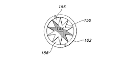
あるいは、および/またはそれに加えて、エコー源性のカテーテル先端部は、高い音響インピーダンスを有するコバルトクロム、ガラス、水晶、結晶質の無機物または他の材料から形成されるか、それで被覆されているエコー源性の挿入物またはプラグ150であるか、そのような挿入物またはプラグ150を含み得る。図8を参照すると、エコー源性カテーテル100は、エコー源性挿入物またはプラグ150を組み入れたものであり得、そのような挿入物を組み入れたカテーテルの先端部または他の部分(他の複数の部分)が、音響イメージング中に可視化されるような効果的な量の音波を反射する形状または構成を有するようなものとされている。つまり、エコー源性材料またはエコー源性コーティングを有する適切な形状または構成の組み合わせは、挿入物またはプラグの音響反射性を大幅に向上させるものと考えられる。適切な形状としては、ギア形状(例えば、複数の平坦な反射面を提供する溝、ノッチ、および/または小鈍鋸歯形状部を備えた円形や円筒形の形状)、球面形、多角形を連結することによって形成される多面的な幾何学的形状(例えば、測地線形状)等が挙げられる。図9は、図8の線C−Cで切った細長い管状部材102の断面図であり、細長い部材102の内部にエコー源性挿入物またはプラグ150が配置されているところが示されている。図9にみられるように、エコー源性挿入物またはプラグ150は、軸部またはコア領域154から径方向外向きに延びる棘条152によって形成された「星」形状の断面を有し、これによりエコー源性挿入物150における一連の溝156が形成される。
Alternatively and / or in addition, the echogenic catheter tip may be made of or coated with cobalt chrome, glass, quartz, crystalline inorganics or other materials having high acoustic impedance. A source insert or plug 150 or may include such an insert or plug 150 . Referring to FIG. 8, the
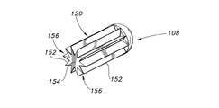
図10は、そのような特徴が、カテーテル先端部の少なくとも一部分がエコー源性であるように図6に示すタイプのカテーテル先端部108にいかにして組み入れられるかを示す。すなわち、カテーテル先端部、支持体またはその両方が、エコー源性である場合がある。カテーテル先端部108は、カテーテル先端部と一体的に形成され得るが、それに付着されてもよい支持体120を含む。支持体120は、音響反射性の材料でできているか、そのような材料で被覆され、音響反射性の形状を有するように構成されている点を除いて、基本的に図6に示すものと同様であり得る。例えば、支持体は図8および図9に示すエコー源性の挿入物と類似の幾何学的形状を有し得る。図10を参照すると、支持体120が、軸部またはコア領域154から径方向外向きに延びる上記の棘条152によって形成された「星」形状の断面を有し、これにより一連の溝156が形成される。つまり、カテーテル先端部はそれ自身がエコー源性である場合、および/またはエコー源性である支持体を含む場合がある。
FIG. 10 illustrates how such features can be incorporated into a
図11は、図8の線C−Cで切った細長い管状部材102の断面図であり、管状部材102の内部に配置された、別の種類の例示的な細長いエコー源性挿入物またはプラグ150が示されている。図11でわかるように、エコー源性挿入物またはプラグ150は、軸部またはコア領域154から径方向外向きに延びる突出部158によって形成された「ギア」形状または小鈍鋸歯形状の断面を有し、これにより一連のノッチ160が形成される。
FIG. 11 is a cross-sectional view of the
図12Aは、カテーテル先端部の少なくとも一部分がエコー源性であるように、図6に示すタイプのカテーテル先端部108に組み入れられた特徴の別の例である。このカテーテル先端部108は、カテーテル先端部と一体的に形成され得るが、それに付着結合されてもよい支持体120を含む。この例では、支持体120は、図11に示されるエコー源性の挿入物と概ね同様で、軸部またはコア領域154から径方向外向きに延びる突出部158によって形成された「ギア」形状または小鈍鋸歯形状の断面を有し、これにより一連のノッチ160が形成される。
FIG. 12A is another example of features incorporated into a
図12Bは、カテーテル先端部と一体的に形成され得る支持体120を備える、他の例示的なカテーテル先端部108を示す。支持体は管状部材102の内部に配置され、接着剤により、摩擦による嵌合により、または他の機械的締結手段によって固定することができる。本カテーテル先端部は、「砂時計」形状部と、小鈍鋸歯形状部または他の複雑な幾何学的形状のない表面とを有する。図12Cは、カテーテル先端部と一体的に形成され得る支持体120を備える他の例示的なカテーテル先端部108を示す。支持体は管状部材102の内部に配置され、接着剤により、摩擦による嵌合により、または他の機械的締結手段によって固定することができる。本カテーテル先端部は、「弾丸」形状部と、小鈍鋸歯形状部または他の複雑な幾何学的形状のない表面とを有する。これらの比較的単純な形状は望ましくはステンレス鋼で形成されるが、高い音響インピーダンスを有する他の材料として、これらに限定されないが、コバルトクロム、ガラス、または水晶などが使用できる。
FIG. 12B shows another
図8、図9および図11に概略が図示されているように、エコー源性の挿入物(または支持体)の鋭いおよび/または平らな端部を、細長い管状部材102によって画定されるルーメンの壁に係合させ、エコー源性の挿入物(またはエコー源性のカテーテル先端部)が細長い管状部材に対して動くのを防止することができる。
As shown schematically in FIGS. 8, 9 and 11, the sharp and / or flat end of the echogenic insert (or support) is shown in the lumen defined by the
別形態としては、図13Aを参照すると、エコー源性のカテーテル100が、細長い管状部材102の内部に配置されたエコー源性の挿入物またはプラグ150を組み入れることができる。エコー源性の挿入物またはプラグ150は、ガラス、水晶、または類似の材料から形成することができ、概ね円筒形状または構成を有し、かつ音響イメージングを用いて可視化できる密度の差異を生成するべく材料を貫通する1つ以上のチューブまたは円筒形のチャネル170を備える。図13Bは、図13Aに示すエコー源性のカテーテルの、線D−Dに沿って切った横断面図である。図13Bに示すように、管状部材102は、円筒形の横断面を有し、音響イメージングを用いて可視化できる密度の差異を生成するべく材料を貫通する1つ以上のチューブまたは円筒形のチャンネル170を備えるエコー源性挿入物150を組み入れている。
Alternatively, referring to FIG. 13A, an
本発明の一態様では、図14Aに示すように、エコー源性のカテーテル100は、細長い管状部材102の内部に配置された球体であるか球形状を有するエコー源性のビード172を備えることができる。エコー源性のビード172は、ガラス、水晶、または類似した材料で形成されたものでよいが、任意の従来の非エコー源性の材料からなるもので、エコー源性のコーティングを備えたものでもよい。エコー源性のビードは複数の凹部174を備え、音響イメージングを用いた場合の可視性を向上させるために、皺形状またはひだ形状を更に有していてもよい。図14Bは、凹部としわ形状を強調して示したエコー源性のビード172の詳細を示す斜視図である。
In one aspect of the present invention, as shown in FIG. 14A, the
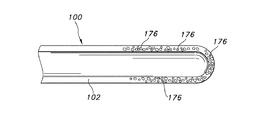
図15Aは、細長い管状部材102に形成された空隙または泡状部176を示す、例示的なエコー源性カテーテル100の断面図である。これらの空隙または泡状部は、カテーテルの製造中に生成される。空隙または泡状部は、押し出し加工によりカテーテルに形成されるポリマーにガスを導入することによって形成することができる。空隙または泡状部は、押し出し法により、ガス発生物質とポリマーとを混合することにより、または、他の従来の技術によって形成することもできる。望ましくは、空隙または泡状部176は、図15Bに示すように細長い管状部材102の材料に存在し、細長い管状部材の表面には存在しない。高分子物質の空隙または泡状部が、音響イメージングによる視覚化を可能とする高程度のインピーダンスミスマッチを提供することができると一般的に考えられている。さらにインピーダンスミスマッチの程度を向上させるべくポリマーの密度を増加させるために、いくつかの材料をポリマーと混合させることも想定されている。そのような材料の典型的なものとしては、放射線不透過性材を挙げることができる。
FIG. 15A is a cross-sectional view of an exemplary
図16Aは、その遠位端106に、シャフト180を有するエコー源性カテーテル先端部108を備えたエコー源性カテーテル100の細長い管状部材102を示す図である。カテーテル先端部108は先に述べたように通常はエコー源性に形成することができるが、さらにエコー源性の材料のバンド182を備えていてもよい。バンドは、ガラス、水晶、または他のエコー源性材料からなり得ることが想定されている。バンドが音響イメージングによる視覚化を可能とする高度なインピーダンスミスマッチのある材料とすることも想定されている。図16Bは、音響イメージングによる視覚化を可能とするエコー源性の材料または高度なインピーダンスミスマッチのある材料のバンドまたは挿入物182を備えるシャフト180を有するエコー源性のカテーテル先端部108の詳細を示す図である。
FIG. 16A shows the elongate
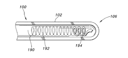
本発明の一態様によれば、カテーテル100が、細長い管状部材102の内部に金属ばね190を備え得る。一般的に、金属ばね190は、キンク耐性を与えるために用いられ得る。金属ばね190は、その音響インピーダンスを高めるために改変されてもよい。この改変は、図17Bに示す金属ばね190の概ね丸い断面192を、図17Cに示すような概ね平らな断面194に変えることによって達成することができる。この概ね平らな断面194は、金属ばねのいくつかの部分または互い違いな領域に設けられてよく、および/またはカテーテルの遠位端106に配置されてもよい。金属ばね190は、音響イメージングによって可視化される音波を生成するのに十分な周波数でばねを振動させるトランスデューサに接続させることによって、能動的にエコー源性にし得ることも想定されている。そのようなトランスデューサは、例えば圧電変換器であり得る。他のタイプのトランスデューサとしては、磁気歪変換器や電磁変換器が挙げられ、あるいはレーザーで起動する要素を用いることもできる。
In accordance with one aspect of the present invention, the
カテーテル100は、取り外し可能なエコー源性のガイドワイヤ200をカテーテルに組み入れることによってエコー源性とすることができる。ガイドワイヤ200は、エコー源性の材料から形成されているため、またはエコー源性のコーティングが被覆されているため、エコー源性であり得る。あるいは、および/またはそれに加えて、エコー源性のガイドワイヤ先端部202を、エコー源性のガイドワイヤ200に付加することもできる。ガイドワイヤ200が、受動的にエコー源性となるように、エコー源性の材料から形成されたものか、エコー源性のコーティングを塗布された撚り線または追加のワイヤ204を含み得ることも想定されている。撚り線または追加のワイヤは、トランスデューサとの接続により振動するように構成されていてもよい。
The
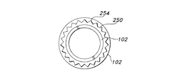
カテーテルは、1つ以上の金属のバンドまたはリングで製造されることが多い。本発明の一態様では、そのような金属バンドまたはリングは、エコー源性となるように改変され得る。図19を参照すると、複数の出口開口112を有する例示的なカテーテル100であって、カテーテル遠位端106の近傍に配置された第1の金属バンド250と、第2の金属バンド252とを備える、該カテーテル100が示されている。図19および図20を参照すると、バンドは、細長い管状部材102から径方向外向きに突出する棘条、突出部、円鋸歯状物等254を形成するものと記述され得る断面を有し得る。突出部254は、細長い管状部材102の径方向に最外部の表面から外側に突出しないようにカテーテル内に包入されている点に留意されたい。あるいは、および/またはそれに加えて、金属バンドは、音響イメージング技術による視覚化をより強化するために、溝、凹部、クロスハッチング等を備えていてもよい。
Catheter is often made of one or more metal bands or rings. In one aspect of the invention, such a metal band or ring can be modified to be echogenic. Referring to FIG. 19, an
本発明のある態様では、カテーテルの金属バンド、複数の金属バンド、および/または任意のエコー源性構成部品が、カテーテルに関する情報を提供するように構成され得る。望ましくは、その情報は音響イメージングの間に提供され、エコー源性構成部品の強度または配置(またはその組合せ)に基づいて解釈される。発明の別の態様によれば、他の人間(例えば、医療専門家)が情報を解釈できるようにするために、1つ以上のチャートまたは他のツールが設けられ得る。あるいは、および/またはそれに加えて、音響イメージングの間に提供されるイメージが、音響イメージング装置で解釈されてもよい。提供され得るカテーテルに関する情報の例としては、以下に限定されないが、出口開口配置、出口開口密度、長さ、直径(他のサイズ情報)、カテーテルの先端部が開放されているか否か、カテーテルの先端部が閉鎖させているか否か、等が挙げられる。 In certain aspects of the invention, the metal band, multiple metal bands, and / or any echogenic component of the catheter may be configured to provide information about the catheter. Desirably, the information is provided during acoustic imaging and is interpreted based on the strength or placement (or combination thereof) of the echogenic components. In accordance with another aspect of the invention, one or more charts or other tools may be provided to allow other persons (eg, medical professionals) to interpret the information. Alternatively and / or in addition, images provided during acoustic imaging may be interpreted with an acoustic imaging device. Examples of information about catheters that may be provided include, but are not limited to, outlet opening configuration, outlet opening density, length, diameter (other size information), whether the catheter tip is open, Whether or not the tip is closed is mentioned.
カテーテル100の細長い管状部材102は、その内部または外部表面に、音響インピーダンスを増加させる材料を被覆することによってエコー源性にしたものでもよい。例示的な材料としては、炭化チタン、窒化チタン、チタン窒化アルミニウム、炭窒化チタンアルミニウムなどが挙げられる。ガラスやアクリルガラス(ポリ(メチルメタクリレート)とも称する)のような硬質で密なアモルファス非晶質固体や、2006年6月29日に公開されたJanssenらによる米国特許出願第2006/0141186号「Gloves With Hydrogel Coating For Damp Hand Donning and Method of Making Same」に記載されている硬質でガラス質のヒドロゲルも使用することができる。
The elongate
コーティングは細長い管状部材の外側に設けられても、あるいは細長い管状部材の内部に設けられてもよい。本発明のいくつかの態様では、細長い管状部材の内部のコーティングは、音響的に反射する粒子を担体に組み入れたコーティングであり得る。例えば、そのようなコーティングは、ガラスまたは他の音響的に反射する材料の球形ビードを含むものであって、球形ビードが、それを細長い管状部材の内面に結びつける担体に含められたものであり得る。 The coating may be provided on the outside of the elongate tubular member or may be provided on the inside of the elongate tubular member. In some aspects of the invention, the coating inside the elongate tubular member can be a coating that incorporates acoustically reflective particles into the carrier. For example, such a coating may include a spherical bead of glass or other acoustically reflective material that is included in a carrier that ties it to the inner surface of an elongated tubular member. .
あるいは、および/またはそれに加えて、細長い管状部材(および/またはカテーテル先端部)は、例えば2003年1月14日にJonesらに付与された米国特許第6,506,156号「Echogenic Coating」に記載のもの、2007年6月12日にViolanteらに付与された米国特許7,229,413号「Echogenic Coatings With Overcoat」に記載のもの、および2009年12月24日に出願されたThurmond, IIらによる米国特許出願2009/0318746号「Lubricious Echogenic Coatings」に記載のもののような種々の既知のエコー源性コーティングによってエコー源性にされたものであり得る。本発明の別の態様によれば、カテーテルの細長い管状部材は、その音響インピーダンスを増加させる構成部品を内部に含めることによってエコー源性にされたものであり得る。そのような内部の構成部品は、管状部材の内部に包入されたエコー源性の金属ワイヤまたは細長い管状コイルばねでさえある場合がある。細長い管状コイルばねは、エコー源性の材料から形成されたもの、音響インピーダンスを増加させる材料で被覆されたもの、または音響インピーダンスを増加させるための溝、回折格子、凹部等で改変された表面を持つものであり得る。 Alternatively and / or in addition, elongate tubular members (and / or catheter tips) are described, for example, in US Pat. No. 6,506,156 “Echogenic Coating” issued to Jones et al. US Pat. No. 7,229,413 granted to Violante et al. On June 12, 2007, “Echogenic Coatings with Overcoat”, and Thurmond, II filed on December 24, 2009. Can be rendered echogenic by various known echogenic coatings, such as those described in US Patent Application No. 2009/0318746 by Lubricous Echogenic Coatings. According to another aspect of the present invention, the elongated tubular member of the catheter may be those that are in the echogenic by the this include components to increase its acoustic impedance inside. Such internal components may even be echogenic metal wires or elongated tubular coil springs encased within the tubular member. An elongate tubular coil spring is formed from an echogenic material, coated with a material that increases acoustic impedance, or a surface modified with grooves, diffraction gratings, recesses, etc. to increase acoustic impedance. Can have.
あるいは、および/またはそれに加えて、内部の構成部品は、音響イメージングの間に可視化される音波を能動的に生成する構成部品であり得る。そのような構成部品は、エネルギー源を含むものかエネルギー源に接続されたものであり、トランスデューサ(例えばエネルギーを音波に変換する圧電変換器)をさらに含むものであり得る。磁気歪変換器、電磁変換器、またはレーザーによって駆動される要素を含む他のタイプのトランスデューサも使用され得る。 Alternatively and / or in addition, the internal components can be components that actively generate acoustic waves that are visualized during acoustic imaging. Such components may include or be connected to an energy source and may further include a transducer (eg, a piezoelectric transducer that converts energy into sound waves). Other types of transducers including magnetostrictive transducers, electromagnetic transducers, or elements driven by lasers may also be used.
細長い管状部材が、その一部分に複数の出口開口またはスロットを備えた細長いチューブであり、細長い多孔質部材がチューブの内部に配置された実施形態において、細長い多孔質部材が、音響インピーダンスを増加させる材料から作られるか、そのような材料を含み得ることが想定されている。そのような多孔質複合材料の例としては、ガラスまたは他の音響反射性材料の球形ビード、気泡を長さ方向に沿って混入させた熱可塑性ポリマー繊維から形成される原綿またはウェブ、ガス充填クローズドセルが内部に分散された、ポリマー網からなる多孔性マトリックス、または類似の構造が挙げられる。気泡を長さ方向に沿って混入させた熱可塑性ポリマー繊維から形成される原綿またはウェブの例は、2002年5月28日にJamesonに付与された米国特許第6,395,215号「Method and Apparatus for Ultrasonically Assisted Melt Extrusion of Fibers」に記載されており、この文献の内容は、引用により本明細書の一部とする。ガス充填クローズドセルが内部に分散された、ポリマー網からなる多孔性マトリックスまたは類似の構造の例は、2007年1月9日にGibbinsらに付与された米国特許第7,160,553号「Matrix for Oxygen Deliver to Compromised Tissues」に記載されており、この文献の内容は、引用により本明細書の一部とする。 In embodiments in which the elongate tubular member is an elongate tube with a plurality of outlet openings or slots in a portion thereof and the elongate porous member is disposed within the tube, the elongate porous member is a material that increases acoustic impedance. It is envisioned that it may be made from or contain such materials. Examples of such porous composites include spherical beads of glass or other acoustically reflective material, raw cotton or web formed from thermoplastic polymer fibers mixed with bubbles along the length, gas filled closed A porous matrix consisting of a polymer network, or similar structure, in which the cells are dispersed. Examples of raw cotton or webs formed from thermoplastic polymer fibers mixed with air bubbles along their length are described in US Pat. No. 6,395,215, “Method and,” issued to Jameson on May 28, 2002. "Apparatus for Ultrasonically Assisted Melt Extraction of Fibers", the contents of which are hereby incorporated by reference. An example of a porous matrix or similar structure consisting of a polymer network with a gas-filled closed cell dispersed therein is described in US Pat. No. 7,160,553 “Matrix” granted to Gibbins et al. for Oxygen Deliverer to Promised Tissues, the contents of which are hereby incorporated by reference.
本発明は、神経ブロック処置を実行するための装置を包含する。その装置は、前述のようなエコー源性のニードルと、前述のように制御された薬物の送達を行うべく構成されたエコー源性のカテーテルとからなる。前記装置は、エコー源性のシースをさらに含み得る。例示的なエコー源性シースは、2009年1月1日公開のFernaldによる米国特許出願第2009/0005774号に記載されており、この文献の内容は、引用により本明細書の一部とする。そのようなエコー源性のシースは、上述の材料、技術またはそれらの組合せのいずれかによってエコー源性とされたものであり得る。しかし、シースがガイダンス処置において助けとなり、ニードルを抜いた後シースの配置を超音波で確認するためのシースをエコー源性にすることも、望ましいことであり得る。これに関連して、シースは、シース自体に混入されるか後でシースの表面に塗布された任意のエコー源性材料(例えば、金属の糸や薄片)を含むものでもよい。別の実施形態において、シースは、単にシースを貫通する開口または穿孔を画定し、超音波イメージング中にその穿孔を通して金属の針が露出されるようにすることによっても、効果的にエコー源性にすることができる。シースを通してニードルの軸線上の一点または一部を検出することによって、シースの位置を確かめることもできる。 The present invention includes an apparatus for performing a nerve block procedure. The device consists of an echogenic needle as described above and an echogenic catheter configured for controlled drug delivery as described above. The apparatus may further include an echogenic sheath. An exemplary echogenic sheath is described in US Patent Application No. 2009/0005774 by Fernald, published Jan. 1, 2009, the contents of which are hereby incorporated by reference. Such echogenic sheaths can be made echogenic by any of the materials, techniques, or combinations thereof described above. However, it may also be desirable to make the sheath echogenic to confirm the placement of the sheath with ultrasound after withdrawal of the needle, as the sheath helps in the guidance procedure. In this regard, the sheath may include any echogenic material (eg, metal thread or flake) that is incorporated into the sheath itself or later applied to the surface of the sheath. In another embodiment, the sheath is also effectively echogenic by simply defining an opening or perforation through the sheath and allowing a metal needle to be exposed through the perforation during ultrasound imaging. can do. The position of the sheath can also be ascertained by detecting a point or portion on the needle axis through the sheath.
本発明は、神経ブロック処置を実行するためのシステムを包含する。そのシステムは、神経束の領域に上述のようなエコー源性ニードルを導入すること、音波イメージングを利用して前記神経束に隣接するところに前記エコー源性ニードルを位置させること、前記エコー源性ニードルを通して前述のように制御された流体の送達を行うべく構成されたエコー源性カテーテルを導入すること、前記エコー源性ニードルを引き抜くこと、音波イメージングを利用して前記神経束に隣接するところに前記エコー源性カテーテルを位置させること、および前記エコー源性カテーテルを通して前記神経束に対して流体の送達を行うことを含む。 The present invention includes a system for performing a nerve block procedure. The system introduces an echogenic needle as described above into the area of the nerve bundle, positions the echogenic needle adjacent to the nerve bundle using acoustic imaging, the echogenic needle Introducing an echogenic catheter configured for controlled fluid delivery through the needle, withdrawing the echogenic needle, and adjacent to the nerve bundle using acoustic imaging; Positioning the echogenic catheter and delivering fluid to the nerve bundle through the echogenic catheter.
神経ブロック処置を行うための上述のシステムは、さらに、前記神経束に隣接するところに前記エコー源性ニードルを位置させる前に前記エコー源性ニードルの上にシースをかぶせること、前記シースをかぶせた状態にしたまま前記エコー源性ニードルを引き抜くこと、および前記エコー源性カテーテルを前記シースを通して押し込むことを含み得る。シースは、前に概説されたようにエコー源性であり得る。 The above-described system for performing a nerve block procedure further includes placing a sheath over the echogenic needle prior to positioning the echogenic needle adjacent to the nerve bundle. Pulling out the echogenic needle while in a state and pushing the echogenic catheter through the sheath may be included. The sheath can be echogenic as outlined previously.
本発明は、神経ブロック処置を行うための別の装置を包含する。この装置は、患者にカテーテルを配置するための皮下経路を形成するための、エコー源性軟組織トンネリングデバイスと、制御された薬物の送達を行うべく構成されたエコー源性カテーテルとを備える。 The present invention includes another apparatus for performing a nerve block procedure. The apparatus comprises an echogenic soft tissue tunneling device for creating a subcutaneous pathway for placement of the catheter in a patient and an echogenic catheter configured for controlled drug delivery.
例示的な軟組織トンネリングデバイスは、例えば2008年4月10日公開のMassengaleによる米国特許出願第2008/0086161号「Soft Tissue Tunneling Device」、および2008年12月18日公開のMassengaleによる米国特許出願第2008/0312677号「Soft Tissue Tunneling Device」などに記載されており、これらの文献の内容は、引用により本明細書の一部とする。 Exemplary soft tissue tunneling devices include, for example, US Patent Application No. 2008/0086161 “Soft Tissue Tunneling Device” published by Massengale published on Apr. 10, 2008, and US Patent Application No. 2008 issued by Massengale published Dec. 18, 2008. No. 0312677, “Soft Tissue Tunneling Device” and the like, the contents of these documents are hereby incorporated by reference.
例えば、これらの軟組織トンネリングデバイスは、丸い遠位端を有する、細長いシャフトを含む。この遠位端および/または細長いシャフトは、上述のエコー源性ニードルおよび/またはカテーテルと同様の方法でエコー源性にされ得る。これらのデバイスは、トンネリングデバイスのユーザが、前記トンネリングデバイスを操作できるようにするべく構成された、前記シャフトに固定されたハンドルをさらに備え得る。細長いシャフトは、トンネリングデバイスの使用前にその形状を変化させられるような柔軟性を有するものであり得る。例えば、シャフトは、限定されないが湾曲した形状などの非直線的な形状を有し得る。 For example, these soft tissue tunneling devices include an elongate shaft having a rounded distal end. This distal end and / or elongate shaft may be rendered echogenic in a manner similar to the echogenic needle and / or catheter described above. These devices may further comprise a handle secured to the shaft configured to allow a user of the tunneling device to operate the tunneling device. The elongate shaft can be flexible such that its shape can be changed prior to use of the tunneling device. For example, the shaft may have a non-linear shape such as but not limited to a curved shape.
本発明の装置はさらに、シャフトの一部の上に配置可能なシースを備える。このシースは、前記シースと前記シャフトとが一体となって患者の体内を進むことができるような前記シャフトとぴったり合うサイズを有する。本発明によれば、細長いシャフトとシースの少なくとも一方はエコー源性である。すなわち、組織トンネリングデバイスの細長いシャフトがエコー源性である場合、シースがエコー源性である場合、あるいは両方ともエコー源性である場合がある。 The device of the present invention further comprises a sheath positionable over a portion of the shaft. The sheath has a size that fits the shaft so that the sheath and the shaft can be integrated into the patient's body. According to the present invention, at least one of the elongated shaft and the sheath is echogenic. That is, the elongate shaft of the tissue tunneling device may be echogenic, the sheath may be echogenic, or both may be echogenic.
神経ブロック処置を行うための装置のある態様によれば、エコー源性の軟組織トンネリングデバイスの細長いシャフトは、内部ルーメンを画定し得る。加えて、トンネリングデバイスは、前記シャフトとの長さ方向に沿って配置され、前記内部ルーメンから前記シャフトの外部に貫通する少なくとも1つの流体出口開口と、液体を、前記内部ルーメン内に導入し、前記少なくとも1つの出口開口を通して前記患者に投与できるようにする前記内部ルーメンへの入口とを含み得る。前記装置はさらに、細長いシャフトの上に摺動自在に配置されたシースであって、細長いシャフトとシースの少なくとも一方がエコー源性である、該シースを備え得る。 According to certain aspects of an apparatus for performing a nerve block procedure, an elongate shaft of an echogenic soft tissue tunneling device may define an internal lumen. In addition, a tunneling device is disposed along the length of the shaft, introduces at least one fluid outlet opening extending from the inner lumen to the exterior of the shaft, and liquid into the inner lumen; And an inlet to the internal lumen that allows administration to the patient through the at least one outlet opening. The apparatus further includes a slidably arranged sheath over the elongate shaft, at least one of which is echogenic elongate shaft and Sea scan may comprise the sheath.
本発明の別の態様では、前記トンネリングデバイスが、前記シャフトの前記遠位端に配置された格納可能なニードルをさらに含む。前記格納可能なニードルは、患者の身体にトンネリングデバイスを進める前に穿刺する際の助けとするために用いることができる。前記格納可能なニードルは、ニードルルーメンの遠位端の内部に収容することができ、前記細長いシャフトが実質的に丸い遠位端を維持するように前記ニードルルーメン内に完全に収容することが可能である。前記格納可能なニードルのニードルルーメン内での位置は、任意の方法を用いて変えることが可能である。 In another aspect of the invention, the tunneling device further comprises a retractable needle disposed at the distal end of the shaft. The retractable needle can be used to assist in puncturing the patient's body before a tunneling device is advanced. The retractable needle can be received within the distal end of the needle lumen and can be fully received within the needle lumen such that the elongate shaft maintains a substantially rounded distal end. It is. The position of the retractable needle within the needle lumen can be changed using any method.
本発明は、上述のエコー源性の軟組織トンネリングデバイスを利用した神経ブロック処置を行うためのシステムも包含する。一般的に、このシステムは、(i)患者にカテーテルを入れるための皮下経路を形成するためのエコー源性軟組織トンネリングデバイスのハンドルを把持する過程であって、前記トンネリングデバイスは、丸い遠位端を有し、かつ内部ルーメンを画定している細長いシャフトと、前記内部ルーメンから前記シャフトの外部に貫通する少なくとも1つの流体出口開口とを有する、該過程と、(ii)患者の体内の神経束の領域に前記エコー源性トンネリングデバイスを導入する過程と、(iii)音波イメージング技法を利用して前記神経束に隣接するところに前記エコー源性トンネリングデバイスを位置させる過程と、(iv)前記エコー源性トンネリングデバイスを引き抜く過程と、(v)前記エコー源性トンネリングデバイスによって形成された皮下経路を通して、流体の制御された送達を行うべく構成されたエコー源性カテーテルを導入する過程と、(vi)波イメージング技法を利用して前記神経束に隣接するところにエコー源性カテーテルを位置させる過程と、(vi)前記エコー源性カテーテルを通して前記神経束に流体を送達する過程とを含む。 The present invention also includes a system for performing nerve block treatment utilizing the above-described echogenic soft tissue tunneling device. In general, this system is a process of (i) grasping a handle of an echogenic soft tissue tunneling device to form a subcutaneous path for placing a catheter in a patient, the tunneling device comprising a round distal end And (ii) a nerve bundle in the patient's body, comprising: an elongated shaft having an inner lumen defining at least one fluid outlet opening extending from the inner lumen to the exterior of the shaft; Introducing the echogenic tunneling device into a region of: (iii) locating the echogenic tunneling device adjacent to the nerve bundle using acoustic imaging techniques; and (iv) the echo A process of withdrawing the source tunneling device; (v) shaped by the echo source tunneling device; Introducing an echogenic catheter configured to provide controlled delivery of fluid through a defined subcutaneous route, and (vi) utilizing an imaging technique to place the echogenic catheter adjacent to the nerve bundle And (vi) delivering fluid to the nerve bundle through the echogenic catheter.
当該システムの一態様では、エコー源性のトンネリングデバイスがシャフトの一部を摺動可能に外囲するシースを更に含み得、それによって前記システムは、(a)前記トンネリングデバイスの導入と位置づけとともに前記シースの導入し、前進させる過程と、(b)前記シースから前記シャフトの引き抜き、前記シースを体内に残す過程とをさらに含む。当該システムでそのようなシースが利用される場合、前記トンネリングデバイスと前記シースの少なくとも一方はエコー源性であるべきである。 In one aspect of the system, the echogenic tunneling device may further include a sheath that slidably surrounds a portion of the shaft, whereby the system includes (a) the introduction and positioning of the tunneling device A step of introducing and advancing the sheath; and (b) a step of withdrawing the shaft from the sheath and leaving the sheath in the body. If such a sheath is utilized in the system, at least one of the tunneling device and the sheath should be echogenic.
本明細書中で引用により種々の特許文献の内容が編入され、それらの編入された内容は本明細書の記載内容との間で不整合がある場合があるが、そのときは明細書の記載内容が基準となる。加えて本開示は、特定の実施形態について詳細に説明されているが、本開示の精神および範囲を逸脱することなく種々の改変、修正、および変更が本開示に対してなされ得ることは、当業者には明らかであろう。したがって、特許請求の範囲の請求項に包含されるあらゆるそのような改変、修正、および変更は、請求項の範囲に包含される。 The contents of various patent documents are incorporated by reference in the present specification, and the incorporated contents may be inconsistent with the description of the present specification. The content is the standard. In addition, while the present disclosure has been described in detail with reference to specific embodiments, it should be understood that various changes, modifications, and changes may be made to the disclosure without departing from the spirit and scope of the disclosure. It will be clear to the contractor. Accordingly, all such changes, modifications, and changes that fall within the scope of the claims are encompassed within the scope of the claims.
Claims (13)
細長い管状部材と、
エコー源性カテーテル先端部とを備え、
前記エコー源性カテーテル先端部は、前記細長い管状部材に挿入される支持体を備えるエコー源性挿入物またはプラグを含み、
前記支持体は、音響反射性の材料から形成されるか、音響反射性の材料で被覆され、かつ軸部から径方向外向きに延びて一連の溝を画定する複数の凸部を含み、
前記複数の凸部は、(i)複数の棘条であって、各棘条の前記支持体の長手方向に垂直な断面の形状が、径方向外側に先端を有する三角形である、該複数の突条か、または(ii)複数の突出部であって、各突出部の前記支持体の長手方向に垂直な断面の形状が、径方向外側縁部の長さが内側縁部の長さより長い環状扇形または逆台形である、該複数の突出部であることを特徴とするエコー源性カテーテル。 An echogenic catheter configured for controlled fluid delivery across an anatomical region, comprising:
An elongated tubular member;
An echogenic catheter tip,
The echogenic catheter tip comprises an echogenic insert or plug comprising a support inserted into the elongate tubular member;
The support is either formed from the acoustic reflective material is coated with a sound reflective material, and extends from the shaft portion radially outwardly seen including a plurality of protrusions defining a series of grooves,
The plurality of convex portions are (i) a plurality of spines, and the shape of a cross section perpendicular to the longitudinal direction of the support of each spine is a triangle having a distal end radially outward. A protrusion, or (ii) a plurality of protrusions, each having a cross-sectional shape perpendicular to the longitudinal direction of the support, wherein the length of the radially outer edge is longer than the length of the inner edge An echogenic catheter , wherein the plurality of protrusions are annular sectors or inverted trapezoids .
エコー源性ニードルと、
請求項1〜7のいずれかに記載のエコー源性カテーテルとを備えることを特徴とする装置。 An apparatus for performing a nerve block treatment,
An echogenic needle;
Device characterized in that it comprises a echogenic catheter according to any one of claims 1-7.
請求項1〜7のいずれかに記載のエコー源性カテーテルとを備え、
前記流体が薬液であることを特徴とする装置。 An apparatus for performing a nerve block procedure, the echogenic soft tissue tunneling device for forming a subcutaneous path for placing a catheter in a patient;
The echogenic catheter according to any one of claims 1 to 7 ,
An apparatus characterized in that the fluid is a chemical solution.
丸い遠位端を有する、細長いシャフトと、
前記トンネリングデバイスのユーザが、前記トンネリングデバイスを操作できるようにするべく構成された、前記シャフトに固定されたハンドルと、
前記シャフトの一部にかぶせることが可能なシースであって、前記シースと前記シャフトとが一体となって患者の体内を進むことができるような前記シャフトとぴったり合うサイズを有する、該シースとを含むことを特徴とする請求項10に記載の装置。 The echogenic soft tissue tunneling device comprises:
An elongate shaft having a rounded distal end;
A handle secured to the shaft configured to allow a user of the tunneling device to operate the tunneling device;
A sheath that can be placed over a portion of the shaft, the sheath and the shaft having a size that fits the shaft so that the shaft and the shaft can travel together in a patient. The apparatus of claim 10 , comprising:
前記エコー源性軟組織トンネリングデバイスが、
前記シャフトとの長さ方向に沿って配置され、前記内部ルーメンから前記シャフトの外部に貫通する少なくとも1つの流体出口開口と、
液体を、前記内部ルーメン内に導入し、前記少なくとも1つの出口開口を通して前記患者に投与できるようにする前記内部ルーメンへの入口とを含むことを特徴とする請求項11に記載の装置。 The elongated shaft defines an internal lumen;
The echogenic soft tissue tunneling device comprises:
At least one fluid outlet opening disposed along the length of the shaft and extending from the inner lumen to the exterior of the shaft;
12. The apparatus of claim 11 , including an inlet to the inner lumen that allows liquid to be introduced into the inner lumen and administered to the patient through the at least one outlet opening.
Applications Claiming Priority (5)
| Application Number | Priority Date | Filing Date | Title |
|---|---|---|---|
| US39404010P | 2010-10-18 | 2010-10-18 | |
| US61/394,040 | 2010-10-18 | ||
| US13/272,643 | 2011-10-13 | ||
| US13/272,643 US9254146B2 (en) | 2010-10-18 | 2011-10-13 | Echogenic nerve block apparatus and system |
| PCT/IB2011/054599 WO2012052907A2 (en) | 2010-10-18 | 2011-10-17 | Echogenic nerve block apparatus and system |
Publications (3)
| Publication Number | Publication Date |
|---|---|
| JP2013543410A JP2013543410A (en) | 2013-12-05 |
| JP2013543410A5 JP2013543410A5 (en) | 2014-11-06 |
| JP6009449B2 true JP6009449B2 (en) | 2016-10-19 |
Family
ID=45934739
Family Applications (1)
| Application Number | Title | Priority Date | Filing Date |
|---|---|---|---|
| JP2013533323A Active JP6009449B2 (en) | 2010-10-18 | 2011-10-17 | Echogenic nerve block device and system |
Country Status (12)
| Country | Link |
|---|---|
| US (2) | US9254146B2 (en) |
| EP (2) | EP2724672B1 (en) |
| JP (1) | JP6009449B2 (en) |
| KR (1) | KR101857968B1 (en) |
| CN (2) | CN103167835B (en) |
| AU (2) | AU2011319493B2 (en) |
| BR (1) | BR112013008840A2 (en) |
| CA (2) | CA3078068A1 (en) |
| ES (1) | ES2523389T3 (en) |
| MX (1) | MX339109B (en) |
| RU (1) | RU2604395C2 (en) |
| WO (1) | WO2012052907A2 (en) |
Families Citing this family (43)
| Publication number | Priority date | Publication date | Assignee | Title |
|---|---|---|---|---|
| US8882673B2 (en) * | 2010-02-12 | 2014-11-11 | I-Flow Corporation | Continuous transversus abdominis plane block |
| US9254146B2 (en) * | 2010-10-18 | 2016-02-09 | Avent, Inc. | Echogenic nerve block apparatus and system |
| US20170049993A1 (en) * | 2012-08-14 | 2017-02-23 | Cosman Medical Inc. | Echogenic probe |
| US9795508B2 (en) * | 2012-11-06 | 2017-10-24 | Alcon Research, Ltd. | Ocular infusion system |
| EP2945683A4 (en) * | 2013-01-18 | 2017-03-15 | SRI International | Anchoring nerve block catheter |
| DK2959509T3 (en) | 2013-02-14 | 2018-08-13 | Nanopareil Llc | Electrospun hybrid nanofiber felt, method of making it and method of purifying biomolecules |
| US9622719B2 (en) | 2013-02-26 | 2017-04-18 | Allen Maizes | Color ultrasound needle |
| US10357635B2 (en) | 2013-03-12 | 2019-07-23 | Teleflex Medical Incorporated | Catheter insertion device |
| US9717886B2 (en) | 2013-03-12 | 2017-08-01 | Teleflex Medical Incorporated | Safety clip for a needle |
| US11224724B2 (en) | 2013-03-12 | 2022-01-18 | Teleflex Medical Incorporated | Catheter insertion device |
| EP2968695A1 (en) * | 2013-03-14 | 2016-01-20 | Allergan, Inc. | Polymer system for securing implants in syringe needles |
| CA2924534C (en) * | 2013-09-23 | 2018-08-14 | Becton Dickinson and Company Ltd. | Piercing member for container access device |
| USD767127S1 (en) * | 2013-10-14 | 2016-09-20 | Tsk Laboratory Europe B.V. | Needle with dome shaped tip |
| US9629981B2 (en) | 2013-12-13 | 2017-04-25 | Dolcera Information Technology Services Private Limited | Drainage catheter |
| US20150374348A1 (en) * | 2014-06-26 | 2015-12-31 | Boston Scientific Scimed, Inc. | Use Of Vibration For EUS-FNA Tissue Acquisition |
| US20160287210A1 (en) * | 2015-03-31 | 2016-10-06 | Boston Scientific Scimed, Inc. | Devices and methods for ultrasound imaging |
| JP6655102B2 (en) * | 2015-06-18 | 2020-02-26 | アヴェント インコーポレイテッド | Echogenic catheter member |
| EP3310422A1 (en) * | 2015-06-18 | 2018-04-25 | Avent, Inc. | Echogenic coil member for a catheter assembly |
| JP7022682B2 (en) * | 2015-07-21 | 2022-02-18 | アヴェント インコーポレイテッド | Ultrasound catheter assembly |
| USD842984S1 (en) | 2015-12-09 | 2019-03-12 | Dentsply Ih Ab | Catheter |
| USD833606S1 (en) * | 2016-02-29 | 2018-11-13 | Csp Technologies, Inc. | Cannula sensor carrier |
| US11141565B2 (en) | 2016-06-23 | 2021-10-12 | Avent, Inc. | Echogenic coil member for a catheter assembly |
| CN114848286A (en) | 2016-12-19 | 2022-08-05 | 新世界医学有限公司 | Ocular treatment devices and related methods of use |
| US10328251B2 (en) * | 2017-04-03 | 2019-06-25 | Becton, Dickinson And Company | Systems and methods to prevent catheter occlusion |
| WO2018191361A1 (en) | 2017-04-13 | 2018-10-18 | Teleflex Medical Incorporated | Catheter insertion device |
| US11179178B2 (en) | 2017-08-31 | 2021-11-23 | Cook Medical Technologies Llc | Vaginal positioner for uterine tamponade device and methods of using the same |
| USD1023297S1 (en) * | 2018-06-04 | 2024-04-16 | Airlift Concrete Experts, LLC | Subterranean injection rod tip |
| US20210259782A1 (en) * | 2018-06-18 | 2021-08-26 | Alejandro Fernandez Gibello | High-visibility protected ultrasound needle for carrying out ultrasound-guided percutaneous neuromodulation or electrolysis techniques |
| US20200094023A1 (en) * | 2018-09-20 | 2020-03-26 | Becton, Dickinson And Company | Catheter having a closed tip and slit for a peripheral intranveous catheter assembly |
| WO2020060869A1 (en) * | 2018-09-21 | 2020-03-26 | Cook Medical Technologies Llc | Introducer for uterine tamponade assembly with echogenic element |
| US12089866B2 (en) * | 2019-03-19 | 2024-09-17 | Atropos Limited | Curette and use thereof |
| CN109939323B (en) * | 2019-04-30 | 2021-07-30 | 浙江超乐医疗科技有限公司 | Anesthesia device for regional retardation |
| CN211884905U (en) | 2019-08-22 | 2020-11-10 | 贝克顿·迪金森公司 | Balloon dilatation catheter and balloon thereof |
| AU2020376754B2 (en) * | 2019-10-30 | 2023-02-23 | Boston Scientific Scimed, Inc. | Endoscopic catheter device |
| USD959650S1 (en) * | 2020-03-31 | 2022-08-02 | Naslund Medical AB | Injection instrument |
| US12070243B2 (en) | 2020-09-25 | 2024-08-27 | Industrial Technology Research Institute | Medical material needle |
| JP7029005B1 (en) | 2021-02-02 | 2022-03-02 | 厚夫 森 | catheter |
| CN113171161B (en) * | 2021-04-01 | 2022-04-01 | 深圳市第二人民医院 | Ultrasonic blocking needle with good developing effect |
| GB2608648B (en) * | 2021-07-09 | 2024-06-26 | Intelligent Ultrasound Ltd | Apparatus and method for positioning a tube |
| DE102021122999A1 (en) * | 2021-09-06 | 2023-03-09 | Dionex Softron Gmbh | Needle for use in analytical applications |
| KR102329489B1 (en) * | 2021-09-07 | 2021-11-19 | 이영석 | Medical needle and method for preparation thereof |
| DE102021131770A1 (en) | 2021-12-02 | 2023-06-07 | Heraeus Deutschland GmbH & Co. KG | Marker made of porous material |
| WO2024123286A1 (en) * | 2022-12-06 | 2024-06-13 | Istanbul Medipol Universitesi Teknoloji Transfer Ofisi Anonim Sirketi | J-tip catheter for nerve, fasial or interfasial plan, epidural and spinal block analgesia or anesthesia |
Family Cites Families (43)
| Publication number | Priority date | Publication date | Assignee | Title |
|---|---|---|---|---|
| US4401124A (en) | 1981-08-13 | 1983-08-30 | Technicare Corporation | Reflection enhancement of a biopsy needle |
| US5201314A (en) | 1989-03-09 | 1993-04-13 | Vance Products Incorporated | Echogenic devices, material and method |
| US5289831A (en) | 1989-03-09 | 1994-03-01 | Vance Products Incorporated | Surface-treated stent, catheter, cannula, and the like |
| US5081997A (en) * | 1989-03-09 | 1992-01-21 | Vance Products Incorporated | Echogenic devices, material and method |
| US5289381A (en) | 1989-12-04 | 1994-02-22 | Maschinenfabrik Rieter Ag | Method and apparatus for continuously determining the fineness of fibers in slivers |
| MX9204081A (en) | 1991-07-12 | 1993-04-01 | Johnson & Johnson | OPAQUE RADIO POLYURETHANE PIPE, FLEXIBLE, RESISTANT TO ALABEUM AND CATHETERS FORMED FROM THE SAME |
| US6461296B1 (en) * | 1998-06-26 | 2002-10-08 | 2000 Injectx, Inc. | Method and apparatus for delivery of genes, enzymes and biological agents to tissue cells |
| US5327891A (en) | 1992-07-30 | 1994-07-12 | Rammler David H | Catheter track and catheter for diagnosis and treatment |
| US5490521A (en) * | 1993-08-31 | 1996-02-13 | Medtronic, Inc. | Ultrasound biopsy needle |
| US5462521A (en) * | 1993-12-21 | 1995-10-31 | Angeion Corporation | Fluid cooled and perfused tip for a catheter |
| US7229413B2 (en) | 1996-11-06 | 2007-06-12 | Angiotech Biocoatings Corp. | Echogenic coatings with overcoat |
| DE19746840B4 (en) * | 1997-10-23 | 2007-02-08 | Robert Bosch Gmbh | Method for sealing a bore in a workpiece made of ductile material |
| US5921933A (en) * | 1998-08-17 | 1999-07-13 | Medtronic, Inc. | Medical devices with echogenic coatings |
| DE19916494A1 (en) | 1999-04-13 | 2000-10-19 | Mannesmann Vdo Ag | Method for producing a plastic component and fuel tank for a motor vehicle |
| US7004923B2 (en) * | 1999-07-19 | 2006-02-28 | I-Flow Corporation | Catheter for uniform delivery of medication |
| US6350253B1 (en) * | 1999-07-19 | 2002-02-26 | I-Flow Corporation | Catheter for uniform delivery of medication |
| US7547302B2 (en) * | 1999-07-19 | 2009-06-16 | I-Flow Corporation | Anti-microbial catheter |
| ATE327779T1 (en) | 1999-12-30 | 2006-06-15 | Acrymed | METHOD AND COMPOSITIONS FOR IMPROVED DELIVERY DEVICES |
| US6506156B1 (en) | 2000-01-19 | 2003-01-14 | Vascular Control Systems, Inc | Echogenic coating |
| US6770070B1 (en) * | 2000-03-17 | 2004-08-03 | Rita Medical Systems, Inc. | Lung treatment apparatus and method |
| US6592612B1 (en) * | 2000-05-04 | 2003-07-15 | Cardeon Corporation | Method and apparatus for providing heat exchange within a catheter body |
| GB0011568D0 (en) | 2000-05-15 | 2000-06-28 | Nycomed Amersham Plc | Grooved medical devices |
| JP3735019B2 (en) * | 2000-08-09 | 2006-01-11 | 英雄 中嶋 | Medical instrument or member capable of ultrasonic diagnosis |
| US20080287939A1 (en) * | 2002-07-10 | 2008-11-20 | Appling William M | Endovascular thermal treatment device with flexible guide tip and method |
| US8333734B2 (en) * | 2003-07-03 | 2012-12-18 | Walter A. Zohmann | Fenestrated peripheral nerve block needle and method for using the same |
| US7044923B2 (en) * | 2003-11-12 | 2006-05-16 | Santos Perry M | Apparatus and method for measuring a nerve diameter |
| US20060141186A1 (en) | 2004-12-28 | 2006-06-29 | Janssen Robert A | Gloves with hydrogel coating for damp hand donning and method of making same |
| US8070898B2 (en) * | 2005-10-04 | 2011-12-06 | Clph, Llc | Catheters with lubricious linings and methods for making and using them |
| US8382674B2 (en) * | 2005-12-02 | 2013-02-26 | Abbott Cardiovascular Systems Inc. | Visualization of a catheter viewed under ultrasound imaging |
| US8430863B2 (en) * | 2005-12-02 | 2013-04-30 | Abbott Cardiovascular Systems Inc. | Visualization of a catheter viewed under ultrasound imaging |
| US7867169B2 (en) * | 2005-12-02 | 2011-01-11 | Abbott Cardiovascular Systems Inc. | Echogenic needle catheter configured to produce an improved ultrasound image |
| EP1960039A2 (en) | 2005-12-12 | 2008-08-27 | Cook Critical Care Incorporated | Hyperechoic stimulating block needle |
| US20080058702A1 (en) * | 2005-12-12 | 2008-03-06 | Cook Critical Care Incorporated | Continuous nerve block assembly |
| WO2007089761A2 (en) | 2006-01-31 | 2007-08-09 | Angiotech Biocoatings Corp. | Lubricious echogenic coatings |
| US8672889B2 (en) | 2006-05-05 | 2014-03-18 | Kimberly-Clark Worldwide, Inc. | Soft tissue tunneling device |
| US9289232B2 (en) | 2006-05-05 | 2016-03-22 | Avent, Inc. | Soft tissue tunneling device |
| WO2008098176A2 (en) * | 2007-02-09 | 2008-08-14 | Ferry Steven J | System for intraluminal travel within living vasculature |
| US9498282B2 (en) | 2007-02-09 | 2016-11-22 | Boston Scientific Scimed, Inc. | Medical probe with echogenic and insulative properties |
| US20090030307A1 (en) | 2007-06-04 | 2009-01-29 | Assaf Govari | Intracorporeal location system with movement compensation |
| US8285362B2 (en) * | 2007-06-28 | 2012-10-09 | W. L. Gore & Associates, Inc. | Catheter with deflectable imaging device |
| US8992538B2 (en) | 2008-09-30 | 2015-03-31 | DePuy Synthes Products, Inc. | Customized patient-specific acetabular orthopaedic surgical instrument and method of use and fabrication |
| CA2726418A1 (en) | 2010-01-12 | 2011-07-12 | Custom Medical Applications, Inc. | Ultrasound guided echogenic catheter and related methods |
| US9254146B2 (en) * | 2010-10-18 | 2016-02-09 | Avent, Inc. | Echogenic nerve block apparatus and system |
-
2011
- 2011-10-13 US US13/272,643 patent/US9254146B2/en active Active
- 2011-10-17 ES ES11778979.2T patent/ES2523389T3/en active Active
- 2011-10-17 CA CA3078068A patent/CA3078068A1/en not_active Abandoned
- 2011-10-17 WO PCT/IB2011/054599 patent/WO2012052907A2/en active Application Filing
- 2011-10-17 JP JP2013533323A patent/JP6009449B2/en active Active
- 2011-10-17 RU RU2013119467/14A patent/RU2604395C2/en not_active IP Right Cessation
- 2011-10-17 CN CN201180050075.5A patent/CN103167835B/en active Active
- 2011-10-17 EP EP14151998.3A patent/EP2724672B1/en not_active Not-in-force
- 2011-10-17 CN CN201610132916.1A patent/CN105686866B/en active Active
- 2011-10-17 KR KR1020137009827A patent/KR101857968B1/en active IP Right Grant
- 2011-10-17 BR BR112013008840A patent/BR112013008840A2/en not_active IP Right Cessation
- 2011-10-17 EP EP11778979.2A patent/EP2629671B1/en not_active Not-in-force
- 2011-10-17 MX MX2013004375A patent/MX339109B/en active IP Right Grant
- 2011-10-17 AU AU2011319493A patent/AU2011319493B2/en not_active Ceased
- 2011-10-17 CA CA2811736A patent/CA2811736C/en active Active
-
2016
- 2016-02-04 US US15/015,188 patent/US10080549B2/en active Active
- 2016-04-27 AU AU2016202667A patent/AU2016202667B2/en not_active Ceased
Also Published As
| Publication number | Publication date |
|---|---|
| CA2811736C (en) | 2020-05-19 |
| EP2724672B1 (en) | 2018-06-20 |
| CN103167835A (en) | 2013-06-19 |
| AU2011319493B2 (en) | 2016-03-03 |
| EP2629671A2 (en) | 2013-08-28 |
| AU2016202667A1 (en) | 2016-05-19 |
| CA3078068A1 (en) | 2012-04-26 |
| JP2013543410A (en) | 2013-12-05 |
| ES2523389T3 (en) | 2014-11-25 |
| CN105686866B (en) | 2019-06-28 |
| US10080549B2 (en) | 2018-09-25 |
| KR101857968B1 (en) | 2018-06-28 |
| US20160151049A1 (en) | 2016-06-02 |
| KR20130142117A (en) | 2013-12-27 |
| US20120095404A1 (en) | 2012-04-19 |
| MX2013004375A (en) | 2013-06-28 |
| US9254146B2 (en) | 2016-02-09 |
| RU2604395C2 (en) | 2016-12-10 |
| CN105686866A (en) | 2016-06-22 |
| EP2629671B1 (en) | 2014-08-13 |
| CN103167835B (en) | 2016-02-10 |
| WO2012052907A3 (en) | 2012-07-26 |
| MX339109B (en) | 2016-05-12 |
| EP2724672A1 (en) | 2014-04-30 |
| AU2011319493A1 (en) | 2013-04-11 |
| BR112013008840A2 (en) | 2016-06-21 |
| RU2013119467A (en) | 2014-11-27 |
| WO2012052907A2 (en) | 2012-04-26 |
| AU2016202667B2 (en) | 2017-02-16 |
| CA2811736A1 (en) | 2012-04-26 |
Similar Documents
| Publication | Publication Date | Title |
|---|---|---|
| JP6009449B2 (en) | Echogenic nerve block device and system | |
| TR201810573T4 (en) | Apparatus for making a needle visible to ultrasound waves. | |
| EP2343098A1 (en) | Ultrasound guided echogenic catheter and related methods | |
| US20110160682A1 (en) | Medical device | |
| EP3310262B1 (en) | Echogenic catheter member | |
| JP2022541842A (en) | embeddable marker | |
| CN116322522A (en) | Ventricular external drainage probe assembly and ultrasound stylet for placement guided by continuous imaging | |
| US20240091463A1 (en) | Device and method for high-contol-steerable tip needles having rudder/keel and tip steering/angle changing means | |
| JP2004344274A (en) | Ultrasonic catheter | |
| JP2019522523A (en) | Echogenic coil member for catheter assembly | |
| KR20140124856A (en) | Catheters, catheters for use in ultrasound guided procedures, and related methods |
Legal Events
| Date | Code | Title | Description |
|---|---|---|---|
| A521 | Request for written amendment filed |
Free format text: JAPANESE INTERMEDIATE CODE: A523 Effective date: 20140917 |
|
| A621 | Written request for application examination |
Free format text: JAPANESE INTERMEDIATE CODE: A621 Effective date: 20140917 |
|
| A977 | Report on retrieval |
Free format text: JAPANESE INTERMEDIATE CODE: A971007 Effective date: 20150806 |
|
| A131 | Notification of reasons for refusal |
Free format text: JAPANESE INTERMEDIATE CODE: A131 Effective date: 20150818 |
|
| A521 | Request for written amendment filed |
Free format text: JAPANESE INTERMEDIATE CODE: A523 Effective date: 20151102 |
|
| A131 | Notification of reasons for refusal |
Free format text: JAPANESE INTERMEDIATE CODE: A131 Effective date: 20160209 |
|
| A711 | Notification of change in applicant |
Free format text: JAPANESE INTERMEDIATE CODE: A711 Effective date: 20160314 |
|
| A521 | Request for written amendment filed |
Free format text: JAPANESE INTERMEDIATE CODE: A523 Effective date: 20160408 |
|
| TRDD | Decision of grant or rejection written | ||
| A01 | Written decision to grant a patent or to grant a registration (utility model) |
Free format text: JAPANESE INTERMEDIATE CODE: A01 Effective date: 20160906 |
|
| A61 | First payment of annual fees (during grant procedure) |
Free format text: JAPANESE INTERMEDIATE CODE: A61 Effective date: 20160914 |
|
| R150 | Certificate of patent or registration of utility model |
Ref document number: 6009449 Country of ref document: JP Free format text: JAPANESE INTERMEDIATE CODE: R150 |
|
| R250 | Receipt of annual fees |
Free format text: JAPANESE INTERMEDIATE CODE: R250 |
|
| R250 | Receipt of annual fees |
Free format text: JAPANESE INTERMEDIATE CODE: R250 |
|
| R250 | Receipt of annual fees |
Free format text: JAPANESE INTERMEDIATE CODE: R250 |
|
| R250 | Receipt of annual fees |
Free format text: JAPANESE INTERMEDIATE CODE: R250 |
|
| R250 | Receipt of annual fees |
Free format text: JAPANESE INTERMEDIATE CODE: R250 |
|
| R250 | Receipt of annual fees |
Free format text: JAPANESE INTERMEDIATE CODE: R250 |