JP6004062B2 - Air conditioner indoor unit - Google Patents
Air conditioner indoor unit Download PDFInfo
- Publication number
- JP6004062B2 JP6004062B2 JP2015175580A JP2015175580A JP6004062B2 JP 6004062 B2 JP6004062 B2 JP 6004062B2 JP 2015175580 A JP2015175580 A JP 2015175580A JP 2015175580 A JP2015175580 A JP 2015175580A JP 6004062 B2 JP6004062 B2 JP 6004062B2
- Authority
- JP
- Japan
- Prior art keywords
- air
- plate member
- suction port
- grill
- suspension support
- Prior art date
- Legal status (The legal status is an assumption and is not a legal conclusion. Google has not performed a legal analysis and makes no representation as to the accuracy of the status listed.)
- Active
Links
- 239000000725 suspension Substances 0.000 claims description 149
- 230000002093 peripheral effect Effects 0.000 claims description 134
- 230000000149 penetrating effect Effects 0.000 claims description 6
- 238000009423 ventilation Methods 0.000 description 44
- 210000000078 claw Anatomy 0.000 description 27
- 230000004048 modification Effects 0.000 description 15
- 238000012986 modification Methods 0.000 description 15
- 238000004891 communication Methods 0.000 description 11
- 238000003780 insertion Methods 0.000 description 10
- 230000037431 insertion Effects 0.000 description 10
- 239000003507 refrigerant Substances 0.000 description 5
- 230000012447 hatching Effects 0.000 description 4
- 230000015572 biosynthetic process Effects 0.000 description 3
- 230000000694 effects Effects 0.000 description 3
- 238000004378 air conditioning Methods 0.000 description 2
- 238000001816 cooling Methods 0.000 description 2
- 238000010438 heat treatment Methods 0.000 description 2
- 239000011810 insulating material Substances 0.000 description 2
- 239000011358 absorbing material Substances 0.000 description 1
- 238000005452 bending Methods 0.000 description 1
- 238000007664 blowing Methods 0.000 description 1
- 230000006835 compression Effects 0.000 description 1
- 238000007906 compression Methods 0.000 description 1
- 239000000470 constituent Substances 0.000 description 1
- 239000002537 cosmetic Substances 0.000 description 1
- 230000003247 decreasing effect Effects 0.000 description 1
- 239000000428 dust Substances 0.000 description 1
- 230000005489 elastic deformation Effects 0.000 description 1
- 238000004519 manufacturing process Methods 0.000 description 1
- 238000005192 partition Methods 0.000 description 1
- 230000001737 promoting effect Effects 0.000 description 1
- 238000005057 refrigeration Methods 0.000 description 1
- 239000013589 supplement Substances 0.000 description 1
- XLYOFNOQVPJJNP-UHFFFAOYSA-N water Substances O XLYOFNOQVPJJNP-UHFFFAOYSA-N 0.000 description 1
Images


Classifications
-
- F—MECHANICAL ENGINEERING; LIGHTING; HEATING; WEAPONS; BLASTING
- F24—HEATING; RANGES; VENTILATING
- F24F—AIR-CONDITIONING; AIR-HUMIDIFICATION; VENTILATION; USE OF AIR CURRENTS FOR SCREENING
- F24F13/00—Details common to, or for air-conditioning, air-humidification, ventilation or use of air currents for screening
- F24F13/20—Casings or covers
-
- F—MECHANICAL ENGINEERING; LIGHTING; HEATING; WEAPONS; BLASTING
- F24—HEATING; RANGES; VENTILATING
- F24F—AIR-CONDITIONING; AIR-HUMIDIFICATION; VENTILATION; USE OF AIR CURRENTS FOR SCREENING
- F24F1/00—Room units for air-conditioning, e.g. separate or self-contained units or units receiving primary air from a central station
- F24F1/0007—Indoor units, e.g. fan coil units
- F24F1/0043—Indoor units, e.g. fan coil units characterised by mounting arrangements
- F24F1/0047—Indoor units, e.g. fan coil units characterised by mounting arrangements mounted in the ceiling or at the ceiling
-
- F—MECHANICAL ENGINEERING; LIGHTING; HEATING; WEAPONS; BLASTING
- F24—HEATING; RANGES; VENTILATING
- F24F—AIR-CONDITIONING; AIR-HUMIDIFICATION; VENTILATION; USE OF AIR CURRENTS FOR SCREENING
- F24F2221/00—Details or features not otherwise provided for
- F24F2221/26—Details or features not otherwise provided for improving the aesthetic appearance
Description
この発明は、空気調和機の室内ユニットに関し、特に、天井に設けられる空気調和機の室内ユニットに関する。 The present invention relates to an indoor unit of an air conditioner, and more particularly to an indoor unit of an air conditioner provided on a ceiling.
従来、空気調和機の室内ユニットを天井に設けることが知られている。例えば、特許文献1には、下部が開口して送風機と熱交換器が内部に配置されるユニット筐体と、ユニット筐体の下部に設けられる化粧パネルとを備えた天井埋込型空気調和機(室内ユニット)が記載されている。また、特許文献1の空気調和機では、化粧パネルの中央部に形成された吸込口に、正面パネルが嵌め込まれている。この正面パネルは、化粧パネルに取り付けられた昇降装置にワイヤを介して昇降自在に吊下支持されている。そして、空気調和機の運転停止時には、昇降装置がワイヤを巻き取って正面パネルを上昇させ、正面パネルが化粧パネルの吸込口に収納されて吸込口が閉塞される。一方、空気調和機の運転時には、昇降装置がワイヤを繰り出して正面パネルを下降させ、正面パネルと化粧パネルとの間に吸込開口となる隙間が形成される。 Conventionally, it is known to provide an indoor unit of an air conditioner on a ceiling. For example, Patent Document 1 discloses a ceiling-embedded air conditioner that includes a unit casing in which a lower portion is opened and a blower and a heat exchanger are disposed inside, and a decorative panel provided in a lower portion of the unit casing. (Indoor unit) is described. Moreover, in the air conditioner of patent document 1, the front panel is engage | inserted by the suction inlet formed in the center part of the decorative panel. The front panel is suspended and supported by a lifting device attached to the decorative panel so as to be lifted and lowered via a wire. When the operation of the air conditioner is stopped, the lifting device winds the wire and raises the front panel, the front panel is accommodated in the suction port of the decorative panel, and the suction port is closed. On the other hand, during operation of the air conditioner, the lifting device feeds the wire and lowers the front panel, and a gap serving as a suction opening is formed between the front panel and the decorative panel.
しかしながら、特許文献1の空気調和機では、ワイヤによって正面パネル(グリル)が吊り下げられているだけであり、化粧パネルと正面パネルとの間の隙間(吸込開口)から吸い込まれる空気の流れによって正面パネルが揺れてしまうおそれがある。そのため、正面パネルの支持を安定させることが困難である。 However, in the air conditioner of Patent Document 1, only the front panel (grill) is suspended by the wire, and the front is driven by the air flow sucked from the gap (suction opening) between the decorative panel and the front panel. The panel may shake. For this reason, it is difficult to stabilize the support of the front panel.
なお、特許文献1の空気調和機において、運転時における正面パネルの支持を安定させるために、運転時における正面パネルの下降量を少なくすることが考えられる。しかしながら、正面パネルの下降量を少なくすると、化粧パネルと正面パネルとの間の隙間(吸込開口)の開口面積が狭くなり、吸込開口における通風抵抗が増加してしまう。そのため、室内ユニットにおいて空気を吸い込むために要する仕事量(具体的には、ファンの回転数)が増加して、室内ユニットにおける騒音が増加するおそれがある。 In addition, in the air conditioner of patent document 1, in order to stabilize the support of the front panel at the time of driving | operation, it is possible to reduce the downward | lowering amount of the front panel at the time of driving | operation. However, if the lowering amount of the front panel is reduced, the opening area of the gap (suction opening) between the decorative panel and the front panel becomes narrow, and the ventilation resistance at the suction opening increases. For this reason, the amount of work required to suck air in the indoor unit (specifically, the number of rotations of the fan) may increase, and noise in the indoor unit may increase.
そこで、この発明は、吸込開口における通風抵抗の増加を抑制しつつグリルの支持を安定させることが可能な空気調和機の室内ユニットを提供することを目的とする。 Accordingly, an object of the present invention is to provide an indoor unit of an air conditioner that can stabilize support of a grill while suppressing an increase in ventilation resistance at the suction opening.
第1の発明は、天井(CE)に設けられる空気調和機の室内ユニットであって、室内ファン(31)と室内熱交換器(32)とを内部に有して上記天井(CE)に設けられ、下方から吸い込んだ空気を温度調節して吹き出す室内ユニット本体(20)と、上記室内ユニット本体(20)の下部に設けられる化粧パネル(50)とを備え、上記化粧パネル(50)は、その中央部に上下に貫通する空気吸込口(51a)が形成され、該空気吸込口(51a)の周囲に上下に貫通する空気吹出口(51b)が形成されるパネル本体(51)と、上記空気吸込口(51a)の内周部から内周側へ延出する第1延出部(54a)と、該第1延出部(54a)と一体に形成されて該第1延出部(54a)の先端部から下方に延出する第2延出部(54b)とを有する吊下支持部(54)と、上記吊下支持部(54)の第2延出部(54b)の下端に接続されて上記空気吸込口(51a)の下端部に配置され、平面視においてその外周縁と該空気吸込口(51a)の開口縁との間に吸込開口(60)が形成されるように該空気吸込口(51a)の中央部を覆う板状のグリル(52)と、上記空気吸込口(51a)の内周に配置される板部材(53)とを有し、上記板部材(53)は、上記空気吸込口(51a)の内周に沿って延びる板状に形成され、その上縁が下縁よりも内周側に位置するように該空気吸込口(51a)の内周に配置され、その上縁が該空気吸込口(51a)の下端よりも上方に位置し、その下縁が平面視において上記グリル(52)の外周を囲い、上記吊下支持部(54)の第1延出部(54a)は、その下部が上記板部材(53)の外周面に対応する形状に形成され、その下部に該板部材(53)の外周面が接続されていることを特徴とする空気調和機の室内ユニットである。 1st invention is an indoor unit of the air conditioner provided in a ceiling (CE), Comprising: It has an indoor fan (31) and an indoor heat exchanger (32) inside, and is provided in the said ceiling (CE) The indoor unit main body (20) for adjusting the temperature of the air sucked from below and blowing it out, and a decorative panel (50) provided at the lower part of the indoor unit main body (20), the decorative panel (50), A panel main body (51) in which an air suction port (51a) penetrating vertically is formed at the center, and an air outlet (51b) penetrating vertically is formed around the air suction port (51a); A first extension portion (54a) extending from the inner peripheral portion of the air suction port (51a) to the inner peripheral side, and the first extension portion (54a) are formed integrally with the first extension portion (54a). 54a) a suspension support portion (54) having a second extension portion (54b) extending downward from the tip end portion thereof, and a second of the suspension support portion (54). Connected to the lower end of the extension (54b) and disposed at the lower end of the air suction port (51a), the suction opening (between the outer peripheral edge and the opening edge of the air suction port (51a) in plan view ( 60), a plate-shaped grille (52) covering the central portion of the air suction port (51a), and a plate member (53) disposed on the inner periphery of the air suction port (51a). The plate member (53) is formed in a plate shape extending along the inner circumference of the air suction port (51a), and the air suction is arranged such that the upper edge is located on the inner circumference side of the lower edge. It is arranged on the inner periphery of the mouth (51a), its upper edge is located above the lower end of the air inlet (51a), and its lower edge surrounds the outer periphery of the grill (52) in plan view, The first extending portion (54a) of the lower support portion (54) has a lower portion formed in a shape corresponding to the outer peripheral surface of the plate member (53), and an outer peripheral surface of the plate member (53) at the lower portion. Is an indoor unit of an air conditioner characterized by being connected .
上記第1の発明では、吊下支持部(54)を用いてグリル(52)を支持することにより、ワイヤによってグリル(52)が吊り下げられている場合よりも、グリル(52)を強固に支持することができる。また、平面視においてグリル(52)の外周縁と空気吸込口(51a)の開口縁との間に吸込開口(60)が形成されるように、グリル(52)が空気吸込口(51a)の中央部を覆うことにより、吸込開口(60)の開口面積を確保することができる。このように、吸込開口(60)の開口面積を確保しつつ、グリル(52)を強固に支持することができる。 In the first invention, the grill (52) is supported by using the suspension support portion (54), thereby making the grill (52) stronger than when the grill (52) is suspended by the wire. Can be supported. In addition, the grill (52) is connected to the air suction port (51a) so that the suction opening (60) is formed between the outer peripheral edge of the grill (52) and the opening edge of the air suction port (51a) in plan view. By covering the central part, the opening area of the suction opening (60) can be secured. Thus, the grill (52) can be firmly supported while ensuring the opening area of the suction opening (60) .
また、上記第1の発明では、板部材(53)を設けることにより、吸込開口(60)の開口面積を確保しつつ、吸込開口(60)から室内ユニット(10)の内部部品を見えにくくすることができる。 Further, in the first invention, by providing the plate member (53), it is difficult to see the internal parts of the indoor unit (10) from the suction opening (60) while securing the opening area of the suction opening (60). it is possible.
また、上記第1の発明では、吊下支持部(54)の第1延出部(54a)の下部を板部材(53)の外周面に対応する形状に形成して板部材(53)の外周面を接続することにより、吊下支持部(54)と板部材(53)との接続面積を広くすることができる。これにより、吊下支持部(54)と板部材(53)との間の接続強度を向上させることができる。 In the first invention, the lower portion of the first extension portion (54a) of the suspension support portion (54) is formed in a shape corresponding to the outer peripheral surface of the plate member (53), and the plate member (53) By connecting the outer peripheral surfaces, the connection area between the suspension support portion (54) and the plate member (53) can be increased. Thereby, the connection intensity | strength between a suspension support part (54) and a board member (53) can be improved.
第1の発明によれば、吸込開口(60)の開口面積を確保しつつグリル(52)を強固に支持することができるので、吸込開口(60)における通風抵抗の増加を抑制しつつグリル(52)の支持を安定させることができる。 According to the first invention, the grill (52) can be firmly supported while securing the opening area of the suction opening (60), and therefore the grill ( 52) support can be stabilized .
また、第1の発明によれば、吸込開口(60)の開口面積を確保しつつ、吸込開口(60)から室内ユニット(10)の内部部品を見えにくくすることができるので、吸込開口(60)における通風抵抗の増加を抑制しつつ化粧パネル(50)の意匠性を向上させることができる。 In addition, according to the first invention, it is possible to make the internal parts of the indoor unit (10) less visible from the suction opening (60) while securing the opening area of the suction opening (60). ), The design of the decorative panel (50) can be improved while suppressing an increase in ventilation resistance.
また、第1の発明によれば、吊下支持部(54)と板部材(53)との間の接続強度を向上させることができるので、吊下支持部(54)による板部材(53)の支持を強化することができる。 Further , according to the first invention, since the connection strength between the suspension support portion (54) and the plate member (53) can be improved, the plate member (53) by the suspension support portion (54). The support of can be strengthened.
以下、実施の形態を図面を参照して詳しく説明する。なお、図中同一または相当部分には同一の符号を付しその説明は繰り返さない。 Hereinafter, embodiments will be described in detail with reference to the drawings. In the drawings, the same or corresponding parts are denoted by the same reference numerals, and description thereof will not be repeated.
(実施形態1)
図1は、実施形態1による空気調和機の室内ユニット(10)の構成例を示している。室内ユニット(10)は、空気調和の対象となる室内の天井(CE)に設けられ、室外に設けられた室外ユニット(図示を省略)と配管接続されて空気調和機を構成している。この空気調和機では、冷房運転や暖房運転などの空気調和運転が行われる。
(Embodiment 1)
FIG. 1 shows a configuration example of an indoor unit (10) of an air conditioner according to the first embodiment. The indoor unit (10) is provided on the ceiling (CE) of the room that is subject to air conditioning, and is connected to an outdoor unit (not shown) provided outside of the room by piping to form an air conditioner. In this air conditioner, air conditioning operations such as cooling operation and heating operation are performed.
図1〜図4に示すように、室内ユニット(10)は、室内ユニット本体(20)と、チャンバ(40)と、化粧パネル(50)とを備えている。この例では、室内ユニット(10)は、天井(CE)の上方空間(すなわち、天井裏)において吊下機構(図示を省略)によって吊り下げられている。なお、図1は、斜め下方から見た室内ユニット(10)を示した斜視図である。図2は、室内ユニット(10)の縦断面を示した縦断面図であり、図3のII−II線における縦断面図に相当する。図3は、下方から見た化粧パネル(50)を示した下面図である。図4は、上方から見た化粧パネル(50)を示した上面図である。 As shown in FIGS. 1-4, the indoor unit (10) is provided with the indoor unit main body (20), the chamber (40), and the decorative panel (50). In this example, the indoor unit (10) is suspended by a suspension mechanism (not shown) in the space above the ceiling (CE) (that is, the back of the ceiling). FIG. 1 is a perspective view showing the indoor unit (10) as viewed obliquely from below. FIG. 2 is a longitudinal sectional view showing a longitudinal section of the indoor unit (10), and corresponds to a longitudinal sectional view taken along line II-II in FIG. FIG. 3 is a bottom view showing the decorative panel (50) viewed from below. FIG. 4 is a top view showing the decorative panel (50) as viewed from above.
〔室内ユニット本体〕
室内ユニット本体(20)は、室内ファン(31)と室内熱交換器(32)とを内部に有して天井(CE)に設けられ、下方から吸い込んだ空気を温度調節して吹き出すように構成されている。この例では、室内ユニット本体(20)は、室内ファン(31)および室内熱交換器(32)の他に、ケーシング(21)とドレンパン(33)とベルマウス(34)と有している。
[Indoor unit body]
The indoor unit body (20) has an indoor fan (31) and indoor heat exchanger (32) inside, and is provided on the ceiling (CE). The temperature of the air sucked from below is adjusted and blown out. Has been. In this example, the indoor unit main body (20) includes a casing (21), a drain pan (33), and a bell mouth (34) in addition to the indoor fan (31) and the indoor heat exchanger (32).
〈ケーシング〉
ケーシング(21)は、下面が開口する直方体型の箱状に形成されている。ケーシング(21)の内面には、断熱材(図示を省略)が設けられている。また、ケーシング(21)は、室内ファン(31)と室内熱交換器(32)とドレンパン(33)とベルマウス(34)とを収容する。
<casing>
The casing (21) is formed in a rectangular parallelepiped box shape whose bottom surface is open. A heat insulating material (not shown) is provided on the inner surface of the casing (21). The casing (21) accommodates the indoor fan (31), the indoor heat exchanger (32), the drain pan (33), and the bell mouth (34).
〈室内ファン〉
室内ファン(31)は、ケーシング(21)の内部中央に配置される。この例では、室内ファン(31)は、下方から吸い込んだ空気を側方から径方向外方へ吹き出すように構成されている。具体的には、室内ファン(31)は、ファンモータ(31a)と羽根車(31b)とを有している。ファンモータ(31a)は、ケーシング(21)の天板に固定され、羽根車(31b)は、ファンモータ(31a)の回転軸に連結されている。
<Indoor fan>
The indoor fan (31) is disposed at the center inside the casing (21). In this example, the indoor fan (31) is configured to blow out the air sucked from below from the side to the outside in the radial direction. Specifically, the indoor fan (31) has a fan motor (31a) and an impeller (31b). The fan motor (31a) is fixed to the top plate of the casing (21), and the impeller (31b) is connected to the rotating shaft of the fan motor (31a).
〈室内熱交換器〉
室内熱交換器(32)は、室内ファン(31)の周囲を囲うように配置され、冷媒と室内ファン(31)によって搬送された空気とを熱交換させるように構成されている。例えば、室内熱交換器(32)は、クロスフィン式のフィン・アンド・チューブ型熱交換器によって構成されている。また、室内ユニット(10)に設けられる室内熱交換器(32)と、室外ユニット(図示を省略)に設けられる圧縮機と室外熱交換器と膨張弁とが配管接続されて、冷媒回路が構成されている。この冷媒回路では、冷媒が可逆に循環して蒸気圧縮式冷凍サイクルが行われる。そして、室内熱交換器(32)は、冷房運転では蒸発器として機能して空気を冷却し、暖房運転では放熱器(凝縮器)として機能して空気を加熱する。
<Indoor heat exchanger>
The indoor heat exchanger (32) is disposed so as to surround the indoor fan (31) and is configured to exchange heat between the refrigerant and the air conveyed by the indoor fan (31). For example, the indoor heat exchanger (32) is configured by a cross fin type fin-and-tube heat exchanger. In addition, an indoor heat exchanger (32) provided in the indoor unit (10), a compressor, an outdoor heat exchanger, and an expansion valve provided in the outdoor unit (not shown) are connected by piping to form a refrigerant circuit. Has been. In this refrigerant circuit, a refrigerant is reversibly circulated to perform a vapor compression refrigeration cycle. The indoor heat exchanger (32) functions as an evaporator in the cooling operation to cool the air, and functions as a radiator (condenser) in the heating operation to heat the air.
〈ドレンパン〉
ドレンパン(33)は、上下に扁平な直方体状に形成され、室内熱交換器(32)の下側に配置される。また、ドレンパン(33)には、1つの空気導入口(33a)と、複数(この例では、4つ)の空気導出口(33b)と、ドレン溝(33c)が形成されている。空気導入口(33a)は、ドレンパン(33)の中央部に形成され、ドレンパン(33)を上下に貫通している。4つの空気導出口(33b)は、空気導入口(33a)の周囲に形成され、ドレンパン(33)を上下に貫通している。ドレン溝(33c)は、室内熱交換器(32)の下端に沿うように環状に形成され、室内熱交換器(32)において発生した凝縮水を受ける。この例では、4つの空気導出口(33b)は、平面視においてドレンパン(33)の4つの辺部にそれぞれ沿うように形成されている。また、ドレン溝(33c)は、平面視において空気導入口(33a)と4つの空気導出口(33b)との間を環状に延びている。
<Drain pan>
The drain pan (33) is formed in a flat straight rectangular parallelepiped vertically, it is arranged below the indoor heat exchanger (32). The drain pan (33) is formed with one air inlet (33a), a plurality (four in this example) of air outlets (33b), and a drain groove (33c). The air inlet (33a) is formed at the center of the drain pan (33) and penetrates the drain pan (33) up and down. The four air outlets (33b) are formed around the air inlet (33a) and penetrate the drain pan (33) up and down. The drain groove (33c) is formed in an annular shape along the lower end of the indoor heat exchanger (32) and receives condensed water generated in the indoor heat exchanger (32). In this example, the four air outlets (33b) are formed along the four sides of the drain pan (33) in plan view. Further, the drain groove (33c) extends in an annular shape between the air inlet (33a) and the four air outlets (33b) in a plan view.
〈ベルマウス〉
ベルマウス(34)は、上縁から下縁へ向かうに連れて開口面積が拡大する筒状に形成され、その上縁が室内ファン(31)の開口下端(吸込口)に挿入された状態で、ドレンパン(33)の空気導入口(33a)に収容される。
<Bellmouth>
The bell mouth (34) is formed in a cylindrical shape whose opening area increases from the upper edge toward the lower edge, and the upper edge is inserted into the lower opening (suction port) of the indoor fan (31). The air is introduced into the air inlet (33a) of the drain pan (33).
〔チャンバ〕
チャンバ(40)は、上下に扁平な直方体状に形成され、室内ユニット本体(20)の下側に配置される。また、チャンバ(40)には、1つの吸込連通口(40a)と、複数(この例では、4つ)の吹出連通口(40b)とが形成されている。吸込連通口(40a)は、チャンバ(40)の中央部に形成され、チャンバ(40)を上下に貫通してドレンパン(33)の空気導入口(33a)と連通している。4つの吹出連通口(40b)は、吸込連通口(40a)の周囲に形成され、チャンバ(40)を上下に貫通してドレンパン(33)の4つの空気導出口(33b)とそれぞれ連通している。この例では、4つの吹出連通口(40b)は、平面視においてチャンバ(40)の4つの辺部にそれぞれ沿うように形成されている。
[Chamber]
Chamber (40) is formed in a flat straight rectangular parallelepiped vertically, it is arranged below the indoor unit body (20). The chamber (40) is formed with one suction communication port (40a) and a plurality of (four in this example) outlet communication ports (40b). The suction communication port (40a) is formed in the central portion of the chamber (40), penetrates the chamber (40) vertically and communicates with the air introduction port (33a) of the drain pan (33). The four outlet communication ports (40b) are formed around the suction communication port (40a) and penetrate the chamber (40) vertically to communicate with the four air outlet ports (33b) of the drain pan (33). Yes. In this example, the four outlet communication ports (40b) are formed along the four sides of the chamber (40) in plan view.
〔化粧パネル〕
化粧パネル(50)は、チャンバ(40)を挟んで室内ユニット本体(20)の下側に設けられる。また、化粧パネル(50)は、パネル本体(51)と、グリル(52)と、板部材(53)と、複数(この例では、4つ)の吊下支持部(54)と、フィルタ(55)と、複数(この例では、4つ)の風向調節羽根(56)とを有している。
[Decorative panel]
The decorative panel (50) is provided below the indoor unit body (20) with the chamber (40) interposed therebetween. The decorative panel (50) includes a panel body (51), a grille (52), a plate member (53), a plurality of (four in this example) suspension support portions (54), a filter ( 55) and a plurality (four in this example) of wind direction adjusting blades (56).
〈パネル本体〉
パネル本体(51)は、上下に扁平な直方体状に形成されている。また、パネル本体(51)には、1つの空気吸込口(51a)と、複数(この例では、4つ)の空気吹出口(51b)とが形成されている。この例では、パネル本体(51)は、平面視において正方形状に形成されている。また、パネル本体(51)は、その下面の中央部分(具体的には、4つの空気吹出口(51b)よりも内側に位置する部分)が平坦面状に形成され、その下面の外周縁部分が外周へ向かうに連れて緩やかに上方に傾斜する傾斜面状に形成されている。
<Panel body>
Panel body (51) is formed in a flat straight rectangular parallelepiped vertically. The panel main body (51) is formed with one air inlet (51a) and a plurality (four in this example) of air outlets (51b). In this example, the panel body (51) is formed in a square shape in plan view. In addition, the panel body (51) has a flat bottom surface with a central portion on the lower surface (specifically, a portion located inside the four air outlets (51b)), and an outer peripheral edge portion on the lower surface. Is formed in an inclined surface shape that gently inclines upward toward the outer periphery.
空気吸込口(51a)は、パネル本体(51)の中央部に形成され、パネル本体(51)を上下に貫通してチャンバ(40)の吸込連通口(40a)と連通している。すなわち、空気吸込口(51a)は、チャンバ(40)の吸込連通口(40a)を経由してドレンパン(33)の空気導入口(33a)と連通している。この例では、空気吸込口(51a)は、平面視において正方形状に形成されている。また、空気吸込口(51a)は、その開口面積が上端から下端に亘って同一となるように形成されている。 The air suction port (51a) is formed at the center of the panel main body (51) and penetrates the panel main body (51) vertically to communicate with the suction communication port (40a) of the chamber (40). That is, the air suction port (51a) communicates with the air introduction port (33a) of the drain pan (33) via the suction communication port (40a) of the chamber (40). In this example, the air suction port (51a) is formed in a square shape in plan view. The air suction port (51a) is formed so that the opening area is the same from the upper end to the lower end.
4つの空気吹出口(51b)は、空気吸込口(51a)の周囲に形成され、パネル本体(51)を上下に貫通してチャンバ(40)の4つの吹出連通口(40b)と連通している。すなわち、4つの空気吹出口(51b)は、チャンバ(40)の4つの吹出連通口(40b)を経由してドレンパン(33)の4つの空気導出口(33b)と連通している。この例では、4つの空気吹出口(51b)は、パネル本体(51)の4つの辺部に沿うように形成されている。 The four air outlets (51b) are formed around the air inlet (51a), penetrate the panel body (51) vertically and communicate with the four outlet communication ports (40b) of the chamber (40). Yes. That is, the four air outlets (51b) communicate with the four air outlets (33b) of the drain pan (33) via the four outlet communication ports (40b) of the chamber (40). In this example, the four air outlets (51b) are formed along the four sides of the panel body (51).
なお、以下の説明では、平面視において空気吸込口(51a)の中央に近い側を「内周側」と表記し、平面視において空気吸込口(51a)の中央から遠い側を「外周側」と表記する。 In the following description, the side close to the center of the air suction port (51a) in plan view is referred to as “inner side”, and the side far from the center of the air suction port (51a) in plan view is “outer side”. Is written.
〈グリル〉
グリル(52)は、空気の流れを妨げる板状(具体的には、無孔の板状)に形成され、空気吸込口(51a)の下端部に設けられる。そして、グリル(52)は、平面視においてその外周縁と空気吸込口(51a)の開口縁との間に吸込開口(60)が形成されるように、空気吸込口(51a)の中央部を覆っている。
<grill>
The grill (52) is formed in a plate shape (specifically, a non-porous plate shape) that blocks the flow of air, and is provided at the lower end of the air suction port (51a). The grill (52) has a central portion of the air suction port (51a) so that the suction opening (60) is formed between the outer periphery of the grill (52) and the opening edge of the air suction port (51a). Covering.
この例では、グリル(52)は、平面視において正方形状に形成された空気吸込口(51a)よりも小さい正方形型の板状に形成され、その下面の高さが空気吸込口(51a)の下端の高さと同一となるように、空気吸込口(51a)の下端部に設けられている。また、グリル(52)は、その下面が平坦面状に形成され、その下面が吸込開口(60)を挟んでパネル本体(51)の下面の中央部分と面一となっている。 In this example, the grill (52) is formed in a square plate shape smaller than the air suction port (51a) formed in a square shape in plan view, and the height of the bottom surface of the air suction port (51a) is It is provided in the lower end part of the air inlet (51a) so that it may become the same as the height of a lower end. The lower surface of the grill (52) is formed in a flat surface, and the lower surface is flush with the central portion of the lower surface of the panel body (51) with the suction opening (60) interposed therebetween.
なお、「グリル(52)の下面の高さが空気吸込口(51a)の下端の高さと同一となっている」という状態には、グリル(52)の下面の高さが空気吸込口(51a)の下端の高さと完全に同一となっている状態(例えば、グリル(52)の下面と空気吸込口(51a)の下端との高低差がゼロとなっている状態)だけでなく、グリル(52)の下面の高さが空気吸込口(51a)の下端の高さと実質的に同一となっている状態(例えば、グリル(52)の下面と空気吸込口(51a)の下端との高低差が約5mm以内となっている状態)も含まれている。 In the state that “the height of the lower surface of the grill (52) is the same as the height of the lower end of the air suction port (51a)”, the height of the lower surface of the grill (52) is the same as that of the air suction port (51a). ) Is completely the same as the lower end height (for example, the difference in height between the lower surface of the grill (52) and the lower end of the air inlet (51a) is zero), as well as the grill ( 52) the height of the lower surface of the air suction port (51a) is substantially the same as the height of the lower end of the air suction port (51a) (for example, the height difference between the lower surface of the grill (52) and the lower end of the air suction port (51a) Is included within about 5 mm).
〈板部材〉
板部材(53)は、空気吸込口(51a)の内周に沿って延びる板状に形成され、その上縁が下縁よりも内周側に位置するように空気吸込口(51a)の内周に設けられる。そして、板部材(53)は、その上縁が空気吸込口(51a)の下端よりも上方に位置し、その下縁が平面視においてグリル(52)の外周を囲っている。
<Plate member>
The plate member (53) is formed in a plate shape extending along the inner circumference of the air suction port (51a), and the inner edge of the air suction port (51a) is positioned so that the upper edge is located on the inner circumference side of the lower edge. It is provided around the circumference. The upper edge of the plate member (53) is located above the lower end of the air suction port (51a), and the lower edge surrounds the outer periphery of the grill (52) in plan view.
この例では、板部材(53)は、空気吸込口(51a)の内周の全周に亘って連続的に延びている。また、板部材(53)は、グリル(52)の外周縁に対して凹となるように曲がっている。具体的には、板部材(53)は、横断面が正方形である筒状(枠状)に形成され、その上縁が下縁よりも内周側に位置するように、グリル(52)の外周縁に対して凹となる円弧状に湾曲している。 In this example, the plate member (53) continuously extends over the entire inner circumference of the air suction port (51a). The plate member (53) is bent so as to be concave with respect to the outer peripheral edge of the grill (52). Specifically, the plate member (53) is formed in a cylindrical shape (frame shape) having a square cross section, and the upper edge of the plate member (53) is located on the inner peripheral side of the lower edge. It is curved in a circular arc shape that is concave with respect to the outer peripheral edge.
また、この例では、板部材(53)の下縁は、平面視において吸込開口(60)の内周縁と外周縁との間に位置し、平面視において吸込開口(60)を、板部材(53)の下縁よりも内周側に位置する第1吸込開口(61)と、板部材(53)の下縁よりも外周側に位置する第2吸込開口(62)とに区画している。なお、吸込開口(60)の内周縁は、グリル(52)の外周縁に相当し、吸込開口(60)の外周縁は、空気吸込口(51a)の開口縁に相当する。 Further, in this example, the lower edge of the plate member (53) is located between the inner peripheral edge and the outer peripheral edge of the suction opening (60) in plan view, and the suction opening (60) in plan view is defined by the plate member ( 53) is divided into a first suction opening (61) located on the inner peripheral side of the lower edge and a second suction opening (62) located on the outer peripheral side of the lower edge of the plate member (53). . The inner peripheral edge of the suction opening (60) corresponds to the outer peripheral edge of the grill (52), and the outer peripheral edge of the suction opening (60) corresponds to the opening edge of the air suction opening (51a).
〈吊下支持部〉
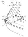
図1〜図6に示すように、4つの吊下支持部(54)は、空気吸込口(51a)の内周に設けられ、グリル(52)を吊り下げるとともに板部材(53)を支持する。具体的には、各吊下支持部(54)は、第1延出部(54a)と第2延出部(54b)とを有している。なお、図5は、斜め上方から見た吊下支持部(54)を拡大して示した部分斜視図である。図6は、吊下支持部(54)の第1延出部(54a)の延出方向に沿う化粧パネル(50)の縦断面のうち吊下支持部(54)の近傍を拡大して示した部分縦断面図であり、図4のVI−VI線における部分縦断面図に相当する。
<Hanging support part>
As shown in FIGS. 1 to 6, the four suspension support portions (54) are provided on the inner periphery of the air suction port (51a), suspend the grille (52) and support the plate member (53). . Specifically, each suspension support part (54) has a first extension part (54a) and a second extension part (54b). FIG. 5 is an enlarged partial perspective view of the suspension support portion (54) as viewed obliquely from above. FIG. 6 shows an enlarged view of the vicinity of the suspension support portion (54) in the longitudinal section of the decorative panel (50) along the extending direction of the first extension portion (54a) of the suspension support portion (54). FIG. 6 is a partial vertical cross-sectional view corresponding to a partial vertical cross-sectional view taken along line VI-VI in FIG. 4.
各吊下支持部(54)において、第1延出部(54a)は、空気吸込口(51a)の内周部から内周側へ向けて延出し、第2延出部(54b)は、第1延出部(54a)と一体に形成されて第1延出部(54a)の先端部から下方に延出している。なお、「空気吸込口(53)の内周部」とは、パネル本体(51)のうち空気吸込口(51a)を構成する部分(空気吸込口(51a)を囲う部分)のことである。すなわち、空気吸込口(51a)の内周部には、パネル本体(51)のうち空気吸込口(51a)の内周面に相当する部分だけでなく、パネル本体(51)のうち空気吸込口(51a)の内周面に連続する部分(例えば、空気吸込口(51a)の内周面の上端に連続する上端面の内周縁部)も含まれている。なお、この例では、第1延出部(54a)(延出部)は、空気吸込口(51a)の内周面から内周側へ向けて延出し、第2延出部(54b)(垂下部)は、第1延出部(54a)と一体に形成されて第1延出部(54a)の先端部から垂下している。 In each suspension support part (54), the first extension part (54a) extends from the inner peripheral part of the air suction port (51a) toward the inner peripheral side, and the second extension part (54b) The first extending portion (54a) is formed integrally with the first extending portion (54a) and extends downward from the tip end portion. The “inner peripheral portion of the air suction port (53)” refers to a portion of the panel body (51) that constitutes the air suction port (51a) (a portion that surrounds the air suction port (51a)). That is, not only the part corresponding to the inner peripheral surface of the air suction port (51a) in the panel body (51) but also the air suction port in the panel body (51) is provided in the inner peripheral part of the air suction port (51a). A portion (for example, an inner peripheral edge portion of the upper end surface continuing to the upper end of the inner peripheral surface of the air suction port (51a)) including the inner peripheral surface of (51a) is also included. In this example, the first extension part (54a) (extension part) extends from the inner peripheral surface of the air suction port (51a) toward the inner peripheral side, and the second extension part (54b) ( The hanging portion is formed integrally with the first extending portion (54a) and hangs down from the distal end portion of the first extending portion (54a).
また、この例では、第1延出部(54a)は、空気吸込口(51a)の内周部から内周側へ向けて延びる板状に形成され、第2延出部(54b)は、第1延出部(54a)の先端部から下方に延出する板状に形成されている。具体的には、吊下支持部(54)の第1延出部(54a)は、それぞれが上下に起立した状態で互いに間隔をおいて空気吸込口(51a)の内周面から内周側へ向けて延びる一対の板状に形成されている。吊下支持部(54)の第2延出部(54b)は、上下に延びる板状に形成され、その短手方向の両端部が吊下支持部(54)の第1延出部(54a)の一対の先端部に接続されている。 In this example, the first extension part (54a) is formed in a plate shape extending from the inner peripheral part of the air suction port (51a) toward the inner peripheral side, and the second extension part (54b) is The first extending portion (54a) is formed in a plate shape extending downward from the tip end portion. Specifically, the first extension part (54a) of the suspension support part (54) is spaced from the inner peripheral surface of the air suction port (51a) in the state where the first extension part (54a) stands up and down. It is formed in a pair of plate shape extended toward. The second extension part (54b) of the suspension support part (54) is formed in a plate shape extending vertically, and both ends in the short direction thereof are the first extension part (54a) of the suspension support part (54). ).
グリル(52)は、4つの吊下支持部(54)の第2延出部(54b)の下端に接続されて空気吸込口(51a)の下端部に配置されている。この例では、4つの吊下支持部(54)は、グリル(52)の4つの角部にそれぞれ配置されている。具体的には、空気吸込口(51a)は、平面視において矩形状に形成され、グリル(52)は、平面視において矩形状に形成されている。そして、吊下支持部(54)の第1延出部(54a)は、平面視において空気吸込口(51a)の角部からグリル(52)の角部へ向けて延出している。吊下支持部(54)の第2延出部(54b)の下端は、グリル(52)の角部に接続されている。また、この例では、グリル(52)は、その4つの角が面取りされて丸められている。そして、吊下支持部(54)の第2延出部(54b)は、平面視において角部の外縁に沿うように湾曲している。すなわち、吊下支持部(54)の第2延出部(54b)は、円弧板状(断面が円弧の板状)に形成されている。なお、この例では、吊下支持部(54)の第2延出部(54b)がグリル(52)の角部の外縁に接続されているが、吊下支持部(54)の第2延出部(54b)は、グリル(52)の角部のうち外縁よりも内側の部分に接続されていてもよい。 The grill (52) is connected to the lower ends of the second extending portions (54b) of the four suspension support portions (54) and is disposed at the lower end of the air suction port (51a). In this example, the four suspension support portions (54) are respectively disposed at the four corner portions of the grill (52). Specifically, the air suction port (51a) is formed in a rectangular shape in a plan view, and the grill (52) is formed in a rectangular shape in a plan view. And the 1st extension part (54a) of the suspension support part (54) is extended toward the corner | angular part of a grill (52) from the corner | angular part of an air suction inlet (51a) in planar view. The lower end of the second extension part (54b) of the suspension support part (54) is connected to the corner part of the grill (52). In this example, the grill (52) is rounded with its four corners chamfered. And the 2nd extension part (54b) of the suspension support part (54) is curving so that the outer edge of a corner | angular part may be met in planar view. That is, the 2nd extension part (54b) of the suspension support part (54) is formed in circular arc plate shape (plate shape whose cross section is circular arc). In this example, the second extension part (54b) of the suspension support part (54) is connected to the outer edge of the corner of the grille (52), but the second extension part of the suspension support part (54) The protruding portion (54b) may be connected to a portion inside the outer edge of the corner portion of the grill (52).
板部材(53)は、4つの吊下支持部(54)の第1延出部(54a)の下部に接続されて空気吸込口(51a)の内周に配置されている。この例では、4つの吊下支持部(54)の第1延出部(54a)の下部は、横断面が正方形である筒状(枠状)に形成された板部材(53)の4つの角部にそれぞれ接続されている。 The plate member (53) is connected to the lower part of the first extension part (54a) of the four suspension support parts (54) and is arranged on the inner periphery of the air suction port (51a). In this example, the lower part of the first extension portion (54a) of the four suspension support portions (54) is formed by four plate members (53) formed in a cylindrical shape (frame shape) having a square cross section. Connected to each corner.
また、吊下支持部(54)の第1延出部(54a)は、その下部が板部材(53)の外周面に対応する形状に形成され、その下部に板部材(53)の外周面が接続されている。この例では、吊下支持部(54)の第1延出部(54a)は、その下部がグリル(52)の外周縁に対して凹となる円弧状に形成され、その下部に板部材(53)の外周面が嵌合した状態で接続されている。 Further, the lower portion of the first extending portion (54a) of the suspension support portion (54) is formed in a shape corresponding to the outer peripheral surface of the plate member (53), and the outer peripheral surface of the plate member (53) is formed therebelow. Is connected. In this example, the first extension part (54a) of the suspension support part (54) is formed in an arc shape whose lower part is concave with respect to the outer peripheral edge of the grill (52), and a plate member ( 53) is connected with the outer peripheral surface fitted.
なお、この例では、パネル本体(51)の一部(具体的には、空気吸込口(51a)の近傍の部分)とグリル(52)と板部材(53)と4つの吊下支持部(54)とが一体に形成されている。 In this example, a part of the panel body (51) (specifically, a part near the air suction port (51a)), a grille (52), a plate member (53), and four suspension support parts ( And 54) are integrally formed.
〈フィルタ〉
図1〜図4に示すように、フィルタ(55)は、パネル本体(51)の空気吸込口(51a)の上側に設けられ、空気吸込口(51a)を通過した空気の中の塵埃を補足するように構成されている。フィルタ(55)は、平面視において正方形型の格子枠状に形成され、パネル本体(51)の中央部の上側に取り付けられて空気吸込口(51a)を覆っている。
<filter>
As shown in FIGS. 1 to 4, the filter (55) is provided above the air suction port (51a) of the panel body (51), and supplements dust in the air that has passed through the air suction port (51a). Is configured to do. The filter (55) is formed in a square lattice frame shape in plan view, and is attached to the upper side of the central portion of the panel body (51) to cover the air suction port (51a).
この例では、フィルタ(55)は、その平面視における面積が空気吸込口(51a)の上端の開口面積と同等となるように形成されている。なお、フィルタ(55)は、その平面視における面積が空気吸込口(51a)の上端の開口面積よりも広くなるように形成されていてもよい。 In this example, the filter (55) is formed so that the area in plan view is equal to the opening area at the upper end of the air suction port (51a). The filter (55) may be formed such that the area in plan view is larger than the opening area at the upper end of the air suction port (51a).
〈風向調節羽根〉
図1〜図4に示すように、4つの風向調節羽根(56)は、パネル本体(51)の4つの空気吹出口(51b)の下端部にそれぞれ設けられ、空気吹出口(51b)を流れる空気の流れの向きを調節するように構成されている。風向調節羽根(56)は、空気吹出口(51b)の長手方向に沿って延びる板状に形成され、その長手方向の両端部に揺動軸が設けられている。そして、風向調節羽根(56)は、揺動軸を軸心として揺動可能となるように、パネル本体(51)に支持されている。
<Wind adjustment blade>
As shown in FIGS. 1 to 4, the four wind direction adjusting blades (56) are respectively provided at the lower ends of the four air outlets (51 b) of the panel body (51) and flow through the air outlet (51 b). It is configured to adjust the direction of air flow. The wind direction adjusting blade (56) is formed in a plate shape extending along the longitudinal direction of the air outlet (51b), and swing shafts are provided at both ends in the longitudinal direction. The wind direction adjusting blade (56) is supported by the panel body (51) so as to be swingable about the swing shaft.
〔化粧パネルの要部の詳細〕
次に、図7を参照して、化粧パネル(50)の要部について詳しく説明する。なお、図7の中央部は、化粧パネル(50)の縦断面を示し、図7の上部は、上方から見た化粧パネル(50)の要部(空気吸込口(51a)の近傍)を示し、図7の下部は、下方から見た化粧パネル(50)の要部を示している。また、図7の中央部では、吊下支持部(54)とフィルタ(55)と風向調節羽根(56)の図示を省略している。
[Details of essential parts of makeup panel]
Next, the main part of the decorative panel (50) will be described in detail with reference to FIG. 7 shows the longitudinal section of the decorative panel (50), and the upper part of FIG. 7 shows the main part of the decorative panel (50) viewed from above (near the air inlet (51a)). The lower part of FIG. 7 shows the main part of the decorative panel (50) viewed from below. Moreover, in the center part of FIG. 7, illustration of a suspension support part (54), a filter (55), and a wind direction adjustment blade (56) is abbreviate | omitted.
〈吸込開口の開口面積〉
図7の下部に示すように、第1吸込開口(61)の開口面積は、第2吸込開口(62)の開口面積よりも広くなっている。なお、図7では、第1吸込開口(61)には、線間隔の狭い右上がりのハッチングが付され、第2吸込開口(62)には、線間隔の狭い左上がりのハッチングが付されている。
<Opening area of suction opening>
As shown in the lower part of FIG. 7, the opening area of the first suction opening (61) is larger than the opening area of the second suction opening (62). In FIG. 7, the first suction opening (61) is provided with a right-up hatching with a narrow line interval, and the second suction opening (62) is provided with a left-up hatching with a narrow line interval. Yes.
〈開口部の開口面積〉
図7の上部に示すように、第1開口部(63)の開口面積は、第2開口部(64)の開口面積よりも広くなっている。なお、第1開口部(63)は、板部材(53)の上縁に囲まれた領域であり、第2開口部(64)は、平面視において板部材(53)の上縁と空気吸込口(51a)の内周面との間に挟まれた領域である。また、図7では、第1開口部(63)には、線間隔の広い右上がりのハッチングが付され、第2開口部(64)には、線間隔の広い左上がりのハッチングが付されている。
<Opening area of opening>
As shown in the upper part of FIG. 7, the opening area of the first opening (63) is wider than the opening area of the second opening (64). The first opening (63) is a region surrounded by the upper edge of the plate member (53), and the second opening (64) is air-suctioned with the upper edge of the plate member (53) in plan view. It is a region sandwiched between the inner peripheral surface of the mouth (51a). Further, in FIG. 7, the first opening (63) is provided with a right-upward hatching with a wide line interval, and the second opening (64) is provided with a left-upward hatching with a wide line interval. Yes.
〈開口面積の割合〉
また、第2吸込開口(62)に対する第1吸込開口(61)の開口面積の割合は、第2開口部(64)に対する第1開口部(63)の開口面積の割合よりも大きくなっている。なお、第2吸込開口(62)に対する第1吸込開口(61)の開口面積の割合は、第2開口部(64)に対する第1開口部(63)の開口面積の割合と同等となっていてもよい。
<Ratio of opening area>
The ratio of the opening area of the first suction opening (61) to the second suction opening (62) is larger than the ratio of the opening area of the first opening (63) to the second opening (64). . The ratio of the opening area of the first suction opening (61) to the second suction opening (62) is equivalent to the ratio of the opening area of the first opening (63) to the second opening (64). Also good.
〈板部材の下縁の位置〉
図7の中央部に示すように、板部材(53)の下縁の高さは、空気吸込口(51a)の下端の高さと同一となっている。なお、板部材(53)の下縁の高さは、空気吸込口(51a)の下端の高さよりも高くなっていてもよい。また、この例では、図7の下部に示すように、板部材(53)の下縁は、平面視において吸込開口(60)の内周縁と外周縁との間の中心線(CL)よりも外周側に位置している。また、この例では、図7の中央部に示すように、板部材(53)の下縁の高さは、グリル(52)の下面の高さと同一となっている。なお、板部材(53)の下縁の高さは、グリル(52)の下面の高さよりも高くなっていてもよい。
<The position of the lower edge of the plate member>
As shown in the center of FIG. 7, the height of the lower edge of the plate member (53) is the same as the height of the lower end of the air suction port (51a). In addition, the height of the lower edge of the plate member (53) may be higher than the height of the lower end of the air suction port (51a). Moreover, in this example, as shown in the lower part of FIG. 7, the lower edge of the plate member (53) is more than the center line (CL) between the inner peripheral edge and the outer peripheral edge of the suction opening (60) in plan view. Located on the outer periphery. Moreover, in this example, as shown in the center part of FIG. 7, the height of the lower edge of the plate member (53) is the same as the height of the lower surface of the grill (52). In addition, the height of the lower edge of the plate member (53) may be higher than the height of the lower surface of the grill (52).
なお、「板部材(53)の下縁の高さが空気吸込口(51a)の下端の高さ(または、グリル(52)の下面の高さ)と同一となっている」という状態には、板部材(53)の下縁の高さが空気吸込口(51a)の下端の高さ(または、グリル(52)の下面の高さ)と完全に同一となっている状態(例えば、高低差がゼロとなっている状態)だけでなく、板部材(53)の下縁の高さが空気吸込口(51a)の下端の高さ(または、グリル(52)の下面の高さ)と実質的に同一となっている状態(例えば、高低差が約5mm以内となっている状態)も含まれている。 It should be noted that the state that the height of the lower edge of the plate member (53) is the same as the height of the lower end of the air inlet (51a) (or the height of the lower surface of the grill (52)) The state in which the height of the lower edge of the plate member (53) is completely the same as the height of the lower end of the air inlet (51a) (or the height of the lower surface of the grill (52)) The height of the lower edge of the plate member (53) is the height of the lower end of the air inlet (51a) (or the height of the lower surface of the grill (52)) The state (for example, the state where the height difference is about 5 mm or less) that is substantially the same is also included.
〈板部材の上縁の位置〉
図7の上部および中央部に示すように、板部材(53)の上縁は、平面視においてグリル(52)の外周縁と重なっている。なお、板部材(53)の上縁は、平面視においてグリル(52)の外周縁よりも内周側に位置していてもよい。
<Position of upper edge of plate member>
As shown in the upper part and the center part of FIG. 7, the upper edge of the plate member (53) overlaps with the outer peripheral edge of the grill (52) in plan view. The upper edge of the plate member (53) may be located on the inner peripheral side of the outer peripheral edge of the grill (52) in plan view.
〔室内ユニットの外観〕
次に、下方から見た室内ユニット(10)の外観について説明する。図2に示すように、板部材(53)は、その上縁が下縁よりも内周側に位置するように、空気吸込口(51a)の内周に配置されている。そのため、図3に示すように、天井(CE)に設けられた室内ユニット(10)を下方から見た場合、吸込開口(60)から室内ユニット(10)の内部部品(この例では、フィルタ(55))が見えにくくなっている。
[Appearance of indoor unit]
Next, the appearance of the indoor unit (10) viewed from below will be described. As shown in FIG. 2, the plate member (53) is disposed on the inner periphery of the air suction port (51a) so that the upper edge thereof is located on the inner periphery side of the lower edge. Therefore, as shown in FIG. 3, when the indoor unit (10) provided on the ceiling (CE) is viewed from below, the internal parts of the indoor unit (10) from the suction opening (60) (in this example, the filter ( 55)) is difficult to see.
この例では、板部材(53)は、その上縁が平面視においてグリル(52)の外周縁と重なり、その下縁が平面視において吸込開口(60)の内周縁と外周縁との間に位置するように配置されている。そのため、室内ユニット(10)を下方から見た場合、吸込開口(60)のうち平面視において板部材(53)の下縁よりも外周側に位置する領域(すなわち、第2吸込開口(62))では、フィルタ(55)の一部が見えているが、吸込開口(60)のうち平面視において板部材(53)の下縁よりも内周側に位置する領域(すなわち、第1吸込開口(61))では、フィルタ(55)の残部が板部材(53)に隠れて見えなくなっている。 In this example, the upper edge of the plate member (53) overlaps with the outer peripheral edge of the grill (52) in a plan view, and the lower edge thereof is between the inner peripheral edge and the outer peripheral edge of the suction opening (60) in a plan view. It is arranged to be located. Therefore, when the indoor unit (10) is viewed from below, a region of the suction opening (60) located on the outer peripheral side of the lower edge of the plate member (53) in plan view (that is, the second suction opening (62)). ), A part of the filter (55) is visible, but the region of the suction opening (60) located on the inner peripheral side of the lower edge of the plate member (53) in plan view (that is, the first suction opening) (61)), the remaining part of the filter (55) is hidden behind the plate member (53) and cannot be seen.
〔室内ユニットにおける空気の流れ〕
次に、図8を参照して、室内ユニット(10)における空気の流れについて説明する。なお、図8では、吊下支持部(54)の図示を省略している。
[Air flow in indoor units]
Next, the flow of air in the indoor unit (10) will be described with reference to FIG. In addition, illustration of the suspension support part (54) is abbreviate | omitted in FIG.
室内ファン(31)が駆動すると、吸込開口(60)から空気吸込口(51a)へ室内空気が吸い込まれる。空気吸込口(51a)では、吸込開口(60)から吸い込まれた室内空気は、板部材(53)の下縁において板部材(53)の内周側と外周側とに分流され、板部材(53)の内周側を流れる空気と、板部材(53)の外周側を流れる空気とに分かれる。すなわち、空気吸込口(51a)の内部には、吸込開口(60)から板部材(53)の内周側を通過して空気吸込口(51a)の上端へ向けて空気が流れる第1通風経路(R1)と、吸込開口(60)から板部材(53)の外周側を通過して空気吸込口(51a)の上端へ向けて空気が流れる第2通風経路(R2)とが構成されている。 When the indoor fan (31) is driven, indoor air is sucked from the suction opening (60) into the air suction port (51a). In the air suction port (51a), the indoor air sucked from the suction opening (60) is divided into the inner peripheral side and the outer peripheral side of the plate member (53) at the lower edge of the plate member (53), and the plate member ( 53) and air flowing on the inner peripheral side of the plate member (53) and air flowing on the outer peripheral side of the plate member (53). That is, in the air suction port (51a), a first ventilation path through which air flows from the suction opening (60) through the inner peripheral side of the plate member (53) toward the upper end of the air suction port (51a). (R1) and a second ventilation path (R2) through which air flows from the suction opening (60) through the outer peripheral side of the plate member (53) toward the upper end of the air suction port (51a) are configured. .
第1通風経路(R1)では、板部材(53)の内周側に流れ込んだ空気は、板部材(53)の内周面に沿って空気吸込口(51a)の中央へ向けて案内されつつ、空気吸込口(51a)の上端へ向けて流れていく。第1通風経路(R1)を通過した空気は、フィルタ(55)の中央部を通過した後に、ベルマウス(34)を通過して室内ファン(31)に吸い込まれる。 In the first ventilation path (R1), the air flowing into the inner peripheral side of the plate member (53) is guided toward the center of the air inlet (51a) along the inner peripheral surface of the plate member (53). The air flows toward the upper end of the air inlet (51a). The air that has passed through the first ventilation path (R1) passes through the central portion of the filter (55), passes through the bell mouth (34), and is sucked into the indoor fan (31).
一方、第2通風経路(R2)では、板部材(53)の外周側に流れ込んだ空気は、板部材(53)によって流れの向きを大幅に変更されることなく、板部材(53)の外周面と空気吸込口(51a)の内周面との間を通過して空気吸込口(51a)の上端へ向けて流れていく。第2通風経路(R2)を通過した空気は、フィルタ(55)の周縁部(中央部の周囲の部分)を通過した後に、ベルマウス(34)を通過して室内ファン(31)に吸い込まれる。 On the other hand, in the second ventilation path (R2), the air flowing into the outer peripheral side of the plate member (53) does not significantly change the flow direction by the plate member (53), and the outer periphery of the plate member (53). It passes between the surface and the inner peripheral surface of the air suction port (51a) and flows toward the upper end of the air suction port (51a). The air that has passed through the second ventilation path (R2) passes through the peripheral edge of the filter (55) (portion around the center), and then passes through the bell mouth (34) and is sucked into the indoor fan (31). .
室内ファン(31)に吸い込まれた空気は、室内ファン(31)の側方から径方向外方へ吹き出される。室内ファン(31)から吹き出された空気は、室内熱交換器(32)を通過する際に室内熱交換器(32)を流れる冷媒と熱交換する。室内熱交換器(32)を通過した空気は、4つの空気導出口(33b)に分流されて4つの空気導出口(33b)を下方へ向けて流れる。4つの空気導出口(33b)を通過した空気は、それぞれ、4つの吸込連通口(40a)と4つの空気吹出口(51b)とを順に通過して室内に吹き出される。 The air sucked into the indoor fan (31) is blown out radially outward from the side of the indoor fan (31). The air blown out from the indoor fan (31) exchanges heat with the refrigerant flowing through the indoor heat exchanger (32) when passing through the indoor heat exchanger (32). The air that has passed through the indoor heat exchanger (32) is divided into four air outlets (33b) and flows downward through the four air outlets (33b). The air that has passed through the four air outlets (33b) passes through the four suction communication ports (40a) and the four air outlets (51b) in order, and is blown out into the room.
〔実施形態1による効果〕
以上のように、吊下支持部(54)を用いてグリル(52)を支持することにより、ワイヤによってグリル(52)が吊り下げられている場合よりも、グリル(52)を強固に支持することができる。また、平面視においてグリル(52)の外周縁と空気吸込口(51a)の開口縁との間に吸込開口(60)が形成されるように、グリル(52)が空気吸込口(51a)の中央部を覆うことにより、吸込開口(60)の開口面積を確保することができる。このように、吸込開口(60)の開口面積を確保しつつ、グリル(52)を強固に支持することができるので、吸込開口(60)における通風抵抗の増加を抑制しつつ、グリル(52)の支持を安定させることができる。
[Effects of Embodiment 1]
As described above, by supporting the grill (52) using the suspension support portion (54), the grill (52) is supported more firmly than when the grill (52) is suspended by the wire. be able to. In addition, the grill (52) is connected to the air suction port (51a) so that the suction opening (60) is formed between the outer peripheral edge of the grill (52) and the opening edge of the air suction port (51a) in plan view. By covering the central part, the opening area of the suction opening (60) can be secured. As described above, the grill (52) can be firmly supported while securing the opening area of the suction opening (60), and therefore, the grill (52) is suppressed while suppressing an increase in ventilation resistance in the suction opening (60). Can be stabilized.
また、吊下支持部(54)の第1延出部(54a)を上下に起立した状態の板状に形成することにより、吊下支持部(54)の配置に起因する通風抵抗の増加を抑制することができる。これにより、空気吸込口(51a)を通過する空気の流れを円滑にすることができる。 In addition, by forming the first extension part (54a) of the suspension support part (54) in a plate-like state standing up and down, an increase in ventilation resistance due to the arrangement of the suspension support part (54) is achieved. Can be suppressed. Thereby, the flow of the air which passes an air suction inlet (51a) can be made smooth.
また、吊下支持部(54)の第1延出部(54a)を一対の板状に形成することにより、第1延出部(54a)が一つの板状に形成されている場合よりも、吊下支持部(54)の第1延出部(54a)とパネル本体(51)との間の接続強度および吊下支持部(54)の第1延出部(54a)と第2延出部(54b)との間の接続強度を向上させることができる。また、吊下支持部(54)の第2延出部(54b)を板状に形成することにより、吊下支持部(54)の第2延出部(54b)が棒状に形成されている場合よりも、吊下支持部(54)の第2延出部(54b)とグリル(52)との接続面積を広くすることができる。これにより、吊下支持部(54)とグリル(52)との間の接続強度を向上させることができる。このように、吊下支持部(54)の第1延出部(54a)とパネル本体(51)との間の接続強度と、吊下支持部(54)の第1延出部(54a)と第2延出部(54b)との間の接続強度と、吊下支持部(54)とグリル(52)との間の接続強度とを向上させることができるので、グリル(52)の支持の安定性を向上させることができる。 Further, by forming the first extension part (54a) of the suspension support part (54) in a pair of plate shapes, the first extension part (54a) is formed in a single plate shape. The connection strength between the first extension part (54a) of the suspension support part (54) and the panel body (51) and the first extension part (54a) and the second extension of the suspension support part (54) The connection strength between the projecting portion (54b) can be improved. Moreover, the 2nd extension part (54b) of the suspension support part (54) is formed in rod shape by forming the 2nd extension part (54b) of the suspension support part (54) in plate shape. The connection area between the second extension part (54b) of the suspension support part (54) and the grill (52) can be made wider than the case. Thereby, the connection strength between the suspension support part (54) and the grille (52) can be improved. Thus, the connection strength between the first extension part (54a) of the suspension support part (54) and the panel body (51), and the first extension part (54a) of the suspension support part (54). Since the connection strength between the second extension portion (54b) and the connection strength between the suspension support portion (54) and the grill (52) can be improved, the support of the grill (52) can be improved. Stability can be improved.
また、吊下支持部(54)をパネル本体(51)およびグリル(52)と一体に形成することにより、吊下支持部(54)とパネル本体(51)との間の接続強度および吊下支持部(54)とグリル(52)との間の接続強度を向上させることができる。これにより、グリル(52)の支持の安定性を向上させることができる。 Further, by forming the suspension support part (54) integrally with the panel body (51) and the grill (52), the connection strength between the suspension support part (54) and the panel body (51) and suspension The connection strength between the support portion (54) and the grill (52) can be improved. Thereby, the stability of the support of the grill (52) can be improved.
なお、吊下支持部(54)は、パネル本体(51)と一体に形成される一方でグリル(52)と別体に形成されていてもよいし、グリル(52)と一体に形成される一方でパネル本体(51)と別体に形成されていてもよい。吊下支持部(54)をパネル本体(51)と一体に形成することにより、吊下支持部(54)とパネル本体(51)との間の接続強度を向上させることができ、吊下支持部(54)をグリル(52)と一体に形成することにより、吊下支持部(54)とグリル(52)との間の接続強度を向上させることができる。すなわち、吊下支持部(54)をパネル本体(51)およびグリル(52)のうち少なくとも一方と一体に形成することにより、吊下支持部(54)とパネル本体(51)との間の接続強度および吊下支持部(54)とグリル(52)との間の接続強度のうち少なくとも一方を向上させることができ、グリル(52)の支持の安定性を向上させることができる。 The suspension support portion (54) may be formed separately from the grill (52) while being formed integrally with the panel body (51), or may be formed integrally with the grill (52). On the other hand, it may be formed separately from the panel body (51). By forming the suspension support part (54) integrally with the panel body (51), the connection strength between the suspension support part (54) and the panel body (51) can be improved. By forming the portion (54) integrally with the grill (52), the connection strength between the suspension support portion (54) and the grill (52) can be improved. That is, the suspension support portion (54) is integrally formed with at least one of the panel body (51) and the grill (52), thereby connecting the suspension support portion (54) and the panel body (51). At least one of the strength and the connection strength between the suspension support portion (54) and the grill (52) can be improved, and the support stability of the grill (52) can be improved.
また、吊下支持部(54)をグリル(52)の角部に配置することにより、吊下支持部(54)をグリル(52)の辺部に配置する場合よりも、グリル(52)を強固に支持することができる。これにより、グリル(52)の支持の安定性を向上させることができる。 In addition, by disposing the suspension support portion (54) at the corner of the grill (52), the grill (52) can be made more than when the suspension support portion (54) is disposed at the side of the grill (52). It can be firmly supported. Thereby, the stability of the support of the grill (52) can be improved.
また、板部材(53)の上縁が下縁よりも内周側に位置し、板部材(53)の上縁が空気吸込口(51a)の下端よりも上方に位置し、板部材(53)の下縁が平面視においてグリル(52)の外周を囲うように板部材(53)を設けることにより、吸込開口(60)の開口面積を確保しつつ、吸込開口(60)から室内ユニット(10)の内部部品(この例では、フィルタ(55))を見えにくくすることができる。これにより、吸込開口(60)における通風抵抗の増加を抑制しつつ化粧パネル(50)の意匠性を向上させることができる。 Further, the upper edge of the plate member (53) is located on the inner peripheral side with respect to the lower edge, the upper edge of the plate member (53) is located above the lower end of the air suction port (51a), and the plate member (53 ) By providing the plate member (53) so that the lower edge surrounds the outer periphery of the grill (52) in plan view, while ensuring the opening area of the suction opening (60), the indoor unit ( The internal parts of 10) (in this example, the filter (55)) can be made difficult to see. Thereby, the design property of a decorative panel (50) can be improved, suppressing the increase in ventilation resistance in a suction opening (60).
また、吊下支持部(54)の第1延出部(54a)の下部を板部材(53)の外周面に対応する形状に形成して板部材(53)の外周面を接続することにより、吊下支持部(54)と板部材(53)との接続面積を広くすることができる。これにより、吊下支持部(54)と板部材(53)との間の接続強度を向上させることができるので、吊下支持部(54)による板部材(53)の支持を強化することができる。 Moreover, by forming the lower part of the 1st extension part (54a) of a suspension support part (54) in the shape corresponding to the outer peripheral surface of a plate member (53), and connecting the outer peripheral surface of a plate member (53) The connection area between the suspension support part (54) and the plate member (53) can be increased. Thereby, since the connection strength between the suspension support portion (54) and the plate member (53) can be improved, the support of the plate member (53) by the suspension support portion (54) can be strengthened. it can.
また、板部材(53)の上縁が下縁よりも内周側に位置するように板部材(53)を設けることにより、板部材(53)の内周側に流れ込んだ空気を空気吸込口(51a)の中央へ向けて案内することができる。これにより、空気吸込口(51a)の中央部(平面視における中央部)を通過する空気の流れを促進させることができる。 Further, by providing the plate member (53) so that the upper edge of the plate member (53) is located on the inner peripheral side with respect to the lower edge, air flowing into the inner peripheral side of the plate member (53) Guide to the center of (51a). Thereby, the flow of the air which passes the center part (center part in planar view) of an air suction inlet (51a) can be promoted.
なお、一般的に、室内ファン(31)の吸込口は、平面視において室内ユニット本体(20)の中央部(この例では、ドレンパン(33)に形成された空気導入口(33a)の中央部)に配置されることが多い。したがって、空気吸込口(51a)の中央部を通過する空気の流れを促進させることにより、室内ユニット本体(20)において室内ファン(31)による空気の吸い込みを促進させることができる。これにより、室内ユニット本体(20)における空気の吸込効率を向上させることができる。 In general, the suction port of the indoor fan (31) is a central portion of the indoor unit body (20) in a plan view (in this example, the central portion of the air introduction port (33a) formed in the drain pan (33)). ) In many cases. Therefore, by promoting the flow of air passing through the central portion of the air suction port (51a), it is possible to promote air suction by the indoor fan (31) in the indoor unit body (20). Thereby, the air suction efficiency in the indoor unit body (20) can be improved.
また、グリル(52)の外周縁に対して凹となるように、板部材(53)を曲げることにより、板部材(53)がグリル(52)の外周縁に対して凸となるように曲がっている場合よりも、板部材(53)とグリル(52)との間隔を広めに確保することができる。これにより、板部材(53)の内周側における通風抵抗を低減することができ、板部材(53)の内周側を通過する空気の流れを円滑にすることができる。したがって、空気吸込口(51a)の中央部を通過する空気の流れを促進させることができる。 Further, by bending the plate member (53) so as to be concave with respect to the outer peripheral edge of the grill (52), the plate member (53) is bent so as to be convex with respect to the outer peripheral edge of the grill (52). Compared to the case, the gap between the plate member (53) and the grille (52) can be secured wider. Thereby, the ventilation resistance in the inner peripheral side of a board member (53) can be reduced, and the flow of the air which passes the inner peripheral side of a board member (53) can be made smooth. Therefore, the flow of air passing through the central portion of the air suction port (51a) can be promoted.
また、板部材(53)の下縁が平面視において吸込開口(60)を第1吸込開口(61)と第2吸込開口(62)とに区画するように板部材(53)を設けることにより、空気吸込口(51a)の内部に、板部材(53)の内周側を通過する第1通風経路(R1)に加えて、板部材(53)の外周側を通過する第2通風経路(R2)を構成することができる。なお、第2通風経路(R2)では、板部材(53)の外周側に流れ込んだ空気は、板部材(53)によって流れの向きを大幅に変更されることなく、空気吸込口(51a)の上端へ向けて流れていく。すなわち、第2通風経路(R2)における通風抵抗は、第1通風経路(R1)における通風抵抗よりも低くなっている。したがって、空気吸込口(51a)の内部に第1通風経路(R1)に加えて第2通風経路(R2)を構成することにより、吸込開口(60)から吸い込まれた空気が板部材(53)の内周側のみを通過する場合(すなわち、第1通風経路(R1)のみが形成されている場合)よりも、空気吸込口(51a)における通風抵抗を低減することができ、空気吸込口(51a)を通過する空気の流れを円滑にすることができる。 Further, by providing the plate member (53) so that the lower edge of the plate member (53) divides the suction opening (60) into the first suction opening (61) and the second suction opening (62) in plan view. In addition to the first ventilation path (R1) that passes through the inner peripheral side of the plate member (53), the second ventilation path that passes through the outer peripheral side of the plate member (53) inside the air inlet (51a) ( R2) can be configured. In the second ventilation path (R2), the air flowing into the outer peripheral side of the plate member (53) is not significantly changed in the flow direction by the plate member (53), and the air inlet (51a) It flows toward the top. That is, the ventilation resistance in the second ventilation path (R2) is lower than the ventilation resistance in the first ventilation path (R1). Therefore, by forming the second ventilation path (R2) in addition to the first ventilation path (R1) inside the air suction port (51a), the air sucked from the suction opening (60) is plate member (53). Ventilation resistance at the air inlet (51a) can be reduced compared to the case where only the inner peripheral side of the air is passed (that is, when only the first ventilation path (R1) is formed), and the air inlet ( The flow of air passing through 51a) can be smoothed.
また、空気吸込口(51a)における通風抵抗を低減することにより、室内ユニット本体(20)において空気を吸い込むために要する仕事量(具体的には、室内ファン(31)の回転数)を低減することができる。これにより、室内ユニット(10)における騒音(具体的には、室内ファン(31)の運転音)を低減することができる。 Further, by reducing the ventilation resistance at the air inlet (51a), the work required to suck air in the indoor unit body (20) (specifically, the rotational speed of the indoor fan (31)) is reduced. be able to. Thereby, the noise in the indoor unit (10) (specifically, the operating sound of the indoor fan (31)) can be reduced.
また、板部材(53)の下縁が平面視において吸込開口(60)を第1吸込開口(61)と第2吸込開口(62)とに区画するように板部材(53)を設けて空気吸込口(51a)の内部に第1通風経路(R1)と第2通風経路(R2)を構成することにより、第1通風経路(R1)を通過した空気をフィルタ(55)の中央部に供給し、第2通風経路(R2)を通過した空気をフィルタ(55)の周縁部(例えば、室内ユニット(10)を下方から見た場合に板部材(53)に隠れている部分)に供給することができる。これにより、フィルタ(55)の中央部だけでなくフィルタ(55)の周縁部も有効に利用することができる。 The plate member (53) is provided with a plate member (53) so that the lower edge of the plate member (53) divides the suction opening (60) into a first suction opening (61) and a second suction opening (62) in plan view. Supply the air that has passed through the first ventilation path (R1) to the center of the filter (55) by configuring the first ventilation path (R1) and the second ventilation path (R2) inside the suction port (51a) Then, the air that has passed through the second ventilation path (R2) is supplied to the peripheral portion of the filter (55) (for example, the portion hidden by the plate member (53) when the indoor unit (10) is viewed from below). be able to. Thereby, not only the center part of the filter (55) but also the peripheral part of the filter (55) can be used effectively.
また、第1吸込開口(61)の開口面積を第2吸込開口(62)の開口面積よりも広くすることにより、第1通風経路(R1)の入口における通風抵抗を、第2通風経路(R2)の入口における通風抵抗よりも低くすることができる。これにより、第1通風経路(R1)への空気の流入を促進させることができるので、空気吸込口(51a)の中央部を通過する空気の流れを促進させることができる。 Further, by making the opening area of the first suction opening (61) larger than the opening area of the second suction opening (62), the ventilation resistance at the inlet of the first ventilation path (R1) is reduced to the second ventilation path (R2). ) Can be lower than the draft resistance at the entrance. Thereby, since inflow of the air to the 1st ventilation path (R1) can be accelerated | stimulated, the flow of the air which passes the center part of an air suction inlet (51a) can be promoted.
また、第1開口部(63)の開口面積を第2開口部(64)の開口面積よりも広くすることにより、第1通風経路(R1)の出口における通風抵抗を、第2通風経路(R2)の出口における通風抵抗よりも低くすることができる。これにより、第1通風経路(R1)からの空気の流出を促進させることができるので、空気吸込口(51a)の中央部を通過する空気の流れを促進させることができる。 Further, by making the opening area of the first opening (63) wider than the opening area of the second opening (64), the ventilation resistance at the outlet of the first ventilation path (R1) is reduced to the second ventilation path (R2). ) Can be made lower than the draft resistance at the outlet. Thereby, since the outflow of the air from the 1st ventilation path (R1) can be accelerated | stimulated, the flow of the air which passes the center part of an air suction inlet (51a) can be accelerated | stimulated.
また、第2吸込開口(62)に対する第1吸込開口(61)の開口面積の割合を、第2開口部(64)に対する第1開口部(63)の開口面積の割合よりも大きくするか同等とすることにより、そうでない場合(すなわち、第2吸込開口(62)に対する第1吸込開口(61)の開口面積の割合が第2開口部(64)に対する第1開口部(63)の開口面積の割合よりも小さくなっている場合)よりも、第1通風経路(R1)を通過する空気の流れを円滑にすることができる。これにより、空気吸込口(51a)の中央部を通過する空気の流れを促進させることができる。 Further, the ratio of the opening area of the first suction opening (61) to the second suction opening (62) is greater than or equal to the ratio of the opening area of the first opening (63) to the second opening (64). If this is not the case (that is, the ratio of the opening area of the first suction opening (61) to the second suction opening (62) is the opening area of the first opening (63) relative to the second opening (64)). The flow of the air passing through the first ventilation path (R1) can be made smoother than when the ratio is smaller than the above-mentioned ratio. Thereby, the flow of the air which passes the center part of an air suction inlet (51a) can be promoted.
また、板部材(53)の下縁の高さを空気吸込口(51a)の下端の高さと同一または空気吸込口(51a)の下端の高さよりも高くすることにより、板部材(53)の下縁が空気吸込口(51a)から下方に突き出している場合よりも、板部材(53)を目立ちにくくすることができる。これにより、化粧パネル(50)の意匠性を向上させることができる。 Further, the height of the lower edge of the plate member (53) is made equal to the height of the lower end of the air suction port (51a) or higher than the height of the lower end of the air suction port (51a). The plate member (53) can be made less noticeable than when the lower edge protrudes downward from the air inlet (51a). Thereby, the designability of a decorative panel (50) can be improved.
また、板部材(53)の下縁が平面視において吸込開口(60)の内周縁と外周縁との間の中心線(CL)よりも外周側に位置するように板部材(53)を設けることにより、板部材(53)の下縁が平面視において中心線(CL)よりも内周側に位置している場合よりも、吸込開口(60)の外周縁と板部材(53)の下縁との間の隙間を狭くすることができる。これにより、吸込開口(60)から室内ユニット(10)の内部部品を見えにくくすることができるので、化粧パネル(50)の意匠性を向上させることができる。 Further, the plate member (53) is provided so that the lower edge of the plate member (53) is located on the outer peripheral side with respect to the center line (CL) between the inner peripheral edge and the outer peripheral edge of the suction opening (60) in plan view. Therefore, the lower edge of the suction opening (60) and the lower part of the plate member (53) are lower than when the lower edge of the plate member (53) is located on the inner peripheral side of the center line (CL) in plan view. The gap between the edges can be narrowed. Thereby, since the internal components of the indoor unit (10) can be hardly seen from the suction opening (60), the design of the decorative panel (50) can be improved.
また、板部材(53)の上縁が平面視においてグリル(52)の外周縁と重なるかグリル(52)の外周縁よりも内周側に位置するように板部材(53)を設けることにより、室内ユニット(10)を下方から平面的に見た場合に、吸込開口(60)のうち板部材(53)の下縁よりも内周側に位置する領域において室内ユニット(10)の内部部品を見えないようにすることができる。これにより、化粧パネル(50)の意匠性を向上させることができる。 Further, by providing the plate member (53) so that the upper edge of the plate member (53) overlaps with the outer peripheral edge of the grill (52) in a plan view or is located on the inner peripheral side of the outer peripheral edge of the grill (52). When the indoor unit (10) is viewed in plan view from below, the internal parts of the indoor unit (10) in the area of the suction opening (60) located on the inner peripheral side of the lower edge of the plate member (53) Can be invisible. Thereby, the designability of a decorative panel (50) can be improved.
また、グリル(52)の下面の高さが空気吸込口(51a)の下端の高さと同一となるようにグリル(52)を設けることにより、パネル本体(51)の下方にグリル(52)が突き出している場合よりも、パネル本体(51)とグリル(52)との一体感(平坦な印象)を高めることができる。これにより、化粧パネル(50)の意匠性を向上させることができる。 In addition, the grill (52) is provided below the panel body (51) by providing the grill (52) so that the lower surface of the grill (52) has the same height as the lower end of the air inlet (51a). The sense of unity (flat impression) between the panel main body (51) and the grill (52) can be enhanced as compared with the case of protruding. Thereby, the designability of a decorative panel (50) can be improved.
〔板部材の変形例〕
図9に示すように、板部材(53)の下縁から上縁へ向かうに連れて、グリル(52)の外周縁を曲率中心とする板部材(53)の曲率半径(CR)が次第に大きくなるように、板部材(53)が構成されていてもよい。なお、図9では、板部材(53)の上縁から下縁に亘って板部材(53)の曲率半径が同一である場合の板部材(53)の内周面を二点鎖線で示している。
[Modification of plate member]
As shown in FIG. 9, as the plate member (53) moves from the lower edge to the upper edge, the radius of curvature (CR) of the plate member (53) centering on the outer periphery of the grill (52) gradually increases. As such, the plate member (53) may be configured. In FIG. 9, the inner peripheral surface of the plate member (53) when the curvature radius of the plate member (53) is the same from the upper edge to the lower edge of the plate member (53) is indicated by a two-dot chain line. Yes.
以上のように構成することにより、板部材(53)の下縁から上縁へ向かうに連れて、板部材(53)とグリル(52)との間隔を次第に広くすることができる。これにより、板部材(53)の下縁から上縁へ向かうに連れて、板部材(53)の内周側における通風抵抗を次第に低くすることができ、板部材(53)の内周側を通過する空気の流れ(すなわち、第1通風経路(R1)を通過する空気の流れ)を円滑にすることができる。したがって、空気吸込口(51a)の中央部を通過する空気の流れを促進させることができる。 By configuring as described above, the distance between the plate member (53) and the grill (52) can be gradually increased from the lower edge to the upper edge of the plate member (53). Thereby, as it goes from the lower edge to the upper edge of the plate member (53), the ventilation resistance on the inner peripheral side of the plate member (53) can be gradually lowered, and the inner peripheral side of the plate member (53) is reduced. The flow of air passing therethrough (that is, the flow of air passing through the first ventilation path (R1)) can be made smooth. Therefore, the flow of air passing through the central portion of the air suction port (51a) can be promoted.
〔板部材の他の変形例〕
また、図10に示すように、板部材(53)は、グリル(52)の外周縁に対して凹となるL字状に湾曲(または屈曲)するように形成されていてもよい。または、図11に示すように、板部材(53)は、空気吸込口(51a)の外周側から内周側へ向けて直線的に上方傾斜するように形成されていてもよい。
[Other variations of plate members]
As shown in FIG. 10, the plate member (53) may be formed to be bent (or bent) into an L shape that is concave with respect to the outer peripheral edge of the grill (52). Or as shown in FIG. 11, the plate member (53) may be formed so as to incline linearly upward from the outer peripheral side of the air suction port (51a) toward the inner peripheral side.
以上のように構成した場合も、板部材(53)の内周側に流れ込んだ空気を空気吸込口(51a)の中央へ向けて案内することができ、空気吸込口(51a)の中央部を通過する空気の流れを促進させることができる。 Even when configured as described above, the air flowing into the inner peripheral side of the plate member (53) can be guided toward the center of the air suction port (51a), and the central portion of the air suction port (51a) can be guided. The flow of air passing therethrough can be promoted.
なお、板部材(53)がグリル(52)の外周縁に対して凹となるように曲がっている場合(図2,図9,図10)は、板部材(53)が空気吸込口(51a)の外周側から内周側へ向けて直線的に上方傾斜している場合(図11)よりも、板部材(53)とグリル(52)との間隔を広めに確保することができる。 When the plate member (53) is bent so as to be concave with respect to the outer peripheral edge of the grill (52) (FIGS. 2, 9, and 10), the plate member (53) is connected to the air suction port (51a). ), The gap between the plate member (53) and the grille (52) can be ensured wider than the case where it is linearly inclined upward from the outer peripheral side to the inner peripheral side (FIG. 11).
〔化粧パネルの変形例〕
図12に示すように、グリル(52)は、その下面の高さが空気吸込口(51a)の下端の高さよりも高くなるように、空気吸込口(51a)の下端部に設けられていてもよい。この例では、グリル(52)は、その下面が平坦面状に形成され、その下面がパネル本体(51)の下面と平行となっている。
[Modified example of decorative panel]
As shown in FIG. 12, the grill (52) is provided at the lower end of the air inlet (51a) so that the lower surface of the grill (52) is higher than the lower end of the air inlet (51a). Also good. In this example, the lower surface of the grill (52) is formed into a flat surface, and the lower surface is parallel to the lower surface of the panel body (51).
以上のように構成した場合も、パネル本体(51)の下方にグリル(52)が突き出している場合よりも、パネル本体(51)とグリル(52)との一体感を高めることができる。 Also when comprised as mentioned above, a sense of unity with a panel main body (51) and a grill (52) can be improved rather than the case where a grill (52) has projected below the panel main body (51).
〔吊下支持部の変形例1〕
図13に示すように、4つの吊下支持部(54)は、グリル(52)の4つの辺部(この例では、4つの辺部の中央部)にそれぞれ配置されていてもよい。この例では、空気吸込口(51a)は、平面視において矩形状に形成され、グリル(52)は、平面視において矩形状に形成されている。そして、吊下支持部(54)の第1延出部(54a)は、平面視において空気吸込口(51a)の辺部からグリル(52)の辺部へ向けて延出している。吊下支持部(54)の第2延出部(54b)の下端は、グリル(52)の辺部に接続されている。なお、吊下支持部(54)の第2延出部(54b)は、グリル(52)の辺部の外縁に接続されていてもよいし、グリル(52)の辺部のうち外縁よりも内側の部分に接続されていてもよい。また、吊下支持部(54)の第1延出部(54a)の下部は、横断面が正方形である筒状(枠状)に形成された板部材(53)の4つの辺部にそれぞれ接続されている。
[Variation 1 of the suspension support section]
As shown in FIG. 13, the four suspension support portions (54) may be disposed on four sides of the grill (52) (in this example, the center of the four sides). In this example, the air suction port (51a) is formed in a rectangular shape in plan view, and the grill (52) is formed in a rectangular shape in plan view. And the 1st extension part (54a) of the suspension support part (54) is extended toward the side part of a grille (52) from the side part of an air suction inlet (51a) in planar view. The lower end of the second extension part (54b) of the suspension support part (54) is connected to the side part of the grill (52). In addition, the 2nd extension part (54b) of a suspension support part (54) may be connected to the outer edge of the side part of a grill (52), and is more than an outer edge among the side parts of a grille (52). It may be connected to the inner part. The lower part of the first extension part (54a) of the suspension support part (54) is respectively connected to the four side parts of the plate member (53) formed in a cylindrical shape (frame shape) having a square cross section. It is connected.
なお、空気吸込口(51a)の辺部とは、平面視において矩形状に形成された空気吸込口(51a)の内周縁部のうち空気吸込口(51a)の辺に沿う部分のことであり、空気吸込口(51a)の内周縁部のうち空気吸込口(51a)の4つの角部(空気吸込口(51a)の角を含む部分)を除いた部分のことである。これと同様に、グリル(52)の辺部とは、平面視において矩形状に形成されたグリル(52)の外周縁部のうちグリル(52)の辺に沿う部分のことであり、グリル(52)の外周縁部のうちグリル(52)の4つ角部(グリル(52)の角を含む部分)を除いた部分のことである。また、板部材(53)の辺部とは、平面視において矩形枠状に形成された板部材(53)の辺に沿う部分のことであり、板部材(53)の角部(板部材(53)の角を含む部分)を除いた部分のことである。 In addition, the side part of the air suction port (51a) is a part along the side of the air suction port (51a) in the inner peripheral edge of the air suction port (51a) formed in a rectangular shape in plan view. It is a portion excluding the four corners of the air suction port (51a) (the portion including the corners of the air suction port (51a)) of the inner peripheral edge of the air suction port (51a). Similarly, the side portion of the grill (52) is a portion along the side of the grill (52) in the outer peripheral portion of the grill (52) formed in a rectangular shape in plan view. 52) is a portion excluding the four corners of the grill (52) (the portion including the corner of the grill (52)) of the outer peripheral edge of 52). Moreover, the side part of a plate member (53) is a part along the side of the plate member (53) formed in the rectangular frame shape in planar view, and the corner | angular part (plate member ( It is the part excluding the part including the corner of 53).
図13に示した化粧パネル(50)では、吸込開口(60)のうち空気吸込口(51a)の角部とグリル(52)の角部との間に挟まれた領域を通過する空気の流速は、吸込開口(60)のうち空気吸込口(51a)の辺部とグリル(52)の辺部との間に挟まれた領域を通過する空気の流速よりも速くなる傾向にある。したがって、吊下支持部(54)をグリル(52)の辺部に配置することにより、吊下支持部(54)の配置に起因する通風抵抗の増加を効果的に抑制することができる。これにより、空気吸込口(51a)を通過する空気の流れを円滑にすることができる。 In the decorative panel (50) shown in FIG. 13, the flow velocity of the air passing through the region sandwiched between the corner of the air inlet (51a) and the corner of the grill (52) in the suction opening (60). Tends to be faster than the flow velocity of air passing through a region sandwiched between the side of the air suction port (51a) and the side of the grill (52) in the suction opening (60). Therefore, by arranging the suspension support part (54) on the side part of the grill (52), it is possible to effectively suppress an increase in ventilation resistance due to the arrangement of the suspension support part (54). Thereby, the flow of the air which passes an air suction inlet (51a) can be made smooth.
〔吊下支持部の変形例2〕
図14に示すように、吊下支持部(54)は、一つの板状に形成されていてもよい。この例では、吊下支持部(54)の第1延出部(54a)は、上下に起立した状態で空気吸込口(51a)の内周面から内周側へ向けて延びる一つの板状に形成されている。吊下支持部(54)の第2延出部(54b)は、上下に延びる板状に形成され、その短手方向の一端部が吊下支持部(54)の第1延出部(54a)の先端部に接続されている。
[Modification 2 of the suspension support section]
As shown in FIG. 14, the suspension support part (54) may be formed in one plate shape. In this example, the first extension part (54a) of the suspension support part (54) is a single plate extending from the inner peripheral surface of the air suction port (51a) toward the inner peripheral side in an upright state. Is formed. The second extension portion (54b) of the suspension support portion (54) is formed in a plate shape extending vertically, and one end portion in the short direction thereof is the first extension portion (54a) of the suspension support portion (54). ) Is connected to the tip.
以上のように、吊下支持部(54)の第1延出部(54a)を上下に起立した状態の一つの板状に形成することにより、吊下支持部(54)の配置に起因する通風抵抗の増加を抑制することができる。これにより、空気吸込口(51a)を通過する空気の流れを円滑にすることができる。また、吊下支持部(54)の第2延出部(54b)を板状に形成することにより、吊下支持部(54)の第2延出部(54b)が棒状に形成されている場合よりも、吊下支持部(54)の第2延出部(54b)とグリル(52)との接続面積を広くすることができる。これにより、吊下支持部(54)とグリル(52)との間の接続強度を向上させることができるので、グリル(52)の支持の安定性を向上させることができる。 As described above, the first extending portion (54a) of the suspension support portion (54) is formed in a single plate-like shape in the up-and-down state, thereby resulting in the arrangement of the suspension support portion (54). Increase in ventilation resistance can be suppressed. Thereby, the flow of the air which passes an air suction inlet (51a) can be made smooth. Moreover, the 2nd extension part (54b) of the suspension support part (54) is formed in rod shape by forming the 2nd extension part (54b) of the suspension support part (54) in plate shape. The connection area between the second extension part (54b) of the suspension support part (54) and the grill (52) can be made wider than the case. Thereby, since the connection strength between the suspension support part (54) and the grill (52) can be improved, the support stability of the grill (52) can be improved.
〔吊下支持部の変形例3〕
図15,図16に示すように、吊下支持部(54)は、パネル本体(51)およびグリル(52)と別体に形成されていてもよい。なお、この例では、吊下支持部(54)は、パネル本体(51)および上記グリル(52)と爪嵌合によって接続されている。
[Modification 3 of the suspension support section]
As shown in FIGS. 15 and 16, the suspension support portion (54) may be formed separately from the panel body (51) and the grill (52). In this example, the suspension support portion (54) is connected to the panel body (51) and the grill (52) by claw fitting.
詳しく説明すると、この例では、吊下支持部(54)の第1延出部(54a)は、板面が上下を向く状態で空気吸込口(51a)の内周面から内周側へ向けて延びる板状に形成され、その基端部に下方に凹んだ凹部が形成されている。吊下支持部(54)の第2延出部(54b)は、板面が上下を向く状態で吊下支持部(54)の第1延出部(54a)の先端部から内周側へ向けて下方に傾斜する板状に形成され、その先端部がグリル(52)の上面と平行となるようにL字状に屈曲している。また、パネル本体(51)には、空気吸込口(51a)の内周面から内周側に延出する延出片部(51c)が設けられている。 More specifically, in this example, the first extending portion (54a) of the suspension support portion (54) is directed from the inner peripheral surface of the air suction port (51a) toward the inner peripheral side with the plate surface facing up and down. The base end portion is formed with a concave portion that is recessed downward. The second extension part (54b) of the suspension support part (54) extends from the tip end part of the first extension part (54a) of the suspension support part (54) to the inner peripheral side with the plate surface facing up and down. It is formed in a plate shape that is inclined downward, and is bent in an L shape so that its tip end portion is parallel to the upper surface of the grill (52). Further, the panel body (51) is provided with an extending piece (51c) extending from the inner peripheral surface of the air suction port (51a) to the inner peripheral side.
グリル(52)と板部材(53)と吊下支持部(54)には、それぞれ、上方へ向けて突出する第1係合爪(71)と第2係合爪(72)と第3係合爪(73)が設けられている。具体的には、第1係合爪(71)は、グリル(52)の角部に設けられ、第2係合爪(72)は、板部材(53)の角部に設けられ、第3係合爪(73)は、吊下支持部(54)の第1延出部(54a)の基端部に形成された凹部に設けられている。第3係合爪(73)は、胴部(70a)と首部(70b)と頭部(70c)とを有している。胴部(70a)は、上方へ向けて突出する柱状に形成されている。首部(70b)は、その径が胴部(70a)の径よりも小さい円柱状に形成されている。頭部(70c)は、その径が基端部において首部(70b)の径よりも大きく、その径が基端部から先端部へ向かうに連れて次第に小さくなる円錐台形状に形成されている。また、第3係合爪(73)には、その突出方向に沿うスリットが形成されている。これにより、第3係合爪(73)は、その径が弾性変形により縮小可能に構成されている。なお、第1係合爪(71)および第2係合爪(72)も、第3係合爪(73)と同様の構成を有している。 The grille (52), the plate member (53), and the suspension support part (54) are respectively provided with a first engagement claw (71), a second engagement claw (72), and a third engagement that protrude upward. A claw (73) is provided. Specifically, the first engagement claw (71) is provided at the corner of the grill (52), the second engagement claw (72) is provided at the corner of the plate member (53), and the third The engagement claw (73) is provided in a recess formed in the base end portion of the first extension portion (54a) of the suspension support portion (54). The third engaging claw (73) has a trunk portion (70a), a neck portion (70b), and a head portion (70c). The trunk portion (70a) is formed in a columnar shape protruding upward. The neck (70b) is formed in a columnar shape whose diameter is smaller than the diameter of the body (70a). The head (70c) is formed in a truncated cone shape having a diameter larger than the diameter of the neck (70b) at the base end and gradually decreasing from the base end toward the tip. Moreover, the slit along the protrusion direction is formed in the 3rd engagement nail | claw (73). Thereby, the 3rd engaging claw (73) is comprised so that the diameter can be reduced by elastic deformation. The first engagement claw (71) and the second engagement claw (72) have the same configuration as the third engagement claw (73).
また、吊下支持部(54)には、第1および第2係合爪(71,72)に対応して上下に貫通する第1および第2係合孔(76,77)が設けられ、延出片部(51c)には、第3係合爪(73)に対応して上下に貫通する第3係合孔(78)が設けられている。具体的には、第1係合孔(76)は、吊下支持部(54)の第2延出部(54b)の先端部に設けられ、第2係合孔(77)は、吊下支持部(54)の第1延出部(54a)の中間部に設けられている。 The suspension support portion (54) is provided with first and second engagement holes (76, 77) penetrating vertically corresponding to the first and second engagement claws (71, 72), The extending piece (51c) is provided with a third engaging hole (78) penetrating vertically corresponding to the third engaging claw (73). Specifically, the first engagement hole (76) is provided at the tip of the second extension part (54b) of the suspension support part (54), and the second engagement hole (77) is suspended. It is provided in the intermediate part of the 1st extension part (54a) of a support part (54).
そして、第1係合爪(71)および第2係合爪(72)を第1係合孔(76)および第2係合孔(77)に差し込んで係止させることにより、吊下支持部(54)にグリル(52)および板部材(53)が取り付けられ、第3係合爪(73)を第3係合孔(78)に差し込んで係止させることにより、パネル本体(51)に吊下支持部(54)が取り付けられる。 Then, by inserting the first engagement claw (71) and the second engagement claw (72) into the first engagement hole (76) and the second engagement hole (77) and locking them, the suspension support portion The grill (52) and the plate member (53) are attached to (54), and the third engagement claw (73) is inserted into the third engagement hole (78) and locked, so that the panel body (51) A suspension support (54) is attached.
以上のように、吊下支持部(54)をパネル本体(51)およびグリル(52)と別体に形成することにより、パネル本体(51)とグリル(52)と吊下支持部(54)を個別に製造することができる。これにより、化粧パネル(50)の製造を容易にすることができる。 As described above, by forming the suspension support portion (54) separately from the panel body (51) and the grill (52), the panel body (51), the grill (52), and the suspension support portion (54). Can be manufactured individually. Thereby, manufacture of a decorative panel (50) can be made easy.
また、吊下支持部(54)をパネル本体(51)およびグリル(52)と爪嵌合によって接続することにより、吊下支持部(54)とパネル本体(51)とグリル(52)とを容易に接続することができる。これにより、化粧パネル(50)の組み立てを容易にすることができる。 Further, the suspension support portion (54), the panel body (51), and the grill (52) are connected by connecting the suspension support portion (54) to the panel body (51) and the grill (52) by claw fitting. Can be connected easily. Thereby, the assembly of the decorative panel (50) can be facilitated.
なお、吊下支持部(54)は、パネル本体(51)と爪嵌合によって接続される一方でグリル(52)と他の手段(例えば、ネジ止めや一体形成など)によって接続されていてもよいし、グリル(52)と爪嵌合によって接続される一方でパネル本体(51)と他の手段によって接続されていてもよい。吊下支持部(54)をパネル本体(51)と爪嵌合によって接続することにより、吊下支持部(54)とパネル本体(51)とを容易に接続することができ、吊下支持部(54)をグリル(52)と爪嵌合によって接続することにより、吊下支持部(54)とグリル(52)とを容易に接続することができる。すなわち、吊下支持部(54)をパネル本体(51)およびグリル(52)のうち少なくとも一方と爪嵌合によって接続することにより、吊下支持部(54)とパネル本体(51)との接続および吊下支持部(54)とグリル(52)との接続のうち少なくとも一方を容易にすることができ、化粧パネル(50)の組み立てを容易にすることができる。 The suspension support part (54) is connected to the panel body (51) by claw fitting, while being connected to the grill (52) by other means (for example, screwing or integral formation). Alternatively, it may be connected to the grill (52) by claw fitting while being connected to the panel body (51) by other means. By connecting the suspension support part (54) to the panel body (51) by claw fitting, the suspension support part (54) and the panel body (51) can be easily connected, and the suspension support part By connecting (54) to the grill (52) by claw fitting, the suspension support portion (54) and the grill (52) can be easily connected. That is, the suspension support portion (54) is connected to at least one of the panel body (51) and the grill (52) by claw fitting, thereby connecting the suspension support portion (54) and the panel body (51). In addition, at least one of the connection between the suspension support portion (54) and the grill (52) can be facilitated, and the assembly of the decorative panel (50) can be facilitated.
また、吊下支持部(54)がパネル本体(51)およびグリル(52)と別体に形成されている場合、吊下支持部(54)の色は、パネル本体(51)およびグリル(52)の色よりも暗い色(例えば、黒)となっていることが好ましい。このように構成することにより、吊下支持部(54)を目立ちにくくすることができ、化粧パネル(50)の見栄えの良さを向上させることができる。 When the suspension support part (54) is formed separately from the panel body (51) and the grill (52), the color of the suspension support part (54) is the panel body (51) and the grill (52 ) Is darker than the color of the color (for example, black). By comprising in this way, a suspension support part (54) can be made not conspicuous and the good-looking of a decorative panel (50) can be improved.
〔吊下支持部の変形例4〕
図17,図18に示すように、吊下支持部(54)は、パネル本体(51)およびグリル(52)とネジ止めによって接続されていてもよい。この例では、図15,図16に示した第1〜第3係合爪(71〜73)および第1〜第3係合孔(76〜78)に代えて、上方へ向けて突出する第1〜第3突起部(81〜83)と、第1〜第3突起部(81〜83)に対応して上下に貫通する第1〜第3挿通孔(86〜88)とが設けられている。その他の構成は、図15,図16に示した構成と同様となっている。
[Modification 4 of the suspension support section]
As shown in FIGS. 17 and 18, the suspension support portion (54) may be connected to the panel body (51) and the grill (52) by screwing. In this example, instead of the first to third engagement claws (71 to 73) and the first to third engagement holes (76 to 78) shown in FIG. 15 and FIG. 1st-3rd projection part (81-83) and the 1st-3rd insertion hole (86-88) penetrated up and down corresponding to the 1st-3rd projection part (81-83) are provided. Yes. Other configurations are the same as those shown in FIGS. 15 and 16.
第1突起部(81)は、グリル(52)の角部に設けられ、第2突起部(82)は、板部材(53)の角部に設けられ、第3突起部(83)は、吊下支持部(54)の第1延出部(54a)の基端部に形成された凹部に設けられている。また、第1〜第3突起部(81〜83)には、上方に開口する第1〜第3ネジ穴(81a〜83a)が形成されている。第1挿通孔(86)は、吊下支持部(54)の第2延出部(54b)の先端部に設けられ、第2挿通孔(87)は、吊下支持部(54)の第1延出部(54a)の中間部に設けられ、第3挿通孔(88)は、延出片部(51c)に設けられている。 The first protrusion (81) is provided at the corner of the grill (52), the second protrusion (82) is provided at the corner of the plate member (53), and the third protrusion (83) is It is provided in a recess formed in the base end portion of the first extension portion (54a) of the suspension support portion (54). The first to third protrusions (81 to 83) are formed with first to third screw holes (81a to 83a) that open upward. The first insertion hole (86) is provided at the distal end portion of the second extension part (54b) of the suspension support part (54), and the second insertion hole (87) is the first part of the suspension support part (54). The third insertion hole (88) is provided in the extension piece part (51c), and is provided in an intermediate part of the one extension part (54a).
そして、第1挿通孔(86)と第1ネジ穴(81a)とを連通させ、第1ネジ(91)を第1挿通孔(86)に挿通して第1ネジ穴(81a)に締結することにより、吊下支持部(54)にグリル(52)が取り付けられ、第2挿通孔(87)と第2ネジ穴(82a)とを連通させ、第2ネジ(92)を第2挿通孔(87)に挿通して第2ネジ穴(82a)に締結することにより、吊下支持部(54)に板部材(53)が取り付けられ、第3挿通孔(88)と第3ネジ穴(83a)とを連通させ、第3ネジ(93)を第3挿通孔(88)に挿通して第3ネジ穴(83a)に締結することにより、パネル本体(51)に吊下支持部(54)が取り付けられる。 Then, the first insertion hole (86) and the first screw hole (81a) are communicated, and the first screw (91) is inserted into the first insertion hole (86) and fastened to the first screw hole (81a). Thus, the grill (52) is attached to the suspension support part (54), the second insertion hole (87) and the second screw hole (82a) are communicated, and the second screw (92) is connected to the second insertion hole. The plate member (53) is attached to the suspension support portion (54) by being inserted into (87) and fastened to the second screw hole (82a), and the third insertion hole (88) and the third screw hole ( 83a), the third screw (93) is inserted into the third insertion hole (88) and fastened to the third screw hole (83a), so that the suspension support (54 ) Is attached.
以上のように、吊下支持部(54)をパネル本体(51)およびグリル(52)とネジ止めによって接続することにより、吊下支持部(54)とパネル本体(51)とグリル(52)とを容易に着脱することができる。これにより、化粧パネル(50)の組み立ておよび分解を容易にすることができる。 As described above, the suspension support portion (54), the panel body (51), and the grille (52) are connected by screwing the suspension support portion (54) to the panel body (51) and the grille (52). Can be easily attached and detached. Thereby, assembly and disassembly of the decorative panel (50) can be facilitated.
なお、吊下支持部(54)は、パネル本体(51)とネジ止めによって接続される一方でグリル(52)と他の手段(例えば、爪嵌合や一体形成など)によって接続されていてもよいし、グリル(52)とネジ止めによって接続される一方でパネル本体(51)と他の手段によって接続されていてもよい。吊下支持部(54)をパネル本体(51)とネジ止めによって接続することにより、吊下支持部(54)とパネル本体(51)とを容易に着脱することができ、吊下支持部(54)をグリル(52)とネジ止めによって接続することにより、吊下支持部(54)とグリル(52)とを容易に着脱することができる。すなわち、吊下支持部(54)をパネル本体(51)およびグリル(52)のうち少なくとも一方とネジ止めによって接続することにより、吊下支持部(54)とパネル本体(51)との着脱および吊下支持部(54)とグリル(52)との着脱のうち少なくとも一方を容易にすることができ、化粧パネル(50)の組み立ておよび分解を容易にすることができる。 The suspension support portion (54) may be connected to the panel body (51) by screwing while being connected to the grill (52) by other means (for example, claw fitting or integral formation). Alternatively, it may be connected to the grill (52) by screwing while being connected to the panel body (51) by other means. By connecting the suspension support part (54) to the panel body (51) by screwing, the suspension support part (54) and the panel body (51) can be easily attached and detached. The suspension support part (54) and the grille (52) can be easily attached and detached by connecting 54) to the grille (52) by screwing. That is, by attaching the suspension support portion (54) to at least one of the panel body (51) and the grill (52) by screwing, the suspension support portion (54) and the panel body (51) can be attached and detached. At least one of attachment / detachment of the suspension support portion (54) and the grill (52) can be facilitated, and assembly and disassembly of the decorative panel (50) can be facilitated.
(実施形態2)
図19は、実施形態2による空気調和機の室内ユニット(10)の構成例を示している。実施形態2の室内ユニット(10)は、化粧パネル(50)の構造が実施形態1の室内ユニット(10)と異なっている。実施形態2の室内ユニット(10)のその他の構成は、実施形態1の室内ユニット(10)の構成と同様となっている。なお、図19は、実施形態2による室内ユニット(10)の縦断面を示した縦断面図であり、図3のII−II線における縦断面図に対応する。
(Embodiment 2)
FIG. 19 shows a configuration example of the indoor unit (10) of the air conditioner according to the second embodiment. The indoor unit (10) of the second embodiment is different from the indoor unit (10) of the first embodiment in the structure of the decorative panel (50). The other structure of the indoor unit (10) of Embodiment 2 is the same as that of the indoor unit (10) of Embodiment 1. FIG. 19 is a longitudinal sectional view showing a longitudinal section of the indoor unit (10) according to Embodiment 2, and corresponds to the longitudinal sectional view taken along the line II-II in FIG.
〔化粧パネル〕
図21,図22に示すように、実施形態2の化粧パネル(50)は、パネル本体(51)の空気吸込口(51a)の構造とグリル(52)の構造と吊下支持部(54)の構造が実施形態1の化粧パネル(50)と異なっている。実施形態2の化粧パネル(50)のその他の構造は、実施形態1の化粧パネル(50)の構造と同様となっている。なお、図20は、斜め上方から見た吊下支持部(54)を拡大して示した部分斜視図である。図21は、吊下支持部(54)の第1延出部(54a)の延出方向に沿う化粧パネル(50)の縦断面のうち吊下支持部(54)の近傍を拡大して示した部分縦断面図であり、図4のVI−VI線における部分縦断面図に対応する。
[Decorative panel]
As shown in FIGS. 21 and 22, the decorative panel (50) of the second embodiment includes the structure of the air inlet (51a) of the panel body (51), the structure of the grill (52), and the suspension support portion (54). This structure is different from the decorative panel (50) of the first embodiment. The other structure of the decorative panel (50) of Embodiment 2 is the same as that of the decorative panel (50) of Embodiment 1. FIG. 20 is an enlarged partial perspective view of the suspension support portion (54) as viewed obliquely from above. FIG. 21 is an enlarged view of the vicinity of the suspension support portion (54) in the longitudinal section of the decorative panel (50) along the extending direction of the first extension portion (54a) of the suspension support portion (54). FIG. 6 is a partial vertical cross-sectional view corresponding to a partial vertical cross-sectional view taken along line VI-VI in FIG. 4.
〈パネル本体〉
パネル本体(51)の空気吸込口(51a)は、その開口面積が上端から下端へ向かうに連れて次第に広くなるように構成されている。また、空気吸込口(51a)は、その内周面がグリル(52)の外周縁に対して凹となるように曲がっている。
<Panel body>
The air suction port (51a) of the panel body (51) is configured such that its opening area gradually increases as it goes from the upper end to the lower end. The air suction port (51a) is bent so that its inner peripheral surface is concave with respect to the outer peripheral edge of the grill (52).
また、空気吸込口(51a)の内周面の上端の角部(平面視における角部)には、固定台部(101)が設けられている。固定台部(101)は、三角形型の板状に形成され、空気吸込口(51a)の内周面の上端の角部から外周側へ張り出している。すなわち、固定台部(101)は、空気吸込口(51a)の内周面に連続する部分である。また、固定台部(101)には、凹部(101a)が設けられている。凹部(101a)は、第1延出部(54a)の基端部を収容することができるように下方に凹んでいる。 In addition, a fixed base (101) is provided at a corner portion (corner portion in plan view) at the upper end of the inner peripheral surface of the air suction port (51a). The fixed base portion (101) is formed in a triangular plate shape, and projects from the upper end corner of the inner peripheral surface of the air suction port (51a) to the outer peripheral side. That is, the fixed base portion (101) is a portion that is continuous with the inner peripheral surface of the air suction port (51a). Further, the fixed base (101) is provided with a recess (101a). The recessed portion (101a) is recessed downward so that the base end portion of the first extending portion (54a) can be accommodated.
なお、この例では、グリル(52)の下面の高さは、空気吸込口(51a)の内周面の下端の高さと同一となっており、板部材(53)の下縁の高さは、空気吸込口(51a)の内周面の下端の高さよりも高くなっている。また、空気吸込口(51a)の内周面の上端は、平面視において板部材(53)の下縁よりも外周側に位置している。 In this example, the height of the lower surface of the grill (52) is the same as the height of the lower end of the inner peripheral surface of the air suction port (51a), and the height of the lower edge of the plate member (53) is The height of the lower end of the inner peripheral surface of the air suction port (51a) is higher. Further, the upper end of the inner peripheral surface of the air suction port (51a) is located on the outer peripheral side of the lower edge of the plate member (53) in plan view.
〈グリル〉
グリル(52)の角部には、突起部(102)と係止鉤(103)とが設けられている。突起部(102)は、グリル(52)から上方へ向けて突出している。係止鉤(103)は、突起部(102)よりも内周側に位置している。そして、係止鉤(103)は、グリル(52)から上方へ向けて突出し、後述する係止孔(104)に引っ掛けることができるように、その先端部が内周側へ向けてL字状に屈曲している。
<grill>
A protrusion (102) and a locking rod (103) are provided at the corner of the grill (52). The protrusion (102) protrudes upward from the grill (52). The locking rod (103) is located on the inner peripheral side with respect to the protrusion (102). The locking rod (103) protrudes upward from the grill (52), and its tip is L-shaped toward the inner peripheral side so that it can be hooked into a locking hole (104) described later. Is bent.
〈吊下支持部〉
吊下支持部(54)は、板部材(53)と一体に形成されている。そして、吊下支持部(54)は、パネル本体(51)とネジ止めによって接続され、グリル(52)と鉤止めおよびネジ止めによって接続されている。
<Hanging support part>
The suspension support part (54) is formed integrally with the plate member (53). The suspension support portion (54) is connected to the panel body (51) by screwing, and is connected to the grill (52) by hooking and screwing.
《第1延出部》
第1延出部(54a)は、空気吸込口(51a)の内周部(この例では、空気吸込口(101)の固定台部(101a))から内周側に延出している。この例では、第1延出部(54a)は、板面が上下を向く状態で固定台部(101)の凹部(101a)から内周側へ向けて延びる板状に形成されている。具体的には、図20の二点鎖線で示すように、第1延出部(54a)は、固定台部(101)の凹部(101a)から板部材(53)の下縁部へ向けて斜め下方に延出した後に、板部材(53)の下縁部から板部材(53)の外周面に沿って内周側に延出している。なお、この例では、第1延出部(54a)の基端部は、平面視において三角形状に形成され、固定台部(101)の凹部(101a)は、第1延出部(54a)の基端部の形状に対応する形状(具体的には、三角形状)に形成されている。
《First extension part》
The first extending portion (54a) extends from the inner peripheral portion of the air suction port (51a) (in this example, the fixed base portion (101a) of the air suction port (101)) to the inner peripheral side. In this example, the first extending portion (54a) is formed in a plate shape extending from the concave portion (101a) of the fixed base portion (101) toward the inner peripheral side with the plate surface facing up and down. Specifically, as shown by a two-dot chain line in FIG. 20, the first extending portion (54a) is directed from the recessed portion (101a) of the fixed base portion (101) toward the lower edge of the plate member (53). After extending obliquely downward, it extends from the lower edge of the plate member (53) to the inner peripheral side along the outer peripheral surface of the plate member (53). In this example, the base end portion of the first extension portion (54a) is formed in a triangular shape in plan view, and the recess portion (101a) of the fixed base portion (101) is the first extension portion (54a). It is formed in a shape (specifically, a triangular shape) corresponding to the shape of the base end portion.
また、第1延出部(54a)は、その基端部が固定台部(101)の凹部(101a)に収容された状態で、第1固定ネジ(111)によって固定台部(101)に固定されて接続されている。第1固定ネジ(111)は、固定台部(101)の凹部(101a)に収容された第1延出部(54a)の基端部を貫通して固定台部(101)の凹部(101a)の底部に締結されている。 The first extension portion (54a) is attached to the fixing base portion (101) by the first fixing screw (111) in a state where the base end portion is accommodated in the concave portion (101a) of the fixing base portion (101). Fixed and connected. The first fixing screw (111) passes through the base end portion of the first extending portion (54a) housed in the concave portion (101a) of the fixing base portion (101), and the concave portion (101a of the fixing base portion (101). ) Is fastened to the bottom.
《第2延出部》
第2延出部(54b)は、第1延出部(54a)の先端部から下方へ向けて延出している。この例では、第2延出部(54b)は、板面が上下を向く状態で第1延出部(54a)の先端部から内周側へ向けて斜め下方に延出する板状に形成され、その先端部(下端部)がグリル(52)の上面と平行となるようにL字状に屈曲している。
《Second extension part》
The second extension part (54b) extends downward from the tip of the first extension part (54a). In this example, the second extending portion (54b) is formed in a plate shape extending obliquely downward from the tip end portion of the first extending portion (54a) toward the inner peripheral side with the plate surface facing up and down. The front end portion (lower end portion) is bent in an L shape so as to be parallel to the upper surface of the grill (52).
また、第2延出部(54b)の先端部には、係止孔(104)が設けられている。係止孔(104)は、グリル(52)の係止鉤(103)に対応する位置に配置され、グリル(52)の係止鉤(103)を引っ掛けることができるように、第2延出部(54b)の先端部を上下に貫通している。 Further, a locking hole (104) is provided at the tip of the second extending portion (54b). The locking hole (104) is disposed at a position corresponding to the locking rod (103) of the grill (52), and the second extension extends so that the locking rod (103) of the grill (52) can be hooked. The tip part of the part (54b) penetrates up and down.
そして、第2延出部(54b)は、その先端部の係止孔(104)にグリル(52)の係止鉤(103)が引っ掛けられた状態で、その先端部が第2固定ネジ(112)によってグリル(52)の突起部(102)に固定されて接続されている。第2固定ネジ(112)は、グリル(52)の突起部(102)に載置された第2延出部(54b)の先端部を貫通して突起部(102)に締結されている。 The second extending portion (54b) has a distal end portion of the second extending portion (54b) with a second fixing screw (104) in a state where the engaging hook (103) of the grille (52) is hooked in the engaging hole (104) of the distal end portion. 112) and fixedly connected to the protrusion (102) of the grill (52). The second fixing screw (112) passes through the tip of the second extension (54b) placed on the protrusion (102) of the grill (52) and is fastened to the protrusion (102).
〔実施形態2による効果〕
以上のように構成した場合も、実施形態1と同様の効果を得ることができる。具体的には、吊下支持部(54)を用いてグリル(52)を支持することにより、吸込開口(60)における通風抵抗の増加を抑制しつつ、グリル(52)の支持を安定させることができる。
[Effects of Embodiment 2]
Also when comprised as mentioned above, the effect similar to Embodiment 1 can be acquired. Specifically, by supporting the grille (52) using the suspension support part (54), it is possible to stabilize the support of the grille (52) while suppressing an increase in ventilation resistance at the suction opening (60). Can do.
また、空気吸込口(51a)の開口面積が上端から下端へ向かうに連れて次第に広くなるように空気吸込口(51a)を構成することにより、吸込開口(60)から室内ユニット(10)の内部部品(この例では、フィルタ(55))を見えにくくしながら、吸込開口(60)の開口面積を増加させることができる。これにより、化粧パネル(50)の意匠性を確保しつつ吸込開口(60)における通風抵抗を低減することができる。 In addition, by configuring the air suction port (51a) so that the opening area of the air suction port (51a) gradually increases from the upper end toward the lower end, the interior of the indoor unit (10) from the suction opening (60) The opening area of the suction opening (60) can be increased while making it difficult to see the component (in this example, the filter (55)). Thereby, the ventilation resistance in a suction opening (60) can be reduced, ensuring the designability of a decorative panel (50).
また、第1延出部(54a)の先端部から内周側へ向けて斜め下方に延出するように第2延出部(54b)を形成することにより、第2延出部(54b)が第1延出部(54a)の先端部から垂直に下方に延出している場合よりも、吸込開口(60)から吊下支持部(54)の第2延出部(54b)を見えにくくすることができる。これにより、化粧パネル(50)の意匠性を向上させることができる。 Further, the second extension portion (54b) is formed by forming the second extension portion (54b) so as to extend obliquely downward from the tip end portion of the first extension portion (54a) toward the inner peripheral side. Is less visible from the suction opening (60) than the second extension part (54b) of the suspension support part (54b) than when the first extension part (54a) extends vertically downward. can do. Thereby, the designability of a decorative panel (50) can be improved.
また、グリル(52)に係止鉤(103)を設けて吊下支持部(54)に係止孔(104)を設けることにより、グリル(52)と吊下支持部(54)とを鉤止めした状態(すなわち、仮止めした状態)で、グリル(52)と吊下支持部(54)とをネジ止めすることができる。これにより、グリル(52)と吊下支持部(54)とのネジ止めを容易にすることができる。 Also, the grill (52) and the suspension support portion (54) can be connected to each other by providing the engagement rod (103) on the grill (52) and the engagement hole (104) in the suspension support portion (54). The grill (52) and the suspension support portion (54) can be screwed in the stopped state (that is, the temporarily fixed state). Thereby, screwing of a grill (52) and a suspension support part (54) can be made easy.
なお、吊下支持部(54)は、ネジ止めとは異なる手段(例えば、爪嵌合や一体形成など)によってパネル本体(51)と接続されていてもよい。これと同様に、吊下支持部(54)は、鉤止めやネジ止めとは異なる手段によってグリル(52)と接続されていてもよい。 The suspended support part (54) may be connected to the panel body (51) by means different from screwing (for example, claw fitting or integral formation). Similarly, the suspension support part (54) may be connected to the grille (52) by means different from tacking or screwing.
また、空気吸込口(51a)は、その内周面の上端が平面視において板部材(53)の下縁と重なるように構成されていてもよいし、その内周面の上端が平面視において板部材(53)の下縁よりも内周側に位置するように構成されていてもよい。このように構成することにより、天井(CE)に設けられた室内ユニット(10)を下方から見た場合に、空気吸込口(51a)の内周面の上端と板部材(53)の下縁との間から室内ユニット(10)の内部部品(この例では、フィルタ(55))を見えにくくすることができる。これにより、化粧パネル(50)の意匠性を向上させることができる。 The air suction port (51a) may be configured such that the upper end of the inner peripheral surface thereof overlaps with the lower edge of the plate member (53) in plan view, and the upper end of the inner peripheral surface in plan view. You may be comprised so that it may be located in an inner peripheral side rather than the lower edge of a plate member (53). With this configuration, when the indoor unit (10) provided on the ceiling (CE) is viewed from below, the upper end of the inner peripheral surface of the air suction port (51a) and the lower edge of the plate member (53) The internal parts (in this example, the filter (55)) of the indoor unit (10) can be made difficult to see from between the two. Thereby, the designability of a decorative panel (50) can be improved.
(その他の実施形態)
なお、第2吸込開口(62)の開口幅(すなわち、板部材(53)の下縁と空気吸込口(51a)の開口縁との間隔)は、空気が第2吸込開口(62)を通過する際に風切り音が発生しないように設定されていることが好ましい。具体的には、第2吸込開口(62)の開口幅は、吸込開口(60)の開口幅(すなわち、グリル(52)の外周縁と空気吸込口(51a)の開口縁との間隔)の1/4以上に設定されていることが好ましい。
(Other embodiments)
The opening width of the second suction opening (62) (that is, the distance between the lower edge of the plate member (53) and the opening edge of the air suction opening (51a)) is such that air passes through the second suction opening (62). It is preferable that the setting is made so that wind noise does not occur. Specifically, the opening width of the second suction opening (62) is the opening width of the suction opening (60) (that is, the distance between the outer peripheral edge of the grill (52) and the opening edge of the air suction opening (51a)). It is preferable to set it to 1/4 or more.
また、グリル(52)の上面には、防音部材(図示を省略)が設けられていてもよい。このように構成することにより、室内ユニット(10)の内部から下方への音の漏れを抑制することができ、室内ユニット(10)における騒音を低減することができる。なお、防音部材は、遮音材や吸音材によって構成されていてもよい。 In addition, a soundproof member (not shown) may be provided on the upper surface of the grill (52). By comprising in this way, the leakage of the sound from the inside of an indoor unit (10) to the downward direction can be suppressed, and the noise in an indoor unit (10) can be reduced. The soundproof member may be made of a sound insulating material or a sound absorbing material.
また、グリル(52)の上面は、グリル(52)の外周縁から中央へ向けて次第に高くなる錐形状(例えば、底面が正方形である四角錐状)に形成されていてもよい。このように構成することにより、板部材(53)によって空気吸込口(51a)の中央へ向けて案内された空気を、空気吸込口(51a)の上端へ向けて案内することができる。これにより、空気吸込口(51a)の中央部を通過する空気の流れを促進させることができる。 Further, the upper surface of the grill (52) may be formed in a conical shape that gradually increases from the outer peripheral edge of the grill (52) toward the center (for example, a quadrangular pyramid having a square bottom surface). With this configuration, the air guided toward the center of the air suction port (51a) by the plate member (53) can be guided toward the upper end of the air suction port (51a). Thereby, the flow of the air which passes the center part of an air suction inlet (51a) can be promoted.
なお、以上の説明では、グリル(52)の下面の高さが、空気吸込口(51a)の下端の高さと同一または空気吸込口(51a)の下端の高さよりも高くなっている場合を例に挙げたが、グリル(52)の下面の高さは、空気吸込口(51a)の下端の高さよりも低くなっていてもよい。このように構成した場合も、板部材(53)を設けることにより、吸込開口(60)の開口面積を確保しつつ吸込開口(60)から室内ユニット(10)の内部部品(例えば、フィルタ(55))を見えにくくすることが可能である。 In the above description, the height of the lower surface of the grill (52) is the same as the height of the lower end of the air inlet (51a) or higher than the height of the lower end of the air inlet (51a). As described above, the height of the lower surface of the grill (52) may be lower than the height of the lower end of the air suction port (51a). Even in such a configuration, by providing the plate member (53), the internal parts of the indoor unit (10) (for example, the filter (55) are secured from the suction opening (60) while securing the opening area of the suction opening (60). )) Can be made difficult to see.
また、以上の説明では、板部材(53)の下縁が平面視において吸込開口(60)を第1吸込開口(61)と第2吸込開口(62)とに区画している場合を例に挙げたが、板部材(53)は、その下縁が平面視において吸込開口(60)を第1吸込開口(61)と第2吸込開口(62)とに区画しないように設けられていてもよい。具体的には、板部材(53)は、その下縁が空気吸込口(51a)の内周面に接続されていてもよい。この場合、板部材(53)の下縁が平面視において吸込開口(60)の外周縁(すなわち、空気吸込口(51a)の開口縁)と重複するので、吸込開口(60)は区画されない。このように構成した場合も、吸込開口(60)の開口面積を確保しつつ吸込開口(60)から室内ユニット(10)の内部部品を見えにくくすることが可能である。 Moreover, in the above description, the case where the lower edge of the plate member (53) divides the suction opening (60) into the first suction opening (61) and the second suction opening (62) in a plan view is taken as an example. Although it mentioned, even if the board member (53) is provided so that the lower edge may not partition the suction opening (60) into the 1st suction opening (61) and the 2nd suction opening (62) in plane view Good. Specifically, the lower edge of the plate member (53) may be connected to the inner peripheral surface of the air suction port (51a). In this case, since the lower edge of the plate member (53) overlaps with the outer peripheral edge of the suction opening (60) (that is, the opening edge of the air suction port (51a)) in plan view, the suction opening (60) is not partitioned. Also when comprised in this way, it is possible to make it difficult to see the internal components of the indoor unit (10) from the suction opening (60) while ensuring the opening area of the suction opening (60).
また、板部材(53)は、空気吸込口(51a)の内周に沿って配列された複数の構成板によって構成されていてもよい。例えば、図4に示した板部材(53)は、空気吸込口(51a)の4つの内壁にそれぞれ沿って延びる4つの構成板によって構成されていてもよい。また、これらの複数の構成板は、それぞれの間に隙間を隔てて空気吸込口(51a)の内周に沿って配列されていてもよい。例えば、図4に示した板部材(53)の4つの角部に相当する位置に隙間が形成されるように、空気吸込口(51a)の4つの内壁にそれぞれ沿って延びる4つの構成板を配列して板部材(53)を構成してもよい。このように、板部材(53)は、空気吸込口(51a)の内周に沿って断続的に延びるように構成されていてもよい。このように構成した場合も、吸込開口(60)の開口面積を確保しつつ吸込開口(60)から室内ユニット(10)の内部部品を見えにくくすることができる。 Further, the plate member (53) may be constituted by a plurality of constituent plates arranged along the inner periphery of the air suction port (51a). For example, the plate member (53) shown in FIG. 4 may be constituted by four component plates extending along the four inner walls of the air suction port (51a). Further, the plurality of component plates may be arranged along the inner periphery of the air suction port (51a) with a gap between them. For example, four component plates extending along the four inner walls of the air suction port (51a) so that gaps are formed at positions corresponding to the four corners of the plate member (53) shown in FIG. The plate member (53) may be configured by arranging. Thus, the plate member (53) may be configured to extend intermittently along the inner periphery of the air suction port (51a). Also when comprised in this way, it can make it difficult to see the internal component of an indoor unit (10) from suction opening (60), ensuring the opening area of suction opening (60).
また、板部材(53)が空気吸込口(51a)の内周の全周に亘って連続的に延びている場合を例に挙げたが、板部材(53)は、空気吸込口(51a)の内周の一部に部分的に設けられていてもよい。このように構成した場合も、吸込開口(60)の開口面積を確保しつつ吸込開口(60)から室内ユニット(10)の内部部品を見えにくくすることができる。 Moreover, although the case where the plate member (53) is continuously extended over the entire inner circumference of the air suction port (51a) was taken as an example, the plate member (53) has the air suction port (51a). It may be partially provided on a part of the inner periphery of the. Also when comprised in this way, it can make it difficult to see the internal component of an indoor unit (10) from suction opening (60), ensuring the opening area of suction opening (60).
また、室内ユニット本体(20)と化粧パネル(50)との間にチャンバ(40)が設けられている場合を例に挙げたが、室内ユニット(10)は、チャンバ(40)を備えていなくてもよい。この場合、化粧パネル(50)は、化粧パネル(50)の空気吸込口(51a)および空気吹出口(51b)がドレンパン(33)の空気導入口(33a)および空気導出口(33b)とそれぞれ連通するように、室内ユニット本体(20)の下側(具体的には、ドレンパン(33)の下側)に設けられる。 Moreover, although the case where the chamber (40) was provided between the indoor unit main body (20) and the decorative panel (50) was given as an example, the indoor unit (10) does not include the chamber (40). May be. In this case, in the decorative panel (50), the air inlet (51a) and the air outlet (51b) of the decorative panel (50) are respectively connected to the air inlet (33a) and the air outlet (33b) of the drain pan (33). It is provided below the indoor unit body (20) (specifically, below the drain pan (33)) so as to communicate.
また、以上の実施形態を適宜組み合わせて実施してもよい。以上の実施形態は、本質的に好ましい例示であって、この発明、その適用物、あるいはその用途の範囲を制限することを意図するものではない。 Moreover, you may implement combining the above embodiment suitably. The above embodiments are essentially preferable examples, and are not intended to limit the scope of the present invention, its application, or its use.
以上説明したように、上述の室内ユニットは、天井に設けられる空気調和機の室内ユニットとして有用である。 As described above, the indoor unit described above is useful as an indoor unit of an air conditioner provided on a ceiling.
10 室内ユニット
20 室内ユニット本体
21 ケーシング
31 室内ファン
32 室内熱交換器
33 ドレンパン
34 ベルマウス
40 チャンバ
50 化粧パネル
51 パネル本体
51a 空気吸込口
51b 空気吹出口
52 グリル
53 板部材
54 吊下支持部
54a 第1延出部
54b 第2延出部
55 フィルタ
56 風向調節羽根
60 吸込開口
61 第1吸込開口
62 第2吸込開口
63 第1開口部
64 第2開口部
CE 天井
DESCRIPTION OF
Claims (1)
室内ファン(31)と室内熱交換器(32)とを内部に有して上記天井(CE)に設けられ、下方から吸い込んだ空気を温度調節して吹き出す室内ユニット本体(20)と、
上記室内ユニット本体(20)の下部に設けられる化粧パネル(50)とを備え、
上記化粧パネル(50)は、
その中央部に上下に貫通する空気吸込口(51a)が形成され、該空気吸込口(51a)の周囲に上下に貫通する空気吹出口(51b)が形成されるパネル本体(51)と、
上記空気吸込口(51a)の内周部から内周側へ延出する第1延出部(54a)と、該第1延出部(54a)と一体に形成されて該第1延出部(54a)の先端部から下方に延出する第2延出部(54b)とを有する吊下支持部(54)と、
上記吊下支持部(54)の第2延出部(54b)の下端に接続されて上記空気吸込口(51a)の下端部に配置され、平面視においてその外周縁と該空気吸込口(51a)の開口縁との間に吸込開口(60)が形成されるように該空気吸込口(51a)の中央部を覆う板状のグリル(52)と、
上記空気吸込口(51a)の内周に配置される板部材(53)とを有し、
上記板部材(53)は、上記空気吸込口(51a)の内周に沿って延びる板状に形成され、その上縁が下縁よりも内周側に位置するように該空気吸込口(51a)の内周に配置され、その上縁が該空気吸込口(51a)の下端よりも上方に位置し、その下縁が平面視において上記グリル(52)の外周を囲い、
上記吊下支持部(54)の第1延出部(54a)は、その下部が上記板部材(53)の外周面に対応する形状に形成され、その下部に該板部材(53)の外周面が接続されている
ことを特徴とする空気調和機の室内ユニット。 An air conditioner indoor unit installed on the ceiling (CE),
An indoor unit main body (20) which has an indoor fan (31) and an indoor heat exchanger (32) inside, is provided on the ceiling (CE), and blows out the air sucked from below by adjusting the temperature;
A decorative panel (50) provided at the bottom of the indoor unit body (20),
The decorative panel (50)
A panel body (51) in which an air suction port (51a) penetrating up and down is formed at the center, and an air outlet (51b) penetrating up and down is formed around the air suction port (51a);
A first extension portion (54a) extending from the inner peripheral portion of the air suction port (51a) to the inner peripheral side, and the first extension portion formed integrally with the first extension portion (54a). A suspension support portion (54) having a second extension portion (54b) extending downward from the tip end portion of (54a);
It is connected to the lower end of the second extension part (54b) of the suspension support part (54) and is arranged at the lower end part of the air suction port (51a), and its outer peripheral edge and the air suction port (51a) in plan view air inlet to the suction opening (60) is formed between the opening edge of) the (plate-shaped grille covering the central portion of 51a) (52),
A plate member (53) disposed on the inner periphery of the air suction port (51a),
The plate member (53) is formed in a plate shape extending along the inner periphery of the air suction port (51a), and the air suction port (51a) is positioned such that its upper edge is located on the inner periphery side of the lower edge. ) Is arranged on the inner periphery, the upper edge is located above the lower end of the air inlet (51a), and the lower edge surrounds the outer periphery of the grill (52) in plan view,
The lower part of the first extension part (54a) of the suspension support part (54) is formed in a shape corresponding to the outer peripheral surface of the plate member (53), and the outer periphery of the plate member (53) is provided below the first extension part (54a). An indoor unit of an air conditioner characterized in that the surfaces are connected .
Applications Claiming Priority (2)
| Application Number | Priority Date | Filing Date | Title |
|---|---|---|---|
| JP2014200368 | 2014-09-30 | ||
| JP2014200368 | 2014-09-30 |
Publications (2)
| Publication Number | Publication Date |
|---|---|
| JP2016070653A JP2016070653A (en) | 2016-05-09 |
| JP6004062B2 true JP6004062B2 (en) | 2016-10-05 |
Family
ID=55629753
Family Applications (1)
| Application Number | Title | Priority Date | Filing Date |
|---|---|---|---|
| JP2015175580A Active JP6004062B2 (en) | 2014-09-30 | 2015-09-07 | Air conditioner indoor unit |
Country Status (4)
| Country | Link |
|---|---|
| EP (1) | EP3199882B1 (en) |
| JP (1) | JP6004062B2 (en) |
| AU (1) | AU2015326324B2 (en) |
| WO (1) | WO2016051675A1 (en) |
Families Citing this family (1)
| Publication number | Priority date | Publication date | Assignee | Title |
|---|---|---|---|---|
| CN109751664A (en) * | 2019-01-29 | 2019-05-14 | 青岛海信日立空调系统有限公司 | air conditioner |
Family Cites Families (9)
| Publication number | Priority date | Publication date | Assignee | Title |
|---|---|---|---|---|
| JPH0625767Y2 (en) * | 1989-03-03 | 1994-07-06 | 三洋電機株式会社 | Ceiling embedded air conditioner |
| JP3140898B2 (en) * | 1993-12-02 | 2001-03-05 | 三菱電機株式会社 | Blower, suction panel of the device, and rectifying guide of the device |
| JP2008051414A (en) * | 2006-08-25 | 2008-03-06 | Hitachi Appliances Inc | Interior unit for air conditioner |
| KR101082557B1 (en) * | 2008-12-22 | 2011-11-10 | 엘지전자 주식회사 | Ceiling Type Air Conditioner |
| KR20100073121A (en) * | 2008-12-22 | 2010-07-01 | 엘지전자 주식회사 | Ceiling type air conditioner |
| KR101045380B1 (en) * | 2008-12-23 | 2011-06-30 | 엘지전자 주식회사 | Ceiling Type Air Conditioner |
| KR101065830B1 (en) * | 2008-12-29 | 2011-09-20 | 엘지전자 주식회사 | Ceiling type air conditioner |
| KR101624743B1 (en) * | 2009-01-09 | 2016-05-26 | 엘지전자 주식회사 | Indoor unit of air conditioner |
| JP5879959B2 (en) * | 2011-11-24 | 2016-03-08 | ダイキン工業株式会社 | Embedded ceiling indoor unit |
-
2015
- 2015-09-07 JP JP2015175580A patent/JP6004062B2/en active Active
- 2015-09-07 WO PCT/JP2015/004536 patent/WO2016051675A1/en active Application Filing
- 2015-09-07 AU AU2015326324A patent/AU2015326324B2/en active Active
- 2015-09-07 EP EP15848010.3A patent/EP3199882B1/en active Active
Also Published As
| Publication number | Publication date |
|---|---|
| WO2016051675A1 (en) | 2016-04-07 |
| EP3199882A4 (en) | 2018-06-06 |
| AU2015326324B2 (en) | 2018-05-10 |
| EP3199882B1 (en) | 2024-04-17 |
| EP3199882A1 (en) | 2017-08-02 |
| AU2015326324A1 (en) | 2017-05-18 |
| JP2016070653A (en) | 2016-05-09 |
Similar Documents
| Publication | Publication Date | Title |
|---|---|---|
| JP6343453B2 (en) | Embedded ceiling air conditioner | |
| AU2014379851B2 (en) | Air conditioner | |
| JP2017096587A (en) | Ceiling embedded type air conditioner | |
| JP6504349B2 (en) | Ceiling-mounted air conditioner | |
| JP5999238B2 (en) | Air conditioner indoor unit | |
| JP6139669B2 (en) | Air conditioner | |
| JP2018162921A (en) | Air conditioner | |
| US20130276473A1 (en) | Air conditioner | |
| JP6004062B2 (en) | Air conditioner indoor unit | |
| JP6164013B2 (en) | Air conditioner | |
| CN105546635B (en) | Machine and its shell in embedded type air conditioner | |
| JP6217327B2 (en) | Indoor unit of air conditioner and method for manufacturing indoor unit | |
| JP2008082681A (en) | Suction grille for air conditioner | |
| JP2016038174A (en) | Indoor unit of air conditioner | |
| JP2006284153A (en) | Ceiling embedded air conditioning system | |
| JP6103018B1 (en) | Air conditioner indoor unit | |
| JP6056939B1 (en) | Air conditioner indoor unit | |
| JP2015068561A (en) | Indoor unit for air conditioner | |
| CN208765073U (en) | Wall indoor unit | |
| KR100533264B1 (en) | Front cover structure of indoor unit for airconditioner | |
| WO2023032946A1 (en) | Ceiling embedded type indoor unit | |
| JP2017110851A (en) | Indoor unit of air conditioner | |
| JP2013178050A (en) | Integrated air conditioner | |
| JP2004239530A (en) | Air-conditioner | |
| JP2008249181A (en) | Blowout terminal component |
Legal Events
| Date | Code | Title | Description |
|---|---|---|---|
| A521 | Request for written amendment filed |
Free format text: JAPANESE INTERMEDIATE CODE: A523 Effective date: 20160301 |
|
| TRDD | Decision of grant or rejection written | ||
| A01 | Written decision to grant a patent or to grant a registration (utility model) |
Free format text: JAPANESE INTERMEDIATE CODE: A01 Effective date: 20160809 |
|
| A61 | First payment of annual fees (during grant procedure) |
Free format text: JAPANESE INTERMEDIATE CODE: A61 Effective date: 20160822 |
|
| R151 | Written notification of patent or utility model registration |
Ref document number: 6004062 Country of ref document: JP Free format text: JAPANESE INTERMEDIATE CODE: R151 |