JP6001600B2 - System for controlling gas supply unit and gas filling method - Google Patents
System for controlling gas supply unit and gas filling method Download PDFInfo
- Publication number
- JP6001600B2 JP6001600B2 JP2014131064A JP2014131064A JP6001600B2 JP 6001600 B2 JP6001600 B2 JP 6001600B2 JP 2014131064 A JP2014131064 A JP 2014131064A JP 2014131064 A JP2014131064 A JP 2014131064A JP 6001600 B2 JP6001600 B2 JP 6001600B2
- Authority
- JP
- Japan
- Prior art keywords
- filling
- tank
- flow rate
- pressure
- temperature
- Prior art date
- Legal status (The legal status is an assumption and is not a legal conclusion. Google has not performed a legal analysis and makes no representation as to the accuracy of the status listed.)
- Active
Links
Images


Classifications
-
- F—MECHANICAL ENGINEERING; LIGHTING; HEATING; WEAPONS; BLASTING
- F17—STORING OR DISTRIBUTING GASES OR LIQUIDS
- F17C—VESSELS FOR CONTAINING OR STORING COMPRESSED, LIQUEFIED OR SOLIDIFIED GASES; FIXED-CAPACITY GAS-HOLDERS; FILLING VESSELS WITH, OR DISCHARGING FROM VESSELS, COMPRESSED, LIQUEFIED, OR SOLIDIFIED GASES
- F17C5/00—Methods or apparatus for filling containers with liquefied, solidified, or compressed gases under pressures
- F17C5/06—Methods or apparatus for filling containers with liquefied, solidified, or compressed gases under pressures for filling with compressed gases
-
- F—MECHANICAL ENGINEERING; LIGHTING; HEATING; WEAPONS; BLASTING
- F17—STORING OR DISTRIBUTING GASES OR LIQUIDS
- F17C—VESSELS FOR CONTAINING OR STORING COMPRESSED, LIQUEFIED OR SOLIDIFIED GASES; FIXED-CAPACITY GAS-HOLDERS; FILLING VESSELS WITH, OR DISCHARGING FROM VESSELS, COMPRESSED, LIQUEFIED, OR SOLIDIFIED GASES
- F17C13/00—Details of vessels or of the filling or discharging of vessels
- F17C13/002—Details of vessels or of the filling or discharging of vessels for vessels under pressure
-
- F—MECHANICAL ENGINEERING; LIGHTING; HEATING; WEAPONS; BLASTING
- F17—STORING OR DISTRIBUTING GASES OR LIQUIDS
- F17C—VESSELS FOR CONTAINING OR STORING COMPRESSED, LIQUEFIED OR SOLIDIFIED GASES; FIXED-CAPACITY GAS-HOLDERS; FILLING VESSELS WITH, OR DISCHARGING FROM VESSELS, COMPRESSED, LIQUEFIED, OR SOLIDIFIED GASES
- F17C13/00—Details of vessels or of the filling or discharging of vessels
- F17C13/02—Special adaptations of indicating, measuring, or monitoring equipment
- F17C13/025—Special adaptations of indicating, measuring, or monitoring equipment having the pressure as the parameter
-
- F—MECHANICAL ENGINEERING; LIGHTING; HEATING; WEAPONS; BLASTING
- F17—STORING OR DISTRIBUTING GASES OR LIQUIDS
- F17C—VESSELS FOR CONTAINING OR STORING COMPRESSED, LIQUEFIED OR SOLIDIFIED GASES; FIXED-CAPACITY GAS-HOLDERS; FILLING VESSELS WITH, OR DISCHARGING FROM VESSELS, COMPRESSED, LIQUEFIED, OR SOLIDIFIED GASES
- F17C13/00—Details of vessels or of the filling or discharging of vessels
- F17C13/02—Special adaptations of indicating, measuring, or monitoring equipment
- F17C13/026—Special adaptations of indicating, measuring, or monitoring equipment having the temperature as the parameter
-
- G—PHYSICS
- G05—CONTROLLING; REGULATING
- G05D—SYSTEMS FOR CONTROLLING OR REGULATING NON-ELECTRIC VARIABLES
- G05D7/00—Control of flow
- G05D7/06—Control of flow characterised by the use of electric means
- G05D7/0617—Control of flow characterised by the use of electric means specially adapted for fluid materials
- G05D7/0629—Control of flow characterised by the use of electric means specially adapted for fluid materials characterised by the type of regulator means
- G05D7/0635—Control of flow characterised by the use of electric means specially adapted for fluid materials characterised by the type of regulator means by action on throttling means
-
- F—MECHANICAL ENGINEERING; LIGHTING; HEATING; WEAPONS; BLASTING
- F17—STORING OR DISTRIBUTING GASES OR LIQUIDS
- F17C—VESSELS FOR CONTAINING OR STORING COMPRESSED, LIQUEFIED OR SOLIDIFIED GASES; FIXED-CAPACITY GAS-HOLDERS; FILLING VESSELS WITH, OR DISCHARGING FROM VESSELS, COMPRESSED, LIQUEFIED, OR SOLIDIFIED GASES
- F17C2203/00—Vessel construction, in particular walls or details thereof
- F17C2203/06—Materials for walls or layers thereof; Properties or structures of walls or their materials
- F17C2203/0634—Materials for walls or layers thereof
-
- F—MECHANICAL ENGINEERING; LIGHTING; HEATING; WEAPONS; BLASTING
- F17—STORING OR DISTRIBUTING GASES OR LIQUIDS
- F17C—VESSELS FOR CONTAINING OR STORING COMPRESSED, LIQUEFIED OR SOLIDIFIED GASES; FIXED-CAPACITY GAS-HOLDERS; FILLING VESSELS WITH, OR DISCHARGING FROM VESSELS, COMPRESSED, LIQUEFIED, OR SOLIDIFIED GASES
- F17C2221/00—Handled fluid, in particular type of fluid
- F17C2221/01—Pure fluids
- F17C2221/012—Hydrogen
-
- F—MECHANICAL ENGINEERING; LIGHTING; HEATING; WEAPONS; BLASTING
- F17—STORING OR DISTRIBUTING GASES OR LIQUIDS
- F17C—VESSELS FOR CONTAINING OR STORING COMPRESSED, LIQUEFIED OR SOLIDIFIED GASES; FIXED-CAPACITY GAS-HOLDERS; FILLING VESSELS WITH, OR DISCHARGING FROM VESSELS, COMPRESSED, LIQUEFIED, OR SOLIDIFIED GASES
- F17C2221/00—Handled fluid, in particular type of fluid
- F17C2221/03—Mixtures
- F17C2221/032—Hydrocarbons
- F17C2221/033—Methane, e.g. natural gas, CNG, LNG, GNL, GNC, PLNG
-
- F—MECHANICAL ENGINEERING; LIGHTING; HEATING; WEAPONS; BLASTING
- F17—STORING OR DISTRIBUTING GASES OR LIQUIDS
- F17C—VESSELS FOR CONTAINING OR STORING COMPRESSED, LIQUEFIED OR SOLIDIFIED GASES; FIXED-CAPACITY GAS-HOLDERS; FILLING VESSELS WITH, OR DISCHARGING FROM VESSELS, COMPRESSED, LIQUEFIED, OR SOLIDIFIED GASES
- F17C2221/00—Handled fluid, in particular type of fluid
- F17C2221/03—Mixtures
- F17C2221/032—Hydrocarbons
- F17C2221/035—Propane butane, e.g. LPG, GPL
-
- F—MECHANICAL ENGINEERING; LIGHTING; HEATING; WEAPONS; BLASTING
- F17—STORING OR DISTRIBUTING GASES OR LIQUIDS
- F17C—VESSELS FOR CONTAINING OR STORING COMPRESSED, LIQUEFIED OR SOLIDIFIED GASES; FIXED-CAPACITY GAS-HOLDERS; FILLING VESSELS WITH, OR DISCHARGING FROM VESSELS, COMPRESSED, LIQUEFIED, OR SOLIDIFIED GASES
- F17C2223/00—Handled fluid before transfer, i.e. state of fluid when stored in the vessel or before transfer from the vessel
- F17C2223/01—Handled fluid before transfer, i.e. state of fluid when stored in the vessel or before transfer from the vessel characterised by the phase
- F17C2223/0107—Single phase
- F17C2223/0123—Single phase gaseous, e.g. CNG, GNC
-
- F—MECHANICAL ENGINEERING; LIGHTING; HEATING; WEAPONS; BLASTING
- F17—STORING OR DISTRIBUTING GASES OR LIQUIDS
- F17C—VESSELS FOR CONTAINING OR STORING COMPRESSED, LIQUEFIED OR SOLIDIFIED GASES; FIXED-CAPACITY GAS-HOLDERS; FILLING VESSELS WITH, OR DISCHARGING FROM VESSELS, COMPRESSED, LIQUEFIED, OR SOLIDIFIED GASES
- F17C2223/00—Handled fluid before transfer, i.e. state of fluid when stored in the vessel or before transfer from the vessel
- F17C2223/03—Handled fluid before transfer, i.e. state of fluid when stored in the vessel or before transfer from the vessel characterised by the pressure level
- F17C2223/036—Very high pressure (>80 bar)
-
- F—MECHANICAL ENGINEERING; LIGHTING; HEATING; WEAPONS; BLASTING
- F17—STORING OR DISTRIBUTING GASES OR LIQUIDS
- F17C—VESSELS FOR CONTAINING OR STORING COMPRESSED, LIQUEFIED OR SOLIDIFIED GASES; FIXED-CAPACITY GAS-HOLDERS; FILLING VESSELS WITH, OR DISCHARGING FROM VESSELS, COMPRESSED, LIQUEFIED, OR SOLIDIFIED GASES
- F17C2225/00—Handled fluid after transfer, i.e. state of fluid after transfer from the vessel
- F17C2225/01—Handled fluid after transfer, i.e. state of fluid after transfer from the vessel characterised by the phase
- F17C2225/0107—Single phase
- F17C2225/0123—Single phase gaseous, e.g. CNG, GNC
-
- F—MECHANICAL ENGINEERING; LIGHTING; HEATING; WEAPONS; BLASTING
- F17—STORING OR DISTRIBUTING GASES OR LIQUIDS
- F17C—VESSELS FOR CONTAINING OR STORING COMPRESSED, LIQUEFIED OR SOLIDIFIED GASES; FIXED-CAPACITY GAS-HOLDERS; FILLING VESSELS WITH, OR DISCHARGING FROM VESSELS, COMPRESSED, LIQUEFIED, OR SOLIDIFIED GASES
- F17C2225/00—Handled fluid after transfer, i.e. state of fluid after transfer from the vessel
- F17C2225/03—Handled fluid after transfer, i.e. state of fluid after transfer from the vessel characterised by the pressure level
- F17C2225/036—Very high pressure, i.e. above 80 bars
-
- F—MECHANICAL ENGINEERING; LIGHTING; HEATING; WEAPONS; BLASTING
- F17—STORING OR DISTRIBUTING GASES OR LIQUIDS
- F17C—VESSELS FOR CONTAINING OR STORING COMPRESSED, LIQUEFIED OR SOLIDIFIED GASES; FIXED-CAPACITY GAS-HOLDERS; FILLING VESSELS WITH, OR DISCHARGING FROM VESSELS, COMPRESSED, LIQUEFIED, OR SOLIDIFIED GASES
- F17C2227/00—Transfer of fluids, i.e. method or means for transferring the fluid; Heat exchange with the fluid
- F17C2227/01—Propulsion of the fluid
- F17C2227/0128—Propulsion of the fluid with pumps or compressors
- F17C2227/0157—Compressors
-
- F—MECHANICAL ENGINEERING; LIGHTING; HEATING; WEAPONS; BLASTING
- F17—STORING OR DISTRIBUTING GASES OR LIQUIDS
- F17C—VESSELS FOR CONTAINING OR STORING COMPRESSED, LIQUEFIED OR SOLIDIFIED GASES; FIXED-CAPACITY GAS-HOLDERS; FILLING VESSELS WITH, OR DISCHARGING FROM VESSELS, COMPRESSED, LIQUEFIED, OR SOLIDIFIED GASES
- F17C2227/00—Transfer of fluids, i.e. method or means for transferring the fluid; Heat exchange with the fluid
- F17C2227/03—Heat exchange with the fluid
- F17C2227/0337—Heat exchange with the fluid by cooling
-
- F—MECHANICAL ENGINEERING; LIGHTING; HEATING; WEAPONS; BLASTING
- F17—STORING OR DISTRIBUTING GASES OR LIQUIDS
- F17C—VESSELS FOR CONTAINING OR STORING COMPRESSED, LIQUEFIED OR SOLIDIFIED GASES; FIXED-CAPACITY GAS-HOLDERS; FILLING VESSELS WITH, OR DISCHARGING FROM VESSELS, COMPRESSED, LIQUEFIED, OR SOLIDIFIED GASES
- F17C2227/00—Transfer of fluids, i.e. method or means for transferring the fluid; Heat exchange with the fluid
- F17C2227/04—Methods for emptying or filling
-
- F—MECHANICAL ENGINEERING; LIGHTING; HEATING; WEAPONS; BLASTING
- F17—STORING OR DISTRIBUTING GASES OR LIQUIDS
- F17C—VESSELS FOR CONTAINING OR STORING COMPRESSED, LIQUEFIED OR SOLIDIFIED GASES; FIXED-CAPACITY GAS-HOLDERS; FILLING VESSELS WITH, OR DISCHARGING FROM VESSELS, COMPRESSED, LIQUEFIED, OR SOLIDIFIED GASES
- F17C2250/00—Accessories; Control means; Indicating, measuring or monitoring of parameters
- F17C2250/01—Intermediate tanks
-
- F—MECHANICAL ENGINEERING; LIGHTING; HEATING; WEAPONS; BLASTING
- F17—STORING OR DISTRIBUTING GASES OR LIQUIDS
- F17C—VESSELS FOR CONTAINING OR STORING COMPRESSED, LIQUEFIED OR SOLIDIFIED GASES; FIXED-CAPACITY GAS-HOLDERS; FILLING VESSELS WITH, OR DISCHARGING FROM VESSELS, COMPRESSED, LIQUEFIED, OR SOLIDIFIED GASES
- F17C2250/00—Accessories; Control means; Indicating, measuring or monitoring of parameters
- F17C2250/03—Control means
- F17C2250/032—Control means using computers
-
- F—MECHANICAL ENGINEERING; LIGHTING; HEATING; WEAPONS; BLASTING
- F17—STORING OR DISTRIBUTING GASES OR LIQUIDS
- F17C—VESSELS FOR CONTAINING OR STORING COMPRESSED, LIQUEFIED OR SOLIDIFIED GASES; FIXED-CAPACITY GAS-HOLDERS; FILLING VESSELS WITH, OR DISCHARGING FROM VESSELS, COMPRESSED, LIQUEFIED, OR SOLIDIFIED GASES
- F17C2250/00—Accessories; Control means; Indicating, measuring or monitoring of parameters
- F17C2250/04—Indicating or measuring of parameters as input values
- F17C2250/0404—Parameters indicated or measured
- F17C2250/043—Pressure
-
- F—MECHANICAL ENGINEERING; LIGHTING; HEATING; WEAPONS; BLASTING
- F17—STORING OR DISTRIBUTING GASES OR LIQUIDS
- F17C—VESSELS FOR CONTAINING OR STORING COMPRESSED, LIQUEFIED OR SOLIDIFIED GASES; FIXED-CAPACITY GAS-HOLDERS; FILLING VESSELS WITH, OR DISCHARGING FROM VESSELS, COMPRESSED, LIQUEFIED, OR SOLIDIFIED GASES
- F17C2250/00—Accessories; Control means; Indicating, measuring or monitoring of parameters
- F17C2250/04—Indicating or measuring of parameters as input values
- F17C2250/0404—Parameters indicated or measured
- F17C2250/0439—Temperature
-
- F—MECHANICAL ENGINEERING; LIGHTING; HEATING; WEAPONS; BLASTING
- F17—STORING OR DISTRIBUTING GASES OR LIQUIDS
- F17C—VESSELS FOR CONTAINING OR STORING COMPRESSED, LIQUEFIED OR SOLIDIFIED GASES; FIXED-CAPACITY GAS-HOLDERS; FILLING VESSELS WITH, OR DISCHARGING FROM VESSELS, COMPRESSED, LIQUEFIED, OR SOLIDIFIED GASES
- F17C2250/00—Accessories; Control means; Indicating, measuring or monitoring of parameters
- F17C2250/04—Indicating or measuring of parameters as input values
- F17C2250/0404—Parameters indicated or measured
- F17C2250/0443—Flow or movement of content
-
- F—MECHANICAL ENGINEERING; LIGHTING; HEATING; WEAPONS; BLASTING
- F17—STORING OR DISTRIBUTING GASES OR LIQUIDS
- F17C—VESSELS FOR CONTAINING OR STORING COMPRESSED, LIQUEFIED OR SOLIDIFIED GASES; FIXED-CAPACITY GAS-HOLDERS; FILLING VESSELS WITH, OR DISCHARGING FROM VESSELS, COMPRESSED, LIQUEFIED, OR SOLIDIFIED GASES
- F17C2250/00—Accessories; Control means; Indicating, measuring or monitoring of parameters
- F17C2250/04—Indicating or measuring of parameters as input values
- F17C2250/0486—Indicating or measuring characterised by the location
- F17C2250/0491—Parameters measured at or inside the vessel
-
- F—MECHANICAL ENGINEERING; LIGHTING; HEATING; WEAPONS; BLASTING
- F17—STORING OR DISTRIBUTING GASES OR LIQUIDS
- F17C—VESSELS FOR CONTAINING OR STORING COMPRESSED, LIQUEFIED OR SOLIDIFIED GASES; FIXED-CAPACITY GAS-HOLDERS; FILLING VESSELS WITH, OR DISCHARGING FROM VESSELS, COMPRESSED, LIQUEFIED, OR SOLIDIFIED GASES
- F17C2250/00—Accessories; Control means; Indicating, measuring or monitoring of parameters
- F17C2250/06—Controlling or regulating of parameters as output values
- F17C2250/0605—Parameters
- F17C2250/0636—Flow or movement of content
-
- F—MECHANICAL ENGINEERING; LIGHTING; HEATING; WEAPONS; BLASTING
- F17—STORING OR DISTRIBUTING GASES OR LIQUIDS
- F17C—VESSELS FOR CONTAINING OR STORING COMPRESSED, LIQUEFIED OR SOLIDIFIED GASES; FIXED-CAPACITY GAS-HOLDERS; FILLING VESSELS WITH, OR DISCHARGING FROM VESSELS, COMPRESSED, LIQUEFIED, OR SOLIDIFIED GASES
- F17C2260/00—Purposes of gas storage and gas handling
- F17C2260/02—Improving properties related to fluid or fluid transfer
- F17C2260/021—Avoiding over pressurising
-
- F—MECHANICAL ENGINEERING; LIGHTING; HEATING; WEAPONS; BLASTING
- F17—STORING OR DISTRIBUTING GASES OR LIQUIDS
- F17C—VESSELS FOR CONTAINING OR STORING COMPRESSED, LIQUEFIED OR SOLIDIFIED GASES; FIXED-CAPACITY GAS-HOLDERS; FILLING VESSELS WITH, OR DISCHARGING FROM VESSELS, COMPRESSED, LIQUEFIED, OR SOLIDIFIED GASES
- F17C2260/00—Purposes of gas storage and gas handling
- F17C2260/02—Improving properties related to fluid or fluid transfer
- F17C2260/022—Avoiding overfilling
-
- F—MECHANICAL ENGINEERING; LIGHTING; HEATING; WEAPONS; BLASTING
- F17—STORING OR DISTRIBUTING GASES OR LIQUIDS
- F17C—VESSELS FOR CONTAINING OR STORING COMPRESSED, LIQUEFIED OR SOLIDIFIED GASES; FIXED-CAPACITY GAS-HOLDERS; FILLING VESSELS WITH, OR DISCHARGING FROM VESSELS, COMPRESSED, LIQUEFIED, OR SOLIDIFIED GASES
- F17C2260/00—Purposes of gas storage and gas handling
- F17C2260/02—Improving properties related to fluid or fluid transfer
- F17C2260/023—Avoiding overheating
-
- F—MECHANICAL ENGINEERING; LIGHTING; HEATING; WEAPONS; BLASTING
- F17—STORING OR DISTRIBUTING GASES OR LIQUIDS
- F17C—VESSELS FOR CONTAINING OR STORING COMPRESSED, LIQUEFIED OR SOLIDIFIED GASES; FIXED-CAPACITY GAS-HOLDERS; FILLING VESSELS WITH, OR DISCHARGING FROM VESSELS, COMPRESSED, LIQUEFIED, OR SOLIDIFIED GASES
- F17C2265/00—Effects achieved by gas storage or gas handling
- F17C2265/06—Fluid distribution
- F17C2265/065—Fluid distribution for refueling vehicle fuel tanks
-
- F—MECHANICAL ENGINEERING; LIGHTING; HEATING; WEAPONS; BLASTING
- F17—STORING OR DISTRIBUTING GASES OR LIQUIDS
- F17C—VESSELS FOR CONTAINING OR STORING COMPRESSED, LIQUEFIED OR SOLIDIFIED GASES; FIXED-CAPACITY GAS-HOLDERS; FILLING VESSELS WITH, OR DISCHARGING FROM VESSELS, COMPRESSED, LIQUEFIED, OR SOLIDIFIED GASES
- F17C2270/00—Applications
- F17C2270/01—Applications for fluid transport or storage
- F17C2270/0165—Applications for fluid transport or storage on the road
- F17C2270/0168—Applications for fluid transport or storage on the road by vehicles
-
- F—MECHANICAL ENGINEERING; LIGHTING; HEATING; WEAPONS; BLASTING
- F17—STORING OR DISTRIBUTING GASES OR LIQUIDS
- F17C—VESSELS FOR CONTAINING OR STORING COMPRESSED, LIQUEFIED OR SOLIDIFIED GASES; FIXED-CAPACITY GAS-HOLDERS; FILLING VESSELS WITH, OR DISCHARGING FROM VESSELS, COMPRESSED, LIQUEFIED, OR SOLIDIFIED GASES
- F17C2270/00—Applications
- F17C2270/01—Applications for fluid transport or storage
- F17C2270/0165—Applications for fluid transport or storage on the road
- F17C2270/0184—Fuel cells
-
- Y—GENERAL TAGGING OF NEW TECHNOLOGICAL DEVELOPMENTS; GENERAL TAGGING OF CROSS-SECTIONAL TECHNOLOGIES SPANNING OVER SEVERAL SECTIONS OF THE IPC; TECHNICAL SUBJECTS COVERED BY FORMER USPC CROSS-REFERENCE ART COLLECTIONS [XRACs] AND DIGESTS
- Y02—TECHNOLOGIES OR APPLICATIONS FOR MITIGATION OR ADAPTATION AGAINST CLIMATE CHANGE
- Y02E—REDUCTION OF GREENHOUSE GAS [GHG] EMISSIONS, RELATED TO ENERGY GENERATION, TRANSMISSION OR DISTRIBUTION
- Y02E60/00—Enabling technologies; Technologies with a potential or indirect contribution to GHG emissions mitigation
- Y02E60/30—Hydrogen technology
- Y02E60/32—Hydrogen storage
Description
本発明は、タンクにガスを充填する技術に関するものである。 The present invention relates to a technique for filling a tank with gas.
従来、タンクにガスを充填する際に、充填開始前のタンク内の圧力および温度と、タンクに充填するガスの温度と、に基づいて、マップに従って、ガスを充填する際の流量を決定する技術が存在する(特許文献1)。この技術においては、さらに、タンクへのガスの充填(以下、「本充填」という)に先だって、短時間のガスの充填(以下、「予備充填」という)を行う。そして、予備充填におけるタンクの温度の上昇量および圧力の上昇量に基づいて、複数のマップの中から流量の決定において使用すべきマップを選択する。 Conventionally, when filling a gas into a tank, a technique for determining the flow rate when filling the gas according to a map based on the pressure and temperature in the tank before the filling is started and the temperature of the gas filling the tank. (Patent Document 1). In this technique, gas filling (hereinafter referred to as “preliminary filling”) for a short time is performed prior to filling the tank with gas (hereinafter referred to as “main filling”). Then, a map to be used in determining the flow rate is selected from a plurality of maps based on the increase amount of the tank temperature and the increase amount of the pressure in the preliminary filling.
しかし、上記の技術においては、タンク内に所定量以上のガスが残留している場合には、予備充填において測定される圧力の上昇量が、測定の際のノイズに対して十分大きくない。このため、予備充填におけるタンクの圧力の上昇量を正確に測定できないという課題がある。さらに、適切なマップを選択して、本充填の際の流量を適切に決定することができないという課題がある。そのほか、従来のガスの充填技術においては、装置の小型化や、低コスト化、省資源化、充填の容易化、装置の使い勝手の向上等が望まれていた。 However, in the above technique, when a predetermined amount or more of gas remains in the tank, the amount of increase in pressure measured in the preliminary filling is not sufficiently large with respect to noise at the time of measurement. For this reason, there exists a subject that the increase amount of the pressure of the tank in preliminary filling cannot be measured correctly. Furthermore, there is a problem that an appropriate map cannot be selected to appropriately determine the flow rate during the main filling. In addition, in the conventional gas filling technique, there has been a demand for downsizing of the apparatus, cost reduction, resource saving, easy filling, and improvement of usability of the apparatus.
本発明は、上述の課題の少なくとも一部を解決するためになされたものであり、以下の形態として実現することが可能である。 SUMMARY An advantage of some aspects of the invention is to solve at least a part of the problems described above, and the invention can be implemented as the following forms.
(1)本発明の一形態によれば、タンクにガスを供給するガス供給部を制御するシステムが提供される。このシステムは、前記タンク内の圧力を取得する圧力取得部と;前記ガス供給部を制御して、前記タンクにガスを供給する第1の充填を行わせ、前記ガス供給部を制御して、前記第1の充填中の所定時間における前記タンク内の圧力の変化に基づいて決定された流量に基づき、前記タンクにガスを供給する第2の充填を行わせる制御部と、;を備える。前記制御部は;前記第1の充填の前の前記タンク内の圧力が第1の圧力である場合に、第1の流量で前記第1の充填を行わせ;前記第1の充填の前の前記タンク内の圧力が前記第1の圧力より大きい第2の圧力である場合に、前記第1の流量よりも大きい第2の流量で前記第1の充填を行わせる。
このような態様とすれば、第1の充填の前においてタンク内の圧力が大きい場合には、大きな流量で第1の充填が行われる。このため、タンク内の圧力が大きい場合、第1の充填の前のタンク内の圧力によらず一定の流量で第2の充填を行う態様に比べて、所定時間におけるタンク内の圧力の変化を、大きな値とすることができる。よって、所定時間におけるタンク内の圧力の変化の正確な測定値に基づいて、適切に第2の充填における流量を決定することができる。
(1) According to one form of this invention, the system which controls the gas supply part which supplies gas to a tank is provided. The system includes a pressure acquisition unit that acquires a pressure in the tank; and controls the gas supply unit to perform a first filling for supplying gas to the tank, and controls the gas supply unit, And a controller that performs second filling for supplying gas to the tank based on a flow rate determined based on a change in pressure in the tank during a predetermined time during the first filling. The control unit; causes the first filling to be performed at a first flow rate when the pressure in the tank before the first filling is a first pressure; before the first filling; When the pressure in the tank is a second pressure larger than the first pressure, the first filling is performed at a second flow rate larger than the first flow rate.
If it is set as such an aspect, when the pressure in a tank is large before 1st filling, 1st filling will be performed with a big flow volume. For this reason, when the pressure in the tank is large, the change in the pressure in the tank at a predetermined time is less than in the aspect in which the second filling is performed at a constant flow rate regardless of the pressure in the tank before the first filling. , Can be a large value. Therefore, the flow rate in the second filling can be appropriately determined based on the accurate measurement value of the pressure change in the tank at the predetermined time.
なお、第1の流量は、固定値であってもよいし、第1の充填中に変動してもよい。第2の流量も、固定値であってもよいし、第1の充填中に変動してもよい。第1および第2の流量が変動する場合、「第2の流量が第1の流量よりも大きい」とは、第1の充填中の第2の流量の平均値が第1の充填中の第1の流量の平均値よりも大きいことを意味する。 Note that the first flow rate may be a fixed value or may vary during the first filling. The second flow rate may also be a fixed value or may vary during the first filling. When the first and second flow rates fluctuate, “the second flow rate is greater than the first flow rate” means that the average value of the second flow rates during the first filling is the first flow rate during the first filling. It means that it is larger than the average value of the flow rate of 1.
(2)上記のシステムにおいて、前記制御部は;前記第1の充填の前の前記タンク内の圧力が、前記第1の圧力より大きく前記第2の圧力より小さいしきい値より小さい場合に、前記第1の充填における流量を前記第1の流量に設定し;前記第1の充填の前の前記タンク内の圧力が、前記しきい値より大きい場合に、前記第1の充填における流量を前記第2の流量に設定する、態様とすることができる。
このような態様とすれば、簡易な制御で第1の充填における流量の設定を行うことができる。
(2) In the above system, when the pressure in the tank before the first filling is smaller than a threshold value greater than the first pressure and smaller than the second pressure, Setting the flow rate in the first filling to the first flow rate; if the pressure in the tank prior to the first filling is greater than the threshold, the flow rate in the first filling is It can be set as the aspect set to the 2nd flow rate.
If it is set as such an aspect, the flow volume in 1st filling can be set by simple control.
なお、第1の充填の前のタンク内の圧力がしきい値と等しい場合に、第1の充填における流量を第1の流量に設定する態様とすることができる。また、第1の充填の前の前記タンク内の圧力がしきい値と等しい場合に、第1の充填における流量を第2の流量に設定する態様とすることもできる。 In addition, when the pressure in the tank before 1st filling is equal to a threshold value, it can be set as the aspect which sets the flow volume in 1st filling to 1st flow volume. Moreover, when the pressure in the said tank before 1st filling is equal to a threshold value, it can also be set as the aspect which sets the flow volume in 1st filling to 2nd flow volume.
(3)上記のシステムにおいて、前記制御部は;前記タンク内の圧力に応じた前記第1の充填における流量の設定に先立って、前記第1の充填における流量を前記第1の流量に設定する、態様とすることができる。
このような態様とすれば、制御部の故障により、タンク内の圧力に応じた第1の充填における流量の設定処理が実行されずに第1の充填が行われる場合には、第1の充填は、第2の流量より小さい第1の流量で行われる。一方、同様に、タンク内の圧力に応じた流量の設定処理が実行されずに第1の充填が行われる場合に、より多い第2の流量で行われる態様においては、本来、流量が少なく少ない消費エネルギーで実現できる第1の流量による充填を行うべき場合に、流量が多く消費エネルギーが多い第2の流量による充填が行われる。よって、上記の態様によれば、タンク内の圧力に応じた流量の設定処理が実行されずに第1の充填が行われる場合に、第1の流量より大きい第2の流量で行われる態様に比べて、システムの故障時におけるエネルギー消費を少なくすることができる。
(3) In the system described above, the control unit; sets the flow rate in the first filling to the first flow rate prior to setting the flow rate in the first filling according to the pressure in the tank. It can be set as an aspect.
According to such an aspect, when the first filling is performed without executing the flow rate setting process in the first filling according to the pressure in the tank due to a failure of the control unit, the first filling is performed. Is performed at a first flow rate smaller than the second flow rate. On the other hand, similarly, when the first filling is performed without the flow rate setting process corresponding to the pressure in the tank being performed, the flow rate is originally low and low in the mode in which the second flow rate is higher. When filling with a first flow rate that can be realized with consumed energy is performed, filling is performed with a second flow rate that has a large flow rate and high energy consumption. Therefore, according to said aspect, when the 1st filling is performed without performing the setting process of the flow volume according to the pressure in a tank, it is the aspect performed by the 2nd flow volume larger than a 1st flow volume. In comparison, the energy consumption at the time of system failure can be reduced.
(4)上記のシステムにおいて、前記しきい値は、1〜10MPaの範囲内にある、態様とすることができる。
このような態様とすることにより、たとえば、最大70MPaの圧力を取り得るタンクにガスを充填する場合に、第2の充填の際の流量を適切に定めることができる。
(4) Said system WHEREIN: The said threshold value can be set as the aspect which exists in the range of 1-10 Mpa.
By setting it as such an aspect, when filling the gas which can take the pressure of a maximum of 70 Mpa, for example, the flow volume in the 2nd filling can be determined appropriately.
(5)上記のシステムにおいて、さらに、前記タンク内の温度を取得する温度取得部を備える態様とすることができる。そして、前記制御部は;前記第1の充填中の前記所定時間における前記タンク内の前記圧力の変化ΔPに対する前記所定時間における前記タンク内の前記温度の変化ΔTが、第1の範囲内にあるとき、前記第2の充填前の前記タンク内の前記温度と前記圧力とに基づいてガスの流量を定める第1のマップに従って、前記第2の充填におけるガスの流量を設定し;前記圧力の変化ΔPに対する前記温度の変化ΔTが、前記第1の範囲よりも小さい第2の範囲内にあるとき、前記第2の充填前の前記タンク内の前記温度と前記圧力とに基づいてガスの流量を定める第2のマップであって、同一の入力パラメータに対して前記第1のマップよりも大きい流量を定める第2のマップに従って、前記第2の充填におけるガスの流量を設定する、態様とすることができる。
このような態様とすれば、タンクの放熱のしやすさを考慮して、第2の充填におけるガスの流量を設定することができる。
(5) The above system may further include a temperature acquisition unit that acquires the temperature in the tank. And the control unit: the temperature change ΔT in the tank at the predetermined time with respect to the pressure change ΔP in the tank at the predetermined time during the first filling is within a first range. A flow rate of the gas in the second filling is set according to a first map that determines a flow rate of the gas based on the temperature and the pressure in the tank before the second filling; When the temperature change ΔT with respect to ΔP is in a second range that is smaller than the first range, the flow rate of the gas is determined based on the temperature and the pressure in the tank before the second filling. The second map is a mode in which the gas flow rate in the second filling is set according to a second map that defines a flow rate larger than the first map for the same input parameter. Door can be.
With such an aspect, the gas flow rate in the second filling can be set in consideration of the ease of heat dissipation of the tank.
(6)上記のシステムにおいて、さらに、前記タンク内の温度を取得する温度取得部を備えることができる。そして、前記制御部は、前記第1の充填中の前記所定時間における前記タンク内の前記圧力の変化ΔPに対する前記所定時間における前記タンク内の前記温度の変化ΔTと、前記第1の充填中の単位時間当たりの前記タンク内の温度の変化と、に基づいて、前記第2の充填におけるガスの流量を設定する、態様とすることができる。
このような態様とすれば、タンクの放熱のしやすさ、およびタンクの温度変化のしやすさを考慮して、第2の充填におけるガスの流量を設定することができる。
(6) The above system may further include a temperature acquisition unit that acquires the temperature in the tank. Then, the control unit is configured to change the temperature change ΔT in the tank at the predetermined time with respect to the pressure change ΔP in the tank at the predetermined time during the first filling, and during the first filling. It is possible to adopt a mode in which the gas flow rate in the second filling is set based on the change in the temperature in the tank per unit time.
With such an aspect, the gas flow rate in the second filling can be set in consideration of the ease of heat dissipation of the tank and the ease of temperature change of the tank.
(7)本発明の他の形態によれば、タンクにガスを充填する方法が提供される。この充填方法は、(a)タンクにガスを供給する第1の充填を行う工程と;(b)前記第1の充填中の所定時間における前記タンク内の圧力の変化に基づいて決定された流量に基づき、前記タンクにガスを供給する第2の充填を行う工程と、を備える。前記工程(a)は;前記第1の充填の前の前記タンク内の圧力が第1の圧力である場合に、第1の流量で前記第1の充填を行い;前記第1の充填の前の前記タンク内の圧力が前記第1の圧力より大きい第2の圧力である場合に、前記第1の流量よりも大きい第2の流量で前記第1の充填を行う工程である。 (7) According to another aspect of the present invention, a method for filling a tank with gas is provided. The filling method includes: (a) a first filling step of supplying gas to the tank; and (b) a flow rate determined based on a change in pressure in the tank during a predetermined time during the first filling. And a second filling step for supplying gas to the tank. The step (a); performing the first filling at a first flow rate when the pressure in the tank before the first filling is the first pressure; before the first filling; When the pressure in the tank is a second pressure larger than the first pressure, the first filling is performed at a second flow rate larger than the first flow rate.
本発明は、上記のシステムや方法以外の種々の形態で実現することも可能である。例えば、ガスを充填するシステム、およびタンクの特性を検出するシステム、ガスの充填方法、タンクの特性を検出する方法、およびガス供給部を制御する方法、ならびにそれらの方法を実現するコンピュータプログラム、そのコンピュータプログラムを記録した一時的でない記録媒体等の形態で実現することができる。 The present invention can be implemented in various forms other than the above-described system and method. For example, a system for filling a gas, a system for detecting a characteristic of a tank, a method for filling a gas, a method for detecting a characteristic of a tank, a method for controlling a gas supply unit, and a computer program for realizing the method, The present invention can be realized in the form of a non-temporary recording medium on which a computer program is recorded.
A.実施形態1:
A1.水素充填システム100と車両200の構成:
図1は、本発明の実施形態1の水素充填システム100と車両200の構成を示すブロック図である。水素充填システム100は、車両200に水素ガスを充填するシステムである。水素充填システム100は、ガス容器112と、圧縮機113と、蓄圧容器114と、流量調整弁115と、流量計116と、プレクーラ117と、ガス充填ノズル119と、温度センサ121と、圧力センサ122と、外気温センサ123と、通信機124と、制御装置130と、を備える。ガス容器112と、圧縮機113と、蓄圧容器114と、流量調整弁115と、流量計116と、プレクーラ117と、ガス充填ノズル119とは、配管118によって、その順に直列に接続されている。
A. Embodiment 1:
A1. Configuration of
FIG. 1 is a block diagram showing a configuration of a
ガス容器112は、車両200に供給するための水素ガスを保持している。圧縮機113は、ガス容器112から水素ガスの供給を受けて、これを圧縮し、70MPa以上の圧力まで昇圧する。蓄圧容器114は、70MPa以上に昇圧された水素ガスを保持する。流量調整弁115は、制御装置130からの指示に従って、所定の流量の水素ガスを蓄圧容器114から下流に流す。流量計116は、流量調整弁115から下流に流れるガスの流量を測定し、流量の測定値を表す信号を制御装置130に送信する。プレクーラ117は、流量計116を通過した水素ガスを所定の温度まで冷却する。ガス充填ノズル119は、車両200のレセプタクル203に接続されて、車両200に水素ガスを供給する。なお、充填の対象となるガスは、メタン、プロパンや複数の物質からなる混合ガスなど、水素以外のガスとすることもできる。
The
温度センサ121は、プレクーラ117を通過した配管118内の水素ガスの温度を測定し、温度の測定値を表す信号を制御装置130に送信する。圧力センサ122は、プレクーラ117を通過した配管118内の水素ガスの圧力を測定し、圧力の測定値を表す信号を制御装置130に送信する。外気温センサ123は、水素充填システム100の外部の温度を測定し、温度の測定値を表す信号を制御装置130に送信する。
The
制御装置130は、流量計116から得た流量の信号、温度センサ121から得た、車両200に供給される水素ガスの温度の信号、および圧力センサ122から得た、車両200に供給される水素ガスの圧力の信号に基づいて、車両200への水素ガスの供給量が目標値の質量流量となるように、流量調整弁115を制御する。また、制御装置130は、温度センサ121から得た車両200に供給される水素ガスの温度の信号、および外気温センサ123から得た水素充填システム100の外部の温度の信号に基づいて、車両200への水素ガスの温度が、目標の温度となるように、プレクーラ117を制御する。さらに、制御装置130は、通信機124を介して、車両200とデータ通信を行う。
The
車両200は、水素ガスを燃料として燃料電池で発電を行い、走行する車両である。車両200は、レセプタクル203と、逆止弁205と、水素ガスタンク206と、圧力センサ207と、温度センサ208と、通信機210と、制御装置230と、を備える。レセプタクル203と、逆止弁205と、水素ガスタンク206とは、配管204によって、その順に直列に接続されている。
The
レセプタクル203は、水素充填システム100のガス充填ノズル119に接続されて、水素ガスの供給を受ける。逆止弁205は、レセプタクル203から水素ガスタンク206に向かう水素ガスの流れを許容し、水素ガスタンク206からレセプタクル203に向かう水素ガスの流れを阻止する。圧力センサ207は、水素ガスタンク206に導通している配管204内の圧力を測定し、圧力の測定値を表す信号を制御装置230に送信する。圧力センサ207が測定する配管204内の圧力は、水素ガスタンク206内の水素ガスの圧力とみなすことができる。温度センサ208は、水素ガスタンク206内の水素ガスの温度を測定し、温度の測定値を表す信号を制御装置230に送信する。温度センサ208は、水素ガスタンク206内の水素ガスの温度分布の中で、もっとも多くの水素ガスがとる温度(いわゆる最頻値)に近い温度が測定できるような位置に設置されることが好ましい。
The
制御装置230は、通信機210および水素充填システム100の通信機124を介して、水素充填システム100とデータ通信を行う。より具体的には、制御装置230は、圧力センサ207から得た水素ガスの圧力と、温度センサ121から得た水素ガスの温度の情報を、通信機210を介して、水素充填システム100に送信する。
The
水素充填システム100は、車両200の水素ガスタンク206に水素ガスを充填する際には、まず、予備充填を行う。そして、その後、予備充填の際に得られたパラメータに基づいて、本充填を行う。より具体的には、予備充填の際に得られたパラメータに基づいて、本充填の際の水素ガスの流量を定める際に使用されるマップが、複数組のマップM1〜M3の中から選択される。そして、選択されたマップを使用して、本充填の際の水素ガスの流量が決定され、本充填が実行される。本充填の際の水素ガスの流量を定めるための複数組のマップM1〜M3は、水素充填システム100の制御装置130内に保持されている(図1参照)。
When filling the
本充填の際の水素ガスの流量を定めるためのマップM1〜M3は、本充填開始前の水素ガスタンク206内の圧力および温度と、タンクに充填する水素ガスの温度と、の3個のパラメータを入力パラメータとして、本充填の際の水素ガスの流量を定めるマップ(ルックアップテーブル)である。マップM1〜M3においては、本充填開始前の水素ガスタンク206内の圧力および温度と、タンクに充填する水素ガスの温度と、で定められる条件下で、水素ガスタンク206内の水素ガスの温度を所定値(たとえば85℃)以下に保ちつつ、できるだけ単位時間あたり多くの水素ガスを水素ガスタンク206に充填できるように、各条件下における水素ガスの流量が定められている。ただし、マップM1〜M3は、想定されている水素ガスタンクの放熱性能(放熱のしやすさ)が互いに異なっている。なお、本充填の流量は、本充填開始前のタンク内のガスの圧力および温度のみに基づいて本充填の流量を定めるマップを使用して定めることもできる。また、タンク内のガスの圧力および温度や、タンクに充填するガスの温度以外のパラメータを考慮して構成されたマップを使用して、本充填の流量を定めることもできる。
The maps M1 to M3 for determining the flow rate of the hydrogen gas during the main filling include three parameters: the pressure and temperature in the
マップM2は、入力パラメータがすべて同一である場合、出力値としての水素ガスの流量が、マップM1よりも大きい入力パラメータの組合せを有する。なお、マップM2は、入力パラメータがすべて同一である場合に、出力値としての水素ガスの流量が、マップM1と等しくなる入力パラメータの組合せを、一部に含んでいてもよい。そして、マップM2は、入力パラメータがすべて同一である場合、出力値としての水素ガスの流量が、マップM1よりも小さい入力パラメータの組合せを有さない。 When all the input parameters are the same, the map M2 has a combination of input parameters in which the flow rate of hydrogen gas as an output value is larger than that of the map M1. Note that the map M2 may partially include a combination of input parameters in which the flow rate of hydrogen gas as an output value is equal to the map M1 when all the input parameters are the same. When the input parameters are all the same in the map M2, the flow rate of hydrogen gas as an output value does not have a combination of input parameters smaller than that in the map M1.
マップM3は、入力パラメータがすべて同一である場合、出力値としての水素ガスの流量が、マップM2よりも大きい入力パラメータの組合せを有する。なお、マップM3は、入力パラメータがすべて同一である場合に、出力値としての水素ガスの流量が、マップM2と等しくなる入力パラメータの組合せを、一部に含んでいてもよい。そして、マップM3は、入力パラメータがすべて同一である場合、出力値としての水素ガスの流量が、マップM2よりも小さい入力パラメータの組合せを有さない。 When the input parameters are all the same, the map M3 has a combination of input parameters in which the flow rate of hydrogen gas as an output value is larger than that of the map M2. Note that the map M3 may partially include a combination of input parameters in which the flow rate of hydrogen gas as an output value is equal to the map M2 when the input parameters are all the same. The map M3 does not have a combination of input parameters in which the flow rate of hydrogen gas as an output value is smaller than that of the map M2 when all the input parameters are the same.
配管118によって直列に接続されているガス容器112と、圧縮機113と、蓄圧容器114と、流量調整弁115と、流量計116と、プレクーラ117と、ガス充填ノズル119と、配管118とが、「課題を解決するための手段」における「ガス供給部」に相当する。車両200から水素ガスタンク206内の水素ガスの圧力および温度を取得する通信機124が、「圧力取得部」および「温度取得部」に相当する。制御装置130が、「制御部」に相当する。通信機124と制御装置130が、「ガス供給部を制御するシステム」に相当する。マップM1が、「第1のマップ」に相当する。マップM2とマップM3が、「第2のマップ」に相当する。
A
A2.予備充填:
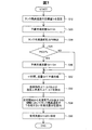
図2は、水素充填システム100が車両200の水素ガスタンク206に水素ガスを充填する際の予備充填の処理を示すフローチャートである。図2の処理は、制御装置130が水素充填システム100の各部を制御し、さらに車両200から必要な情報を取得することにより実行される。
A2. Pre-filling:
FIG. 2 is a flowchart showing a preliminary filling process when the
ステップS20において、制御装置130は、予備充填の際の水素ガスの流量QdをQLに設定する。本明細書において、流量は、単位時間当たりの質量で定められる。QLは、本実施形態では、12g/secである。なお、流量Qdのデフォルトの値は、図2の予備充填の処理の開始前にあらかじめ設定されていてもよい。
In step S20, the
ステップS30において、制御装置130は、予備充填直前の水素ガスタンク206内の圧力P0を取得する。具体的には、制御装置130は、圧力センサ207によって取得された水素ガスタンク206内の圧力を、通信機124を介して、車両200から取得する(図1参照)。なお、予備充填の流量を決定するためのタンク内の圧力の測定は、より前の時刻に行われることもできる。ただし、タンク内の圧力の測定から予備充填の開始までの時間は短い方が好ましい。
In step S30, the
ステップS35において、制御装置130は、圧力P0がしきい値Ps以上であるか否かを判定する。しきい値Psは、たとえば、5MPaである。ステップS35において、圧力P0がしきい値Ps以上である場合には(S35:Yes)、処理は、ステップS40に進む。圧力P0がしきい値Ps未満である場合には(S35:No)、処理は、ステップS50に進む。
In step S35, the
ステップS40において、制御装置130は、予備充填の際の水素ガスの流量QdをQLからQH(QH>QL)に設定しなおす。QHは、本実施形態では、35g/secである。
In step S40, the
このような態様とすることにより、システムの故障などによって、ステップS35,S40の処理が適切に行われなかった場合には、予備充填(ステップS50)は、流量QHよりも小さい流量QLで行われる。このため、最初にステップS20で流量QHが設定される態様に比べて、システムの消費エネルギーを低減することができる。 By setting it as such an aspect, when the process of step S35, S40 is not performed appropriately by failure of a system etc., preliminary filling (step S50) is performed by the flow volume QL smaller than the flow volume QH. . For this reason, the energy consumption of the system can be reduced compared to the aspect in which the flow rate QH is first set in step S20.
ステップS20〜S40の処理の結果、予備充填直前の水素ガスタンク206内の圧力P0がしきい値Ps未満である場合には、予備充填の際の水素ガスの流量Qdは、QLに設定され、予備充填直前の水素ガスタンク206内の圧力P0がしきい値Ps以上である場合には、予備充填の際の水素ガスの流量Qdは、QHに設定される。本実施形態においては、予備充填の際のタンクの圧力に応じた流量の区分は二つである(図2のS20参照)。しかし、予備充填の際のタンクの圧力に応じた流量の区分は、3区分、4区分など、3区分以上とすることもできる。
If the pressure P0 in the
ステップS50において、制御装置130は、設定された流量Qdで所定時間tの間、予備充填を行う。予備充填を行う時間tは、本実施形態では3秒である。予備充填を行っている間、圧力センサ207によって、水素ガスタンク206内の水素ガスの圧力が測定される(図1参照)。また、予備充填を行っている間、温度センサ208によって、水素ガスタンク206内の水素ガスの温度が測定される。
In step S50, the
ステップS55において、制御装置130は、予備充填を行っている時間tにおける圧力の上昇量ΔPに対する、予備充填を行っている時間tにおける温度の上昇量ΔT、すなわち、ΔT/ΔPを計算する。そして、制御装置130は、ΔT/ΔPがしきい値X1以上であるか否かを判定する。
In step S55, the
理想気体の圧力Pと温度Tは、気体の状態方程式PV=nRTを満たす。ここで、nは、気体の物質量を表す。Vは、気体の体積を表す。Rは、気体定数である。気体定数Rと、体積V(水素ガスタンク206の容積)とは、一定である。また、本実施形態の予備充填において単位時間当たりに水素ガスタンク206に充填される水素ガスの質量は、一定に制御されており(図2のS20,S40参照)、予備充填の時間tも一定である。このため、予備充填による水素ガスタンク206内の水素ガスの物質量の増分Δnは、車両および水素タンクによらず一定である。すると、ΔT/ΔPも、理想的には一定であるはずである。
The pressure P and temperature T of the ideal gas satisfy the gas state equation PV = nRT. Here, n represents the amount of a gaseous substance. V represents the volume of the gas. R is a gas constant. The gas constant R and the volume V (volume of the hydrogen gas tank 206) are constant. Further, the mass of the hydrogen gas filled in the
しかし、ΔT/ΔPは、個々の車両の水素タンクによって異なる。この要因の一つは、水素ガスの供給によって水素タンク内の水素ガスの温度が環境温度よりも高温になり、水素タンク内の水素ガスから水素タンクの壁面を介して外部に熱が放出されることである。この熱の放出の程度、すなわち、単位時間当たりに水素タンク内の水素ガスから外部に放出される熱の量は、個々の車両の水素タンクの形状や壁の厚さ、素材、配置などによって異なる。その結果、ΔT/ΔPは、個々の車両の水素タンクによって異なる。このため、図2のステップS55で得られるΔT/ΔPは、車両の水素タンクの放熱性能を反映する。ΔT/ΔPが小さいほど、その水素タンクは単位時間当たりに多くの熱を外部に放出するタンクである。 However, ΔT / ΔP varies depending on the hydrogen tank of the individual vehicle. One of the factors is that the temperature of the hydrogen gas in the hydrogen tank becomes higher than the environmental temperature due to the supply of the hydrogen gas, and heat is released from the hydrogen gas in the hydrogen tank to the outside through the wall of the hydrogen tank. That is. The degree of heat release, that is, the amount of heat released from the hydrogen gas in the hydrogen tank per unit time depends on the shape, wall thickness, material, and arrangement of the hydrogen tank of each vehicle. . As a result, ΔT / ΔP varies depending on the hydrogen tank of the individual vehicle. Therefore, ΔT / ΔP obtained in step S55 of FIG. 2 reflects the heat dissipation performance of the hydrogen tank of the vehicle. The smaller the ΔT / ΔP is, the more the hydrogen tank releases more heat per unit time.
一方、水素タンクの壁面を保護するため、水素ガスタンク206内の水素ガスの温度は、所定値(たとえば、85℃)以下に保つことが好ましい。たとえば、SAE J2601標準においても、水素タンクの温度は85℃以下に保つべきことが定められている。このため、水素タンクの温度を一定値以下に保つという条件下で、できるだけ短時間で水素の充填を完了しようとすると、以下の制約が生じる。すなわち、単位時間当たりに多くの熱を外部に放出する水素ガスタンク206Hに対しては、単位時間当たりに多くの水素ガスを充填することができる。一方、水素ガスタンク206Hに比べて単位時間当たりに少ない熱を外部に放出する水素ガスタンク206Lに対しては、水素ガスタンク206Hに比べて単位時間当たりに少ない水素ガスしか充填できない。
On the other hand, in order to protect the wall surface of the hydrogen tank, the temperature of the hydrogen gas in the
図2のステップS55において、ΔT/ΔPがしきい値X1以上である場合には(S55:Yes)、処理は、ステップS60に進む。ΔT/ΔPが大きいということは、タンクの単位時間当たりの放熱量が小さいということである。ステップS60において、制御装置130は、本充填の流量を決定する際に参照するマップとしてマップM1を採用する。マップM1は、他のマップM2,M3に比べて、同一条件下における出力流量が小さいマップである。
If ΔT / ΔP is greater than or equal to threshold value X1 in step S55 of FIG. 2 (S55: Yes), the process proceeds to step S60. A large ΔT / ΔP means that the amount of heat released per unit time of the tank is small. In step S60, the
ステップS55において、ΔT/ΔPがしきい値X1未満である場合には(S55:No)、処理は、ステップS65に進む。ステップS65では、制御装置130は、ΔT/ΔPがしきい値X2以上であるか否かを判定する(X2<X1)。
In step S55, when ΔT / ΔP is less than threshold value X1 (S55: No), the process proceeds to step S65. In step S65,
ステップS65において、ΔT/ΔPがしきい値X2以上である場合には(S65:Yes)、処理は、ステップS70に進む。ステップS70において、制御装置130は、本充填の流量を決定する際に参照するマップとしてマップM2を採用する。マップM2は、マップM3に比べて、同一条件下における出力流量が小さく、マップM1に比べて、同一条件下における出力流量が大きいマップである。
If ΔT / ΔP is equal to or greater than threshold value X2 in step S65 (S65: Yes), the process proceeds to step S70. In step S <b> 70, the
ステップS65において、ΔT/ΔPがしきい値X2未満である場合には(S65:No)、処理は、ステップS80に進む。ΔT/ΔPが小さいということは、タンクの単位時間当たりの放熱量が大きいということである。ステップS80において、制御装置130は、本充填の流量を決定する際に参照するマップとしてマップM3を採用する。マップM3は、他のマップM1,M2に比べて、同一条件下における出力流量が大きいマップである。
In step S65, if ΔT / ΔP is less than threshold value X2 (S65: No), the process proceeds to step S80. That ΔT / ΔP is small means that the heat radiation amount per unit time of the tank is large. In step S80, the
ステップS60,S70,S80で本充填における流量の決定に際して使用されべきマップが選択された後、図2の予備充填の処理は終了する。 After the map to be used for determining the flow rate in the main filling is selected in steps S60, S70, and S80, the preliminary filling process in FIG.
図3は、あるタンクを使用して、予備充填前の様々な圧力P0に対応する予備充填時の圧力上昇量ΔPを示したグラフである。予備充填の時間はt(は3秒)である。予備充填前の圧力P0がしきい値Psより小さい範囲にある場合は(図2のS35:No)、予備充填時の圧力上昇量ΔPは、実線のグラフG31で示される値となる。このとき、予備充填は、流量QL(本実施形態において12g/sec)で行われている。一方、予備充填前の圧力P0がしきい値Ps以上の範囲にある場合は(図2のS35:Yes)、予備充填時の圧力上昇量ΔPは、実線のグラフG32で示される値となる。このとき、予備充填は、流量QH(本実施形態において35g/sec)で行われている。 FIG. 3 is a graph showing a pressure increase amount ΔP at the time of preliminary filling corresponding to various pressures P0 before preliminary filling using a certain tank. The prefilling time is t (3 seconds). When the pressure P0 before preliminary filling is in a range smaller than the threshold value Ps (S35: No in FIG. 2), the pressure increase amount ΔP at the time of preliminary filling is a value indicated by a solid line graph G31. At this time, the preliminary filling is performed at a flow rate QL (12 g / sec in the present embodiment). On the other hand, when the pressure P0 before the preliminary filling is in the range equal to or higher than the threshold value Ps (S35 in FIG. 2: Yes), the pressure increase amount ΔP at the preliminary filling is a value indicated by the solid line graph G32. At this time, the preliminary filling is performed at a flow rate QH (35 g / sec in the present embodiment).
予備充填前の水素ガスタンク206内の圧力P0によらず、流量QLで予備充填を行う態様においては、予備充填時の圧力上昇量ΔPは、実線のグラフG31と破線のグラフG33で示される値となる。すなわち、水素ガスタンク206内の圧力P0が高くなるにつれて、圧力上昇量ΔPは、小さくなる。このため、ノイズに対して圧力上昇量ΔPが十分な値を取り得ず、正確に圧力上昇量ΔPを測定することが難しい。
In an embodiment in which the preliminary filling is performed at the flow rate QL regardless of the pressure P0 in the
しかし、本実施例においては、予備充填前の圧力P0がしきい値Ps以上の範囲にある場合は(図2のS35:No)、圧力P0がしきい値Ps未満の範囲にある場合の流量QLに比べて大きい流量QHで予備充填を行う。その結果、圧力上昇量ΔPをノイズに対して十分な値とすることができる(図3のG32参照)。よって、正確に圧力上昇量ΔPを測定することができる(図2のS55参照)。 However, in this embodiment, when the pressure P0 before preliminary filling is in the range equal to or higher than the threshold value Ps (S35: No in FIG. 2), the flow rate when the pressure P0 is in the range less than the threshold value Ps. Pre-filling is performed at a flow rate QH larger than QL. As a result, the pressure increase amount ΔP can be set to a value sufficient for noise (see G32 in FIG. 3). Therefore, the pressure increase amount ΔP can be accurately measured (see S55 in FIG. 2).
図4は、本実施形態において、予備充填前の圧力P0がしきい値Ps(5MPa)以上の値をとる場合の二つの水素ガスタンク206H,206LのΔT/ΔPを示したグラフである。単位時間当たりに多くの熱を外部に放出する水素ガスタンク206HのΔT/ΔPは、グラフG4Hで表される。水素ガスタンク206Hに比べて単位時間当たりに少ない熱を外部に放出する水素ガスタンク206LのΔT/ΔPは、グラフG4Lで表される。放熱性がよい水素ガスタンク206HのΔT/ΔPは、予備充填前の圧力P0が高い範囲(P0≧Ps。図2のS35参照)においても、放熱性が悪い水素ガスタンク206LのΔT/ΔPに対して十分低い値をとっていることが分かる。すなわち、放熱性がよい水素ガスタンク206HのΔT/ΔPが取り得る範囲と、放熱性が悪い水素ガスタンク206LのΔT/ΔPが取り得る範囲とは、重複していない。このため、本実施形態においては、図2のステップS55,S65の判定、言い換えればマップM1〜M3をそれぞれ適用すべき場合の区別(図2のS60,S70,S80参照)を、正確に行うことができる。 FIG. 4 is a graph showing ΔT / ΔP of the two hydrogen gas tanks 206H and 206L when the pressure P0 before the preliminary filling takes a value equal to or higher than the threshold value Ps (5 MPa) in the present embodiment. ΔT / ΔP of the hydrogen gas tank 206H that releases a lot of heat per unit time is represented by a graph G4H. ΔT / ΔP of the hydrogen gas tank 206L that releases less heat per unit time than the hydrogen gas tank 206H is represented by a graph G4L. [Delta] T / [Delta] P of the heat radiation is good hydrogen gas tank 206H, the pressure P0 before the preliminary filling range higher in (P0 ≧ Ps. Referring S35 in FIG. 2), with respect to [Delta] T / [Delta] P of the poor heat dissipation hydrogen gas tank 206 L It can be seen that the value is sufficiently low. That is, the range that can be taken by ΔT / ΔP of the hydrogen gas tank 206H with good heat dissipation does not overlap with the range that can take ΔT / ΔP of the hydrogen gas tank 206L with poor heat dissipation. For this reason, in the present embodiment, the determination of steps S55 and S65 in FIG. 2, in other words, the distinction when the maps M1 to M3 are to be applied, respectively (see S60, S70, and S80 in FIG. 2) is accurately performed. Can do.
図5は、予備充填前の水素タンク内の圧力P0によらず流量QLで予備充填を行う態様において、予備充填前の圧力P0がしきい値Ps(5MPa)以上の値をとる場合の二つの水素ガスタンク206H,206LのΔT/ΔPを示したグラフである。単位時間当たりに多くの熱を外部に放出する水素ガスタンク206HのΔT/ΔPは、グラフG5Hで表される。水素ガスタンク206Hに比べて単位時間当たりに少ない熱を外部に放出する水素ガスタンク206LのΔT/ΔPは、グラフG5Lで表される。 FIG. 5 shows two cases where the pressure P0 before the preliminary filling takes a value equal to or higher than the threshold value Ps (5 MPa) in the aspect in which the preliminary charging is performed at the flow rate QL regardless of the pressure P0 in the hydrogen tank before the preliminary charging. It is the graph which showed (DELTA) T / (DELTA) P of the hydrogen gas tanks 206H and 206L. ΔT / ΔP of the hydrogen gas tank 206H that releases a lot of heat per unit time is represented by a graph G5H. ΔT / ΔP of the hydrogen gas tank 206L that releases less heat per unit time than the hydrogen gas tank 206H is represented by a graph G5L.
グラフG5Hに示されるように、予備充填前の内の圧力P0がPs(5MPa)近傍にあるときには、放熱性がよい水素ガスタンク206HのΔT/ΔPは、0.2以上の値をとる。一方、グラフG5Lに示されるように、予備充填前の内の圧力P0が大きいときには、放熱性が悪い水素ガスタンク206LのΔT/ΔPは、0.2近傍の値をとる。そして、予備充填前の内の圧力P0が5MPa近傍にあるときの放熱性がよい水素ガスタンク206HのΔT/ΔPよりも低い値を、放熱性が悪い水素ガスタンク206LのΔT/ΔPは、取り得る(グラフG5Lの右端およびグラフG5Hの左端参照)。このため、予備充填前の水素タンク内の圧力P0によらず流量QLで予備充填を行う態様においては、ΔT/ΔPの大きさに基づくマップの選択(本実施形態の図2のステップS55,S65参照)を適切に行うことが容易ではない。そして、測定値にはノイズが含まれることから、この態様においては、ΔT/ΔPの大きさに基づくマップの選択(図2のステップS60,S70,S80参照)を適切に行うことは、事実上は困難である。 As shown in the graph G5H, when the pressure P0 before the preliminary filling is in the vicinity of Ps (5 MPa), ΔT / ΔP of the hydrogen gas tank 206H having good heat dissipation has a value of 0.2 or more. On the other hand, as shown in the graph G5L, when the pressure P0 before the preliminary filling is large, ΔT / ΔP of the hydrogen gas tank 206L with poor heat dissipation takes a value in the vicinity of 0.2. Then, ΔT / ΔP of the hydrogen gas tank 206L with poor heat dissipation can take a value lower than ΔT / ΔP of the hydrogen gas tank 206H with good heat dissipation when the pressure P0 before prefilling is in the vicinity of 5 MPa ( (See right end of graph G5L and left end of graph G5H). For this reason, in the mode in which the preliminary filling is performed at the flow rate QL regardless of the pressure P0 in the hydrogen tank before the preliminary filling, map selection based on the magnitude of ΔT / ΔP (steps S55 and S65 in FIG. 2 of the present embodiment). It is not easy to do appropriately. Since the measurement value includes noise, in this aspect, it is practically appropriate to select a map based on the magnitude of ΔT / ΔP (see steps S60, S70, and S80 in FIG. 2). It is difficult.
これに対して、本実施形態においては、予備充填における流量を、水素ガスタンクの圧力によって切り換えているため、マップM1〜M3をそれぞれ適用すべき場合の区別(図2のS60,S70,S80参照)を、正確に行うことができる(図4参照)。 On the other hand, in this embodiment, since the flow rate in the preliminary filling is switched depending on the pressure of the hydrogen gas tank, distinction between cases where the maps M1 to M3 are to be applied (see S60, S70, and S80 in FIG. 2). Can be performed accurately (see FIG. 4).
なお、予備充填における単位時間あたりの流量を増加させることによって、図4のように、放熱性が異なるタンクのΔT/ΔPの違いが増大する理由は以下のようなものである。すなわち、単位時間あたりの流量を増加させることによって、予備充填における圧力の上昇量ΔPが大きくなる。ΔPが大きいということは、予備充填によって水素ガスタンク206へ投入されるエネルギー、すなわち熱量が大きいということである。水素ガスタンク206へ投入される熱量が増えると、放熱性の良いタンクが外部に放出する熱量と、放熱性の悪いタンクが外部に放出する熱量との差も大きくなる。その結果、タンクの放熱性の良悪の差がΔT/ΔPに大きく現れる。
The reason why the difference in ΔT / ΔP of the tanks having different heat dissipation properties increases as shown in FIG. 4 by increasing the flow rate per unit time in the preliminary filling is as follows. That is, by increasing the flow rate per unit time, the pressure increase amount ΔP in the preliminary filling increases. A large ΔP means that the energy input to the
図6は、本充填における水素ガスの充填流量を設定する処理を示すフローチャートである。図6の処理は、制御装置130が水素充填システム100の各部を制御し、さらに車両200から必要な情報を取得することにより実行される。予備充填後であって本充填の直前に、図2の処理によって選択されたマップ(図2のステップS60、S70、およびS80参照)を使用して、図6に示すように、本充填における水素ガスの充填流量が設定される。
FIG. 6 is a flowchart showing a process for setting the filling flow rate of hydrogen gas in the main filling. The processing in FIG. 6 is executed by the
ステップS110において、制御装置130は、本充填直前の水素ガスタンク206内の圧力P1を取得する。また、制御装置130は、本充填直前の水素ガスタンク206内の温度T1を取得する。具体的には、制御装置130は、通信機124を介して、車両200から水素ガスタンク206内の圧力および温度を取得する(図1参照)。
In step S110, the
ステップS120において、制御装置130は、配管118内の水素ガスの温度Tgを取得する。具体的には、制御装置130は、温度センサ121から、配管118内の水素ガスの温度Tgを取得する(図1参照)。なお、本充填の流量を決定するためのタンク内の圧力および温度、ならびにタンクに供給すべきガスの温度の測定は、より前の時刻に行われることもできる。ただし、それらのパラメータの測定から本充填の開始までの時間は短い方が好ましい。
In step S120, the
ステップS130において、制御装置130は、図2の処理で選択されたマップM1〜M3のうちの一つを使用して、水素ガスタンク206内の圧力P1、温度T1、および充填される水素ガスの温度Tgに基づいて、本充填における水素ガスの流量を決定する。
In step S <b> 130, the
本充填では、図6の処理で決定された流量で、水素ガスの充填が行われる。なお、本実施形態では、水素ガスタンク206への水素ガスの充填は、水素ガスタンク206内の水素ガスの圧力が70MPaとなるまで行われる。
In the main filling, the hydrogen gas is filled at the flow rate determined in the process of FIG. In the present embodiment, the
このような態様とすることで、あらかじめ設定された温度を超えて水素ガスタンク206が高温になる事態を避けつつ、短時間で水素ガスタンク206に水素ガスを充填することができる。
By setting it as such an aspect,
B.実施形態2:
B1.予備充填および流量の決定:
実施形態2においては、予備充填の結果に基づく本充填の流量の決定方法(図2のステップS55〜S80、ならびに図6参照)と、本充填における充填の制御方法とが、実施形態1とは異なる。そして、実施形態2の水素充填システム100は、マップM1〜M3(図1参照)を備えていない。実施形態2の他の点は、実施形態1と同じである。
B. Embodiment 2:
B1. Pre-fill and flow rate determination:
In the second embodiment, the main filling flow rate determination method based on the result of the preliminary filling (see steps S55 to S80 in FIG. 2 and FIG. 6) and the filling control method in the main filling are different from the first embodiment. Different. And
図7は、水素充填システム100が車両200の水素ガスタンク206に水素ガスを充填する際の予備充填の処理および本充填の流量を決定する処理を示すフローチャートである。図7の処理は、制御装置130が水素充填システム100の各部を制御し、さらに車両200から必要な情報を取得することにより実行される。図7の処理は、実施形態1における図2の処理および図6の処理に相当する。
FIG. 7 is a flowchart showing a preliminary filling process and a process for determining the main filling flow rate when the
ステップS12において、制御装置130は、水素ガスタンク206の上限温度Trを設定する。上限温度Trは、たとえば、SAE J2601標準で定められた温度85℃から所定量だけ下の温度とすることができる。
In step S <b> 12, the
図7のステップS20〜S40の処理は、実施形態1の図2のステップS20〜S40の処理と同じである。 The processing in steps S20 to S40 in FIG. 7 is the same as the processing in steps S20 to S40 in FIG.
ステップS52において、制御装置130は、設定された流量Qdで所定時間t1の間、予備充填を行う。なお、予備充填を行う時間t1は、実施形態1において予備充填を行う時間tと同じであってもよいし、異なっていてもよい。予備充填を行っている間、圧力センサ207によって、水素ガスタンク206内の水素ガスの圧力が測定される(図1参照)。また、予備充填を行っている間、温度センサ208によって、水素ガスタンク206内の水素ガスの温度が測定される。
In step S52, the
ステップS92において、制御装置130は、予備充填を行っている時間t1における圧力の上昇量ΔPに対する、予備充填を行っている時間t1における温度の上昇量ΔT、すなわち、ΔT/ΔPを計算する。また、制御装置130は、予備充填における単位時間当たりの温度の上昇量ΔT/t1を計算する。
In step S92, the
実施形態1の説明で述べたように、ΔT/ΔPは、水素ガスタンク206の放熱のしやすさを表す。すなわち、ΔT/ΔPが小さいほど、水素タンクは単位時間当たりに多くの熱を外部に放出する。また、単位時間当たりの温度の上昇量ΔT/t1は、水素ガスタンク206の温度変化のしやすさを表す。
As described in the description of the first embodiment, ΔT / ΔP represents the ease of heat dissipation from the
水素ガスタンク206において水素ガスが充填されると、水素ガスタンク206の充填口から水素ガスタンク206の内部に向かって、水素ガスが吹き込まれる。すると、充填口から水素ガスタンク206の奥に向かう向きに水素ガスが断熱圧縮されて、水素ガスの温度が上昇する。その結果、水素ガスの充填によって、充填口と向かい合う側の端部近傍に存在する水素ガスが、最も高温となる。そして、水素ガスの充填が終了した後、水素ガスタンク206内の温度分布のムラが解消され、水素ガスタンク206内の温度がほぼ均一となるまでには、ある程度の時間を要する。
When hydrogen gas is filled in the
温度センサ208が、充填口と向かい合う側の端部近傍以外の場所、たとえば、充填口の近傍に設けられている態様においては、温度センサ208近傍の水素ガスの温度は、充填終了時には、充填口と向かい合う側の端部の水素ガスよりも低い。そして、温度センサ208近傍の水素ガスの温度は、ガスの充填終了後、水素ガスタンク206内の温度が均一になるにつれて、充填終了時よりもさらに上昇する。ガスの充填終了後、温度センサ208近傍の水素ガスの温度が最高値に達するまでの時間は、水素ガスタンク206の温度変化のしやすさ(熱伝導率)に依存する。図7のステップS92で計算したΔT/t1は、水素ガスタンク206の温度変化のしやすさを表すため、水素ガスタンク206の温度上昇の時間遅れの目安となる。
In a mode in which the
図7のステップS94において、制御装置130は、ステップS92で得たパラメータΔT/ΔP、ΔT/t1に基づいて、水素ガスタンク206の温度変化に関するモデルを作成する。そして、制御装置130は、本充填における水素ガスの充填開始から、水素ガスの充填終了時刻に時間t2を加えた時刻までの水素ガスタンク206の温度変化を計算する。すなわち、本実施形態では、制御装置130は、モデル規範形制御を行う。なお、時間t2は、本実施形態では、60分とする。
In step S94 of FIG. 7, the
ステップS94において、制御装置130は、上記のモデルを使用して、水素ガスの充填開始から、水素ガスの充填終了時刻に時間t2を加えた時刻までの間に、水素ガスタンク206の温度がステップS12で定めた上限温度Trを超えないような流量であって、できるだけ多い流量Q0を、計算する。
In step S94, using the above model, the
ステップS96において、制御装置130は、ステップS94で得られた流量Q0を、本充填の際の流量として設定する。
In step S96, the
実施形態2においては、以上の処理で、予備充填、および本充填の際の流量の決定が行われる。このような態様とすることにより、水素ガスタンク206内の水素ガスの温度分布(ばらつき)および充填完了後までも含めた温度変化を考慮して、短時間で充填を完了できる流量Q0を、本充填の流量Qとして設定することができる。
In the second embodiment, the flow rate for the preliminary filling and the main filling is determined by the above processing. By adopting such an aspect, considering the temperature distribution (variation) of the hydrogen gas in the
また、実施形態2においては、実施形態1と同様の理由から(図7のステップS20〜S40参照)、予備充填における圧力上昇量を正確に測定することができる(図3参照)。このため、正確なΔT/ΔPに基づいて正確なモデル化を行うことができる(図4、ならびに図7のS92,S94参照)。その結果、タンクの温度が上限温度Trを超えないような流量であって、できるだけ多い適正な流量Q0を、計算することができる。 Further, in the second embodiment, for the same reason as in the first embodiment (see steps S20 to S40 in FIG. 7), the pressure increase amount in the preliminary filling can be accurately measured (see FIG. 3). Therefore, accurate modeling can be performed based on accurate ΔT / ΔP (see FIG. 4 and S92 and S94 in FIG. 7). As a result, it is possible to calculate an appropriate flow rate Q0 as much as possible, which is a flow rate at which the tank temperature does not exceed the upper limit temperature Tr.
B2.本充填:
実施形態1においては、本充填は、図6の処理で定められた一定の流量で行われる。しかし、実施形態2の本充填においては、水素ガスの流量は、図7の処理で定められた流量に基づいて行われるものの、モデルから得られた温度の予測値Tm、および測定された温度T2に基づいて、変更(すなわち制御)される。
B2. Book filling:
In the first embodiment, the main filling is performed at a constant flow rate determined by the process of FIG. However, in the main filling of the second embodiment, the flow rate of the hydrogen gas is performed based on the flow rate determined in the process of FIG. 7, but the predicted value Tm of the temperature obtained from the model and the measured temperature T2 Is changed (ie, controlled).
図8は、水素充填システム100が車両200の水素ガスタンク206に水素ガスを充填する際の本充填の処理を示すフローチャートである。図8の処理は、制御装置130が水素充填システム100の各部を制御し、さらに車両200から必要な情報を取得することにより実行される。
FIG. 8 is a flowchart showing the main filling process when the
ステップS220において、制御装置130は、本充填を開始する。その際、制御装置130は、図7の処理で定められた流量Qに基づいて、流量調整弁115を制御する。
In step S220, the
ステップS230において、制御装置130は、図7のステップS92で得たパラメータΔT/ΔP、ΔT/t1に基づく水素ガスタンク206の温度変化に関するモデルに基づいて(図7のS94参照)、本充填開始後、時間tが経過したときの予測温度Tmを計算する。ステップS230の処理は、図7のS94の処理と同様、モデル規範形制御である。
In step S230, the
ステップS240において、制御装置130は、本充填開始後、時間tが経過したときに、水素ガスタンク206内の温度T2を取得する。具体的には、制御装置130は、本充填開始後、時間tが経過したときに温度センサ208によって取得された水素ガスタンク206内の温度T2を、通信機124を介して、車両200から取得する(図1参照)。
In step S240, the
ステップS245において、制御装置130は、水素ガスタンク206内の温度の測定値T2と、予測温度Tmと、のずれ(差の絶対値)が、しきい値Xより大きいか否かを判定する。測定値T2と予測温度Tmのずれがしきい値X以下である場合(S245:No)、処理はステップS275に進む。測定値T2と予測温度Tmのずれがしきい値Xより大きい場合(S245:Yes)、処理はステップS255に進む。
In step S245, the
ステップS255において、制御装置130は、水素ガスタンク206内の温度の測定値T2が、予測温度Tmより高いか否かを判定する。測定値T2が予測温度Tmより大きい場合(S255:Yes)、処理はステップS260に進む。ステップS260において、制御装置130は、水素ガスの流量QをY(Y<Q)だけ減少させる。
In step S255, the
一方、ステップS255において、測定値T2が予測温度Tm以下である場合(S255:No)、処理はステップS270に進む。ステップS270において、制御装置130は、水素ガスの流量QをYだけ増加させる。
On the other hand, when the measured value T2 is equal to or lower than the predicted temperature Tm in step S255 (S255: No), the process proceeds to step S270. In step S270, the
ステップS275において、制御装置130は、本充填を完了すべきか否かを判断する。より具体的には、水素ガスタンク206内の圧力が、所定値(本実施形態において、70MPa)に達したか否かを判定する。水素ガスタンク206内の圧力が、所定値未満である場合には(S275:No)、処理は、ステップS220に戻る。ステップS220では、本充填が継続される。水素ガスタンク206内の圧力が、所定値に達した場合には(S275:Yes)、処理は、終了する。
In step S275,
本実施形態においては、ステップS245〜S270の処理を行うことにより、以下のような効果を奏することができる。すなわち、本充填において、モデルに基づいて最高温度がTr(図7のS12参照)を超えないようにするため、各時刻における水素ガスタンク206内の温度の測定値T2が予測値Tm近傍となるようにしつつ(図8のS245,S260)、流量をできるだけ多くなるように制御することができる(図8のS270)。このため、水素ガスタンク206を保護しつつ、短時間で水素ガスの充填を行うことができる。
In the present embodiment, the following effects can be achieved by performing the processing of steps S245 to S270. That is, in the main filling, in order to prevent the maximum temperature from exceeding Tr (see S12 in FIG. 7) based on the model, the measured value T2 of the temperature in the
C.実施形態3:
実施形態3においては、予備充填の流量の設定方法(図2のステップS20,S35参照)が、実施形態1とは異なる。実施形態3の他の点は、実施形態1と同じである。
C. Embodiment 3:
In the third embodiment, the setting method of the pre-filling flow rate (see steps S20 and S35 in FIG. 2) is different from that in the first embodiment. Other points of the third embodiment are the same as those of the first embodiment.
図9は、水素充填システム100が車両200の水素ガスタンク206に水素ガスを充填する際の予備充填の処理を示すフローチャートである。図9の処理は、制御装置130が水素充填システム100の各部を制御し、さらに車両200から必要な情報を取得することにより実行される。図9の処理は、実施形態1における図2の処理に相当する。図9において、図2の処理と同じ処理には、図2のステップの番号と同じ番号を付す。
FIG. 9 is a flowchart showing a preliminary filling process when the
実施形態3においては、最初に予備充填の際の水素ガスの流量QdをQLに設定する処理は行われない(図2のS20参照)。そして、ステップS35において、水素ガスタンク206の圧力P0がしきい値Ps未満である場合には(S35:No)、処理は、ステップS44に進む。
In the third embodiment, the process of first setting the flow rate Qd of hydrogen gas at the time of preliminary filling to QL is not performed (see S20 in FIG. 2). In step S35, if the pressure P0 of the
ステップS44において、制御装置130は、予備充填の際の水素ガスの流量QdをQLに設定する。QLは、本実施形態では、12g/secである。ステップS44の処理は、実施形態1の図2のS20の処理と同じである。その後、処理は、ステップS50に進む。
In step S44, the
図9のステップS50以下の処理は、図2のステップS50以下の処理と同じである。 The processing after step S50 in FIG. 9 is the same as the processing after step S50 in FIG.
このような態様とすれば、簡易な処理で(ステップS35,S40,S44参照)、予備充填における圧力変化を正確に測定することができる。その結果、実施形態1と同様に、本充填の流量を決定する際に使用するマップの選択(ステップS55,S65参照)を適切に行うことができる。 If it is set as such an aspect, the pressure change in preliminary filling can be measured correctly by simple processing (refer to Steps S35, S40, and S44). As a result, as in the first embodiment, it is possible to appropriately select a map (see Steps S55 and S65) to be used when determining the main filling flow rate.
D.変形例:
D1.変形例1:
予備充填の際のガスの充填の流量は、予備充填中に変化してもよい。ただし、予備充填開始前のタンク内の圧力が第1の範囲内であるときの予備充填の流量の平均値は、予備充填開始前のタンク内の圧力が第1の範囲と重複せず第1の範囲よりも高い第2の範囲内であるときの予備充填の流量の平均値よりも、低いことが好ましい。
D. Variations:
D1. Modification 1:
The flow rate of gas filling during pre-filling may vary during pre-filling. However, the average value of the pre-fill flow rate when the pressure in the tank before the start of pre-filling is within the first range is the first value because the pressure in the tank before the start of pre-fill does not overlap with the first range. It is preferable that it is lower than the average value of the flow rate of the pre-filling when it is in the second range higher than the range.
D2.変形例2:
予備充填の流量を切り換える圧力のしきい値Psは、2Mpa、8MPaなど、他の値とすることもできる。ただし、予備充填の流量を切り換える圧力のしきい値Psは、1〜10Mpaとすることが好ましく、3〜7MPaとすることが寄り好ましい。予備充填の流量を切り換える圧力のしきい値をそのような値とすることにより、最大70MPaの圧力までガスを充填するタンクの予備充填において、圧力上昇量を正確に測定することができる。
D2. Modification 2:
The pressure threshold value Ps for switching the pre-filling flow rate can be set to other values such as 2 Mpa and 8 MPa. However, the pressure threshold value Ps for switching the pre-filling flow rate is preferably 1 to 10 MPa, and more preferably 3 to 7 MPa. By setting the threshold value of the pressure for switching the flow rate of the preliminary filling to such a value, the amount of pressure increase can be accurately measured in the preliminary filling of the tank filled with the gas up to a pressure of 70 MPa.
D3.変形例3:
水素ガスタンク206内のガスの温度および圧力の測定は、予備充填の期間中の異なる二つの時刻について行われればよい。ただし、予備充填における温度の上昇量ΔTと圧力の上昇量ΔPを使用して、本充填の流量量を決定する際のΔTおよびΔPの測定時間は、同じ時間区間である。
D3. Modification 3:
The temperature and pressure of the gas in the
D4.変形例4:
予備充填の際に取得される圧力の上昇量ΔPおよび温度の上昇量ΔTは、予備充填を行っている時間t1のうちの一部の時間区間における圧力の上昇量および温度の上昇量とすることもできる。予備充填の開始直後の所定の時間区間、および予備充填の終了直前の所定の時間区間を除いて圧力の上昇量および温度の上昇量を測定することにより、ノイズの少ない測定を行うことができる。
D4. Modification 4:
The pressure increase amount ΔP and the temperature increase amount ΔT acquired at the time of preliminary filling are the pressure increase amount and the temperature increase amount in a part of the time interval of the pre-filling time t1. You can also. By measuring the amount of increase in pressure and the amount of increase in temperature except for a predetermined time interval immediately after the start of pre-filling and a predetermined time interval immediately before the end of pre-filling, measurement with less noise can be performed.
D5.変形例5:
予備充填における単位時間当たりの温度の上昇量は、予備充填中の他の時間区間(一部の時間区間)について計算されてもよい。ただし、より長い時間区間の温度変化を使用して単位時間当たりの温度の上昇量を計算することが好ましい。そのようにして得た単位時間当たりの温度の上昇量は、短い時間区間の局所的な温度変化の影響をより受けにくいためである。
D5. Modification 5:
The amount of temperature increase per unit time in the pre-filling may be calculated for other time intervals (partial time intervals) during the pre-filling. However, it is preferable to calculate the amount of increase in temperature per unit time using a temperature change in a longer time interval. This is because the increase in temperature per unit time obtained in this way is less susceptible to local temperature changes in a short time interval.
D6.変形例6:
本充填の流量は、ΔT/ΔPを使用する方法以外の、予備充填における圧力上昇量と温度上昇量とを使用した他の方法で定めることもできる。
D6. Modification 6:
The flow rate of the main filling can be determined by another method using the pressure increase amount and the temperature increase amount in the preliminary filling other than the method using ΔT / ΔP.
D7.変形例7:
本充填の流量の決定は、車両の制御装置や、ガス充填システムの制御部にデータを提供しうる外部の構成など、他の構成が行ってもよい。
D7. Modification 7:
The determination of the flow rate of the main filling may be performed by other configurations such as an external configuration capable of providing data to the vehicle control device or the control unit of the gas filling system.
D8.変形例8:
上記実施形態1においては、本充填は、一定流量で行われるものとし、上記実施形態1においては、本充填の際の水素ガスの充填の流量は一定である。しかし、本充填の際のガスの充填の流量は、本充填中に変化してもよい。たとえば、予備充填に基づいて定めた流量に基づいて本充填を開始し、その後、測定されたパラメータに応じて流量を変更してもよい(実施形態2の図8参照)。
D8. Modification 8:
In the first embodiment, the main filling is performed at a constant flow rate. In the first embodiment, the flow rate of the hydrogen gas filling during the main filling is constant. However, the flow rate of gas filling during the main filling may change during the main filling . For example, the main filling may be started based on the flow rate determined based on the preliminary filling, and then the flow rate may be changed according to the measured parameter (see FIG. 8 of the second embodiment).
本発明は、上述の実施形態や実施例、変形例に限られるものではなく、その趣旨を逸脱しない範囲において種々の構成で実現することができる。例えば、発明の概要の欄に記載した各形態中の技術的特徴に対応する実施形態、実施例、変形例中の技術的特徴は、上述の課題の一部又は全部を解決するために、あるいは、上述の効果の一部又は全部を達成するために、適宜、差し替えや、組み合わせを行うことが可能である。また、その技術的特徴が本明細書中に必須なものとして説明されていなければ、適宜、削除することが可能である。 The present invention is not limited to the above-described embodiments, examples, and modifications, and can be realized with various configurations without departing from the spirit thereof. For example, the technical features in the embodiments, examples, and modifications corresponding to the technical features in each embodiment described in the summary section of the invention are to solve some or all of the above-described problems, or In order to achieve part or all of the above effects, replacement or combination can be performed as appropriate. Further, if the technical feature is not described as essential in the present specification, it can be deleted as appropriate.
100…水素充填システム
112…ガス容器
113…圧縮機
114…蓄圧容器
115…流量調整弁
116…流量計
117…プレクーラ
118…配管
119…ガス充填ノズル
121…温度センサ
122…圧力センサ
123…外気温センサ
124…通信機
130…制御装置
200…車両
203…レセプタクル
204…配管
205…逆止弁
206…水素ガスタンク
207…圧力センサ
208…温度センサ
210…通信機
230…制御装置
M1〜M3…マップ
DESCRIPTION OF
Claims (7)
前記タンク内の圧力を取得する圧力取得部と、
前記タンク内の温度を取得する温度取得部と、
前記ガス供給部を制御して、前記タンクにガスを供給する第1の充填を行わせ、前記ガス供給部を制御して、前記第1の充填中の所定時間における前記タンク内の圧力の変化と前記タンク内の温度の変化の比に基づいて決定された流量に基づき、前記タンクにガスを供給する第2の充填を行わせる制御部と、を備え、
前記制御部は、
前記第1の充填の前の前記タンク内の圧力が第1の圧力である場合に、第1の流量で前記第1の充填を行わせ、
前記第1の充填の前の前記タンク内の圧力が前記第1の圧力より大きい第2の圧力である場合に、前記第1の流量よりも大きい第2の流量で前記第1の充填を行わせる、ガス供給部を制御するシステム。 A system for controlling a gas supply unit for supplying gas to a tank,
A pressure acquisition unit for acquiring the pressure in the tank;
A temperature acquisition unit for acquiring the temperature in the tank;
The gas supply unit is controlled to perform a first filling to supply gas to the tank, and the gas supply unit is controlled to change the pressure in the tank during a predetermined time during the first filling. And a controller for performing a second filling for supplying gas to the tank based on a flow rate determined based on a ratio of a change in temperature in the tank,
The controller is
If the pressure in the tank before the first filling is the first pressure, the first filling is performed at a first flow rate;
When the pressure in the tank before the first filling is a second pressure larger than the first pressure, the first filling is performed at a second flow rate larger than the first flow rate. System that controls the gas supply.
前記制御部は、
前記第1の充填の前の前記タンク内の圧力が、しきい値より小さい場合に、前記第1の充填における流量を前記第1の流量に設定し、
前記第1の充填の前の前記タンク内の圧力が、前記しきい値より大きい場合に、前記第1の充填における流量を前記第2の流量に設定する、システム。 The system of claim 1, comprising:
The controller is
If the pressure in the tank before the first filling is less than a threshold, set the flow rate in the first filling to the first flow rate,
A system for setting a flow rate in the first filling to the second flow rate when a pressure in the tank before the first filling is larger than the threshold value.
前記制御部は、
前記タンク内の圧力に応じた前記第1の充填における流量の設定に先立って、前記第1の充填における流量を前記第1の流量に設定する、システム。 The system according to claim 1 or 2, wherein
The controller is
Prior to setting of the flow rate in the first filling according to the pressure in the tank, the system sets the flow rate in the first filling to the first flow rate.
前記しきい値は、1〜10MPaの範囲内にある、システム。 The system of claim 2, comprising:
The system wherein the threshold is in the range of 1-10 MPa.
前記制御部は、
前記第1の充填中の前記所定時間における前記タンク内の前記圧力の変化ΔPに対する前記所定時間における前記タンク内の前記温度の変化ΔTが、第1の範囲内にあるとき、前記第2の充填前の前記タンク内の温度と圧力とに基づいてガスの流量を定める第1のマップに従って、前記第2の充填におけるガスの流量を設定し、
前記圧力の変化ΔPに対する前記温度の変化ΔTが、前記第1の範囲よりも小さい第2の範囲内にあるとき、前記第2の充填前の前記タンク内の温度と圧力とに基づいてガスの流量を定める第2のマップであって、同一の入力パラメータに対して前記第1のマップよりも大きい流量を定める第2のマップに従って、前記第2の充填におけるガスの流量を設定する、システム。 The system according to any one of claims 1 to 4,
The controller is
The second filling when the temperature change ΔT in the tank at the predetermined time relative to the pressure change ΔP in the tank at the predetermined time during the first filling is within a first range; Setting the gas flow rate in the second filling according to a first map that determines the gas flow rate based on the previous temperature and pressure in the tank;
When the temperature change ΔT with respect to the pressure change ΔP is in a second range that is smaller than the first range, the gas is changed based on the temperature and pressure in the tank before the second filling. A system that sets a gas flow rate in the second filling according to a second map that defines a flow rate, wherein the second map defines a flow rate that is greater than the first map for the same input parameter.
前記制御部は、
前記第1の充填中の前記所定時間における前記タンク内の前記圧力の変化ΔPに対する前記所定時間における前記タンク内の前記温度の変化ΔTと、前記第1の充填中の単位時間当たりの前記タンク内の温度の変化と、に基づいて、前記第2の充填におけるガスの流量を設定し、
前記圧力の変化ΔPに対する前記温度の変化ΔTと、前記単位時間当たりの温度の変化と、に基づいて定められる前記第2の充填中の前記タンク内の温度の予測値と、前記第2の充填中の前記タンク内の温度と、に基づいて、前記第2の充填におけるガスの流量を制御する、システム。 The system according to any one of claims 1 to 4,
The controller is
The temperature change ΔT in the tank at the predetermined time relative to the pressure change ΔP in the tank at the predetermined time during the first filling, and the tank per unit time during the first filling. And setting the gas flow rate in the second filling based on the change in temperature of
A predicted value of the temperature in the tank during the second filling determined based on the temperature change ΔT relative to the pressure change ΔP and the temperature change per unit time; and the second filling A system for controlling a flow rate of the gas in the second filling based on a temperature in the tank inside.
(a)タンクにガスを供給する第1の充填を行う工程と、
(b)前記第1の充填中の所定時間における前記タンク内の圧力の変化と前記タンク内の温度の変化の比に基づいて決定された流量に基づき、前記タンクにガスを供給する第2の充填を行う工程と、を備え、
前記工程(a)は、
前記第1の充填の前の前記タンク内の圧力が第1の圧力である場合に、第1の流量で前記第1の充填を行い、
前記第1の充填の前の前記タンク内の圧力が前記第1の圧力より大きい第2の圧力である場合に、前記第1の流量よりも大きい第2の流量で前記第1の充填を行う工程である、タンクにガスを充填する方法。 A method of filling a tank with gas,
(A) performing a first filling to supply gas to the tank;
(B) a second gas supplying gas to the tank based on a flow rate determined based on a ratio between a change in pressure in the tank and a change in temperature in the tank at a predetermined time during the first filling; And a step of filling,
The step (a)
When the pressure in the tank before the first filling is the first pressure, the first filling is performed at a first flow rate;
When the pressure in the tank before the first filling is a second pressure larger than the first pressure, the first filling is performed at a second flow rate larger than the first flow rate. A method of filling a tank with gas, which is a process.
Priority Applications (4)
| Application Number | Priority Date | Filing Date | Title |
|---|---|---|---|
| JP2014131064A JP6001600B2 (en) | 2014-06-26 | 2014-06-26 | System for controlling gas supply unit and gas filling method |
| CN201510354130.XA CN105318184B (en) | 2014-06-26 | 2015-06-24 | The system for controlling gas supply unit |
| DE102015110263.3A DE102015110263B4 (en) | 2014-06-26 | 2015-06-25 | System for controlling a gas supply unit |
| US14/749,789 US10443784B2 (en) | 2014-06-26 | 2015-06-25 | System for controlling gas supply unit |
Applications Claiming Priority (1)
| Application Number | Priority Date | Filing Date | Title |
|---|---|---|---|
| JP2014131064A JP6001600B2 (en) | 2014-06-26 | 2014-06-26 | System for controlling gas supply unit and gas filling method |
Publications (3)
| Publication Number | Publication Date |
|---|---|
| JP2016008693A JP2016008693A (en) | 2016-01-18 |
| JP2016008693A5 JP2016008693A5 (en) | 2016-03-17 |
| JP6001600B2 true JP6001600B2 (en) | 2016-10-05 |
Family
ID=54839970
Family Applications (1)
| Application Number | Title | Priority Date | Filing Date |
|---|---|---|---|
| JP2014131064A Active JP6001600B2 (en) | 2014-06-26 | 2014-06-26 | System for controlling gas supply unit and gas filling method |
Country Status (4)
| Country | Link |
|---|---|
| US (1) | US10443784B2 (en) |
| JP (1) | JP6001600B2 (en) |
| CN (1) | CN105318184B (en) |
| DE (1) | DE102015110263B4 (en) |
Families Citing this family (21)
| Publication number | Priority date | Publication date | Assignee | Title |
|---|---|---|---|---|
| EP3174071B1 (en) * | 2015-11-30 | 2018-11-14 | General Electric Technology GmbH | Method and installation for filling a gas-insulated switchgear comprising a mixture of (cf3)2cfcn and co2 |
| DE102017204672A1 (en) * | 2017-03-21 | 2018-09-27 | Robert Bosch Gmbh | Method and system for refueling a vehicle with hydrogen |
| DK179310B1 (en) * | 2017-05-22 | 2018-04-23 | Nel Hydrogen As | Method of refueling a hydrogen vehicle |
| DK179295B1 (en) * | 2017-05-22 | 2018-04-16 | Nel Hydrogen As | Method of refueling a hydrogen vehicle |
| JP6893145B2 (en) * | 2017-07-28 | 2021-06-23 | 株式会社神戸製鋼所 | Hydrogen station |
| JP6848784B2 (en) * | 2017-09-22 | 2021-03-24 | トヨタ自動車株式会社 | Tank mounting device |
| JP6602829B2 (en) * | 2017-11-22 | 2019-11-06 | 本田技研工業株式会社 | Gas filling method |
| JP2019158126A (en) * | 2018-03-16 | 2019-09-19 | Jxtgエネルギー株式会社 | Hydrogen fuel filling system and hydrogen fuel filling method |
| CN108775506A (en) * | 2018-03-16 | 2018-11-09 | 浙江昊凡科技有限公司 | A kind of method and system that hydrogenation stations hydrogen energy source quickly fills |
| JP6721626B2 (en) * | 2018-03-30 | 2020-07-15 | 本田技研工業株式会社 | Gas filling method |
| JP7028694B2 (en) * | 2018-04-03 | 2022-03-02 | トヨタ自動車株式会社 | Evaporative fuel processing equipment |
| JP7048417B2 (en) * | 2018-05-29 | 2022-04-05 | Eneos株式会社 | Hydrogen gas filling method and hydrogen gas filling device |
| CN109027663B (en) * | 2018-06-13 | 2021-01-15 | 浙江昊凡科技有限公司 | Standby filling device and filling system for hydrogen energy of hydrogen station |
| CN108870066A (en) * | 2018-06-21 | 2018-11-23 | 南方电网科学研究院有限责任公司 | A kind of insulating gas inflation method for power equipment |
| CN109654372A (en) * | 2018-12-05 | 2019-04-19 | 潍柴动力股份有限公司 | A kind of control method and device of hydrogen storage equipment |
| JP6600430B1 (en) * | 2019-02-01 | 2019-10-30 | 岩谷産業株式会社 | Inspection device for hydrogen gas dispenser |
| DE102019126878A1 (en) * | 2019-10-07 | 2021-04-08 | Bayerische Motoren Werke Aktiengesellschaft | Method for refueling a motor vehicle, motor vehicle, gas station and computer-readable storage medium |
| CN111947022B (en) * | 2020-06-30 | 2022-10-25 | 同济大学 | Method for filling vehicle-mounted hydrogen storage bottle of fuel cell vehicle |
| CN113309980B (en) * | 2021-06-22 | 2022-05-17 | 中国科学院空间应用工程与技术中心 | Gas supply system, method and gas supply device |
| KR20230014503A (en) * | 2021-07-21 | 2023-01-30 | 현대자동차주식회사 | Device for controlling charging of vehicle hydrogen tank |
| CN116357882A (en) * | 2021-12-28 | 2023-06-30 | 本田技研工业株式会社 | Gas filling method |
Family Cites Families (25)
| Publication number | Priority date | Publication date | Assignee | Title |
|---|---|---|---|---|
| US4550747A (en) * | 1983-10-05 | 1985-11-05 | Digital Hydraulics, Inc. | Digital fluid pressure flow rate and position control system |
| JP3628752B2 (en) | 1995-04-20 | 2005-03-16 | 東京瓦斯株式会社 | Gas supply device |
| JP4490557B2 (en) * | 2000-06-09 | 2010-06-30 | 本田技研工業株式会社 | Rapid hydrogen filling method |
| JP2005127430A (en) | 2003-10-24 | 2005-05-19 | Tokiko Techno Kk | Gas filling device |
| US7059364B2 (en) * | 2004-02-12 | 2006-06-13 | Gas Technology Institute | Control method for high-pressure hydrogen vehicle fueling station dispensers |
| JP2005283127A (en) * | 2004-03-26 | 2005-10-13 | Nissan Motor Co Ltd | Fuel amount processor |
| FR2896028B1 (en) * | 2006-01-06 | 2008-07-04 | Air Liquide | METHOD AND DEVICE FOR FILLING GAS CONTAINERS UNDER PRESSURE |
| US7603186B2 (en) * | 2006-04-28 | 2009-10-13 | Advanced Energy Industries, Inc. | Adaptive response time closed loop control algorithm |
| CN101315545B (en) * | 2008-06-27 | 2010-06-09 | 浙江大学 | Three-level charging-up system for hydrogenation station high-efficiency hydrogenation |
| JP5525188B2 (en) * | 2009-06-09 | 2014-06-18 | 本田技研工業株式会社 | Hydrogen filling apparatus and hydrogen filling method |
| US20120000574A1 (en) * | 2009-07-29 | 2012-01-05 | Toyota Jidosha Kabushiki Kaisha | Gas filling ystem |
| JP5474436B2 (en) * | 2009-07-30 | 2014-04-16 | トヨタ自動車株式会社 | Gas filling system |
| JP5489573B2 (en) * | 2009-07-30 | 2014-05-14 | トヨタ自動車株式会社 | Gas filling system and gas filling device |
| WO2011048621A1 (en) * | 2009-10-19 | 2011-04-28 | トヨタ自動車株式会社 | Gas filling device, gas filling system, gas filling method, and transfer device |
| NO332687B1 (en) * | 2009-10-21 | 2012-12-10 | Nel Hydrogen As | Procedure for operation and control of gas filling |
| JP5328617B2 (en) * | 2009-11-18 | 2013-10-30 | トヨタ自動車株式会社 | Gas filling system, gas filling method, vehicle |
| JP5261408B2 (en) * | 2010-01-25 | 2013-08-14 | トヨタ自動車株式会社 | Fuel gas station, fuel gas filling system, and fuel gas supply method |
| JP2011153681A (en) * | 2010-01-28 | 2011-08-11 | Toyota Motor Corp | Gas station, gas filling system and gas filling method |
| JP5489752B2 (en) * | 2010-01-29 | 2014-05-14 | トヨタ自動車株式会社 | Gas filling system and vehicle |
| JP2011226558A (en) | 2010-04-20 | 2011-11-10 | Iwatani Internatl Corp | Device and method for filling gas |
| US8783303B2 (en) * | 2010-04-21 | 2014-07-22 | Ryan HARTY | Method and system for tank refilling |
| JP5707727B2 (en) * | 2010-04-23 | 2015-04-30 | トヨタ自動車株式会社 | Gas filling method, gas filling system, gas station, and moving body |
| JP5757074B2 (en) * | 2010-08-20 | 2015-07-29 | トヨタ自動車株式会社 | Gas filling system and correction method |
| US8656938B2 (en) | 2010-11-29 | 2014-02-25 | GM Global Technology Operations LLC | Compressed gas tank system with fast fueling ability at any vessel pressure |
| US9027585B2 (en) * | 2011-12-13 | 2015-05-12 | Hitachi Metals, Ltd. | Adaptive pressure insensitive mass flow controller and method for multi-gas applications |
-
2014
- 2014-06-26 JP JP2014131064A patent/JP6001600B2/en active Active
-
2015
- 2015-06-24 CN CN201510354130.XA patent/CN105318184B/en active Active
- 2015-06-25 DE DE102015110263.3A patent/DE102015110263B4/en active Active
- 2015-06-25 US US14/749,789 patent/US10443784B2/en active Active
Also Published As
| Publication number | Publication date |
|---|---|
| JP2016008693A (en) | 2016-01-18 |
| US10443784B2 (en) | 2019-10-15 |
| DE102015110263A1 (en) | 2015-12-31 |
| US20150377416A1 (en) | 2015-12-31 |
| CN105318184A (en) | 2016-02-10 |
| DE102015110263B4 (en) | 2023-08-10 |
| CN105318184B (en) | 2018-05-04 |
Similar Documents
| Publication | Publication Date | Title |
|---|---|---|
| JP6001600B2 (en) | System for controlling gas supply unit and gas filling method | |
| JP5328617B2 (en) | Gas filling system, gas filling method, vehicle | |
| JP6327341B2 (en) | Fuel gas filling system and fuel gas filling method | |
| US9347614B2 (en) | Method and system for tank refilling using active fueling speed control | |
| US9605804B2 (en) | Method and system for tank refilling using active fueling speed control | |
| JP2016008693A5 (en) | ||
| US9347612B2 (en) | Method and system for tank refilling using active fueling speed control | |
| US20140174593A1 (en) | Method for Filling a Tank with Pressurized Gas | |
| US11339926B2 (en) | Methods and systems for improving hydrogen refueling | |
| CN108779895B (en) | Gas filling method | |
| US10288222B2 (en) | Method of refueling a hydrogen vehicle | |
| US11313514B2 (en) | Method and system for tank refueling using dispenser and nozzle readings | |
| JPWO2011058782A1 (en) | Gas filling device and gas filling method | |
| JP2011149533A (en) | Fuel gas station, fuel gas filling system, and fuel gas supply method | |
| JP2013527390A (en) | Gas supply method, operation method of hydrogen gas supply station | |
| JP6332705B2 (en) | Hydrogen filling device | |
| JP2019178758A (en) | Gas filling method | |
| WO2014150320A1 (en) | Improved method and system for tank refilling using active fueling speed control | |
| US20060118170A1 (en) | Methods and systems for controlling viscosity in real time | |
| US9212783B2 (en) | Method and system for tank refilling | |
| JP6179273B2 (en) | Fuel gas filling device | |
| WO2014200959A2 (en) | Improved method and system for tank refilling using active fueling speed control | |
| JP6561746B2 (en) | Gas filling system | |
| JP2011064328A (en) | Gas supply apparatus | |
| JP2020031512A (en) | Fuel cell car |
Legal Events
| Date | Code | Title | Description |
|---|---|---|---|
| A521 | Request for written amendment filed |
Free format text: JAPANESE INTERMEDIATE CODE: A523 Effective date: 20160129 |
|
| A131 | Notification of reasons for refusal |
Free format text: JAPANESE INTERMEDIATE CODE: A131 Effective date: 20160322 |
|
| TRDD | Decision of grant or rejection written | ||
| A01 | Written decision to grant a patent or to grant a registration (utility model) |
Free format text: JAPANESE INTERMEDIATE CODE: A01 Effective date: 20160809 |
|
| A61 | First payment of annual fees (during grant procedure) |
Free format text: JAPANESE INTERMEDIATE CODE: A61 Effective date: 20160901 |
|
| R150 | Certificate of patent or registration of utility model |
Ref document number: 6001600 Country of ref document: JP Free format text: JAPANESE INTERMEDIATE CODE: R150 |
|
| R250 | Receipt of annual fees |
Free format text: JAPANESE INTERMEDIATE CODE: R250 |
|
| R250 | Receipt of annual fees |
Free format text: JAPANESE INTERMEDIATE CODE: R250 |