JP6000806B2 - Guide wire - Google Patents
Guide wire Download PDFInfo
- Publication number
- JP6000806B2 JP6000806B2 JP2012242530A JP2012242530A JP6000806B2 JP 6000806 B2 JP6000806 B2 JP 6000806B2 JP 2012242530 A JP2012242530 A JP 2012242530A JP 2012242530 A JP2012242530 A JP 2012242530A JP 6000806 B2 JP6000806 B2 JP 6000806B2
- Authority
- JP
- Japan
- Prior art keywords
- wire
- guide wire
- distal end
- light
- puncture needle
- Prior art date
- Legal status (The legal status is an assumption and is not a legal conclusion. Google has not performed a legal analysis and makes no representation as to the accuracy of the status listed.)
- Expired - Fee Related
Links
Images


Description
本発明は、ガイドワイヤに関するものである。 The present invention relates to a guide wire.
従来、診断や治療を目的として心膜穿刺を行う場合、中空の穿刺針内部に心膜組織の侵入を防止する内筒をセットし、この穿刺針を心膜付近まで挿入して心膜を穿孔している。そして、その後に、内筒を取り除き、穿刺針の中空部分から造影剤等を流入させてX線画像における造影剤の広がりに基づいて穿刺針が心膜腔に侵入しているかを判断し、穿刺針が心膜腔に侵入している場合に、ガイドワイヤ(特許文献1、特許文献2)を心膜に挿通して穿刺針を引き抜き、診断や治療を行っている。 Conventionally, when pericardial puncture is performed for the purpose of diagnosis or treatment, an inner cylinder that prevents pericardial tissue from entering into the hollow puncture needle is set, and this puncture needle is inserted to the vicinity of the pericardium to perforate the pericardium. doing. After that, the inner cylinder is removed, a contrast agent or the like is introduced from the hollow portion of the puncture needle, and it is determined whether the puncture needle has entered the pericardial space based on the spread of the contrast agent in the X-ray image. When the needle has entered the pericardial cavity, a guide wire (Patent Document 1, Patent Document 2) is inserted into the pericardium, and the puncture needle is pulled out for diagnosis and treatment.
しかしながら、従来の心膜穿刺においては、上述したように穿刺針とガイドワイヤとを別個独立に用いて処置しているため、処置が煩雑である。また、穿孔対象である心膜は心臓と隣接しているため、穿刺針による処置の際に、穿刺針の先端が心臓に至らないように慎重かつ高度な手技が要求され、術者に負担となる。 However, in the conventional pericardial puncture, the treatment is complicated because the puncture needle and the guide wire are separately used as described above. In addition, since the pericardium to be perforated is adjacent to the heart, careful and advanced techniques are required so that the tip of the puncture needle does not reach the heart during treatment with the puncture needle. Become.
本発明は、上述した事情に鑑みてなされたものであって、簡便な操作により容易に処置対象組織を穿孔することのできるガイドワイヤを提供することを目的とする。 This invention is made | formed in view of the situation mentioned above, Comprising: It aims at providing the guide wire which can puncture a treatment target tissue easily by simple operation.
上記目的を達成するため、本発明は以下の手段を提供する。
本発明は、可撓性を有すると共に中空部を有するワイヤと、前記中空部を介して前記ワイヤの基端側から先端側に向かって処置対象組織を脆弱化させる光を導光し、該光を処置対象組織に照射する光照射部と、を備え、該光照射部による光の出射端が前記ワイヤの先端よりも前記ワイヤの基端側に配置され、前記光照射部によって出射された光の焦点位置が、前記ワイヤの先端よりも前記ワイヤの基端側に位置するガイドワイヤを提供する。
In order to achieve the above object, the present invention provides the following means.
The present invention guides light that weakens a tissue to be treated from the proximal end side to the distal end side of the wire through the hollow portion and the wire having flexibility and a hollow portion, and the light. A light irradiating unit that irradiates the tissue to be treated, and the light emitting end of the light irradiating unit is disposed closer to the proximal end side of the wire than the tip of the wire, and the light emitted by the light irradiating unit A guide wire is provided in which the focal position of the wire is located closer to the proximal end side of the wire than the distal end of the wire.
本発明によれば、ワイヤに設けられた中空部を介してワイヤの基端側から先端側に向かって処置対象組織を脆弱化させる光を導光し、この光を処置対象組織に照射する。このとき、光照射部による光の出射端がワイヤの先端よりもワイヤの基端側に配置されているので、ワイヤを処置対象組織に押し当てた場合に、当該組織の一部がワイヤの先端近傍の中空部に入り込み、入り込んだ部位にのみ当該組織を脆弱化させる光が照射され、光が照射された部位が熱変性を起こして脆弱化する。処置対象組織には、ワイヤによって力が加えられているので、この力によって脆弱化した部位がわずかに穿孔し、ワイヤによって更に力を加えることにより、穿孔された部位が拡大する。これにより、簡便な操作により容易に処置対象組織を穿孔、すなわち、当該組織にワイヤの外径と同程度の貫通孔を設けることができる。 According to the present invention, the light that weakens the treatment target tissue is guided from the proximal end side to the distal end side of the wire through the hollow portion provided in the wire, and the treatment target tissue is irradiated with this light. At this time, since the light emitting end by the light irradiation unit is arranged on the proximal end side of the wire with respect to the distal end of the wire, when the wire is pressed against the tissue to be treated, a part of the tissue becomes the distal end of the wire The light that weakens the tissue is irradiated only to the part that enters the hollow part in the vicinity, and the part irradiated with the light undergoes thermal denaturation and becomes weak. Since a force is applied to the tissue to be treated by the wire, a portion weakened by the force is slightly perforated, and the portion that has been perforated is expanded by applying further force by the wire. Thereby, the tissue to be treated can be easily perforated by a simple operation, that is, a through hole having the same diameter as the outer diameter of the wire can be provided in the tissue.
上記した発明において、前記光照射部によって出射された光の焦点位置が、前記ワイヤの先端よりも前記ワイヤの基端側に位置する。
このようにすることで、ワイヤの先端近傍の中空部に入り込んだ処置対象組織のみに光の焦点位置が合致するので、より容易に当該組織のうち所定の部位を脆弱化させることができる。
In the above-described invention, the focal position of the light emitted by the light irradiation unit is located closer to the proximal end side of the wire than the distal end of the wire .
By doing in this way, since the focal position of light matches only the treatment target tissue that has entered the hollow portion near the tip of the wire, it is possible to more easily weaken a predetermined part of the tissue.
上記した発明において、先端部近傍の所定位置に曲がりくせが付されていることが好ましい。
このようにすることで、処置対象組織を穿孔した後に、光が照射方向を制御することができる。
In the above-mentioned invention, it is preferable that a bend is attached to a predetermined position near the tip.
In this way, after the treatment target tissue is perforated, the light can control the irradiation direction.
上記した発明において、前記ワイヤが挿通可能な中空の穿刺針を備え、前記ワイヤの外周部に突起が設けられ、前記穿刺針の内周面に前記突起と嵌合する凹部が形成され、該穿刺針の内側に前記ワイヤが挿通された際に、前記突起と前記凹部とが嵌合することが好ましい。
このようにすることで、穿刺針とガイドワイヤとを一体化することができるので、煩雑な手技を経ることなく、必要に応じて穿刺針とガイドワイヤとを使い分けることができる。
In the above-described invention, a hollow puncture needle into which the wire can be inserted is provided, a protrusion is provided on the outer peripheral portion of the wire, and a concave portion is formed on the inner peripheral surface of the puncture needle to be fitted with the protrusion. When the wire is inserted inside the needle, it is preferable that the protrusion and the recess fit.
By doing so, the puncture needle and the guide wire can be integrated, so that the puncture needle and the guide wire can be properly used as necessary without going through complicated procedures.
本発明によれば、簡便な操作により容易に処置対象組織を穿孔することができるという効果を奏する。 According to the present invention, there is an effect that the tissue to be treated can be easily perforated by a simple operation.
(第1の実施形態)
以下に、本発明の第1の実施形態に係るガイドワイヤについて図面を参照して説明する。本実施形態におけるガイドワイヤは、心膜穿刺に用いるものであり、以下のように構成されている。
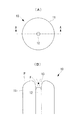
図1に示すように、ガイドワイヤ10は、ワイヤ11、光照射部としての光ファイバ12及び光源部(図示せず)とを備えている。
(First embodiment)
The guide wire according to the first embodiment of the present invention will be described below with reference to the drawings. The guide wire in this embodiment is used for pericardial puncture, and is configured as follows.
As shown in FIG. 1, the
ワイヤ11は、可撓性を有すると共に中空部を有し、先端面の長手方向の断面形状において、図1(B)に示すように、中空部を中心に左右対称であり、夫々がなだらかな凸形状になっている。
光源部は、ワイヤ11の基端側に設けられ、処置対象組織である心膜Pを脆弱化させるための所定の光(以下、単に「光」という)を光ファイバ12の入射端に向けて出射する。なお、光源としては、Nd:YAGレーザ(1064nm)を適用することができる。この他、SHG Nd:YAGレーザ(532nm),ArFエキシマーレーザ(193nm)、半導体レーザ(808nm,915nmなど)等を適用することもできる。
The
The light source unit is provided on the proximal end side of the
光ファイバ12は、入射端がワイヤ11の基端側に配置され、出射端がワイヤ11の先端よりも、例えば8mm程度ワイヤの基端側に配置されるようにワイヤの中空部に収容されている(図1(B)参照)。従って、ガイドワイヤ10の先端面には、ワイヤ11の先端面と光ファイバ12とによって凹部13が形成される。また、光ファイバ12の出射端から出射された光の焦点Fが、ワイヤの先端よりもワイヤの基端側に位置するようになっている。光ファイバ12は、ワイヤの基端側から先端側に向かって光を導光し、出射端から心膜に対して光を照射する。
The
なお、光ファイバ12の出射端の配置位置は、処置対象組織に応じて適宜決定することができる。本実施形態においては、光ファイバ12の出射端がワイヤの先端よりも、例えば8mm程度ワイヤの基端側に配置されていることとした。これは、処置対象組織が心膜である場合には、心筋の厚みが8〜11mmであるので、心筋への損傷を防止するために定めている。
In addition, the arrangement position of the emission end of the
以下、このように構成されたガイドワイヤ10により心膜穿刺を行う場合の作用について説明する。
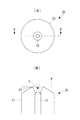
ガイドワイヤ10の先端を心膜付近の所望の位置まで挿入し(図2(A))、ガイドワイヤ10の先端を心膜Pの穿孔すべき部位に押し当てると、当該部位がガイドワイヤ10先端に形成された凹部13に入り込み、入り込んだ部位が焦点Fに到達する(図2(B))。そして、光源部から出射した光が光ファイバ12により導光され、光ファイバ12から出射した光が心膜のうち焦点Fに到達している部位に照射され、光が照射された部位が熱変性を起こして脆弱化する。このとき、当該部位には凸面となっているワイヤ11先端面により力が加えられているので、この力によって脆弱化した部位がわずかに穿孔し、ワイヤ11によって更に力を加えることにより、穿孔された部位が拡大しワイヤ11の外径と同程度の貫通孔を設けることができる。
Hereinafter, an operation when pericardial puncture is performed with the
When the distal end of the
以上述べたように、本実施形態によれば、凹部に入り込んで焦点Fに位置した心膜のみが脆弱化されて穿孔を可能とする一方、この凹部13により心膜は勿論、心膜近傍に位置する心臓の組織が過度にガイドワイヤ10の中空部に入り込むことがなく、心臓に対する損傷を防止することができる。煩雑な手順を経ることなく、ガイドワイヤのみによって容易に処置対象組織である心膜に対して貫通孔を設けることができる。すなわち、簡便な操作により容易に心膜を穿孔することができる。
As described above, according to the present embodiment, only the pericardium that enters the recess and is located at the focal point F is weakened to enable perforation, while the
続いて、上述した第1の実施形態に係るガイドワイヤ10の変形例について、図面を参照して説明する。
Subsequently, a modification of the
(変形例1)
変形例1に係るガイドワイヤ20は、ワイヤ21の先端面の形状が上記した第1の実施形態と異なっている(図3参照)。すなわち、ワイヤ21の先端面には、長手方向の断面において先鋭部22を備える形状となっている。このようにすることで、ワイヤ21の製造工程を簡便にすることができる。
(Modification 1)
The
(変形例2)
変形例2に係るガイドワイヤ30は、ワイヤ31の先端面が全体として斜面となっており、その長手方向断面において左右非対称の形状となっている(図4参照)。つまり、ワイヤ31は長手方向の断面において図4中左側に位置するワイヤ31Bが比較的短く、図4中右側に位置するワイヤ31Aが比較的長くなっている。また、長手方向の断面においてワイヤ31Aの先端部は先鋭となっており、ワイヤ31Bの先端はなだらかな凸形状となっている。
(Modification 2)
In the
このように構成されたガイドワイヤ30により心膜穿刺を行う場合は、以下のように行う。
ガイドワイヤ30の先端を心膜付近の所望の位置まで挿入し(図4(A))、ガイドワイヤ30の先端を心膜Pの穿孔すべき部位に押し当てると、当該部位がワイヤ31Aの先鋭な先端部に引っかかる。これにより穿孔すべき心膜の位置決めがなされる(図4(B))。この位置決めされた状態で、さらにガイドワイヤ30の先端を心膜Pの穿孔すべき部位に押し当てると、先端に形成された凹部13に入り込み、入り込んだ部位が焦点Fに到達する(図4(B))。
When pericardial puncture is performed using the
When the distal end of the
そして、光源部から出射した光が光ファイバ12により導光され、光ファイバ12から出射した光が心膜のうち焦点Fに到達している部位に照射され、光が照射された部位が熱変性を起こして脆弱化する。このとき、当該部位には凸面となっているワイヤ31先端面により力が加えられているので、この力によって脆弱化した部位がわずかに穿孔し、ワイヤ31によって更に力を加えることにより、穿孔された部位が拡大しワイヤ31の外径と同程度の貫通孔を設けることができる。
Then, the light emitted from the light source unit is guided by the
ワイヤ31Aに先鋭部が設けられていることから、例えば、心膜に対して斜めにガイドワイヤを挿入した場合等に、挿入に必要な力を低減できる。また、先鋭部によって穿孔すべき心膜に対して位置決めがなされるので、ガイドワイヤが滑って穿孔位置がずれることがない。
Since the
(第2の実施形態)
続いて、本発明の第2の実施形態に係るガイドワイヤについて図面を参照して説明する。
図5に示すように、ガイドワイヤ40は、ワイヤ41と、光照射部を構成するCO2レーザ光源42、レンズ43及び光学窓44と、を備えている。ガイドワイヤ40には穿刺針55が着脱可能となっている。
(Second Embodiment)
Subsequently, a guide wire according to a second embodiment of the present invention will be described with reference to the drawings.
As shown in FIG. 5, the
ワイヤ41は、中空の螺旋状のコイルワイヤであり可撓性を有している。ワイヤ41の内周面には、Siコーティングが施されており、後述するCO2レーザ光源42から出射した光を効率よく反射することができるようになっている。ワイヤ41先端部近傍には、ガイドワイヤ40に対して着脱可能な穿刺針55を固定するための凹部46が設けられている。なお、穿刺針55には、この凹部46に嵌合する凸部56が設けられている。
The
CO2レーザ光源42は、ワイヤ41の基端側に手元部48を介して設けられ、処置対象組織である心膜を脆弱化することが可能な、例えば、10.6μmの光を高出力でワイヤ41の中空部に向けて射出する。
レンズ43は、ZnSeレンズであり、ワイヤ41の基端側に配置された手元部48に設けられ、CO2レーザ光源42の射出端近傍に位置するようになっている。レンズ43は、CO2レーザ光源42から射出された光を効率よく透過するようになっている。
The CO2
The
光学窓44は、ワイヤ41の先端よりもやや基端側に設けられ、CO2レーザ光源42から射出されワイヤ41の中空部を導光された光を透過し、心膜に対する光の射出端となる。なお、光学窓44は、ワイヤ41の先端よりもやや基端側に設けられることから、ワイヤ41の先端とワイヤ41の中空部と光学窓44とで凹部45を形成する。この凹部45は、上述した第1の実施形態における凹部13と同様に、心膜が必要以上にガイドワイヤ40の中空部に入り込むことを防止することができる。
The
手元部48は、ワイヤ41とCO2レーザ光源42とを接続するものであり、手元部48のカプラーによって上述のようにレンズ43を固定している。すなわち、手元部48は、ワイヤ41とCO2レーザ光源42とをカプラー51を介して接続しており、ワイヤ41の基端部の雌ネジ49とカプラー51のリングネジ50とで固定している。従って、雌ネジ49とリングネジ50とを取り外すことにより、穿刺針55の着脱が可能となる。
The
このように構成されたガイドワイヤ40により心膜穿刺を行う場合の作用について説明する。
ガイドワイヤ40の先端を心膜付近の所望の位置まで挿入し、ガイドワイヤ40の先端を心膜の穿孔すべき部位に押し当てると、当該部位がガイドワイヤ40先端に形成された凹部45に入り込み、入り込んだ部位が光の焦点Fに到達する。
The operation when pericardial puncture is performed with the
When the distal end of the
そして、CO2レーザ光源42から出射した光がワイヤ41の中空部を介して導光され、光学窓44から出射される。これにより、光が照射された部位が熱変性を起こして脆弱化し、当該部位には凸面となっているワイヤ41先端面により力が加えられているので、この力によって脆弱化した部位がわずかに穿孔し、ワイヤ41によって更に力を加えることにより、穿孔された部位が拡大しワイヤ41の外径と同程度の貫通孔を設けることができる。すなわち、簡便な操作により容易に心膜を穿孔することができる。
The light emitted from the CO 2
(変形例)
上記した本発明の第2の実施形態の変形例に係るガイドワイヤ60について図6を参照して説明する。図6中、上記した第2の実施形態と同一の構成には同符号を付し、その説明を省略する。
図6に示すように、本変形例における光照射部は、ワイヤ41の先端よりもやや基端側に配置されたレンズ62と、該レンズ62よりも基端側に配置された半導体レーザ光源61とで構成されている。
このように構成することで、光源からガイドワイヤ先端までの構成要素を少なくすることができるため、光の減衰を抑制することができる。
(Modification)
A
As shown in FIG. 6, the light irradiating unit in the present modification includes a
By comprising in this way, since the component from a light source to a guide wire front-end | tip can be decreased, attenuation | damping of light can be suppressed.
(第3の実施形態)
上述した全ての実施形態に係るガイドワイヤは、その先端部の所定箇所に曲がりくせをつけることができる。この場合には、ガイドワイヤ先端から出射する光の出射方向を制御することができる。
(Third embodiment)
The guide wires according to all the embodiments described above can be bent at a predetermined portion of the distal end portion. In this case, the emission direction of the light emitted from the tip of the guide wire can be controlled.
例えば、図7に示すように、ガイドワイヤ70の先端部の所定箇所に略90度の曲がりくせ部68がつけられており、曲がりくせ部68よりも基端側に所定間隔をあけて穿刺針55の凹部と嵌合する凸部75が2箇所に設けられている。
ガイドワイヤ70は、穿刺針55が着脱された状態では穿刺針55によって矯正されて直線状になる一方で、ガイドワイヤ70単体では曲がりくせ部68において略90度に屈折した状態となっている。
For example, as shown in FIG. 7, a
The
このように構成されたガイドワイヤ70において心膜穿刺を行う場合は、以下のように行う。
すなわち、図8に示すように、ガイドワイヤ70に穿刺針55を取り付け、ガイドワイヤ70を直線状とした状態で心膜付近まで穿刺する。このとき、ガイドワイヤ70先端側の凸部75が穿刺針55の凹部58と嵌合しているので、穿刺針55を固定し、ガイドワイヤ70を押すことでガイドワイヤ70と穿刺針55との嵌合を解除し、ガイドワイヤ70を心膜側に移動させる。
When pericardial puncture is performed with the
That is, as shown in FIG. 8, the
この状態で、光を照射することにより脆弱化した部位をガイドワイヤ70先端部で押し広げることにより、心膜にガイドワイヤ70を貫通させる。ガイドワイヤ70の曲がりぐせ部68が穿刺針55先端を通過する直前で、ガイドワイヤ70の2箇所の凸部75のうち、手元側の凸部75と穿刺針55内側の凹部58が嵌合する。
In this state, the
曲がりぐせ部68が穿刺針55最先端よりも先端側に突出すると、ガイドワイヤ70の先端部が曲がりくせ部68に沿って曲がる。これによりガイドワイヤ70の先端の向きが変化、すなわち、光の射出方向が変化するので、ガイドワイヤ70の挿入方向の組織に光が照射されることはなく、当該組織が光によって脆弱化することがない。
When the
曲がりぐせ部68を、ガイドワイヤ70最先端から例えば、8mm以内としている場合には、心筋の厚みよりも小さいため、心筋を穿孔する虞がない。つまり、ガイドワイヤ70の曲がりくせ部によって光ファイバも共に曲がるので、光ファイバの先端への光の伝達効率が低下し、先端から射出される光量が低下する。これにより、心臓表面に与えるダメージを低減することもできる。更にガイドワイヤを押し込む事により、ガイドワイヤを心膜に貫通させる。
When the
なお、曲がりくせ部68の角度は任意であり、例えば、図9及び図10に示すガイドワイヤ71のように90度以下の角度とすることもできる。ガイドワイヤの曲がりくせ部68の角度を何れの角度とするかは、穿孔する部位に応じて定めることができる。
In addition, the angle of the bending
10,20,30,40,60,70,71 ガイドワイヤ
11,21,31,41 ワイヤ
12 光ファイバ
13,45 凹部
42 CO2レーザ光源
68 曲がりくせ部
10, 20, 30, 40, 60, 70, 71
Claims (3)
前記中空部を介して前記ワイヤの基端側から先端側に向かって処置対象組織を脆弱化させる光を導光し、該光を処置対象組織に照射する光照射部と、を備え、
該光照射部による光の出射端が前記ワイヤの先端よりも前記ワイヤの基端側に配置され、
前記光照射部によって出射された光の焦点位置が、前記ワイヤの先端よりも前記ワイヤの基端側に位置するガイドワイヤ。 A wire having flexibility and a hollow portion;
A light irradiation unit that guides light that weakens the treatment target tissue from the proximal end side to the distal end side of the wire through the hollow portion, and irradiates the treatment target tissue with the light, and
The light emitting end by the light irradiating part is disposed closer to the proximal end side of the wire than the distal end of the wire ,
A guide wire in which the focal position of the light emitted by the light irradiation unit is located closer to the proximal end side of the wire than the distal end of the wire.
前記ワイヤの外周部に突起が設けられ、
前記穿刺針の内周面に前記突起と嵌合する凹部が形成され、
該穿刺針の内側に前記ワイヤが挿通された際に、前記突起と前記凹部とが嵌合する請求項1又は請求項2に記載のガイドワイヤ。 A hollow puncture needle through which the wire can be inserted,
Protrusions are provided on the outer periphery of the wire,
A recess is formed on the inner peripheral surface of the puncture needle to be fitted with the protrusion,
The guide wire according to claim 1 or 2 , wherein when the wire is inserted inside the puncture needle, the protrusion and the recess are fitted.
Priority Applications (1)
| Application Number | Priority Date | Filing Date | Title |
|---|---|---|---|
| JP2012242530A JP6000806B2 (en) | 2012-11-02 | 2012-11-02 | Guide wire |
Applications Claiming Priority (1)
| Application Number | Priority Date | Filing Date | Title |
|---|---|---|---|
| JP2012242530A JP6000806B2 (en) | 2012-11-02 | 2012-11-02 | Guide wire |
Publications (2)
| Publication Number | Publication Date |
|---|---|
| JP2014090845A JP2014090845A (en) | 2014-05-19 |
| JP6000806B2 true JP6000806B2 (en) | 2016-10-05 |
Family
ID=50935380
Family Applications (1)
| Application Number | Title | Priority Date | Filing Date |
|---|---|---|---|
| JP2012242530A Expired - Fee Related JP6000806B2 (en) | 2012-11-02 | 2012-11-02 | Guide wire |
Country Status (1)
| Country | Link |
|---|---|
| JP (1) | JP6000806B2 (en) |
Families Citing this family (1)
| Publication number | Priority date | Publication date | Assignee | Title |
|---|---|---|---|---|
| CN110381896B (en) * | 2017-03-31 | 2022-09-13 | 日本瑞翁株式会社 | Support transfer device |
Family Cites Families (9)
| Publication number | Priority date | Publication date | Assignee | Title |
|---|---|---|---|---|
| FI861209A (en) * | 1985-03-22 | 1986-09-23 | Massachusetts Inst Technology | CATHETER FOR LASER UTFOERBAR BLODKAERLSKIRURGI. |
| JPS625341A (en) * | 1985-07-02 | 1987-01-12 | オリンパス光学工業株式会社 | Laser probe |
| EP0355996A3 (en) * | 1988-07-21 | 1990-05-02 | Advanced Interventional Systems, Inc. | Guidance and delivery system for high-energy pulsed laser light and endoscope |
| US5009655A (en) * | 1989-05-24 | 1991-04-23 | C. R. Bard, Inc. | Hot tip device with optical diagnostic capability |
| JPH0412743A (en) * | 1990-05-02 | 1992-01-17 | Olympus Optical Co Ltd | Laser probe |
| ATE182273T1 (en) * | 1992-08-18 | 1999-08-15 | Spectranetics Corp | GUIDE WIRE WITH FIBER OPTICS |
| US6200303B1 (en) * | 1997-04-30 | 2001-03-13 | Beth Israel Deaconess Medical Center, Inc. | Method and kit for transvenously accessing the pericardial space via the right atrium |
| US20070255303A1 (en) * | 2006-05-01 | 2007-11-01 | Ethicon Endo-Surgery, Inc. | Integrated Guidewire Needle Knife Device |
| JP2013202120A (en) * | 2012-03-27 | 2013-10-07 | Asahi Intecc Co Ltd | Guidewire |
-
2012
- 2012-11-02 JP JP2012242530A patent/JP6000806B2/en not_active Expired - Fee Related
Also Published As
| Publication number | Publication date |
|---|---|
| JP2014090845A (en) | 2014-05-19 |
Similar Documents
| Publication | Publication Date | Title |
|---|---|---|
| JP5257987B2 (en) | How to modify a surgical fiber | |
| JP6543628B2 (en) | Treatment device | |
| US9610125B2 (en) | Laser system and method for the treatment of body tissue | |
| EP2502103B1 (en) | Apparatus and method related to a distal end portion of an optical fiber having a substantially spherical shape | |
| US8790333B2 (en) | Skull cutting device | |
| JP2017000496A (en) | Needle processing method, laser beam processing machine, and needle | |
| JP2005168699A (en) | High frequency snare for endoscope | |
| CN110099648A (en) | Medical laser device and associated method | |
| JP6219518B2 (en) | Optical fiber cable, method for manufacturing the same, and light source module including the same | |
| JP6000806B2 (en) | Guide wire | |
| JP2005055811A (en) | Optical member, optical apparatus having the optical member incorporated therein, and method of assembling the optical apparatus | |
| WO2013047261A1 (en) | Abrasion device | |
| JP2016067527A (en) | Irradiation apparatus | |
| JP2000024001A (en) | Laser probe | |
| KR101451975B1 (en) | Apparatus for irradiating Laser and Method for irradiating Laser | |
| US20200093641A1 (en) | Surgical instrument, surgical device, and electronic control device | |
| JP6435668B2 (en) | Optical probe | |
| JP6419363B1 (en) | Treatment device | |
| JP5517828B2 (en) | Hollow waveguide and laser therapy device | |
| JP6333909B2 (en) | catheter | |
| JP5253045B2 (en) | Eyeless needle | |
| JP7336119B1 (en) | Light irradiation device and light irradiation system | |
| KR102582221B1 (en) | Chopper Needle for Cataract Surgery, Method for Manufacturing the Chopper Needle and Chopper for Cataract Surguery Comprising the Same Chopper Needle | |
| JP3180074U (en) | Laser fiber for PLDD | |
| JP6350043B2 (en) | Optical probe |
Legal Events
| Date | Code | Title | Description |
|---|---|---|---|
| A621 | Written request for application examination |
Free format text: JAPANESE INTERMEDIATE CODE: A621 Effective date: 20150806 |
|
| A977 | Report on retrieval |
Free format text: JAPANESE INTERMEDIATE CODE: A971007 Effective date: 20160617 |
|
| A131 | Notification of reasons for refusal |
Free format text: JAPANESE INTERMEDIATE CODE: A131 Effective date: 20160621 |
|
| A521 | Written amendment |
Free format text: JAPANESE INTERMEDIATE CODE: A523 Effective date: 20160714 |
|
| TRDD | Decision of grant or rejection written | ||
| A01 | Written decision to grant a patent or to grant a registration (utility model) |
Free format text: JAPANESE INTERMEDIATE CODE: A01 Effective date: 20160809 |
|
| A61 | First payment of annual fees (during grant procedure) |
Free format text: JAPANESE INTERMEDIATE CODE: A61 Effective date: 20160831 |
|
| R151 | Written notification of patent or utility model registration |
Ref document number: 6000806 Country of ref document: JP Free format text: JAPANESE INTERMEDIATE CODE: R151 |
|
| LAPS | Cancellation because of no payment of annual fees |