JP6000544B2 - Cancellation of magnetic disturbance caused by fluoroscope - Google Patents
Cancellation of magnetic disturbance caused by fluoroscope Download PDFInfo
- Publication number
- JP6000544B2 JP6000544B2 JP2011279383A JP2011279383A JP6000544B2 JP 6000544 B2 JP6000544 B2 JP 6000544B2 JP 2011279383 A JP2011279383 A JP 2011279383A JP 2011279383 A JP2011279383 A JP 2011279383A JP 6000544 B2 JP6000544 B2 JP 6000544B2
- Authority
- JP
- Japan
- Prior art keywords
- magnetic field
- fluoroscope
- reaction
- orientation
- magnetic
- Prior art date
- Legal status (The legal status is an assumption and is not a legal conclusion. Google has not performed a legal analysis and makes no representation as to the accuracy of the status listed.)
- Active
Links
- 238000006243 chemical reaction Methods 0.000 claims description 84
- 230000003094 perturbing effect Effects 0.000 claims description 61
- 239000011159 matrix material Substances 0.000 claims description 36
- 239000000523 sample Substances 0.000 claims description 35
- 230000004044 response Effects 0.000 claims description 14
- 238000003384 imaging method Methods 0.000 claims description 12
- 238000012546 transfer Methods 0.000 claims description 12
- 239000002184 metal Substances 0.000 claims description 4
- 238000000034 method Methods 0.000 description 64
- 238000005259 measurement Methods 0.000 description 14
- 230000006870 function Effects 0.000 description 8
- 230000005405 multipole Effects 0.000 description 8
- 239000013598 vector Substances 0.000 description 8
- 230000008569 process Effects 0.000 description 6
- 238000010586 diagram Methods 0.000 description 5
- 238000004458 analytical method Methods 0.000 description 4
- 238000012512 characterization method Methods 0.000 description 3
- 238000012937 correction Methods 0.000 description 3
- 238000013507 mapping Methods 0.000 description 3
- 230000003287 optical effect Effects 0.000 description 3
- 238000005457 optimization Methods 0.000 description 3
- 230000006978 adaptation Effects 0.000 description 2
- 230000003044 adaptive effect Effects 0.000 description 2
- 230000006399 behavior Effects 0.000 description 2
- 238000006073 displacement reaction Methods 0.000 description 2
- 230000005672 electromagnetic field Effects 0.000 description 2
- 125000001153 fluoro group Chemical group F* 0.000 description 2
- 238000009434 installation Methods 0.000 description 2
- 238000012986 modification Methods 0.000 description 2
- 230000004048 modification Effects 0.000 description 2
- 229930091051 Arenine Natural products 0.000 description 1
- 230000004075 alteration Effects 0.000 description 1
- 230000005540 biological transmission Effects 0.000 description 1
- 210000005242 cardiac chamber Anatomy 0.000 description 1
- 238000013500 data storage Methods 0.000 description 1
- 238000000354 decomposition reaction Methods 0.000 description 1
- 230000007423 decrease Effects 0.000 description 1
- 238000011161 development Methods 0.000 description 1
- 238000002059 diagnostic imaging Methods 0.000 description 1
- 239000003814 drug Substances 0.000 description 1
- 229940079593 drug Drugs 0.000 description 1
- 230000000694 effects Effects 0.000 description 1
- 238000011156 evaluation Methods 0.000 description 1
- 239000007943 implant Substances 0.000 description 1
- 238000004519 manufacturing process Methods 0.000 description 1
- 210000000056 organ Anatomy 0.000 description 1
- 239000002985 plastic film Substances 0.000 description 1
- 238000012545 processing Methods 0.000 description 1
- 230000009467 reduction Effects 0.000 description 1
- 239000007787 solid Substances 0.000 description 1
- 230000017105 transposition Effects 0.000 description 1
- 230000000007 visual effect Effects 0.000 description 1
Images


Classifications
-
- A—HUMAN NECESSITIES
- A61—MEDICAL OR VETERINARY SCIENCE; HYGIENE
- A61B—DIAGNOSIS; SURGERY; IDENTIFICATION
- A61B5/00—Measuring for diagnostic purposes; Identification of persons
- A61B5/06—Devices, other than using radiation, for detecting or locating foreign bodies ; determining position of probes within or on the body of the patient
- A61B5/061—Determining position of a probe within the body employing means separate from the probe, e.g. sensing internal probe position employing impedance electrodes on the surface of the body
- A61B5/062—Determining position of a probe within the body employing means separate from the probe, e.g. sensing internal probe position employing impedance electrodes on the surface of the body using magnetic field
-
- A—HUMAN NECESSITIES
- A61—MEDICAL OR VETERINARY SCIENCE; HYGIENE
- A61B—DIAGNOSIS; SURGERY; IDENTIFICATION
- A61B5/00—Measuring for diagnostic purposes; Identification of persons
- A61B5/72—Signal processing specially adapted for physiological signals or for diagnostic purposes
- A61B5/7203—Signal processing specially adapted for physiological signals or for diagnostic purposes for noise prevention, reduction or removal
-
- A—HUMAN NECESSITIES
- A61—MEDICAL OR VETERINARY SCIENCE; HYGIENE
- A61B—DIAGNOSIS; SURGERY; IDENTIFICATION
- A61B34/00—Computer-aided surgery; Manipulators or robots specially adapted for use in surgery
- A61B34/20—Surgical navigation systems; Devices for tracking or guiding surgical instruments, e.g. for frameless stereotaxis
-
- A—HUMAN NECESSITIES
- A61—MEDICAL OR VETERINARY SCIENCE; HYGIENE
- A61B—DIAGNOSIS; SURGERY; IDENTIFICATION
- A61B5/00—Measuring for diagnostic purposes; Identification of persons
- A61B5/72—Signal processing specially adapted for physiological signals or for diagnostic purposes
- A61B5/7203—Signal processing specially adapted for physiological signals or for diagnostic purposes for noise prevention, reduction or removal
- A61B5/7217—Signal processing specially adapted for physiological signals or for diagnostic purposes for noise prevention, reduction or removal of noise originating from a therapeutic or surgical apparatus, e.g. from a pacemaker
-
- A—HUMAN NECESSITIES
- A61—MEDICAL OR VETERINARY SCIENCE; HYGIENE
- A61B—DIAGNOSIS; SURGERY; IDENTIFICATION
- A61B6/00—Apparatus for radiation diagnosis, e.g. combined with radiation therapy equipment
- A61B6/58—Testing, adjusting or calibrating apparatus or devices for radiation diagnosis
- A61B6/582—Calibration
- A61B6/585—Calibration of detector units
-
- A—HUMAN NECESSITIES
- A61—MEDICAL OR VETERINARY SCIENCE; HYGIENE
- A61B—DIAGNOSIS; SURGERY; IDENTIFICATION
- A61B6/00—Apparatus for radiation diagnosis, e.g. combined with radiation therapy equipment
- A61B6/58—Testing, adjusting or calibrating apparatus or devices for radiation diagnosis
- A61B6/587—Alignment of source unit to detector unit
-
- A—HUMAN NECESSITIES
- A61—MEDICAL OR VETERINARY SCIENCE; HYGIENE
- A61B—DIAGNOSIS; SURGERY; IDENTIFICATION
- A61B17/00—Surgical instruments, devices or methods, e.g. tourniquets
- A61B2017/00681—Aspects not otherwise provided for
- A61B2017/00725—Calibration or performance testing
-
- A—HUMAN NECESSITIES
- A61—MEDICAL OR VETERINARY SCIENCE; HYGIENE
- A61B—DIAGNOSIS; SURGERY; IDENTIFICATION
- A61B34/00—Computer-aided surgery; Manipulators or robots specially adapted for use in surgery
- A61B34/20—Surgical navigation systems; Devices for tracking or guiding surgical instruments, e.g. for frameless stereotaxis
- A61B2034/2046—Tracking techniques
- A61B2034/2051—Electromagnetic tracking systems
-
- A—HUMAN NECESSITIES
- A61—MEDICAL OR VETERINARY SCIENCE; HYGIENE
- A61B—DIAGNOSIS; SURGERY; IDENTIFICATION
- A61B34/00—Computer-aided surgery; Manipulators or robots specially adapted for use in surgery
- A61B34/20—Surgical navigation systems; Devices for tracking or guiding surgical instruments, e.g. for frameless stereotaxis
- A61B2034/2046—Tracking techniques
- A61B2034/2055—Optical tracking systems
-
- A—HUMAN NECESSITIES
- A61—MEDICAL OR VETERINARY SCIENCE; HYGIENE
- A61B—DIAGNOSIS; SURGERY; IDENTIFICATION
- A61B90/00—Instruments, implements or accessories specially adapted for surgery or diagnosis and not covered by any of the groups A61B1/00 - A61B50/00, e.g. for luxation treatment or for protecting wound edges
- A61B90/36—Image-producing devices or illumination devices not otherwise provided for
- A61B90/37—Surgical systems with images on a monitor during operation
- A61B2090/376—Surgical systems with images on a monitor during operation using X-rays, e.g. fluoroscopy
-
- A—HUMAN NECESSITIES
- A61—MEDICAL OR VETERINARY SCIENCE; HYGIENE
- A61B—DIAGNOSIS; SURGERY; IDENTIFICATION
- A61B2560/00—Constructional details of operational features of apparatus; Accessories for medical measuring apparatus
- A61B2560/02—Operational features
- A61B2560/0223—Operational features of calibration, e.g. protocols for calibrating sensors
-
- A—HUMAN NECESSITIES
- A61—MEDICAL OR VETERINARY SCIENCE; HYGIENE
- A61B—DIAGNOSIS; SURGERY; IDENTIFICATION
- A61B6/00—Apparatus for radiation diagnosis, e.g. combined with radiation therapy equipment
- A61B6/12—Devices for detecting or locating foreign bodies
-
- A—HUMAN NECESSITIES
- A61—MEDICAL OR VETERINARY SCIENCE; HYGIENE
- A61B—DIAGNOSIS; SURGERY; IDENTIFICATION
- A61B6/00—Apparatus for radiation diagnosis, e.g. combined with radiation therapy equipment
- A61B6/44—Constructional features of apparatus for radiation diagnosis
- A61B6/4429—Constructional features of apparatus for radiation diagnosis related to the mounting of source units and detector units
- A61B6/4435—Constructional features of apparatus for radiation diagnosis related to the mounting of source units and detector units the source unit and the detector unit being coupled by a rigid structure
- A61B6/4441—Constructional features of apparatus for radiation diagnosis related to the mounting of source units and detector units the source unit and the detector unit being coupled by a rigid structure the rigid structure being a C-arm or U-arm
-
- A—HUMAN NECESSITIES
- A61—MEDICAL OR VETERINARY SCIENCE; HYGIENE
- A61B—DIAGNOSIS; SURGERY; IDENTIFICATION
- A61B6/00—Apparatus for radiation diagnosis, e.g. combined with radiation therapy equipment
- A61B6/48—Diagnostic techniques
- A61B6/486—Diagnostic techniques involving generating temporal series of image data
- A61B6/487—Diagnostic techniques involving generating temporal series of image data involving fluoroscopy
Description
本発明は概して、生体内に配置された物体の位置の感知に関し、特にその位置のセンサに影響を及ぼす磁気擾乱の相殺に関する。 The present invention relates generally to sensing the position of an object placed in a living body, and more particularly to canceling magnetic disturbances that affect the sensor at that position.
様々な医療的手技に伴い、センサ、チューブ、カテーテル、投薬装置、及びインプラントなどの物体が体内に設置される。これらの処置中に、この物体及びその周辺を可視化において医師を支援するために、リアルタイム撮像方法がしばしば用いられる。いくつかの方法は、磁界を利用する物体を用いて物体を追跡する。しかし、磁界での擾乱が追跡において誤差を発生させる可能性がある。 With various medical procedures, objects such as sensors, tubes, catheters, medication devices, and implants are placed in the body. During these procedures, real-time imaging methods are often used to assist the physician in visualizing the object and its surroundings. Some methods track an object using an object that utilizes a magnetic field. However, disturbances in the magnetic field can cause errors in tracking.
開示を参照により本明細書に援用する、Holmesらの米国特許第6,714,008号は、大きな物体の磁界を決定するための磁気勾配測定方法論を記載している。 Holmes et al US Pat. No. 6,714,008, the disclosure of which is incorporated herein by reference, describes a magnetic gradient measurement methodology for determining the magnetic field of large objects.
開示を参照により本明細書に援用する、Bar Talらの米国特許出願第2004/0034515号は、電磁気系中の位置測定及び向き測定を推定するための方法を記載している。本方法は、測定のためのモデルと1つ又はそれ以上の測定値との間の差を最小化することを含む。 Bar Tal et al. US Patent Application No. 2004/0034515, the disclosure of which is incorporated herein by reference, describes a method for estimating position and orientation measurements in an electromagnetic system. The method includes minimizing a difference between a model for measurement and one or more measurements.
開示を参照により本明細書に援用する、SatiらのW.I.P.O特許公開第WO/2004/006770号は、医学用撮像システムを較正するための方法を記載している。本方法は、Cアーム撮像装置の複数の向きのそれぞれに関して、撮像源の位置及び該当する場合は磁界歪みを決定することが可能であることが述べられている。 Sati et al., W., the disclosure of which is incorporated herein by reference. I. P. O Patent Publication No. WO / 2004/006770 describes a method for calibrating a medical imaging system. The method is stated to be able to determine the position of the imaging source and, if applicable, the magnetic field distortion for each of a plurality of orientations of the C-arm imaging device.
開示を参照により本明細書に援用する、Andersonらの米国特許出願第2005/0107687号は、電磁気追跡装置における歪み低減のためのシステムを記載している。本システムの特定の実施形態は、計器の追跡挙動を解析するための追跡解析ユニット及び計器の追跡挙動を相殺するための追跡修正ユニットを含むことが述べられている。 Anderson et al., US Patent Application No. 2005/0107687, the disclosure of which is incorporated herein by reference, describes a system for distortion reduction in an electromagnetic tracking device. Certain embodiments of the system are stated to include a tracking analysis unit for analyzing the tracking behavior of the instrument and a tracking correction unit for canceling the tracking behavior of the instrument.
開示を参照によって本明細書に援用する、Andersonらの米国特許出願第2007/0055125号は、電磁界を発生させるよう配置された磁界発生器及び電磁界を検出するよう配置された磁界センサを含む電磁気追跡システムを記載している。 Anderson et al. US Patent Application No. 2007/0055125, the disclosure of which is incorporated herein by reference, includes a magnetic field generator arranged to generate an electromagnetic field and a magnetic field sensor arranged to detect the electromagnetic field. An electromagnetic tracking system is described.
開示を参照により本明細書に援用する、Chandonnetらの米国特許出願第2008/0183064号は、電磁(EM)界歪みを検出するための方法を記載している。本方法は、関心体積内のEM界の測定値を取得するよう関心体積内に配置されたセンサアセンブリをサンプリングすること、及び関心体積内のEM界歪みを検出するよう測定値を監視することとを含む。 Chandonnet et al., US Patent Application No. 2008/0183064, the disclosure of which is incorporated herein by reference, describes a method for detecting electromagnetic (EM) field distortion. The method samples a sensor assembly disposed within the volume of interest to obtain a measurement of the EM field within the volume of interest, and monitors the measurement to detect EM field distortion within the volume of interest; including.
開示を参照により本明細書に援用する、Osadchyらの米国特許第6,147,480号は、磁界に反応する物品の導入に起因する干渉の存在下、及び物体の付近にて、エネルギー場を用いて物体を追跡するための方法を記載している。 Osadchy et al., US Pat. No. 6,147,480, the disclosure of which is incorporated herein by reference, describes the energy field in the presence of interference due to the introduction of articles that react to magnetic fields and in the vicinity of objects. Describes a method for using to track an object.
開示を参照により本明細書に援用する、Hansenらの米国特許第5,767,669号は、固定された位置から発生したパルス磁界を用いるリモートセンサの位置及び向きを決定するためのシステムを記載している。渦電流歪みが、システムによって個別に感知され減算される。 Hansen et al., US Pat. No. 5,767,669, whose disclosure is incorporated herein by reference, describes a system for determining the position and orientation of a remote sensor using a pulsed magnetic field generated from a fixed position. doing. Eddy current distortion is sensed and subtracted separately by the system.
開示を参照により本明細書に援用する、Viswanathanの米国特許第7,657,075号は、三次元画像データとX線撮像システムとを位置合わせするための三次元術前画像データセットの変換を決定するための方法を記載している。 Viswanathan, US Pat. No. 7,657,075, the disclosure of which is incorporated herein by reference, provides for the conversion of a 3D pre-operative image data set to align 3D image data with an X-ray imaging system. Describes the method for determining.
開示を参照により本明細書に援用する、Boeseらの米国特許第7,689,019号は、物体の二次元投影画像を同一の物体の三次元画像データ記録に対して位置合わせするための方法及び装置を記載している。物体に含まれる三次元機能は、三次元画像中で識別可能でもあるが、記号を使って再現されている。 Boese et al., US Pat. No. 7,689,019, the disclosure of which is incorporated herein by reference, describes a method for aligning a two-dimensional projection image of an object with a three-dimensional image data record of the same object. And a device are described. The 3D function contained in the object is recognizable in the 3D image, but is reproduced using symbols.
開示を参照により本明細書に援用する、Mullickらの米国特許出願第2009/0010540号は、画像の位置合わせを実行するための方法を記載している。本方法は、参照画像データセット及びターゲット画像データセットを取得すること、並びに参照画像データセット中の対象領域に関する画像マスクを規定することを含む。 US Patent Application No. 2009/0010540 to Mullick et al., Whose disclosure is incorporated herein by reference, describes a method for performing image registration. The method includes obtaining a reference image data set and a target image data set, and defining an image mask for a region of interest in the reference image data set.
開示を参照により本明細書に援用する、Dekelの米国特許出願第2002/0172328号は、計器の空間座標をその対応するX線投影画像に変換するための方法を記載している。本方法は、較正ツールの空間座標及びX線投影画像を同時に記録することによって、X線ビーム撮像システムの座標系を位置装置と位置合わせすることに基づいていることが述べられている。 Dekel U.S. Patent Application No. 2002/0172328, the disclosure of which is incorporated herein by reference, describes a method for converting the spatial coordinates of an instrument into its corresponding X-ray projection image. It is stated that the method is based on aligning the coordinate system of the X-ray beam imaging system with the positioning device by simultaneously recording the spatial coordinates of the calibration tool and the X-ray projection image.
本発明の一実施形態は、
複数の磁気送信機を用いて、領域中に磁界を発生させることと、
磁界摂動要素を領域中に導入することと、
磁界摂動要素内の各磁気送信機の複数画像を特性評価することと、
特性評価された画像に基づいて、領域中で反応磁界を計算することと、
領域中にプローブを配置し、プローブにおける摂動した磁界を測定することと、
測定された摂動磁界及び計算した反応磁界に対応してプローブの位置を決定することと、
を含む方法を提供する。
One embodiment of the present invention
Using a plurality of magnetic transmitters to generate a magnetic field in the region;
Introducing a magnetic field perturbation element into the region;
Characterizing multiple images of each magnetic transmitter in a magnetic field perturbing element;
Calculating a reaction field in the region based on the characterized image;
Placing a probe in the region and measuring the perturbed magnetic field at the probe;
Determining the position of the probe in response to the measured perturbation field and the calculated reaction field;
A method comprising:
通常、磁界を発生させることは、磁界摂動要素が不在の磁界を測定することと、その領域中に存在する磁界摂動要素を伴う磁界を測定することと、を含む。 Generally, generating a magnetic field includes measuring a magnetic field that is free of magnetic field perturbing elements and measuring a magnetic field with magnetic field perturbing elements present in the region.
開示された一実施形態では、磁界摂動要素を領域中に導入することは、磁界摂動要素の位置及び向きを、磁気送信機によって規定された軸に対して測定することを含む。磁界摂動要素の位置及び向きを測定することは、反応磁界に対応して位置及び向きを適応的に計算することを含んでもよい。 In one disclosed embodiment, introducing a magnetic field perturbing element into the region includes measuring the position and orientation of the magnetic field perturbing element relative to an axis defined by the magnetic transmitter. Measuring the position and orientation of the magnetic field perturbing element may include adaptively calculating the position and orientation corresponding to the reaction magnetic field.
別の開示された実施形態では、複数の画像を特性評価することは、複数画像が互いに対して所定の構成にあると仮定することを含む。所定の形状は矩形を含んでもよく、複数の画像は矩形の角部及び中心に位置する5つの画像を含んでもよい。 In another disclosed embodiment, characterizing the plurality of images includes assuming that the plurality of images are in a predetermined configuration with respect to each other. The predetermined shape may include a rectangle, and the plurality of images may include five images located at the corners and the center of the rectangle.
更に別の実施形態では、反応磁界を計算することは、球面調和関数展開により、磁界を計算することを含む。反応磁界を計算することは、最大3次までの前記球面調和関数展開を実行することを含んでもよい。 In yet another embodiment, calculating the reaction magnetic field includes calculating the magnetic field by spherical harmonic expansion. Calculating the reaction magnetic field may include performing the spherical harmonic expansion up to a third order.
あるいは又はこれに加えて、球面調和関数展開により磁界を計算することは、展開を空間転送行列として設定することを含んでもよく、本方法は、磁界摂動要素の特性を反応磁界行列として決定することを更に含んでもよく、反応磁界を計算することは、空間転送行列と反応磁界行列との積に対応してもよい。 Alternatively or in addition, calculating the magnetic field by spherical harmonic expansion may include setting the expansion as a spatial transfer matrix, and the method determines the characteristics of the magnetic perturbing element as the reaction magnetic field matrix. And calculating the reaction magnetic field may correspond to a product of the spatial transfer matrix and the reaction magnetic field matrix.
典型的に、プローブを配置することは、患者の体内にプローブを配置することを含む。 Typically, placing the probe includes placing the probe in the patient's body.
一実施形態では、磁界摂動要素は、蛍光透視鏡の少なくとも1つのセクションを含む。本方法は、蛍光透視鏡の蛍光透視鏡軸を、送信機によって規定された軸に対して位置合わせすることを含んでもよい。蛍光透視鏡軸を位置合わせすることは、送信機に固定するよう接続されたカメラで、蛍光透視鏡に取り付けられた基準マークの画像を作成することを含んでもよい。磁界摂動要素を導入することは、画像に対応して磁界摂動要素の位置及び向きを測定することを含んでもよい。 In one embodiment, the magnetic field perturbing element includes at least one section of a fluoroscope. The method may include aligning the fluoroscope axis of the fluoroscope with respect to the axis defined by the transmitter. Aligning the fluoroscope axis may include creating an image of a fiducial mark attached to the fluoroscope with a camera connected to be secured to the transmitter. Introducing the magnetic field perturbing element may include measuring the position and orientation of the magnetic field perturbing element in response to the image.
本発明の一実施形態により、
領域中で磁界を発生するよう構成された複数の磁気送信機と、
領域中に導入された磁界摂動要素と、
プロセッサであって、磁界摂動要素内の各磁気送信機の複数の画像を特性評価し、
特性評価された画像に基づいて、領域中の反応磁界を計算し、
領域中に配置されたプローブにて摂動した磁界を測定し、
測定された摂動した磁界及び前記計算された反応磁界に対応して、プローブの位置を決定するよう構成される、プロセッサと、
を含む装置が更に提供される。
According to one embodiment of the present invention,
A plurality of magnetic transmitters configured to generate a magnetic field in the region;
A magnetic field perturbation element introduced into the region;
A processor for characterizing a plurality of images of each magnetic transmitter in a magnetic field perturbing element;
Based on the characterized image, calculate the reaction field in the region,
Measure the magnetic field perturbed by the probe placed in the area,
A processor configured to determine a position of the probe in response to a measured perturbed magnetic field and the calculated response magnetic field;
There is further provided an apparatus comprising:
本発明の一実施形態により、
位置パッド上に、患者に磁界を発生させるよう構成された磁気送信機を据え付けることと、
位置パッドにそれぞれの固定された向きで位置パッドカメラを取り付けることと、
位置パッドに回転可能なカメラを接続させることと、
患者を撮像するよう構成された蛍光透視鏡に、基準マークを取り付けることと、
蛍光透視鏡を、異なる位置に位置付けることと、
を含み、
各位置に関しては、
回転可能なカメラを既知の向きに配向させ、基準マークのそれぞれの画像を、回転可能なカメラ及び位置パッドカメラで作成することと、
位置パッドの軸に対して蛍光透視鏡の位置及び向きを位置合わせするよう、それぞれの画像を解析することと、
を含む方法が更に提供される。
According to one embodiment of the present invention,
Installing a magnetic transmitter on the position pad configured to generate a magnetic field in the patient;
Attaching the position pad camera to the position pad in each fixed orientation;
Connecting a rotatable camera to the position pad;
Attaching a reference mark to a fluoroscope configured to image a patient;
Positioning the fluoroscope in different positions;
Including
For each position,
Orienting a rotatable camera in a known orientation and creating an image of each of the fiducial marks with the rotatable camera and position pad camera;
Analyzing each image to align the position and orientation of the fluoroscope with respect to the axis of the position pad;
Is further provided.
本方法は、回転可能なカメラを位置パッドから取り外すことと、位置パッドカメラにより作成された基準マークの画像のみを用いて、位置パッドの軸に対して蛍光透視鏡の位置及び向きを決定することと、を含んでもよい。一実施形態では、位置パッドカメラを位置パッドに取り付けることは、取り外し可能なジグを位置パッドに取り付けることと、カメラでジグを撮像することによって、位置パッドカメラをそれぞれの固定された向きに整列させることと、を含む。 The method includes removing the rotatable camera from the position pad and determining the position and orientation of the fluoroscope relative to the position pad axis using only the fiducial mark image created by the position pad camera. And may be included. In one embodiment, attaching the position pad camera to the position pad aligns the position pad camera to each fixed orientation by attaching a removable jig to the position pad and imaging the jig with the camera. Including.
本発明の一実施形態により、
位置パッドと、
位置パッド上に据え付けられ、患者に磁界を発生させるよう構成された磁気送信機と、
それぞれの固定した向きで位置パッドに取り付けられた位置パッドカメラと、
位置パッドに接続された回転可能なカメラと、
患者を撮像するよう構成された蛍光透視鏡と、
蛍光透視鏡に取り付けられた基準マークと、
プロセッサであって、
異なる位置に蛍光透視鏡を位置付けるよう構成され、各位置に関しては、
回転可能なカメラを既知の向きに配向させ、回転可能なカメラ及び位置パッドカメラで基準マークのそれぞれの画像を作成するよう、並びに
位置パッドの軸に対して蛍光透視鏡の位置及び向きを位置合わせするよう、それぞれの画像を解析するよう構成されたプロセッサと、
を含む装置が更に提供される。
According to one embodiment of the present invention,
A position pad;
A magnetic transmitter mounted on the position pad and configured to generate a magnetic field in the patient;
A position pad camera attached to the position pad in each fixed orientation;
A rotatable camera connected to the position pad;
A fluoroscope configured to image a patient;
A reference mark attached to the fluoroscope;
A processor,
It is configured to position the fluoroscope at different positions, and for each position,
Orient the rotatable camera in a known orientation, create images of each of the fiducial marks with the rotatable camera and the position pad camera, and align the position and orientation of the fluoroscope with respect to the position pad axis A processor configured to analyze each image, and
There is further provided an apparatus comprising:
本開示は、以下のより詳細な実施形態の記述、及びその図面により、より完全に理解され得る。 The present disclosure can be more fully understood from the following more detailed description of the embodiments and the drawings thereof.
概論
本発明の実施形態は、領域中の磁界で発生した摂動の相殺のための方法を提供する。摂動は、典型的には金属成分である摂動要素を磁気送信機によって発生した磁界へ導入することによって起こる。摂動要素の存在を相殺するために、本発明の実施形態によって用いられる反応磁界モデルは、各磁気送信機が要素中で送信機の複数の画像を作成することを仮定する。モデルは、各画像がそれぞれの反応磁界を発生させて、それが送信機によって発生した磁界を全体で摂動させるよう作用することを仮定する。
Overview Embodiments of the present invention provide a method for canceling perturbations caused by magnetic fields in a region. Perturbations occur by introducing perturbation elements, typically metallic components, into a magnetic field generated by a magnetic transmitter. To offset the presence of perturbing elements, the reactive magnetic field model used by embodiments of the present invention assumes that each magnetic transmitter creates multiple images of the transmitter in the element. The model assumes that each image generates a respective reactive magnetic field that acts to perturb the magnetic field generated by the transmitter as a whole.
各画像は、通常は多極子、すなわち、双極子、四極子及び/又は高次極子などの組み合わせとして特性評価され得る。各画像の特性は、とりわけ画像を生じさせる送信機磁界にも依存する。モデルは、通常、磁界が球面調和関数展開によって表されることができることを想定することによって、また画像の総合特性に従って、多極子画像のそれぞれから反応磁界を計算する。典型的に、画像特性は、摂動要素不在中はもとより、摂動要素の存在下での送信機からの磁界を測定することによって効果的に決定され、またこの特性は、空間転送行列及び反応磁界行列の観点から表され得る。 Each image can typically be characterized as a combination of multipoles, ie, dipoles, quadrupoles and / or higher order poles. The characteristics of each image also depend on, among other things, the transmitter magnetic field that produces the image. The model usually calculates the reaction field from each of the multipole images by assuming that the field can be represented by a spherical harmonic expansion and according to the overall properties of the image. Typically, image characteristics are effectively determined by measuring the magnetic field from the transmitter in the presence of the perturbing element as well as in the absence of the perturbing element, and this characteristic is also determined by the spatial transfer matrix and the reaction field matrix. Can be expressed in terms of
一旦、画像が特性評価されたら、領域中に配置されたプローブが摂動磁界を測定する。次に、領域中のプローブの位置が、測定された磁界及び上述のように計算された反応磁界に対応して計算されてもよい。 Once the image has been characterized, a probe placed in the region measures the perturbed magnetic field. Next, the position of the probe in the region may be calculated corresponding to the measured magnetic field and the reaction magnetic field calculated as described above.
システムの説明
本発明の実施形態による、カテーテルプローブ22の遠位端21の位置を感知するよう構成された、位置感知システム20の概略描写図である図1、遠位端21を示す概略的詳細図である図2、及びシステム20で使用される要素の概略図である図3を参照する。通常、プローブ22は、システム20の操作段階中に医療専門家によって患者の体腔又は器官中に挿入され、システムの較正段階中には存在しない。明確化のために、図1では、プローブ22は破線で示されている。患者は、通常、位置感知システム20を操作することができる医療専門家によって実行される処置中に、手術台24上に横たわる。明確化及び簡略化のために、図1には患者及び医療専門家の双方共示されていない。
System Description FIG. 1, which is a schematic depiction of a
例えば、以下に記載のプローブ22は、患者の心臓の室内での侵襲的処置で使用されることが仮定される。患者は、概ね類似した交番磁界発信器コイル32A、32B、...の構成28を含む位置バッド26を患者の下に配置することによって発生する磁界中の手術台24上に配置される。コイルは、本明細書において総じて磁界発信器コイル32とも称される。コイル32は、これらの交番磁界を領域30中に発生させ、図1では楕円として概略的に図示される。図3は、コイル32の代表的な配列を図示している。
For example, it is assumed that the
典型的に、また図3に図示されるように、配列28は、3組の三軸コイル34、36、及び38として形成された送信機コイル32を含み、三軸コイルの各組は、互いに直交する3つのコイルを含む。しかしながら、配列28以外の磁気送信機コイル32の配列が可能であり、このような配列は、当該技術分野における当業者には明らかであろう。開示を参照により本明細書に援用する、Govariの米国特許第6,484,118号は、配列28に似たコイルの配列と同様に、システム20中に使用され得るコイル32の他の配列を記載している。
Typically, and as illustrated in FIG. 3, the
本明細書における記載は、遠位端21が、遠位端(この遠位端は、通常、図2に図示される電極48などの他の要素を含む)に設置される電磁(EM)センサ46の一部として、概ね直交する3つのコイル40、42、及び44を含むことを仮定している。コイル32によって発生した磁界は、コイルにより感知される磁界により、センサ46のコイル中で電気信号を生成する。センサ46のコイルからの電気信号は、プローブ22の位置の座標及び向きの座標を決定するよう信号を解析するコントロールユニット50に運ばれる。座標は、位置パッド26に対して固定された、図3に図示される直交する1組のxyz軸を基準にすると仮定される。
The description herein describes an electromagnetic (EM) sensor in which the
プローブ22の位置及び向きを検出するための遠位端21中のコイルの他の配列は、当該技術分野において既知である。1つのそのような配列は、磁界の投影を測定する1つのコイルを使用する。コイル40、42、及び44により例示されるものとは異なるコイル配列を説明するために、当該技術分野における当業者は、必要な変更を加えて本記載を適合させることが可能であろう。
Other arrangements of coils in the
コントロールユニット50は、典型的には適切な信号処理回路を備えたコンピュータであるプロセッサ52を含む。プロセッサは、システム20を操作するためのデータが記憶されている揮発性データ記憶装置及び非揮発性データ記憶装置の双方を通常含むメモリ54を使用する。プロセッサは、プローブ22の位置の視覚的ディスプレイ56を提供することが可能なコンソールを駆動するよう接続されている。
The
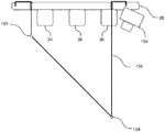
システム20は、蛍光透視鏡コントローラ61によって操作され、かつ手術台24上の患者の蛍光透視画像を作成することができる、蛍光透視鏡60を含む。蛍光透視鏡コントローラ61は、コントロールユニット50のサブユニットであると仮定される。蛍光透視鏡60は、本明細書ではコリメーター62とも称される視準されたX線源62及び検出器64を含む多数のセクションを有する。コリメーター及び検出器は、それらに横軸68及び軸68を通って紙面に垂直な軸の2つの軸の周りを回転させる別のセクションである「Cビーム」66によって、共に連結されている。Cビームは、コリメーター及び検出器を、横軸に平行な方向など、空間において移動させることも可能である。Cビーム66は、蛍光透視鏡の軸68周囲の回転の際に、互いに固定された配列に、及び互いから一定の距離にて、コリメーター及び検出器を保持する。典型的に、蛍光透視鏡60によって作成される画像は、軸68の周りの任意の向きに回転した蛍光透視鏡で作成されてもよく、その向きは、患者のニーズ及び専門的操作システム20の条件に応じて選択される。
The
通常、蛍光透視鏡60は、プローブ22が使用されるのとほぼ同時にその画像を作成するよう作動する。しかし、領域30に近接している蛍光透視鏡の金属成分は、その領域中でコイル32によって発生した磁界を改変させる。これらの改変に対する相殺なしでは、プローブ22の測定された位置における誤差が導入される。本明細書で記載されるように、本発明の実施形態は、手術台24に対する蛍光透視鏡60の向き又は位置に関係なく、蛍光透視鏡60によって生じる磁界における改変を相殺して、プローブ22の測定された位置における誤差が導入されるのを防ぐ。
Typically, the
典型的に、システム20は、単純化のために図には示されていないが、以下の説明で必要なものとして言及される、他の要素を含む。例えば、システム20は、1つ以上の体表面電極からの信号を受信するように接続されて、ECG同期信号をコントロールユニット50に供給する、心電図(ECG)モニターを含んでもよい。
The
図1の構成は、概念的明確化のためだけに選択された構成例である。代替的な実施形態では、他の任意の適切な構成を用いることもできる。典型的には、プロセッサ52は、本明細書に記載される機能を実行するようにソフトウェアでプログラムされる。ソフトウェアは、例えばネットワークを介して電子形式でプロセッサにダウンロードされてもよく、あるいは代替又は追加として、磁気、光学、若しくは電子メモリなどの非一時的な有形媒体に提供及び/又は保存されてもよい。
The configuration of FIG. 1 is an example configuration selected for conceptual clarity only. In alternate embodiments, any other suitable configuration may be used. Typically, the
システム20は、領域30内でコイル32によって発生した磁界をプロットすることが可能な装置も含む。本発明の一実施形態では、マッパー70が、磁界をプロットするために用いられ、マッパーは、プラスチックのシートなどの固体ベース上の既知の位置に固定するよう据え付けられた磁界検出器72の配列を含む。マッパー70は、位置パッド26に対して既知の所定の位置及び向きで手術台24上に配置できるように構成されている。一実施形態では、マッパー70は50個の検出器を含む。典型的に、検出器は、磁界及びすべてのその無視できない勾配が測定可能であるように、マッパー内に構成される。一代替実施形態では、マッパーは、高さ×幅×長さ=150mm×250mm×250mmの概算寸法を有する矩形状箱内に分配された78個の検出器を有する。
The
マッパーは、検出器72からの磁気測定を用いて、通常は左右部材に対して、並びに頭部材及び足部材に対してぼぼ中央に配置されてもよい。
The mapper may be placed roughly in the middle with respect to the left and right members and with respect to the head and foot members, typically using magnetic measurements from the
システム20の操作に関する次の説明では、マッパー70は磁界をプロットするために用いられることが想定されるが、マッパーは、領域30内の磁界を測定するための1つの代表的なシステムであることが理解され、既知の位置に移動させることが可能な1つ以上の磁界検出器などの他の適切なシステムが使用されてもよい。このような代替的磁界プロッティングシステムは、当該技術分野における当業者には明確となるであろうし、本発明の範囲内に含まれることが想定される。
In the following description of the operation of the
検出器72は、Hallプローブ又はセンサ46に概ね類似するセンサなどのような、磁界の大きさ及び方向を測定するための任意の好都合なセンサを含んでもよい。検出器からの読取りは、通常、ケーブル74によってコントロールユニット50に転送されるが、無線伝送装置のような他の任意の好都合な転送方法が用いられてもよい。
The
以下により詳細に説明されるように、マッパー70は、システム20の較正段階で用いられるので、マッパー及びその接続ケーブルは図1では破線で示されている。システム20がその操作段階にあるときには、マッパー及びそのケーブルは取り外される。
As described in more detail below, the mapper 70 is used in the calibration phase of the
いくつかの実施形態では、システム20は、センサ46と概ね類似する1つ以上の参照センサ76を含む。センサ76は、以下に述べるように、コントロールユニット50に信号を提供して、コントロールユニット50が蛍光透視鏡60の位置及び向きを決定することができるようにする。典型的に、センサ76は、手術台24に対して固定されており、手術台の下に都合よく位置付けられることができる。別の方法としては、参照センサ76は、蛍光透視鏡60に固定されてもよい。
In some embodiments, the
ここで、本発明の実施形態による、プローブ22の遠位端21の位置を決定するための手順のフローチャート100である図4を参照する。フローチャート100は、第1較正段階102、それに続く第2操作段階104を含む。以下のフローチャートの記載もまた、以下の「反応磁界モデル」の見出しのセクションの一部分に言及している。
Reference is now made to FIG. 4, which is a
較正段階の第1マッピング工程106では、コイル32によって発生した磁界を摂動させ得るすべての物体(本明細書では磁界摂動源又は磁界摂動要素と称する)が、領域30及びその近辺から取り除かれる。そのような物体は、蛍光透視鏡60を含む。マッパー70は、位置パッド26に対して所定の位置及び向きで手術台24上に配置され、送信機コイル26が起動する。コントロールユニット50は磁界検出器72を作動させて、領域30内の未摂動磁界をマッピングする。
In the
マッパー70が所定の位置のままである第2マッピング工程108では、蛍光透視鏡60は、領域30の近辺で、位置パッド軸に対して特定の位置及び向き(LO)に配置される。コントロールユニット50は、蛍光透視鏡コントローラ61を用いて特定のLOを決定してもよい。あるいは、参照センサを含む実施形態では、コントロールユニット50は、「適合蛍光透視鏡位置」と表題を付けたセクションで以下に記載されるように、LOを決定するようセンサからの信号を用いてもよい。蛍光透視鏡の既知のLOを決定するための更なる別の光学的方法が、図5、6A、6B、及び7を参照して以下に説明されている。
In the
以下に説明するように、蛍光透視鏡60は、2つの摂動要素:コリメーター62及び検出器64を有することが想定される。以下に記載する工程110での特性評価が有効であるために、異なるLOがそれらが2つのセットで選択される:コリメーター62が領域30から遠く離れており、そのため検出器64のみが摂動要素である第1セット、及び検出器64が領域30から遠く離れており、そのためコリメーター62のみが摂動要素である第2セット。
As described below, the
それぞれの既知のLOに関して、コントロールユニット50は、領域30内の摂動した磁界をマッピングするように、磁界検出器72を作動させる。
For each known LO,
多極子特性評価工程110では、コントロールユニットは、蛍光透視鏡60の各摂動要素によって生じる摂動が、それぞれの要素内の磁気画像源によって発生した反応磁界によるものであることが想定される。工程110で実施される解析は、「反応磁界モデル」と表題を付けたセクションで、以下により詳細に説明される。磁気源は、摂動要素内、すなわち、コリメーター62及び検出器64の2つの摂動要素内の送信機コイル32の画像であると考えてよい。もし蛍光透視鏡60が異なる数の要素を有する場合、又は他の磁界摂動源の場合でも、当該技術分野における当業者は説明を適合させることができるであろう。
In the multipole
理論的には、もし磁界摂動源が完全に伝導性球体であり、かつ送信機が、そのモーメントが球体の中心に向かう双極子である場合、球体によって生成される送信機の画像は単一の双極子である。そのような理論的モデルからの相違、とりわけ送信機が完全な双極子ではない、及び摂動源が完全な伝導性球体ではないことを含む相違を許容するために、本発明の実施形態は、蛍光透視鏡の各摂動要素内で、単一の送信機コイル32がコイルの2つ又はそれ以上の多極子磁気源画像を発生させることを想定する。 Theoretically, if the magnetic field perturbation source is a perfectly conducting sphere and the transmitter is a dipole whose moment is toward the center of the sphere, the transmitter image produced by the sphere is a single It is a dipole. In order to allow for differences from such theoretical models, in particular differences including that the transmitter is not a perfect dipole and the perturbation source is not a perfect conducting sphere, embodiments of the present invention Assume that within each perturbing element of the fluoroscope, a single transmitter coil 32 generates two or more multipole source images of the coil.
各多極子は、それぞれの反応磁界を発生させることが想定され、また多極子は、双極子、四極子及び/又は高次極子を含んでもよい。双極子以外の成分を有する反応磁界の画像源の可能性を考慮するために、別個の極を用いてデータを解析するよりもむしろ、コントロールユニット50は球面調和解析を用いる。「反応磁界モデル」のセクションで説明するように、また例として、本明細書では各コイル32は、コリメーター62中で5つの多極子画像、また検出器64中で5つの多極子画像を発生させることが想定される。画像の位置は、反応磁界を表現すると想定される球面調和関数に関する展開点として作用する。当該技術分野における当業者は、本説明をコリメーター及び/又は検出器中の他の数の画像に関して調整することが可能であろう。
Each multipole is envisioned to generate a respective reactive magnetic field, and the multipole may include dipoles, quadrupoles, and / or higher order poles. Rather than analyzing the data using separate poles, the
通常は較正段階の終わりである、工程110の終わりに、コントロールユニットは、各摂動要素のすべての複数画像源を特性評価した。各摂動要素に関して、特性評価は、摂動源中の画像源の位置、及び各摂動要素の画像源によって発生する反応磁界行列[Treaction]の要素を決定することを含む。コリメーター62及び検出器64が摂動要素であるような、ここで考慮される代表的な実施形態に関して、それぞれの行列[Treaction]collimator及び[Treaction]detectorが決定される。
At the end of
一実施形態では、検出器は38cm×48cmの寸法の外部矩形フレームを有する。検出器に関する5つの画像源は、矩形角部から約10cmの位置及び矩形の中心に、並びに検出器の表面下約10cmに位置することが想定される。コリメーターの外側は同様な矩形寸法を有し、またコリメーターの5つの画像源は、検出器のものと同様な方法で配置される。 In one embodiment, the detector has an external rectangular frame measuring 38 cm × 48 cm. It is envisioned that the five image sources for the detector are located approximately 10 cm from the rectangular corner and at the center of the rectangle, and approximately 10 cm below the detector surface. The outside of the collimator has a similar rectangular dimension, and the five image sources of the collimator are arranged in a manner similar to that of the detector.
操作段階では、コントロールユニットは、行列[Treaction]collimator及び[Treaction]detectorを用いて、画像源から発生した反応磁界を計算する。 In the operation phase, the control unit calculates the reaction magnetic field generated from the image source using the matrix [T reaction ] collimator and [T reaction ] detector .
第1操作段階の工程112では、工程110後に送信機コイルが非作動状態である場合は、コントロールユニットが送信機コイル32を作動させる。
In step 112 of the first operating phase, if the transmitter coil is inactive after
摂動工程114では、蛍光透視鏡60が既知のLO内に移動される、すなわち、領域30の近辺で、検出器が既知のLO内にあり、コリメーターもまた既知のLO内にあり、コントロールユニット50は既知のLOを位置合わせする。既知のLOは、較正プロセスに関して上述された方法の1つによって、コントロールユニット50に提供されてもよい。
In the perturbation step 114, the
初期位置決定工程118では、コントロールユニットは、プローブ22の遠位端21内のセンサから発生した信号を測定する。第1の概算として、コントロールユニットは、信号から決定された磁界は非摂動磁界であると仮定する。第1マッピング工程106からの結果を用いて、コントロールユニットは、遠位端のおおよその位置を決定する。
In the initial
磁界補正工程120では、コントロールユニット50は、方程式(7)を用いて、前工程で決定された位置にて、反応磁界を計算する。コントロールユニットは、測定された磁界から反応磁界を減算して、その位置における非摂動磁界の改善された概算を作り出す。
In the magnetic
改善された位置決定工程122では、コントロールユニットは、非摂動磁界値及び工程120において決定された磁界の値を用いて、遠位端の位置の改善された決定を行う。
In the improved
任意の比較工程124では、コントロールユニットは、工程122で決定された最終位置と最後から2番目の位置との間の差が、通常は約0.1mmである事前設定値未満であるかどうかを調べる。もし差が事前設定値以上であれば、コントロールユニットは工程122に戻る。もし差が事前設定値未満であれば、コントロールユニットは最終工程126へと続く。
In an
工程120〜124は、コントロールユニットが遠位端の位置をより一層正確に決定すると同時に、その位置での非摂動磁界もより一層正確に決定するような、任意の反復ループを説明していることが理解されるであろう。 Steps 120-124 describe any iterative loop in which the control unit determines the position of the distal end more accurately while also determining the non-perturbing magnetic field at that position more accurately. Will be understood.
いくつかの実施形態では、工程120及び124によって画定されるが工程122を含まないものに概して類似したループが、時間的連続測定で行われる。この場合、反応磁界補正が、各センサに対して次の測定に間に合うように適用される。測定値が16分毎に計算されるような一実施形態では、発明者らは、固定センサに関して、センサの位置の真の値を得るために、3回以下の繰り返しが必要であることがわかった。
In some embodiments, a loop that is generally similar to that defined by
最終工程126では、コントロールユニットは、工程122で遠位端の位置として見出した位置の最終決定を用いる。
In the
図5は、本発明の一実施形態による、別の位置感知システム150の概略描写図である。図6A及び6Bは、本発明の一実施形態による、システム150の一部、及びシステムの較正に用いられた要素の概略図である。以下に記載する相違点とは別に、システム150の操作は、システム20(図1〜4)の操作と概ね同様であり、システム20及び150の双方で同一の参照数字によって示される要素は、構成及び操作において概ね同様である。明確化及び簡略化のために、システム20内に存在し図1に図示されるシステム150のいくつかの要素は、図5には示されていない。
FIG. 5 is a schematic depiction of another
システム150では、1つ以上の基準マーク152が蛍光透視鏡60の要素に付けられている。本明細書では、例として、2つのマーク152がコリメーター62に取り付けられていることが仮定される。これに加えて、2つ以上のカメラ154が、位置パッド26に固定するよう取り付けられている。カメラ154は、コントロールユニット50の制御下にあり、そのため、プロセッサ52は、カメラによって作成された画像を受け取り、処理することが可能である。カメラが作成する画像が基準マーク152の画像を含むような位置及び向きで、カメラは位置パッド26に固定される。
In the
図7のフローチャートを参照して以下により詳細に記載されるように、コントロールユニット50は、基準マーク152のカメラ画像を用いて、コリメーター62及び検出器64を含む蛍光透視鏡60の位置及び向きを位置パッド26に対して決定する。この決定を実行するために、カメラの位置は、位置パッドに対して位置合わせされる。位置パッドに対するカメラの位置合わせ、並びに蛍光透視鏡の位置及び向きに対する基準マーク画像の関係の決定は、図7のフローチャートに従って、コントロールユニット50によって実現される。
As described in more detail below with reference to the flowchart of FIG. 7, the
位置合わせは、位置パッド内の既知の位置に固定された取り外し可能なビルド済み較正ジグ156を用いて実行されてもよい。いくつかの実施形態では、ジグ156は、蝶番158及び160にて留められた折り畳み式である。図6Bに図示されるように、ジグ156を折り畳み式にすることで、現場の技術者は、既存の位置感知システム20中でジグを位置パッド26に容易にかつ効果的に改造することが可能である。ジグ156の要素からの画像は、位置パッド内にカメラを整列させるために、またカメラによって導入され得る光学的誤差を補正するために用いられる。
The alignment may be performed using a removable
コントロールユニット50は、図5及び6Aに図示される蛍光較正システム(FCS)162を用いて、基準マーク画像と蛍光透視鏡の位置及び向きとの関係を決定してもよい。FCS(162)は、その画像をコントロールユニットに送信することが可能な第2の対のカメラ164を含む。カメラは、支持体166上に据え付けられており、各カメラは、コントロールユニット50から受け取った指令に従って、独立してパン及びチルトを行うことが可能である。
The
図7は、本発明の一実施形態による、操作システム150中のコントロールユニット50によって実行される工程のフローチャート200である。フローチャート200は、較正段階202と操作段階204とに分かれる。
FIG. 7 is a
較正段階の第1工程206では、基準マーク152が蛍光透視鏡60に付けられる。基準マークは、以下に説明するように、カメラが接続されたときに基準マークがカメラ154の視野内にあるように、位置パッド26に配置される。典型的に、蛍光透視鏡のほぼすべての操作位置及び向きに関して、基準マークが少なくとも1つのカメラ154の視野内にあるように、基準マークが付けられる蛍光透視鏡の要素が選択される。ここでは、例として、基準マークはコリメーターに付けられていると仮定する。いくつかの実施形態では、基準マーク152が、蛍光透視鏡のすべての位置及び向きに関して、少なくとも1つのカメラの視野内にあるように、システム150では2つを超えるカメラ154が使用される。
In a
カメラ据え付け工程208では、カメラが既知の位置にあり、既知の配向を有するように、カメラ154は位置パッド26に固定するよう取り付けられる。いくつかの実施形態では、カメラのための較正物体として機能するジグ156を用いて、カメラは取り付け後にそれらの既知の位置及び既知の向きに位置合わせされる。カメラのそれぞれによって作成されたジグの画像は、コントロールユニット50がカメラの撮像における不完全性を補正することを可能にするデータを提供することはもとより、カメラが正確に位置合わせされることを可能にする。あるいは、カメラ154を、位置パッドに対して既知の位置及び既知の向きに固定するための、並びにカメラの画像における不完全性を補正するための他の任意の便利な方法が用いられてもよい。
In the
セットアップ工程210では、FCS(162)が、位置パッド26に対して既知の位置に固定するよう配置される。FCS(162)の配置は、FCSの支持体166を手術台24(図5に図示)に、又は位置パッド26自体のようなその他の任意の都合の良い物体に取り付けることによって可能である。支持体166上に据え付けられたカメラ164が、常に基準マーク152を撮像できるようコントロールユニットによって回転することができるように、FCS 162が配置される。
In the
データ測定工程212では、蛍光透視鏡コントローラ61を用いて、蛍光透視鏡60が複数の異なる位置、すなわち、複数の異なる位置及び向きに移動される。それぞれの異なる位置では、カメラが既知のパン及びチルト角度にあるように、コントロールユニット50がカメラ164に信号を送信する。コントロールユニット50は、各カメラ164が基準マーク152を撮像するように、カメラをパン及び/又はチルトさせる。コントロールユニット50は、各カメラによって作成された基準マークの画像を記録するのと同様に、各カメラのパン及びチルト角度を記録する(コントロールユニットは、パン及びチルト角度を送っているので、各カメラ164の配向を認識している)。
In the
これに加えて、コントロールユニット50は、蛍光透視鏡のそれぞれの異なる位置にて、各カメラ154によって作成された基準マークの画像を記録する。
In addition to this, the
相関工程214では、コントロールユニット50は、カメラ164の基準マーク画像とカメラ154の基準マーク画像との間の相関を生じさせる。相関は、コントロールユニットに2つのシステムの軸、すなわち、蛍光透視鏡の軸と位置パッドの軸とを位置合わせさせる。
In the
一旦位置合わせが実行されると、較正段階の最終工程216で、カメラ164を含むFCS(162)が取り外される。
Once alignment has been performed, the FCS (162) containing the
操作段階の操作工程218では、カメラ154が起動される。基準マークがコリメーターに取り付けられているような本例では、コントロールユニットはカメラから基準マーク画像を受け取り、工程214で決定された相関を用いて画像を解析して、位置パッドに対するコリメーターの位置及び向きを決定する。蛍光透視鏡60のコリメーター及び検出器は、互いに物理的関係で固定されているので、コリメーターの位置及び向きにより、コントロールユニットは、最大それらの間の距離まで検出器の位置及び向きを知ることができる。この欠測値は、通常、以下に記載される「蛍光透視鏡適応位置(Adaptive Fluoroscope Location)」法に類似した最適化技術を用いて決定される。
In the
フローチャート200が、位置パッドに対する蛍光透視鏡の位置及び向きの決定を参照して説明されてきた。フローチャートの工程は、典型的に、位置パッドの送信機を干渉する可能性があり、位置パッドの近辺に配置され、位置パッドの近辺を移動するような他の物体の位置及び向きを決定するために、必要な変更を加えて実施可能であることが理解されるであろう。すべてのそのような実施は、本発明の範囲内であることが仮定される。
The
反応磁界モデル
本発明の実施形態の反応磁界モデルは、源磁界中に設置された磁気摂動要素によって起因する磁気反応磁界が、要素中の複数のポイント源によって発生することを仮定する。源磁界は、任意の数の磁界送信機によって発生され得る。ポイント源は、磁界送信機の摂動要素中の画像であると考えられてもよい。
Reaction Magnetic Field Model The reaction magnetic field model of the embodiment of the present invention assumes that the magnetic reaction magnetic field caused by the magnetic perturbing element installed in the source magnetic field is generated by multiple point sources in the element. The source magnetic field can be generated by any number of magnetic field transmitters. The point source may be considered an image in the perturbing element of the magnetic field transmitter.
本発明の実施形態に関して、モデルの説明は、簡略化のために次のように仮定する。
● 摂動要素蛍光透視鏡60は、Cビーム66によって接続されたコリメーター62及び検出器64を含む。発明者らは、検出器及びコリメーターのみが摂動要素であると仮定した場合に、蛍光透視鏡によって発生した反応磁界に関して良好な結果が得られることがわかったため、以下の解析では、この2つの要素のみが想定される。しかしながら、同種の解析を他の摂動要素に適用してもよく、そのため本発明の範囲は、任意の数のそのような要素を含む。
● 送信機の数及び型配列28の3つの三軸コイルに対応させるために、9つの磁界送信機があると仮定する。送信機のそれぞれは、ほぼ双極子である。しかし、一般的に、磁界送信機の数又は配列に制限はない。
● 各摂動要素におけるポイント源例えば、所定の送信機は、各摂動要素中の画像として5つのポイント源を発生させると仮定され、これは本明細書では展開ポイントとも称される(なぜなら、以下に言及された球面調和関数がこれらの点から展開するからである)。他の実施形態では、送信機当たり他の数の画像ポイント源が想定されてもよく、異なる摂動要素に関する源の数は等しい必要はない。本発明の実施形態では、異なる送信機に相当する5つのポイント源は、互いに一致すると仮定する。これに加えて、5つのポイント源は、矩形の中心及び角部にあることが仮定される。
● 球面調和関数各ポイント源は、双極子、四極子、及び/又はより高次の極からなると考えられる。本モデルは、別個の成分を解析するよりもむしろ、各ポイント源からの磁界が球面調和関数展開によって表現され得ると仮定する。発明者らは、3次までの展開が良好な結果をもたらすことがわかったが、本発明の範囲がより低次又はより高次までの展開を含むことが理解されるであろう。
● 位置測定簡略化のために、すべての位置は単一セットの軸に対して測定されることが仮定される。例えば、単一セットの軸は、検出器の中央画像ポイント源にてその原点を有する検出器64に基づくことが仮定され、x軸及びy軸は、検出器内のポイント源の矩形の辺によって規定される。
For the embodiment of the present invention, the model description is assumed as follows for the sake of simplicity.
The perturbing
Assume that there are nine magnetic field transmitters to accommodate the number of transmitters and the three triaxial coils of the
Point source at each perturbation element For example, a given transmitter is assumed to generate five point sources as an image in each perturbation element, which is also referred to herein as an expansion point (because Because the mentioned spherical harmonics develop from these points). In other embodiments, other numbers of image point sources per transmitter may be envisioned and the number of sources for different perturbing elements need not be equal. In the embodiment of the present invention, it is assumed that five point sources corresponding to different transmitters coincide with each other. In addition, it is assumed that the five point sources are at the center and corners of the rectangle.
• Spherical harmonic functions Each point source is thought to consist of dipoles, quadrupoles, and / or higher order poles. The model assumes that the magnetic field from each point source can be represented by a spherical harmonic expansion, rather than analyzing separate components. Although the inventors have found that up to third order expansion yields good results, it will be understood that the scope of the present invention includes lower order or higher order expansion.
● To simplify position measurement, it is assumed that all positions are measured against a single set of axes. For example, it is assumed that a single set of axes is based on a detector 64 having its origin at the center image point source of the detector, where the x-axis and y-axis are by the rectangular sides of the point source in the detector. It is prescribed.
1つの送信機
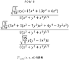
まず初めに、1つの送信機、及び本明細書では断らない限り検出器64であることが仮定される摂動要素中で送信機によって形成された1つの展開点について考慮する。1つの展開点は、検出器に基づく一組の(x,y,z)座標の原点(0,0,0)であることが簡素化のために仮定されると、原点からの1つの位置(x,y,z)にての磁気反応磁界に関する表現(3要素カラムベクトルとして表現される)は、

[C0]は原点について展開された、1〜3次の球面調和関数項に基づく、15要素のカラムベクトルであり([C]の展開された変形に関する表現は以下に示す)、
[Tspatial(x,y,z)]は、[C0]の球面調和関数項から誘導された3×15の空間転送行列である。
One transmitter First, consider one transmitter and one development point formed by the transmitter in a perturbing element that is assumed to be a detector 64 unless otherwise noted herein. One expansion point is assumed to be the origin (0,0,0) of a set of (x, y, z) coordinates based on the detector, for simplicity, one position from the origin. The expression for the magnetic reaction field at (x, y, z) (expressed as a three-element column vector) is
[C 0 ] is a 15-element column vector based on the 1st to 3rd order spherical harmonic function terms expanded about the origin (the expression relating to the expanded deformation of [C] is shown below)
[T spatial (x, y, z)] is a 3 × 15 spatial transfer matrix derived from the spherical harmonic term of [C 0 ].
図8A〜8Gは、本発明の一実施形態による、[Tspatial(x,y,z)]の要素それぞれを示す。 8A-8G illustrate each element of [T spatial (x, y, z)], according to one embodiment of the present invention.
5つの展開点(0,0,0)、(x1、y1、z1)、(x2、y2、z2)、(x3、y3、z3)、(x4、y4、z4)に関して、方程式(1)は次のようになる。
[C5]は75要素カラムベクトルである。
[Tspatial(x,y,z)(5)]は、それぞれの変位の座標により原点からそれぞれがオフセットしている、4つの[Tspatial]行列を[Tspatial(x,y,z)]と連結させることによって形成され、すなわち、
[C5]は、対応する展開点についてそれぞれが展開された球面調和関数項に基づく、5つのカラムベクトルをスタックすることによって形成される。すなわち、
[C 5 ] is a 75 element column vector.
[T spatial (x, y, z) (5)] represents four [T spatial ] matrices, each of which is offset from the origin by the coordinates of the respective displacements, [T spatial (x, y, z)]. Formed by connecting with, i.e.
[C 5 ] is formed by stacking five column vectors, each based on a spherical harmonic term expanded for the corresponding expansion point. That is,
1つの送信機からの磁界
領域30中の任意の点にての、任意の所定の送信機からの磁界は、位置パッドの製造プロセス中に実施される較正から計算されることができる。送信機の特性評価のために、検出器64の領域中の多くの点を考慮する。発明者らは、17個の点が適切であることがわかったが、他の任意の好都合な数が使用されてもよい。17個の点における磁界は、非摂動磁界の51要素のカラムベクトル[Bsatellite]によって表されることができる。
[C5]=[Treaction]・[Bsatellite] (6)
ここで、[Treaction]は、要素が検出器の反応特性を表す75×51の反応行列である。
Magnetic Field from One Transmitter The magnetic field from any given transmitter at any point in
[C 5 ] = [T reaction ] · [B satellite ] (6)
Here, [T reaction ] is a 75 × 51 reaction matrix whose elements represent the reaction characteristics of the detector.
一般的な場合
上記誘導を用いて、点(x、y、z)における検出器反応磁界のための表現式は、以下の方程式(7)として記述することができる。表現式は、検出器内に9個の送信機及び5個の展開点があるものと仮定する。
![]()
![]()
積[Tspatial(x,y,z)(5)].[Treaction]は、検出器で作成された5つの画像を有効に特性評価することが理解されるであろう。 Product [T spatial (x, y, z) (5)]. It will be appreciated that [T reaction ] effectively characterizes the five images produced by the detector.
方程式(7)は、以下に説明するように、システム20の較正段階及び操作段階の双方において使用することが可能である。
Equation (7) can be used in both the calibration and operation phases of the
いくつかの実施形態では、方程式(7)をそのまま用いるよりはむしろ、[Breac(x,y,z)]及び[Tspatial(x,y,z)(5)]を‖B(x,y,z)‖で割ることによって方程式を適応させるが、ここでB(x、y、z)は、(x、y、z)における送信機からの非摂動磁界である。発明者らは、このような適応は送信機磁界が弱い位置で重視され得、この磁界の測定における誤差を相殺することが可能であることがわかった。 In some embodiments, rather than directly using equation (7) is, [Breac (x, y, z)] and [T spatial (x, y, z) (5)] the ‖B (x, y , Z) adapt the equation by dividing by ‖, where B (x, y, z) is the unperturbed magnetic field from the transmitter at (x, y, z). The inventors have found that such adaptation can be emphasized at locations where the transmitter magnetic field is weak and can offset errors in the measurement of this magnetic field.
簡略化のために、本明細書の説明は、方程式(7)がそのまま用いられると仮定するが、当該技術分野における当業者は、上記の方程式(7)への適応を実現する実施形態に関して、必要な変更を加えて説明を改変することが可能であろう。 For simplicity, the description herein assumes that equation (7) is used as is, but those skilled in the art will be aware of an embodiment that realizes adaptation to equation (7) above. It will be possible to modify the description with the necessary changes.
較正段階
較正段階では、方程式(7)を用いて[Treaction]の値を見つける。
Calibration Stage In the calibration stage, Equation (7) is used to find the value of [T reaction ].
特定の位置(x、y、z)に関して、検出器が磁界を摂動させるような位置での検出器64による磁界と、磁界を摂動させないような位置での検出器による磁界との間の差を見つけることによって、[Breac(x,y,z)]の要素を見つけることが可能である。 For a particular position (x, y, z), the difference between the magnetic field due to the detector 64 at a position where the detector perturbs the magnetic field and the magnetic field due to the detector at a position where the magnetic field is not perturbed. By finding, it is possible to find the element of [Breac (x, y, z)].
[Tspatial(5)(x,y,z)]の要素は、展開点の位置(方程式(2)を参照)が必要に応じて方程式で使用されることを想定して、図8に示される方程式から見つけることが可能である。 The elements of [T spatial (5) (x, y, z)] are shown in FIG. 8, assuming that the position of the expansion point (see equation (2)) is used in the equation as needed. Can be found from the equation.
このようにして、方程式(7)では、[Treaction]以外のすべての項が解明される。 In this way, in Equation (7), all terms other than [T reaction ] are solved.
[Treaction]は、当該技術分野における当業者にはよく知られた方法によって、方程式(7)を操作することで見つけることが可能である。[Treaction]を見つけるためのそのような方法の1つでは、[Breac(x,y,z)]及び[Treaction]をベクトル化し、Kronecker積
![]()
![]()
vec[Treaction]は、
![]()
![]()
このような方法は、(x、y、z)の1つの値、また特定の位置にある検出器(及び結果的には展開点)に関する[Treaction]を見つける。 Such a method finds one value of (x, y, z), and [T reaction ] for the detector (and consequently the expansion point) at a particular position.
較正段階では、マッパー70は、Nセンサを用いて、(x、y、z)のN値の測定を行うことが想定される。N点(x1、y1、z1)、...、(xN、yN、zN)に関して、次に示す式の行列をスタックすることによって、方程式(10)が書き換えられてもよい。
方程式(11)は、1つの検出器位置に関するものであり、次のように書き換えられてもよい。
![]()
![]()
較正段階では、検出器がM位置に配置されていると仮定し、行列の更なるスタックによって、方程式(12)は方程式(13)を構成するように適合されてもよい。
方程式(10)を解くための上述された方法に関しては、方程式(13)の[Treaction]に関する解が、
N=50及びM=30であるような一実施形態では、行列
較正段階は、通常、各摂動要素に関して、[Treaction]を見つけるよう実行される。したがって、コリメーター62及び検出器64が、唯一の摂動要素であると想定されるような蛍光透視鏡60に関しては、行列[Treaction]collimator及び行列[Treaction]detectorが見出される。[Treaction]collimatorを見つけるために、典型的には、蛍光透視鏡位置を変えると同時に手術台24が下げられ、その結果、検出器の影響は無視できるほど小さい。同様に、[Treaction]detectorを見つけるために、典型的には、蛍光透視鏡位置を変えると同時に手術台が上げられる。
The calibration phase is usually performed to find [T reaction ] for each perturbing element. Thus, for a
操作段階
操作段階では、較正段階で決定された[Treaction]の値を、方程式(7)に置換して、[Breac(x,y,z)]の値を見つける。もし1つを超える摂動要素があれば、反応磁界は、各要素からの[Breac(x,y,z)]のそれぞれの値の線形重畳であると仮定される。
Operation Phase In the operation phase, the value of [T reaction ] determined in the calibration phase is replaced with equation (7) to find the value of [Breac (x, y, z)]. If there are more than one perturbing element, the reaction field is assumed to be a linear superposition of the respective values of [Breac (x, y, z)] from each element.
適合蛍光透視鏡位置
図1に戻って参照すると、本発明の実施形態は、位置パッドに対して蛍光透視鏡60を適応的に配置するための方法を提供する。本方法は、基準の蛍光透視鏡フレームの予備的位置合わせが、任意の便利なプロセスによって、基準の位置パッドフレームで実施されたことを仮定する。このようなプロセスは、通常、蛍光透視鏡を用いて手術台24上の物体を撮像し、位置パッドのコイル32から物体までの距離を見つけ、画像を距離と比較することによって位置合わせを実行する。本プロセスは、通常、蛍光透視鏡の多くの異なる位置に適用され、コリメーターから検出器までの距離、及び物体を撮像する際の蛍光透視鏡の向きなどのような、蛍光透視鏡の既知のパラメータを用いる。予備的位置合わせは、一般的に、システム20で患者に施される臨床的処置の開始時に実施される。
Adaptive Fluoroscope Position Referring back to FIG. 1, embodiments of the present invention provide a method for adaptively positioning a
処置中に、3つのパッチ電極が通常患者の胸部に配置され、本明細書では、各パッチは、センサ76に類似したセンサを含むと仮定する。これらのパッチセンサは、通常、位置パッドに対して位置が異なるが、これらの位置は、これらが検出する磁界から推定されてもよい。すべての5つのセンサ(それぞれが3つのコイルを有する)が、コイル32からの9つの送信された磁界に、同様にコリメーター及び検出器からの画像磁界に曝されて、その結果、プロセッサ52に入力される、センサからの135個の独立して数値が付けられた測定された信号(本明細書では「Meas」と称される)が常に存在する。この数の信号は、蛍光透視鏡及びその構成要素の位置及び向きを完全に説明するのに必要な自由度数に関して、重複性の高い値のセットを提供すると理解されであろう。そのうえ、センサ76にて測定された未摂動磁界は、センサにおいて反応磁界の直接的測定を可能にする。
During the procedure, it is assumed that three patch electrodes are usually placed on the patient's chest and each patch includes a sensor similar to
このようにして、プロセッサ52は、検出器64及びコリメーター62の位置はもとより、蛍光透視鏡の位置及び向きを計算するために、信号Measを用いることができる。プロセッサは、以下のコスト関数を計算する。
![]()
![]()
![]()
φfluoroは蛍光透視鏡60の高度であり、
θfluoroは蛍光透視鏡60の方位であり、
ddetは検出器64の距離であり、
dcolはコリメーター62の距離であり、
上記の変数のすべては、位置パッド軸及び原点に対して計算される。
In this way, the
![]()
![]()
![]()
φ fluoro is the height of the
θ fluoro is the orientation of the
d det is the distance of the detector 64;
d col is the distance of the
All of the above variables are calculated relative to the position pad axis and origin.
蛍光透視鏡、並びにその構成要素の位置及び向きを計算するために、プロセッサは、コスト関数Cを最適化する。最適化は、一般的に、Cの一次及びより高次の導関数の計算を伴うが、当該分野において既知の最適化のためのいかなる方法を用いてもよい。 In order to calculate the position and orientation of the fluoroscope and its components, the processor optimizes the cost function C. Optimization generally involves calculating the first and higher order derivatives of C, but any method for optimization known in the art may be used.
上記説明は、磁界摂動要素である蛍光透視鏡の要素に言及したが、本発明の範囲は、他の摂動要素を含むことが理解されるであろう。例えば、プローブ22は、配列28によって発生した磁界を摂動させる金属構成要素を含んでもよく、これらの要素により発生した摂動は、蛍光透視鏡要素に関して本明細書中に記載されるような方法と実質的に類似した方法で相殺され得る。このような金属構成要素には、手術台又はその部品を挙げることができるが、これらに限定されるものではない。
Although the above description has referred to a fluoroscope element that is a magnetic field perturbation element, it will be understood that the scope of the present invention includes other perturbation elements. For example, the
したがって、上述の実施形態は一例として引用したものであり、本発明は上記に具体的に図示及び記載したものに限定されないことが認識されるであろう。むしろ本発明の範囲には、上記に述べた様々な特徴の組み合わせ及び下位の組み合わせ、並びに当業者であれば上記の説明文を読むことで想到されるであろう、先行技術に開示されていないそれらの変更及び改変が含まれるものである。 Accordingly, it will be appreciated that the embodiments described above are cited by way of example, and that the present invention is not limited to what has been particularly shown and described hereinabove. Rather, the scope of the present invention is not disclosed in the prior art, which would be conceived by one of ordinary skill in the art upon reading the above description, as well as combinations of various features and sub-combinations described above. These changes and modifications are included.
〔実施の態様〕
(1) 複数の磁気送信機を用いて、領域中に磁界を発生させることと、
磁界摂動要素を前記領域中に導入することと、
前記磁界摂動要素内の各磁気送信機の複数画像を特性評価することと、
前記特性評価された画像に基づいて、前記領域中で反応磁界を計算することと、
前記領域中にプローブを配置し、前記プローブにおける摂動した磁界を測定することと、
前記測定された摂動した磁界及び前記計算した反応磁界に対応して前記プローブの位置を決定することと、
を含む、方法。
(2) 前記磁界を発生させることが、前記磁界摂動要素が不在の前記磁界を測定することと、前記領域中に存在する前記磁界摂動要素を伴う前記磁界を測定することと、を含む、実施態様1に記載の方法。
(3) 前記磁界摂動要素を前記領域中に導入することが、前記磁界摂動要素の位置及び向きを、前記磁気送信機によって規定された軸に対して測定することを含む、実施態様1に記載の方法。
(4) 前記磁界摂動要素の前記位置及び前記向きを測定することが、前記反応磁界に対応して前記位置及び前記向きを適応的に計算することを含む、実施態様3に記載の方法。
(5) 前記複数画像を特性評価することが、前記複数画像が互いに対して所定の構成にあると仮定することを含む、実施態様1に記載の方法。
(6) 前記所定の構成が、矩形を含み、前記複数画像が、前記矩形の角部及び中心に位置する5つの画像を含む、実施態様5に記載の方法。
(7) 前記反応磁界を計算することが、球面調和関数展開により、前記磁界を計算することを含む、実施態様1に記載の方法。
(8) 前記反応磁界を計算することが、最大3次までの前記球面調和関数展開を実行することを含む、実施態様7に記載の方法。
(9) 前記球面調和関数展開により前記磁界を計算することが、前記展開を空間転送行列として設定することを含み、前記方法が、前記磁界摂動要素の特性を反応磁界行列として決定することを更に含み、前記反応磁界を計算することが、前記空間転送行列と前記反応磁界行列との積に対応する、実施態様7に記載の方法。
(10) 前記プローブを配置することが、患者の体内に前記プローブを配置することを含む、実施態様1に記載の方法。
Embodiment
(1) using a plurality of magnetic transmitters to generate a magnetic field in the region;
Introducing a magnetic field perturbing element into the region;
Characterizing multiple images of each magnetic transmitter in the magnetic field perturbing element;
Calculating a reaction magnetic field in the region based on the characterized image;
Placing a probe in the region and measuring a perturbed magnetic field at the probe;
Determining the position of the probe in response to the measured perturbed magnetic field and the calculated response magnetic field;
Including a method.
(2) generating the magnetic field includes measuring the magnetic field in the absence of the magnetic field perturbing element and measuring the magnetic field with the magnetic field perturbing element present in the region; A method according to
(3) The embodiment of
(4) The method of
5. The method of
(6) The method according to
(7) The method of
(8) The method of embodiment 7, wherein calculating the reaction magnetic field comprises performing the spherical harmonic expansion up to a third order.
(9) Calculating the magnetic field by the spherical harmonic expansion includes setting the expansion as a spatial transfer matrix, and the method further determines the characteristic of the magnetic field perturbation element as a reaction magnetic field matrix 8. The method of embodiment 7, wherein the calculating the reaction magnetic field corresponds to a product of the spatial transfer matrix and the reaction magnetic field matrix.
10. The method of
(11) 前記磁界摂動要素が、蛍光透視鏡の少なくとも1つのセクションを含む、実施態様1に記載の方法。
(12) 前記蛍光透視鏡の蛍光透視鏡軸を、前記送信機によって規定された軸に対して位置合わせすることを含む、実施態様11に記載の方法。
(13) 前記蛍光透視鏡軸を位置合わせすることが、前記送信機に固定するよう接続されたカメラで、前記蛍光透視鏡に取り付けられた基準マークの画像を作成することを含む、実施態様12に記載の方法。
(14) 前記磁界摂動要素を導入することが、前記画像に対応して前記磁界摂動要素の位置及び向きを測定することを含む、実施態様13に記載の方法。
(15) 領域中で磁界を発生するよう構成された複数の磁気送信機と、
前記領域中に導入された磁界摂動要素と、
プロセッサであって、
前記磁界摂動要素内の各磁気送信機の複数画像を特性評価し、
前記特性評価された画像に基づいて、前記領域中の反応磁界を計算し、
前記領域中に配置されたプローブにて摂動した磁界を測定し、
前記測定された摂動した磁界及び前記計算された反応磁界に対応して、前記プローブの位置を決定するよう構成される、プロセッサと、
を含む、装置。
(16) 前記プロセッサが、前記磁界摂動要素が不在の前記磁界を測定し、前記領域中に存在する前記磁気摂動要素を伴う前記磁界を測定するよう構成される、実施態様15に記載の装置。
(17) 前記プロセッサが、前記磁界摂動要素の位置及び向きを、前記磁気送信機によって規定された軸に対して測定するよう構成される、実施態様15に記載の装置。
(18) 前記磁界摂動要素の前記位置及び前記向きを測定することが、前記反応磁界に対応して前記位置及び前記向きを適応的に計算することを含む、実施態様17に記載の装置。
(19) 前記複数画像を特性評価することが、前記複数画像が互いに対して所定の構成にあると仮定することを含む、実施態様15に記載の装置。
(20) 前記所定の構成が、矩形を含み、前記複数画像が、前記矩形の角部及び中心に位置する5つの画像を含む、実施態様19に記載の装置。
11. The method of
12. The method of embodiment 11, comprising aligning a fluoroscopic axis of the fluoroscope with respect to an axis defined by the transmitter.
(13)
14. The method of
(15) a plurality of magnetic transmitters configured to generate a magnetic field in the region;
A magnetic field perturbing element introduced into the region;
A processor,
Characterizing multiple images of each magnetic transmitter in the magnetic field perturbing element;
Calculating a reaction magnetic field in the region based on the characterized image;
Measure the magnetic field perturbed by the probe placed in the region,
A processor configured to determine a position of the probe in response to the measured perturbed magnetic field and the calculated response magnetic field;
Including the device.
16. The apparatus of
17. The apparatus of
18. The apparatus of embodiment 17, wherein measuring the position and the orientation of the magnetic field perturbing element includes adaptively calculating the position and the orientation in response to the reaction magnetic field.
The apparatus of
(20) The apparatus according to embodiment 19, wherein the predetermined configuration includes a rectangle, and the plurality of images include five images located at corners and centers of the rectangle.
(21) 前記反応磁界を計算することが、球面調和関数展開により、前記磁界を計算することを含む、実施態様15に記載の装置。
(22) 前記反応磁界を計算することが、最大3次までの前記球面調和関数展開を実行することを含む、実施態様21に記載の装置。
(23) 前記球面調和関数展開により前記磁界を計算することが、前記展開を空間転送行列として設定することを含み、前記プロセッサが、前記磁界摂動要素の特性を反応磁界行列として決定するよう、及び前記空間転送行列と前記反応磁界行列との積に対応して前記反応磁界を計算するよう構成される、実施態様21に記載の装置。
(24) 前記プローブが、患者の体内に配置されている、実施態様15に記載の装置。
(25) 前記磁界摂動要素が、蛍光透視鏡の少なくとも1つのセクションを含む、実施態様15に記載の装置。
(26) 前記蛍光透視鏡の蛍光透視鏡軸を、前記送信機によって規定された軸に対して位置合わせすることを含む、実施態様25に記載の装置。
(27) 前記蛍光透視鏡軸を位置合わせすることが、前記送信機に固定するよう接続されたカメラで、前記蛍光透視鏡に取り付けられた基準マークの画像を作成することを含む、実施態様26に記載の装置。
(28) 前記プロセッサが、前記画像に対応して前記磁界摂動要素の位置及び向きを測定するよう構成される、実施態様27に記載の装置。
(29) 位置パッド上に、患者に磁界を発生させるよう構成された磁気送信機を据え付けることと、
前記位置パッドにそれぞれの固定された向きで位置パッドカメラを取り付けることと、
前記位置パッドに回転可能なカメラを接続させることと、
前記患者を撮像するよう構成された蛍光透視鏡に、基準マークを取り付けることと、
前記蛍光透視鏡を、異なる位置に位置付けることと、
を含み、
各位置に関しては、
前記回転可能なカメラを既知の向きに配向させ、前記基準マークのそれぞれの画像を、前記回転可能なカメラ及び前記位置パッドカメラで作成することと、
前記位置パッドの軸に対して前記蛍光透視鏡の位置及び向きを位置合わせするよう、前記それぞれの画像を解析することと、
を含む、方法。
(30) 前記回転可能なカメラを前記位置パッドから取り外すことと、前記位置パッドカメラにより作成された前記基準マークの前記画像のみを用いて、前記位置パッドの前記軸に対して前記蛍光透視鏡の前記位置及び向きを決定することと、を含む、実施態様29に記載の方法。
21. The apparatus of
22. The apparatus of
(23) calculating the magnetic field by the spherical harmonic expansion includes setting the expansion as a spatial transfer matrix, the processor determining a characteristic of the magnetic field perturbation element as a reaction magnetic field matrix; and 23. The apparatus of
24. The apparatus according to
The apparatus according to
26. The apparatus of
27. The
28. The apparatus of embodiment 27, wherein the processor is configured to measure a position and orientation of the magnetic field perturbing element in response to the image.
(29) installing on the position pad a magnetic transmitter configured to generate a magnetic field in the patient;
Attaching a position pad camera in each fixed orientation to the position pad;
Connecting a rotatable camera to the position pad;
Attaching a fiducial mark to a fluoroscope configured to image the patient;
Positioning the fluoroscope at different positions;
Including
For each position,
Orienting the rotatable camera in a known orientation and creating an image of each of the fiducial marks with the rotatable camera and the position pad camera;
Analyzing each of the images to align the position and orientation of the fluoroscope with respect to the axis of the position pad;
Including a method.
(30) removing the rotatable camera from the position pad, and using only the image of the reference mark created by the position pad camera, the fluoroscope with respect to the axis of the position pad. 30. The method of embodiment 29, comprising determining the position and orientation.
(31) 前記位置パッドカメラを前記位置パッドに取り付けることが、取り外し可能なジグを前記位置パッドに取り付けることと、前記カメラで前記ジグを撮像することによって、前記位置パッドカメラを前記それぞれの固定された向きに整列させることと、を含む、実施態様29に記載の方法。
(32) 位置パッドと、
前記位置パッド上に据え付けられ、患者に磁界を発生させるよう構成された磁気送信機と、
それぞれの固定した向きで前記位置パッドに取り付けられた位置パッドカメラと、
前記位置パッドに接続された回転可能なカメラと、
前記患者を撮像するよう構成された蛍光透視鏡と、
前記蛍光透視鏡に取り付けられた基準マークと、
プロセッサであって、
異なる位置に前記蛍光透視鏡を位置付けるよう構成され、各位置に関しては、
前記回転可能なカメラを既知の向きに配向させ、前記回転可能なカメラ及び前記位置パッドカメラで前記基準マークのそれぞれの画像を作成するよう、並びに
前記位置パッドの軸に対して前記蛍光透視鏡の位置及び向きを位置合わせするよう、前記それぞれの画像を解析するよう構成された、プロセッサと、
を含む、装置。
(33) 前記プロセッサが、前記回転可能なカメラが前記位置パッドから取り外される間に、前記位置パッドカメラによって作成された前記基準マークの前記画像のみを用いて、前記位置パッドの前記軸に対して前記蛍光透視鏡の前記位置及び向きを決定するよう構成される、実施態様32に記載の装置。
(34) 前記位置パッドに取り付けられるよう構成された取り外し可能なジグを含み、前記位置パッドカメラが、前記カメラで前記ジグを撮像することによって、前記それぞれの固定された向きに整列するよう構成される、実施態様32に記載の装置。
(31) attaching the position pad camera to the position pad; attaching a removable jig to the position pad; and imaging the jig with the camera to fix the position pad camera to each of the fixed positions. 30. The method of embodiment 29, comprising: aligning in a different orientation.
(32) a position pad;
A magnetic transmitter mounted on the position pad and configured to generate a magnetic field in the patient;
A position pad camera attached to the position pad in each fixed orientation;
A rotatable camera connected to the position pad;
A fluoroscope configured to image the patient;
A reference mark attached to the fluoroscope;
A processor,
It is configured to position the fluoroscope at different positions, and for each position,
Orienting the rotatable camera in a known orientation, creating an image of each of the fiducial marks with the rotatable camera and the position pad camera, and of the fluoroscope with respect to the axis of the position pad A processor configured to analyze the respective images to align position and orientation;
Including the device.
(33) The processor uses only the image of the fiducial mark created by the position pad camera while the rotatable camera is removed from the position pad, with respect to the axis of the position pad. 33. The apparatus according to embodiment 32, configured to determine the position and orientation of the fluoroscope.
(34) including a removable jig configured to be attached to the position pad, wherein the position pad camera is configured to align in the respective fixed orientation by imaging the jig with the camera. The device of embodiment 32.
Claims (14)
前記領域中に導入された金属成分を含む、磁界摂動要素と、
プロセッサであって、
前記磁界摂動要素に起因する磁界である、反応磁界が、前記磁界摂動要素における前記反応磁界の発生源として仮定されたポイント源に基づき計算され、
前記領域中に配置されたプローブにて摂動した磁界が測定され、
前記測定された摂動した磁界及び前記計算された反応磁界に対応して、前記プローブの位置が決定されるよう構成される、プロセッサと、
を含む、装置。 A plurality of magnetic transmitters configured to generate a magnetic field in an imaging region of the fluoroscope ;
A magnetic field perturbation element comprising a metal component introduced into the region;
A processor,
A reaction field , which is a magnetic field resulting from the magnetic field perturbation element, is calculated based on a point source assumed as a source of the reaction magnetic field in the magnetic field perturbation element ;
Magnetic field perturbations at arranged probes in the area is measured,
In response to the measured perturbed magnetic field and the calculated magnetic reaction fields, configured to position the probe is determined, and the processor,
Including the device.
Applications Claiming Priority (2)
| Application Number | Priority Date | Filing Date | Title |
|---|---|---|---|
| US12/975,915 US8812079B2 (en) | 2010-12-22 | 2010-12-22 | Compensation for magnetic disturbance due to fluoroscope |
| US12/975,915 | 2010-12-22 |
Related Child Applications (1)
| Application Number | Title | Priority Date | Filing Date |
|---|---|---|---|
| JP2016168988A Division JP6189509B2 (en) | 2010-12-22 | 2016-08-31 | Cancellation of magnetic disturbance caused by fluoroscope |
Publications (2)
| Publication Number | Publication Date |
|---|---|
| JP2012130703A JP2012130703A (en) | 2012-07-12 |
| JP6000544B2 true JP6000544B2 (en) | 2016-09-28 |
Family
ID=45442953
Family Applications (2)
| Application Number | Title | Priority Date | Filing Date |
|---|---|---|---|
| JP2011279383A Active JP6000544B2 (en) | 2010-12-22 | 2011-12-21 | Cancellation of magnetic disturbance caused by fluoroscope |
| JP2016168988A Active JP6189509B2 (en) | 2010-12-22 | 2016-08-31 | Cancellation of magnetic disturbance caused by fluoroscope |
Family Applications After (1)
| Application Number | Title | Priority Date | Filing Date |
|---|---|---|---|
| JP2016168988A Active JP6189509B2 (en) | 2010-12-22 | 2016-08-31 | Cancellation of magnetic disturbance caused by fluoroscope |
Country Status (8)
| Country | Link |
|---|---|
| US (1) | US8812079B2 (en) |
| EP (3) | EP3403610B1 (en) |
| JP (2) | JP6000544B2 (en) |
| CN (2) | CN102525471B (en) |
| AU (1) | AU2011254069B2 (en) |
| CA (1) | CA2762262C (en) |
| ES (1) | ES2792111T3 (en) |
| IL (1) | IL216807B (en) |
Families Citing this family (53)
| Publication number | Priority date | Publication date | Assignee | Title |
|---|---|---|---|---|
| US8672837B2 (en) | 2010-06-24 | 2014-03-18 | Hansen Medical, Inc. | Methods and devices for controlling a shapeable medical device |
| US9622714B2 (en) * | 2011-06-08 | 2017-04-18 | Siemens Medical Solutions Usa, Inc. | System and method for photographic determination of multichannel collimator channel pointing directions |
| US8818486B2 (en) * | 2012-07-12 | 2014-08-26 | Biosense Webster (Israel) Ltd. | Position and orientation algorithm for a single axis sensor |
| US9310446B2 (en) * | 2012-10-18 | 2016-04-12 | Analog Devices, Inc. | Magnetic field direction detector |
| US10441236B2 (en) * | 2012-10-19 | 2019-10-15 | Biosense Webster (Israel) Ltd. | Integration between 3D maps and fluoroscopic images |
| US9057600B2 (en) | 2013-03-13 | 2015-06-16 | Hansen Medical, Inc. | Reducing incremental measurement sensor error |
| US9629595B2 (en) | 2013-03-15 | 2017-04-25 | Hansen Medical, Inc. | Systems and methods for localizing, tracking and/or controlling medical instruments |
| US9014851B2 (en) | 2013-03-15 | 2015-04-21 | Hansen Medical, Inc. | Systems and methods for tracking robotically controlled medical instruments |
| US9271663B2 (en) | 2013-03-15 | 2016-03-01 | Hansen Medical, Inc. | Flexible instrument localization from both remote and elongation sensors |
| US11020016B2 (en) | 2013-05-30 | 2021-06-01 | Auris Health, Inc. | System and method for displaying anatomy and devices on a movable display |
| US9186115B2 (en) * | 2013-07-01 | 2015-11-17 | Siemens Medical Solutions Usa, Inc. | Method and apparatus for compensating for magnetic field during medical imaging |
| US9696131B2 (en) * | 2013-12-24 | 2017-07-04 | Biosense Webster (Israel) Ltd. | Adaptive fluoroscope location for the application of field compensation |
| US9638820B2 (en) * | 2014-03-03 | 2017-05-02 | Biosense Webster (Israel) Ltd. | Calibration jig for a flat location pad |
| US20190004122A1 (en) * | 2014-04-25 | 2019-01-03 | Purdue Research Foundation | Wireless position sensing using magnetic field of single transmitter |
| US10213133B2 (en) * | 2014-12-22 | 2019-02-26 | Biosense Webster (Israel) Ltd | Modeling of a magnetic field |
| US10285760B2 (en) | 2015-02-04 | 2019-05-14 | Queen's University At Kingston | Methods and apparatus for improved electromagnetic tracking and localization |
| US10307078B2 (en) | 2015-02-13 | 2019-06-04 | Biosense Webster (Israel) Ltd | Training of impedance based location system using registered catheter images |
| US10105117B2 (en) | 2015-02-13 | 2018-10-23 | Biosense Webster (Israel) Ltd. | Compensation for heart movement using coronary sinus catheter images |
| CN107743381A (en) * | 2015-06-12 | 2018-02-27 | 皇家飞利浦有限公司 | Electromagnetic equipment tracks |
| US9727963B2 (en) | 2015-09-18 | 2017-08-08 | Auris Surgical Robotics, Inc. | Navigation of tubular networks |
| US10359458B2 (en) * | 2015-10-05 | 2019-07-23 | Covidien Lp | Systems and methods for automated mapping and accuracy-testing |
| US10143526B2 (en) | 2015-11-30 | 2018-12-04 | Auris Health, Inc. | Robot-assisted driving systems and methods |
| US11187763B2 (en) | 2016-03-23 | 2021-11-30 | Analog Devices International Unlimited Company | Offset compensation for magnetic field detector |
| EP3432794B1 (en) * | 2016-05-03 | 2020-09-09 | St. Jude Medical International Holding S.à r.l. | Magnetic field distortion detection and correction in a magnetic localization system |
| US10244926B2 (en) | 2016-12-28 | 2019-04-02 | Auris Health, Inc. | Detecting endolumenal buckling of flexible instruments |
| WO2018183727A1 (en) | 2017-03-31 | 2018-10-04 | Auris Health, Inc. | Robotic systems for navigation of luminal networks that compensate for physiological noise |
| US10022192B1 (en) | 2017-06-23 | 2018-07-17 | Auris Health, Inc. | Automatically-initialized robotic systems for navigation of luminal networks |
| JP7330902B2 (en) * | 2017-06-28 | 2023-08-22 | オーリス ヘルス インコーポレイテッド | Electromagnetic distortion detection |
| JP7317723B2 (en) | 2017-06-28 | 2023-07-31 | オーリス ヘルス インコーポレイテッド | Electromagnetic field distortion detection |
| US10739165B2 (en) | 2017-07-05 | 2020-08-11 | Analog Devices Global | Magnetic field sensor |
| US11058493B2 (en) | 2017-10-13 | 2021-07-13 | Auris Health, Inc. | Robotic system configured for navigation path tracing |
| US10555778B2 (en) | 2017-10-13 | 2020-02-11 | Auris Health, Inc. | Image-based branch detection and mapping for navigation |
| US11510736B2 (en) | 2017-12-14 | 2022-11-29 | Auris Health, Inc. | System and method for estimating instrument location |
| CN110809453B (en) | 2017-12-18 | 2023-06-06 | 奥瑞斯健康公司 | Method and system for instrument tracking and navigation within a luminal network |
| CN110891469B (en) | 2018-03-28 | 2023-01-13 | 奥瑞斯健康公司 | System and method for registration of positioning sensors |
| EP3773304A4 (en) | 2018-03-28 | 2021-12-22 | Auris Health, Inc. | Systems and methods for displaying estimated location of instrument |
| US10905499B2 (en) | 2018-05-30 | 2021-02-02 | Auris Health, Inc. | Systems and methods for location sensor-based branch prediction |
| CN110831481B (en) | 2018-05-31 | 2022-08-30 | 奥瑞斯健康公司 | Path-based navigation of tubular networks |
| KR102567087B1 (en) | 2018-05-31 | 2023-08-17 | 아우리스 헬스, 인코포레이티드 | Robotic systems and methods for navigation of luminal networks detecting physiological noise |
| MX2020012904A (en) | 2018-05-31 | 2021-02-26 | Auris Health Inc | Image-based airway analysis and mapping. |
| KR20210096622A (en) * | 2018-11-18 | 2021-08-05 | 트리그 메디컬 리미티드 | Spatial Registration Method for Imaging Devices |
| US20200237459A1 (en) | 2019-01-25 | 2020-07-30 | Biosense Webster (Israel) Ltd. | Flexible multi-coil tracking sensor |
| US20200372409A1 (en) * | 2019-05-24 | 2020-11-26 | Boston Scientific Scimed Inc. | Electromagnetic distortion compensation for device tracking |
| IT201900014559A1 (en) * | 2019-08-09 | 2021-02-09 | Mectron S P A | ASSEMBLY INSERT WITH RADIOFREQUENCY IDENTIFIER |
| WO2021038469A1 (en) | 2019-08-30 | 2021-03-04 | Auris Health, Inc. | Systems and methods for weight-based registration of location sensors |
| WO2021038495A1 (en) | 2019-08-30 | 2021-03-04 | Auris Health, Inc. | Instrument image reliability systems and methods |
| EP4025921A4 (en) | 2019-09-03 | 2023-09-06 | Auris Health, Inc. | Electromagnetic distortion detection and compensation |
| CA3093980C (en) * | 2019-09-26 | 2023-10-31 | Ascension Technology Corporation | Reconfigurable transmitter array for electromagnetic tracking systems |
| US11504023B2 (en) | 2019-12-16 | 2022-11-22 | Biosense Webster (Israel) Ltd. | Sparse calibration of magnetic field created by coils in metal-rich environment |
| WO2021137108A1 (en) | 2019-12-31 | 2021-07-08 | Auris Health, Inc. | Alignment interfaces for percutaneous access |
| CN114901192A (en) | 2019-12-31 | 2022-08-12 | 奥瑞斯健康公司 | Alignment technique for percutaneous access |
| CN114901194A (en) | 2019-12-31 | 2022-08-12 | 奥瑞斯健康公司 | Anatomical feature identification and targeting |
| CN112089491B (en) * | 2020-08-18 | 2023-12-19 | 上海精劢医疗科技有限公司 | Magnetic field deformation calibration tool and method in electromagnetic navigation system |
Family Cites Families (30)
| Publication number | Priority date | Publication date | Assignee | Title |
|---|---|---|---|---|
| US5767669A (en) | 1996-06-14 | 1998-06-16 | Ascension Technology Corporation | Magnetic field position and orientation measurement system with dynamic eddy current rejection |
| US6147480A (en) | 1997-10-23 | 2000-11-14 | Biosense, Inc. | Detection of metal disturbance |
| US7366562B2 (en) * | 2003-10-17 | 2008-04-29 | Medtronic Navigation, Inc. | Method and apparatus for surgical navigation |
| US6400139B1 (en) | 1999-11-01 | 2002-06-04 | Polhemus Inc. | Methods and apparatus for electromagnetic position and orientation tracking with distortion compensation |
| US6484118B1 (en) * | 2000-07-20 | 2002-11-19 | Biosense, Inc. | Electromagnetic position single axis system |
| IL137520A (en) | 2000-07-25 | 2010-06-16 | Elbit Systems Ltd | Estimating position and orientation in electromagnetic systems |
| CA2348135A1 (en) | 2001-05-17 | 2002-11-17 | Cedara Software Corp. | 3-d navigation for x-ray imaging system |
| US6774624B2 (en) | 2002-03-27 | 2004-08-10 | Ge Medical Systems Global Technology Company, Llc | Magnetic tracking system |
| US7065393B2 (en) | 2002-07-11 | 2006-06-20 | Cedara Software Corp. | Apparatus, system and method of calibrating medical imaging systems |
| US6714008B1 (en) | 2002-07-29 | 2004-03-30 | The United States Of America As Represented By The Secretary Of The Navy | Gradiometric measurement methodology for determining magnetic fields of large objects |
| WO2004052205A1 (en) * | 2002-12-11 | 2004-06-24 | Philips Intellectual Property & Standards Gmbh | C-arm x-ray apparatus having means of calibration |
| US7974680B2 (en) * | 2003-05-29 | 2011-07-05 | Biosense, Inc. | Hysteresis assessment for metal immunity |
| CN1901835A (en) * | 2003-11-14 | 2007-01-24 | 通用电气公司 | System and method for distortion reduction in an electromagnetic tracker |
| US20050107687A1 (en) | 2003-11-14 | 2005-05-19 | Anderson Peter T. | System and method for distortion reduction in an electromagnetic tracker |
| US7062391B2 (en) * | 2004-03-12 | 2006-06-13 | Vsm Medtech Systems Inc. | Motion compensation in biomagnetic measurement |
| US20060229515A1 (en) * | 2004-11-17 | 2006-10-12 | The Regents Of The University Of California | Fiber optic evaluation of tissue modification |
| US7657075B2 (en) | 2005-05-06 | 2010-02-02 | Stereotaxis, Inc. | Registration of three dimensional image data with X-ray imaging system |
| DE102005023167B4 (en) | 2005-05-19 | 2008-01-03 | Siemens Ag | Method and device for registering 2D projection images relative to a 3D image data set |
| US8000772B2 (en) * | 2005-10-19 | 2011-08-16 | Biosense Webster, Inc. | Metal immunity in a reverse magnetic system |
| US7532997B2 (en) | 2006-04-17 | 2009-05-12 | General Electric Company | Electromagnetic tracking using a discretized numerical field model |
| US8040127B2 (en) * | 2006-08-15 | 2011-10-18 | General Electric Company | Multi-sensor distortion mapping method and system |
| US10016148B2 (en) * | 2006-09-27 | 2018-07-10 | General Electric Company | Method and apparatus for correction of multiple EM sensor positions |
| US7917337B2 (en) * | 2006-09-29 | 2011-03-29 | Optichron, Inc. | Adaptive self-linearization with separation filter |
| US20080183064A1 (en) | 2007-01-30 | 2008-07-31 | General Electric Company | Multi-sensor distortion detection method and system |
| US20080228065A1 (en) * | 2007-03-13 | 2008-09-18 | Viswanathan Raju R | System and Method for Registration of Localization and Imaging Systems for Navigational Control of Medical Devices |
| DE102007019827A1 (en) * | 2007-04-26 | 2008-11-06 | Siemens Ag | System and method for determining the position of an instrument |
| WO2008154183A2 (en) | 2007-06-05 | 2008-12-18 | Ascension Technology Corporation | Systems and methods for compensating for large moving objects in magnetic-tracking environments |
| US7995864B2 (en) | 2007-07-03 | 2011-08-09 | General Electric Company | Method and system for performing image registration |
| US20090082665A1 (en) * | 2007-09-26 | 2009-03-26 | General Electric Company | System and method for tracking medical device |
| FR2941861B1 (en) * | 2009-02-12 | 2012-06-22 | Gen Electric | METHOD OF CALIBRATING THE RELATIVE POSITION OF A TABLE AND A C-ARM OF A MEDICAL IMAGING SYSTEM |
-
2010
- 2010-12-22 US US12/975,915 patent/US8812079B2/en active Active
-
2011
- 2011-12-07 IL IL216807A patent/IL216807B/en active IP Right Grant
- 2011-12-15 CA CA2762262A patent/CA2762262C/en active Active
- 2011-12-15 AU AU2011254069A patent/AU2011254069B2/en active Active
- 2011-12-21 JP JP2011279383A patent/JP6000544B2/en active Active
- 2011-12-21 EP EP18177011.6A patent/EP3403610B1/en active Active
- 2011-12-21 EP EP11194809.7A patent/EP2468208B1/en active Active
- 2011-12-21 ES ES18177011T patent/ES2792111T3/en active Active
- 2011-12-21 EP EP17176440.0A patent/EP3241495B1/en active Active
- 2011-12-22 CN CN201110461552.9A patent/CN102525471B/en active Active
- 2011-12-22 CN CN201510029457.XA patent/CN104665833B/en active Active
-
2016
- 2016-08-31 JP JP2016168988A patent/JP6189509B2/en active Active
Also Published As
| Publication number | Publication date |
|---|---|
| IL216807A0 (en) | 2012-01-31 |
| IL216807B (en) | 2018-01-31 |
| CN102525471B (en) | 2016-03-16 |
| EP2468208A2 (en) | 2012-06-27 |
| CN102525471A (en) | 2012-07-04 |
| JP6189509B2 (en) | 2017-08-30 |
| AU2011254069A1 (en) | 2012-07-12 |
| US20120165656A1 (en) | 2012-06-28 |
| AU2011254069B2 (en) | 2014-10-02 |
| JP2016195923A (en) | 2016-11-24 |
| JP2012130703A (en) | 2012-07-12 |
| EP2468208B1 (en) | 2017-10-25 |
| ES2792111T3 (en) | 2020-11-10 |
| EP3403610A1 (en) | 2018-11-21 |
| EP3241495B1 (en) | 2018-06-13 |
| EP3403610B1 (en) | 2020-03-25 |
| EP2468208A3 (en) | 2012-09-05 |
| CN104665833A (en) | 2015-06-03 |
| EP3241495A1 (en) | 2017-11-08 |
| CA2762262A1 (en) | 2012-06-22 |
| CA2762262C (en) | 2019-07-23 |
| CN104665833B (en) | 2017-03-29 |
| US8812079B2 (en) | 2014-08-19 |
Similar Documents
| Publication | Publication Date | Title |
|---|---|---|
| JP6189509B2 (en) | Cancellation of magnetic disturbance caused by fluoroscope | |
| CN103767683B (en) | Integration between 3D scaling graphs and fluoroscopic image | |
| AU2014277683B2 (en) | Adaptive fluoroscope location for the application of field compensation | |
| US8082020B2 (en) | Distortion-immune position tracking using redundant magnetic field measurements | |
| JP5675841B2 (en) | Motion compensation in moving organs using position reference sensors | |
| US7532997B2 (en) | Electromagnetic tracking using a discretized numerical field model | |
| MX2008007160A (en) | Water powered hose reel. | |
| WO2019210065A2 (en) | Position determination system and method | |
| CN109310365B (en) | Magnetic field distortion detection and correction in magnetic positioning system |
Legal Events
| Date | Code | Title | Description |
|---|---|---|---|
| A621 | Written request for application examination |
Free format text: JAPANESE INTERMEDIATE CODE: A621 Effective date: 20141030 |
|
| A977 | Report on retrieval |
Free format text: JAPANESE INTERMEDIATE CODE: A971007 Effective date: 20150930 |
|
| A131 | Notification of reasons for refusal |
Free format text: JAPANESE INTERMEDIATE CODE: A131 Effective date: 20151020 |
|
| A601 | Written request for extension of time |
Free format text: JAPANESE INTERMEDIATE CODE: A601 Effective date: 20160120 |
|
| A521 | Request for written amendment filed |
Free format text: JAPANESE INTERMEDIATE CODE: A523 Effective date: 20160216 |
|
| TRDD | Decision of grant or rejection written | ||
| A01 | Written decision to grant a patent or to grant a registration (utility model) |
Free format text: JAPANESE INTERMEDIATE CODE: A01 Effective date: 20160802 |
|
| A61 | First payment of annual fees (during grant procedure) |
Free format text: JAPANESE INTERMEDIATE CODE: A61 Effective date: 20160831 |
|
| R150 | Certificate of patent or registration of utility model |
Ref document number: 6000544 Country of ref document: JP Free format text: JAPANESE INTERMEDIATE CODE: R150 |
|
| R250 | Receipt of annual fees |
Free format text: JAPANESE INTERMEDIATE CODE: R250 |
|
| R250 | Receipt of annual fees |
Free format text: JAPANESE INTERMEDIATE CODE: R250 |
|
| R250 | Receipt of annual fees |
Free format text: JAPANESE INTERMEDIATE CODE: R250 |
|
| R250 | Receipt of annual fees |
Free format text: JAPANESE INTERMEDIATE CODE: R250 |
|
| R250 | Receipt of annual fees |
Free format text: JAPANESE INTERMEDIATE CODE: R250 |