JP6000360B2 - Method and apparatus for obtaining a stationary signal for diagnosing an electromechanical system - Google Patents
Method and apparatus for obtaining a stationary signal for diagnosing an electromechanical system Download PDFInfo
- Publication number
- JP6000360B2 JP6000360B2 JP2014532263A JP2014532263A JP6000360B2 JP 6000360 B2 JP6000360 B2 JP 6000360B2 JP 2014532263 A JP2014532263 A JP 2014532263A JP 2014532263 A JP2014532263 A JP 2014532263A JP 6000360 B2 JP6000360 B2 JP 6000360B2
- Authority
- JP
- Japan
- Prior art keywords
- signal
- vector
- samples
- dimensionless
- divided individual
- Prior art date
- Legal status (The legal status is an assumption and is not a legal conclusion. Google has not performed a legal analysis and makes no representation as to the accuracy of the status listed.)
- Active
Links
Images


Classifications
-
- G—PHYSICS
- G01—MEASURING; TESTING
- G01R—MEASURING ELECTRIC VARIABLES; MEASURING MAGNETIC VARIABLES
- G01R31/00—Arrangements for testing electric properties; Arrangements for locating electric faults; Arrangements for electrical testing characterised by what is being tested not provided for elsewhere
- G01R31/34—Testing dynamo-electric machines
- G01R31/343—Testing dynamo-electric machines in operation
Description
本発明は、回転機を用いる電気機械系であって、電気機械系の動作中に少なくとも1つの電気的信号または機械的信号を測定する電気機械系の診断を行うための定常信号を求める方法に関する。本発明は特に、モータやジェネレータの状態モニタリングに用いられる。 The present invention relates to a method for obtaining a stationary signal for diagnosing an electromechanical system that measures at least one electrical signal or a mechanical signal during operation of the electromechanical system using an electric rotating machine . The present invention is particularly used for monitoring the state of motors and generators.
本発明の背景技術
ここで記載する従来技術は、電流信号の測定に基づく手法であるが、たとえば電圧や振動測定結果における加速度等の他の物理的信号にも同様に当てはまる場合がある。
Background Art of the Present Invention The prior art described here is a technique based on the measurement of a current signal, but may apply to other physical signals as well, such as acceleration in voltage and vibration measurement results, for example.
モータおよびジェネレータ、より広い用語では回転機は、電気機械系の重要な要素となっている。回転機と電源とを接続する電力ケーブルから測定できる電流を解析する手法は、電気機械系の状態をモニタリングする有効な手法であることが分かっている。回転機に誘導される電流は動作条件の変化とともに変化し、これはしばしば、交流電流電源の大きな電流の振幅や位相変調となって現れることが多いことが知られている。 Motors and generators, in broader terms rotating machines, have become an important element of electromechanical systems. It has been found that a technique for analyzing a current that can be measured from a power cable connecting a rotating machine and a power source is an effective technique for monitoring the state of an electromechanical system. It is known that the current induced in the rotating machine changes as the operating conditions change, and this often appears as a large current amplitude or phase modulation of the alternating current power supply.
定常動作状態では、電源ケーブルから測定される電流の変調を引き起こす原因となる不具合が数多く存在する。このような変調は典型的には周波数領域で、周波数の特定の帯域における振幅成分の増加として解析される。回転機の電力ケーブルから測定された電流信号の周波数スペクトラムの特定の周波数における振幅成分の解析は、電流徴候解析MCSAとの名称で知られている。近年、MCSAはモータの不具合の発生を検出して対処する標準的な手法になってきている。典型的には、監視対象の回転機にオンラインで直接給電がなされる場合、電源周波数は測定期間全体にわたって実質的に変化することがない。したがってMCSAは、オンラインで直接給電される回転機の解析に容易に適用することができる。というのも、電源周波数の変調は測定期間全体にわたって一貫性を有し、よって、ノイズと容易に区別できるからである。この手法を用いると、モータ状態を特定して、たとえば偏心率、ロータバー故障、ベアリング故障等の不具合を予測し、保守作業のスケジュールを立てることができる。 In steady state operation, there are a number of defects that cause modulation of the current measured from the power cable. Such modulation is typically analyzed in the frequency domain as an increase in amplitude component in a particular band of frequencies. Analysis of the amplitude component at a specific frequency of the frequency spectrum of the current signal measured from the power cable of the rotating machine is known by the name of current symptom analysis MCSA. In recent years, MCSA has become a standard method for detecting and dealing with the occurrence of motor failures. Typically, when the monitored rotating machine is directly powered online, the power supply frequency does not change substantially throughout the measurement period. Therefore, MCSA can be easily applied to the analysis of a rotating machine that is directly powered online. This is because the modulation of the power supply frequency is consistent throughout the measurement period and is therefore easily distinguishable from noise. Using this method, it is possible to identify the motor state, predict defects such as eccentricity, rotor bar failure, bearing failure, etc., and schedule maintenance work.
回転機の給電を可変速度ドライブにより行うことが多くなってきている。その場合、電源周波数が一定値になることは希であり、典型的には、所要トルクおよび所要磁束に応じて変化する。可変速度ドライブにより給電されるモータから記録される電流信号のこのような非定常特性により、複数の異なる個別の周波数において対象のピークが生じなくなってしまったり、この対象ピークとノイズ信号とを区別することが困難になってしまうので、MCSAの有効性が低下してしまう。さらに、対象のピークに電源周波数の高調波が重畳する可能性も高くなる。 Increasingly, rotating machines are powered by variable speed drives. In that case, the power supply frequency rarely becomes a constant value, and typically changes according to the required torque and the required magnetic flux. This unsteady characteristic of the current signal recorded from the motor fed by the variable speed drive can cause the target peak to cease to occur at several different individual frequencies or to distinguish this target peak from the noise signal The effectiveness of MCSA is reduced. Furthermore, the possibility that harmonics of the power supply frequency are superimposed on the target peak is increased.
米国特許公報US5461329明細書には、交流電源の電流搬送波の変動的な周波数に応じて測定電流信号のサンプリングレートを変化させる回路を、データ取得システムに組み込むことにより、非定常のモータ電流信号を解析する方法が記載されている。可変周波数クロックジェネレータがモータ電流信号を入力として受け取って、出力としてクロック信号を出力し、アナログデジタル変換器がこのクロック信号を使用してモータ電流信号をサンプリングする。前記可変周波数クロックジェネレータは、有利な形態では位相同期ループPLLを有する。サンプリングされたデータは、離散フーリエ変換を用いて周波数領域に変換され、対象の信号が解析される。可変周波数クロックを、特にPLLを用いて信号をサンプリングする方式の手法には制限が課される。基本的にPLLは、期待される対象の周波数に同調された内部フィルタを使用し、この対象の周波数は、モータの定格給電周波数の前後であると想定される。オンラインで直接給電されるモータの場合にはこのことが一般的に成り立つが、可変速度ドライブにより給電されるモータの場合、給電周波数は大きく変動する。幅広い周波数変動を扱える可変周波数クロックを生成するのに必要な回路は、対象の周波数が厳密に特定されていて有意に変動しない場合のシステムの同等の回路と比較して格段に複雑になる。さらに、測定された電流信号と、可変周波数クロックによる推定周波数との間には、避けられない遅延が生じる。その結果、モータ電流信号の給電周波数の変化と、これに対応する、アナログデジタル変換器のサンプリング周波数の変化との間に遅延が生じる。その上、モータ電流信号のサンプリングレートを調整するために用いられる回路はノイズに影響を受けやすく、このことにより、周波数の推定が不正確であることに起因して、サンプリングされた信号の相互間の一貫性が失われてしまう。電流徴候解析の場合、このように一貫性が失われると、問題の診断が誤った結果になってしまう。 In US Pat. No. 5,461,329, an unsteady motor current signal is analyzed by incorporating into a data acquisition system a circuit that changes the sampling rate of a measured current signal in accordance with the fluctuating frequency of a current carrier wave of an AC power supply How to do is described. A variable frequency clock generator receives a motor current signal as input and outputs a clock signal as output, and an analog-to-digital converter samples the motor current signal using this clock signal. The variable frequency clock generator advantageously has a phase locked loop PLL. The sampled data is transformed into the frequency domain using discrete Fourier transform, and the target signal is analyzed. Limitations are imposed on the method of sampling a signal using a variable frequency clock, particularly a PLL. Basically, the PLL uses an internal filter tuned to the expected target frequency, which is assumed to be around the motor's rated feed frequency. In the case of a motor that is directly powered online, this is generally true, but in the case of a motor that is powered by a variable speed drive, the feed frequency varies greatly. The circuitry required to generate a variable frequency clock that can handle a wide range of frequency variations is significantly more complex than the equivalent circuitry of a system where the frequency of interest is strictly specified and does not vary significantly. Furthermore, there is an unavoidable delay between the measured current signal and the estimated frequency from the variable frequency clock. As a result, a delay occurs between the change in the power supply frequency of the motor current signal and the corresponding change in the sampling frequency of the analog-digital converter. In addition, the circuit used to adjust the sampling rate of the motor current signal is sensitive to noise, which causes the frequency of the sampled signals to be Will lose consistency. In the case of current symptom analysis, this inconsistency results in an incorrect diagnosis of the problem.
本発明の概要
電気機械系を診断するための定常信号を求める本発明の方法の重要な特徴は、以下のステップを有することである。
・前記電気機械系のアナログ波形信号Sを測定するステップ。
・測定した波形信号Sを、
時点のベクトルと、
対応する振幅ベクトルと
を含む処理済み離散的信号SDPに変換するステップ。
・処理済み離散的信号SDPを複数の分割個別周期SDP1,SDP2・・・SDPnに分割するステップ。各分割個別周期SDP1,SDP2・・・SDPnは、他の分割個別周期のサンプル数と同数または異なる数のサンプルを有する。
・リサンプリング後の分割個別周期SDR1,SDR2・・・SDRnを得るためのリサンプリング手順によって、前記各分割個別周期SDP1,SDP2・・・SDPnのサンプル数を変更して、前記リサンプリング後の分割個別周期に含まれるサンプル数がすべて等しくなるようにするステップ。
・前記リサンプリング後の各個別周期SDR1,SDR2・・・SDRnごとの時点のベクトルを連続した整数のベクトルに置換して、無次元の分割個別周期SDN1,SDN2・・・SDNnを得るステップ。
・前記連続した無次元の分割個別周期からサンプルを順次並べて、複数の連続したサンプルのシーケンスを形成することにより、すべての無次元の分割個別周期SDN1,SDN2・・・SDNnを連結して1つの無次元離散的信号SNにまとめるステップ。
・前記無次元離散的信号(SN)における昇順の時点のベクトルに、連続する整数のベクトルを置換することにより、有次元化された定常信号(SNt)を得るステップ。
・前記有次元化された定常信号(SNt)を時間領域から周波数領域に変換することにより、対象となる周波数ベクトルと、これに対応する振幅ベクトルとを抽出する元になる周波数スペクトルを求めるステップ。
ただし、前記周波数ベクトルおよび振幅ベクトルは、電気機械系の診断に用いられ、可視化装置上で表示されるものである。
Summary of the Invention An important feature of the method of the invention for determining a stationary signal for diagnosing an electromechanical system is that it comprises the following steps.
Measuring the electromechanical analog waveform signal S;
・ Measured waveform signal S
A vector of points in time,
Converting to a processed discrete signal SDP comprising a corresponding amplitude vector.
A step of dividing the processed discrete signal S DP into a plurality of divided individual periods S DP1 , S DP2 ... S DPn . Each divided individual period S DP1 , S DP2 ... S DPn has the same or different number of samples as the number of samples in the other divided individual periods.
· The resampling procedure for obtaining divided individual cycle S DR1, S DR2 ··· S DRn after resampling, by changing the number of samples of each of the divided individual cycle S DP1, S DP2 ··· S DPn , Making all the numbers of samples included in the divided individual periods after the resampling equal.
· Each individual cycle of the re-sampled S DR1, S DR2 ··· S vector time per DRn continuous by replacing the integer vector, dimensionless divided individual cycle S DN1, S DN2 ··· S Obtaining DNn .
· Said sequence aligned samples from dividing the individual periods of continuous dimensionless, by forming a plurality of successive samples of the sequence, and concatenating all the dimensionless divided individual cycle S DN1, S DN2 ··· S DNn Combining them into one dimensionless discrete signal SN .
A step of obtaining a dimensionalized steady signal (S Nt ) by replacing a vector of successive integers with a vector in ascending order in the dimensionless discrete signal (S N ).
A step of obtaining a frequency spectrum from which a target frequency vector and an amplitude vector corresponding to the target frequency vector are extracted by converting the dimensionalized steady signal (S Nt ) from the time domain to the frequency domain. .
However, the frequency vector and the amplitude vector are used for diagnosis of an electromechanical system and are displayed on a visualization device.
有利には、上述の測定アナログ信号は電流信号である。有利には、電気機械系を診断するための方法は電流徴候解析である。これに代えて択一的に、前記測定アナログ信号を電圧信号とすることができる。また、これに代えて択一的に、前記測定アナログ信号をトルク信号とすることができる。さらに、これに代えて択一的に、前記測定アナログ信号を加速度または速度または振動運動とすることができる。 Advantageously, the measurement analog signal described above is a current signal. Advantageously, the method for diagnosing the electromechanical system is current signature analysis. Alternatively, the measurement analog signal can be a voltage signal. Alternatively, the measurement analog signal can alternatively be a torque signal. Further alternatively, the measurement analog signal can be acceleration or velocity or vibrational motion.
本発明の方法の主な利点は、従来技術にて周知となっている回転機の電気信号の解析技術の多くを、可変速度ドライブにより回転機の給電が行われるケースに適用できることである。さらに、既存の手法と異なり、本発明の方法は電源周波数の大きな変動に影響を受けにくく、また、電気信号の周波数がどうなっているのかを事前に知っておく必要もない。 The main advantage of the method of the present invention is that many of the techniques for analyzing electrical signals of rotating machines that are well known in the prior art can be applied to cases where the rotating machine is powered by a variable speed drive. Furthermore, unlike existing methods, the method of the present invention is less susceptible to large fluctuations in the power supply frequency, and it is not necessary to know in advance what the frequency of the electrical signal is.
図面に、本発明の対象を一実施形態として示している。 In the drawings, the subject of the invention is shown as an embodiment.
本発明の詳細な説明
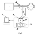
図1に示した、本発明の方法を実施するための測定システムは交流3相電源1に接続されており、当該交流3相電源1は給電ケーブル2によってモータ3に接続されている。同図の本発明の実施形態では交流電源1は3相であるが、図面には示していないものの、当業者であれば、本願にて開示した発明を、1相で給電される回転機にも、また多相で給電される回転機にも適用できることは明らかである。
DETAILED DESCRIPTION OF THE INVENTION The measurement system for carrying out the method of the present invention shown in FIG. 1 is connected to an AC three-
前記給電ケーブル2は測定装置4に接続されており、当該測定装置4はアナログデジタル変換器5を有する。このアナログデジタル変換器5はコンピュータ処理装置6に接続されており、当該コンピュータ処理装置6は、図中に示していない標準的な構成要素、たとえばプロセッサ、メモリおよび記憶モジュールを備えている。前記測定装置4はまた、本発明の方法を実施するのに適した処理モジュール7および無次元化モジュール8を備えている。コンピュータ処理装置6は測定装置4を通じて、本発明の方法を実施することにより得られる結果を可視化するための装置9に接続されている。図中の本発明の実施形態では測定装置4はコンピュータ装置6と統合されているが、測定装置とコンピュータ装置とを別体の装置とすることもできる。このことは図面には示していない。この場合には、前記結果を可視化する装置9はコンピュータ装置6に直接接続されているか、またはリモート接続されている。
The feeding cable 2 is connected to a measuring device 4, and the measuring device 4 has an analog /
図中に示した本発明の実施形態では、ステータ巻線に給電する交流電流のアナログ電流信号I1,I2,I3を測定するが、電気機械系の任意の電気的または機械的なアナログ波形の信号を記録することができ、たとえば、電圧信号、トルク信号、振動測定に関連する、たとえば変位、移動または加速度等の信号とすることもできる。ここで記載した方法は、任意の数の信号にそれぞれ別々に使用することができるので、以下の記載では、1つのアナログ波形信号の処理のみを取り上げる。このアナログ波形信号は、符号Sにより示している。本発明の方法は以下のステップ1〜5で実行される。 In the embodiment of the present invention shown in the figure, the analog current signals I1, I2 and I3 of the alternating current supplied to the stator windings are measured, but signals of any electrical or mechanical analog waveform of the electromechanical system are measured. Can be recorded, for example, a voltage signal, a torque signal, or a signal related to vibration measurement, such as displacement, movement or acceleration. Since the method described here can be used separately for any number of signals, only the processing of one analog waveform signal will be discussed in the following description. This analog waveform signal is indicated by symbol S. The method of the present invention is performed in the following steps 1-5.
ステップ1
ステップ1において測定アナログ波形信号Sを測定し、その後、測定アナログ波形信号Sをアナログデジタル変換器5において離散的信号SDに変換する。このアナログデジタル変換器5には定数パラメータP1が供給される。図2にアナログ信号Sと離散的電流信号SDとの双方を示しており、アナログ信号Sは実線で、離散的電流信号SDは丸印で示されている。パラメータP1はアナログ信号を離散的信号に変換する過程を表すものであり、ユーザにより設定されるサンプリングレートFSと、ユーザにより設定される、変換対象の信号の長さTLとにより構成されたものである。サンプリングレートFSは、アナログ波形信号Sから得られる毎秒サンプリング数である。通常、最小サンプリングレートは1kHzであり、これはデフォルト設定とされる。
In
信号長さTLは、アナログデジタル変換のために選択された、アナログ波形信号Sの長さである。本発明の方法のこの実施形態では、信号長さTLの最小値は1sである。 The signal length TL is the length of the analog waveform signal S selected for analog-digital conversion. In this embodiment of the method of the invention, the minimum value of the signal length TL is 1 s.
離散的信号SDは、コンピュータ装置6内に実装された処理モジュール7へ自動的に送信される。
The discrete signal SD is automatically transmitted to the
ステップ2
前記離散的信号SDは複数のサンプル{a1,・・・ai,・・・ak}により構成される。各サンプルは、時点、すなわち各サンプルが記録された時点と、アナログ波形信号Sから記録された、前記時点に対応する振幅との2つの座標により記述される。すべての時点のシーケンスにより、時点ベクトルが作成され、これらの時点に対応するすべての振幅のシーケンスにより、対応する振幅ベクトルが作成される。
Step 2
The discrete signal S D is a plurality of samples {a 1, ··· a i, ··· a k} formed by. Each sample is described by two coordinates: a time point, that is, a time point when each sample is recorded, and an amplitude corresponding to the time point recorded from the analog waveform signal S. A sequence of all points in time creates a point-in-time vector, and a sequence of all amplitudes corresponding to these points in time creates a corresponding amplitude vector.
ステップ2ではまず最初に、長さTLの離散的信号SDの数値の平均値Xmeanを、以下のようにして計算する:
Xmean = (a1 + a2 + ... ai ... +ak) / k (1)
ここで、aiはサンプルiの値であり、kは離散的信号SDに含まれるサンプルの総数である。サンプル数kは、サンプリング周波数FSに信号長さTLを乗算したものに等しい。
In step 2, first of all, the average value X mean of the numerical values of the discrete signal SD of length TL is calculated as follows:
X mean = (a 1 + a 2 + ... a i ... + a k ) / k (1)
Here, a i is the value of the sample i, and k is the total number of samples included in the discrete signal SD . The number of samples k is equal to the sampling frequency F S multiplied by the signal length T L.
次に、前記離散的信号SDの各サンプル点の値aiから前記平均値Xmeanを減算することにより、{b1,・・・bi・・・bk}により示したサンプルから構成される処理済み離散的信号SDPを計算する:
{bi} = {ai} - Xmean (2)
上述の演算の結果、処理済み離散的信号SDPの時点ベクトルは、信号SDの時点ベクトルと同じになり、かつ、処理済み離散的信号SDPの対応する振幅ベクトルは、信号SDの振幅ベクトルに対して変更されたものになる。
Next, configuration by subtracting the average value X mean from the values a i of each sample point of the discrete signal S D, the samples shown by {b 1, ··· b i ··· b k} Compute the processed discrete signal S DP to be:
{b i } = {a i }-X mean (2)
As a result of the above calculation, the time vector of the processed discrete signal S DP is the same as the time vector of the signal SD , and the corresponding amplitude vector of the processed discrete signal S DP is the amplitude of the signal SD . Changed to vector.
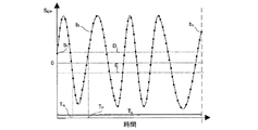
離散的信号SDの上述の変更は、次のゼロ交差の計算に必要なものである。図3に、時間領域における処理済み離散的信号SDPの各サンプルの値{b1,・・・bi,・・・bk}を示しており、同図から、処理済み離散的信号SDPの瞬時電源周波数を求めるプロセス中に特定される、当該処理済み離散的信号SDPの種々の特性が明らかである。ゼロ交差は、処理済み離散的信号SDPの符号の変化を検出することにより特定される。正のゼロ交差とは、処理済み離散的信号SDPの符号が負から正に変わるときに生じるゼロ交差として定義されるのに対し、負のゼロ交差とは、処理済み離散的信号SDPの符号が正から負に変わるときに生じるゼロ交差として定義される。 The above modification of the discrete signal SD is necessary for the next zero crossing calculation. FIG. 3 shows the values {b 1 ,... B i ,... B k } of each sample of the processed discrete signal S DP in the time domain. identified during the process of obtaining the instantaneous power frequency of DP, various properties of the processed discrete signal S DP is evident. Zero crossings are identified by detecting a change in the sign of the processed discrete signal SDP . A positive zero crossing is defined as a zero crossing that occurs when the sign of the processed discrete signal S DP changes from negative to positive, whereas a negative zero crossing is defined by the processed discrete signal S DP Defined as the zero crossing that occurs when the sign changes from positive to negative.
電源ケーブルにより収集される信号は常に、ある程度のレベルのノイズを含む。検出されるゼロ交差が、記録されたノイズに起因するものではなく、確実に、基礎となる電源信号の符号の変化に起因するものとなるようにするためには、P2で示しているように、正のヒステリシスパラメータDを供給する。有利には、ユーザにより与えられる正のヒステリシスパラメータDの値は、モータ定格電流の10%に等しくするべきである。処理済み離散的信号SDPの値が負から正に変わり、この値が正のヒステリシスパラメータDの値を上回る場合には、正のゼロ交差時点TPであると判定する。処理済み離散的信号SDPの値が正から負に変わり、この値が、ユーザにより設定された負のヒステリシスパラメータEを下回る場合には、負のゼロ交差時点TNになったと判定する。前記負のヒステリシスパラメータEは、正のヒステリシスの場合のP2として供給される正のヒステリシスパラメータDの値を負値にしたものである(E=−D)。連続した複数の正のゼロ交差時点TP1,TP2,・・・TPnのシーケンスと、連続した負のゼロ交差時点TN1,TN2,・・・TNnのシーケンスとが、このステップの結果となる。 The signal collected by the power cable always contains some level of noise. In order to ensure that the detected zero crossing is not due to recorded noise but due to a change in the sign of the underlying power signal, as indicated by P2. , Supply a positive hysteresis parameter D. Advantageously, the value of the positive hysteresis parameter D given by the user should be equal to 10% of the motor rated current. The value of the processed discrete signal S DP is positively changed from a negative, it is determined that if this value exceeds the value of the positive hysteresis parameter D is a positive zero crossing time T P. If the value of the processed discrete signal S DP changes from positive to negative and falls below the negative hysteresis parameter E set by the user, it is determined that the negative zero crossing time TN has been reached. The negative hysteresis parameter E is a value obtained by making the value of the positive hysteresis parameter D supplied as P2 in the case of positive hysteresis negative (E = −D). A sequence of a plurality of consecutive positive zero crossing points T P1 , T P2 ,... T Pn and a sequence of consecutive negative zero crossing points T N1 , T N2 ,. Result.
ステップ2にて説明した変換はすべて、処理モジュール7において実施される。
All the conversions described in step 2 are performed in the
ステップ3
ステップ3では、まず最初に、連続した各正のゼロ交差時点TP1,TP2,・・・TPnと連続した各負のゼロ交差時点TN1,TN2,・・・TNnとの間の時間間隔TD1,TD2,・・・TDnのシーケンスを、以下の数式にしたがって計算する:
TD1 = | TP1 - TN1|, TD2 = | TP2 - TN2|, ..., TDn = | TPn - TNn | (3)
次に、前記時間間隔TD1,TD2,・・・TDnのシーケンスの平均値の数値を、以下の数式のように計算する:
Tmean = (TD1 + TD2 + ... + TDn)/n (4)
ここで、nは正のゼロ交差または負のゼロ交差の総数である。
In
T D1 = | T P1 -T N1 |, T D2 = | T P2 -T N2 |, ..., T Dn = | T Pn -T Nn |
Next, the numerical value of the average value of the sequence of the time intervals T D1 , T D2 ,... T Dn is calculated as follows:
T mean = (T D1 + T D2 + ... + T Dn ) / n (4)
Here, n is the total number of positive zero crossings or negative zero crossings.
その次に、時間間隔のシーケンスの上記平均値の数値Tmeanに2を乗算したものの逆数を求めることにより、給電基本周波数Flを計算する:
Fl=1/2 Tmean (5)
次に、サンプリングレートFSを基本給電周波数Flにより除算することによって、給電基本周波数Flに等しい一定の周波数を有する信号の1期間NFsあたりのサンプル数を求める:
NFs=FS/Fl (6)
次に、連続した各正のゼロ交差時点TP1,TP2,・・・TPn間の分割個別周期SDP1,SDP2,・・・SDPnに、処理済み離散的信号SDPを分割する。各分割個別周期SDP1,SDP2,・・・SDPnの長さは時間領域において変化しうる。図4に、それぞれ異なる数のサンプルを有する、最初の2つの分割個別周期SDP1,SDP2を示している。分割個別周期SDP1は円により示しており、その次の分割個別周期SDP2は三角により示している。
Then, the feed fundamental frequency F l is calculated by finding the reciprocal of the average value T mean of the time interval sequence multiplied by 2:
F 1 = 1/2 T mean (5)
Next, the number of samples per period N Fs of a signal having a constant frequency equal to the feed fundamental frequency F 1 is determined by dividing the sampling rate F S by the fundamental feed frequency F 1 :
N Fs = F S / F l (6)
Then, the zero crossing point of each successive positive T P1, T P2, ··· T divided individual periods between Pn S DP1, S DP2, the · · · S DPn, divides the processed discrete signal S DP . The length of each divided individual period S DP1 , S DP2 ,... S DPn can vary in the time domain. FIG. 4 shows the first two divided individual periods S DP1 and S DP2 each having a different number of samples. The divided individual period S DP1 is indicated by a circle, and the next divided individual period S DP2 is indicated by a triangle.
次に、公知のリサンプリング技術を用いて各分割個別周期SDP1,SDP2,・・・SDPnをリサンプリングする。このリサンプリングは、リサンプリング後の分割個別周期SDR1,SDR2,・・・SDRnのサンプル数が、給電基本周波数Flに等しい一定の周波数を有する信号の1期間NFsにおけるサンプル数と同数になるように行われる。図5に、サンプル数が同数である、リサンプリング後の最初の2つの個別周期SDR1およびSDR2を示す。 Next, each divided individual period S DP1 , S DP2 ,... S DPn is resampled using a known resampling technique. This resampling is divided individual cycle S DR1, S DR2 after resampling, the number of samples · · · S DRn is, the number of samples in one period N Fs signal having a constant frequency equal to the power supply base frequency F l It is done so that it becomes the same number. FIG. 5 shows the first two individual periods SDR1 and SDR2 after resampling with the same number of samples.
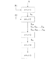
次に、時点ベクトルの置換を行う。リサンプリング後の各分割個別周期SDR1,SDR2,・・・SDRnはそれぞれ、時点ベクトルと、これに対応する振幅ベクトルとを含む。分割個別周期SDR1では、時点ベクトルを連続した整数のベクトルに置換し、その結果は、連続した整数のベクトルと、これに対応する振幅ベクトルとを含む新たな無次元の個別周期SDN1となる。この演算は、サンプリング後の各分割個別周期SDR2,・・・SDRnに対しても、SDN1と同様に繰り返し行う。図6に、サンプル数が同数である最初の2つの無次元分割個別周期SDN1およびSDN2を示す。信号SDN1は丸印により示されており、信号SDN2は三角形印により示されている。 Next, time point vector replacement is performed. Each divided individual period S DR1 , S DR2 ,... S DRn after resampling includes a time point vector and an amplitude vector corresponding thereto. In the divided individual period SDR1 , the time point vector is replaced with a continuous integer vector, and the result is a new dimensionless individual period SDN1 including a continuous integer vector and a corresponding amplitude vector. . This calculation is repeated for each divided individual period S DR2 ,... S DRn after sampling in the same manner as S DN1 . FIG. 6 shows the first two dimensionless divided individual periods S DN1 and S DN2 having the same number of samples. The signal S DN1 is indicated by a circle, and the signal S DN2 is indicated by a triangle.
次に、分割後の無次元信号SDN1,SDN2,・・・SDNnをすべて連結して、連続した分割後の無次元信号からサンプルを取り出して順次並べる。このように連結すると、複数の整数のベクトルと、これに対応する振幅ベクトルとを含む無次元の離散的信号SNが形成される。この無次元信号SNは図7に示されている。 Next, the divided dimensionless signals S DN1 , S DN2 ,... S DNn are all connected, and samples are extracted from the consecutive dimensionless signals after being divided and sequentially arranged. When connected in this way, a dimensionless discrete signal S N including a plurality of integer vectors and corresponding amplitude vectors is formed. This dimensionless signal SN is shown in FIG.
次に、整数の前記ベクトルの連続した複数の要素を、昇順の時点のベクトルに置換する。この置換では、各昇順時点間の期間がサンプリングレートFSの逆数に等しくなるようにする。このステップの結果、変更された時点ベクトルと、これに対応する振幅ベクトルとを含む有次元の定常信号SNtが形成される。この有次元定常信号SNtは図8に示されている。 Next, a plurality of consecutive elements of the integer vector are replaced with ascending time vectors. In this replacement, the period between each ascending time point is set equal to the reciprocal of the sampling rate F S. As a result of this step, a dimensional steady signal S Nt including the changed time point vector and the corresponding amplitude vector is formed. This dimensionally steady signal S Nt is shown in FIG.
ステップS3にて説明した変換はすべて、コンピュータ装置6に実装された無次元化モジュール8において実施される。 All the conversions described in step S3 are performed in the dimensionless module 8 installed in the computer device 6.
ステップ4
次に、有次元定常信号SNtのDFT(Discrete Fourier Transform)の計算を行う。このDFT演算は、スペクトル解析を行えるように、信号を時間領域から周波数領域の信号に変換するものである。たとえば高速フーリエ変換等の、DFTを計算するために用いられるアルゴリズムを含めたこの計算の詳細は、当業者に周知である。
Step 4
Next, the DFT (Discrete Fourier Transform) of the dimensional steady signal SNt is calculated. This DFT operation converts a signal from a time domain signal to a frequency domain signal so that spectrum analysis can be performed. Details of this calculation, including the algorithms used to calculate the DFT, such as the fast Fourier transform, are well known to those skilled in the art.
対象となる周波数のベクトルと、これに対応する振幅ベクトルとを抽出するためには、上述のようにして得られたDFTスペクトラムを任意の公知の手法によって処理することができる。 In order to extract the frequency vector of interest and the corresponding amplitude vector, the DFT spectrum obtained as described above can be processed by any known method.
対象となる周波数のベクトルと、これに対応する振幅ベクトルとを用いて、電気機械系の診断を行うことができる。上述のベクトルから得られるデータは特に、公知の電流徴候解析‐MCSAを行うのに用いることができる。 The electromechanical system can be diagnosed using the frequency vector of interest and the corresponding amplitude vector. The data obtained from the vectors described above can be used in particular for performing known current symptom analysis-MCSA.
ステップ5
ステップ5では、公知の手法を用いる可視化装置9を用いて、ステップ4にて得られた結果を表示する。
In
符号 呼称
S アナログ波形信号
P1 定数パラメータ
FS サンプリングレート
TL 信号の長さ
SD 離散的信号
a1,・・・ai,・・・ak 離散的信号SDのサンプル
k 離散的信号に含まれるサンプル総数
Xmean 離散的信号の平均値の数値
SDP 処理済みの離散的信号
b1,・・・bi,・・・bk 処理済みの離散的信号SDPのサンプル
D 正のヒステリシスパラメータ
E 負のヒステリシスパラメータ
P2 定数パラメータ
TP 正のゼロ交差時点
TN 負のゼロ交差時点
TP1,TP2,・・・TPn 連続した正のゼロ交差時点のシーケンス
TN1,TN2,・・・TNn 連続した負のゼロ交差時点のシーケンス
TD1,TD2,・・・TDn 時間間隔のシーケンス
Tmean 前記時間間隔シーケンスの平均値の数値
Fl 給電基本周波数
NFs 前記給電基本周波数に等しい一定の周波数を有する信号の1周期あたりのサンプル数
SDP1,SDP2,・・・SDPn 信号SDPの分割個別周期
SDR1,SDR2,・・・SDRn リサンプリング後の分割個別周期
SDN1,SDN2,・・・SDNn 無次元の分割個別周期
SN 無次元化された離散的信号
SNt 有次元化された定常信号
Symbol Name S Analog waveform signal P1 Constant parameter F S Sampling rate T L Signal length S D Discrete signal a 1 ,... A i ,... A k Discrete signal SD Sample k Discrete signal Total number of samples included X mean A numerical value of the mean value of the discrete signal S DP processed discrete signal b 1 ,... B i ,... B k processed discrete signal S DP sample D Positive hysteresis Parameter E Negative hysteresis parameter P2 Constant parameter TP Positive zero crossing point T N Negative zero crossing point T P1 , T P2 ,... T Pn Continuous positive zero crossing point sequence T N1 , T N2,. ..T Nn consecutive negative zero crossing time sequence T D1 , T D2 ,... T Dn time interval sequence T mean the time interval sequence F l Feed basic frequency N Fs Number of samples per cycle of a signal having a constant frequency equal to the feed fundamental frequency S DP1 , S DP2 ,... S DPn Signal S DP divided individual cycle S DR 1 , S DR 2 ,... S DRn Divided individual period after resampling S DN 1 , S DN 2 ,... S DNn Non-dimensional divided individual period S N Non-dimensionalized discrete signal S Nt Stationary signal
Claims (7)
・前記電気機械系のアナログの波形信号(S)を測定するステップと、
・測定した前記波形信号(S)を、
時点のベクトルと、
対応する振幅ベクトルと
を含む処理済み離散的信号(SDP)に変換するステップと、
・前記処理済み離散的信号(SDP)を、複数の分割個別周期(SDP1,SDP2・・・SDPn)に分割するステップと
を有し、ただし前記各分割個別周期は、他の分割個別周期のサンプル数と同数または異なる数のサンプルを有し、
前記方法はさらに、
・リサンプリング後の分割個別周期(SDR1,SDR2・・・SDRn)を得るためのリサンプリング手順によって、前記各分割個別周期(SDP1,SDP2・・・SDPn)のサンプル数を変更するステップ
を有し、ただし当該サンプル数を変更するステップは、前記リサンプリング後の各分割個別周期に含まれるサンプル数がすべて等しくなるように行い、
前記方法はさらに、
・前記リサンプリング後の各個別周期(SDR1,SDR2・・・SDRn)ごとの時点のベクトルを連続した整数のベクトルに置換して、無次元の分割個別周期(SDN1,SDN2・・・SDNn)を得るステップと、
・前記連続した無次元の分割個別周期からサンプルを順次並べて、複数の連続したサンプルのシーケンスを形成することにより、すべての前記無次元の分割個別周期(SDN1,SDN2・・・SDNn)を連結して1つの無次元離散的信号(SN)にまとめるステップと、
・前記無次元離散的信号(SN)における昇順の時点のベクトルに、前記連続した整数のベクトルを置換することにより、有次元化された定常信号(SNt)を得るステップと、
・前記有次元化された定常信号(SNt)を時間領域から周波数領域に変換することにより、対象となる周波数ベクトルと、これに対応する振幅ベクトルとを抽出する元になる周波数スペクトルを求めるステップと
を有し、
ただし、前記周波数ベクトルおよび振幅ベクトルは、前記電気機械系の診断に用いられ、可視化装置上で表示されるものである
ことを特徴とする方法。 A method for obtaining a stationary signal for diagnosing an electromechanical system,
Measuring the analog waveform signal (S) of the electromechanical system;
The measured waveform signal (S) is
A vector of points in time,
Converting to a processed discrete signal (S DP ) comprising a corresponding amplitude vector;
Dividing the processed discrete signal (S DP ) into a plurality of divided individual periods (S DP1 , S DP2 ... S DPn ), wherein each divided individual period is another divided period. Have the same or different number of samples as the number of samples in the individual period,
The method further includes:
· The resampling procedure for obtaining divided individual cycle of the re-sampled (S DR1, S DR2 ··· S DRn), wherein the number of samples in each divided individual period (S DP1, S DP2 ··· S DPn) A step of changing the number of samples, but the step of changing the number of samples is performed so that the number of samples included in each divided individual period after the resampling is all equal,
The method further includes:
A vector at a point in time for each individual period (S DR1 , S DR2 ... S DRn ) after the re-sampling is replaced with a continuous integer vector, and dimensionless individual periods (S DN1 , S DN2 .. Obtaining S DNn ),
All the dimensionless divided individual periods (S DN1 , S DN2 ... S DNn ) by sequentially arranging samples from the continuous dimensionless divided individual periods to form a sequence of a plurality of consecutive samples. Concatenating them into one dimensionless discrete signal (S N );
Obtaining a dimensionalized stationary signal (S Nt ) by substituting the continuous integer vector for a vector in ascending order in the dimensionless discrete signal (S N );
A step of obtaining a frequency spectrum from which a target frequency vector and an amplitude vector corresponding to the target frequency vector are extracted by converting the dimensionalized steady signal (S Nt ) from the time domain to the frequency domain. And
However, the frequency vector and the amplitude vector are used for diagnosis of the electromechanical system and are displayed on a visualization device.
請求項1記載の方法。 The analog signal to be measured is a current signal,
The method of claim 1.
請求項2記載の方法。 The method of diagnosing the electromechanical system is current sign analysis,
The method of claim 2.
請求項1記載の方法。 The analog signal to be measured is a voltage signal,
The method of claim 1.
請求項1記載の方法。 The analog signal to be measured is a torque signal,
The method of claim 1.
請求項1記載の方法。 The analog signal to be measured is acceleration, velocity, or oscillating motion,
The method of claim 1.
・前記電気機械系のアナログの波形信号(S)を測定し、・ Measure the analog waveform signal (S) of the electromechanical system,
・測定した前記波形信号(S)を、The measured waveform signal (S) is
時点のベクトルと、A vector of points in time,
対応する振幅ベクトルとWith the corresponding amplitude vector
を含む処理済み離散的信号(SProcessed discrete signal (S DPDP )に変換し、)
・前記処理済み離散的信号(SThe processed discrete signal (S DPDP )を、複数の分割個別周期(S) Is divided into a plurality of divided individual periods (S DP1DP1 ,S, S DP2DP2 ・・・S... S DPnDPn )に分割し、)
ただし前記各分割個別周期は、他の分割個別周期のサンプル数と同数または異なる数のサンプルを有し、However, each of the divided individual periods has the same or different number of samples as the number of samples of the other divided individual periods,
前記装置はさらに、The apparatus further includes:
・リサンプリング後の分割個別周期(S-Divided individual period after resampling (S DR1DR1 ,S, S DR2DR2 ・・・S... S DRnDRn )を得るためのリサンプリング手順によって、前記各分割個別周期(S) To obtain the respective divided individual periods (S DP1DP1 ,S, S DP2DP2 ・・・S... S DPnDPn )のサンプル数を変更し、) Change the number of samples
ただし当該サンプル数を変更する際に、前記リサンプリング後の各分割個別周期に含まれるサンプル数がすべて等しくなるようにし、However, when changing the number of samples, the number of samples included in each divided individual period after the resampling is all equal,
前記装置はさらに、The apparatus further includes:
・前記リサンプリング後の各個別周期(S・ Each individual cycle (S DR1DR1 ,S, S DR2DR2 ・・・S... S DRnDRn )ごとの時点のベクトルを連続した整数のベクトルに置換して、無次元の分割個別周期(S) Is replaced with a vector of consecutive integers, and a dimensionless divided individual period (S DN1DN1 ,S, S DN2DN2 ・・・S... S DNnDNn )を取得し、)
・前記連続した無次元の分割個別周期からサンプルを順次並べて、複数の連続したサンプルのシーケンスを形成することにより、すべての前記無次元の分割個別周期(SBy sequentially arranging samples from the continuous dimensionless divided individual periods to form a sequence of a plurality of consecutive samples, all the dimensionless divided individual periods (S DN1DN1 ,S, S DN2DN2 ・・・S... S DNnDNn )を連結して1つの無次元離散的信号(S) To form a single dimensionless discrete signal (S NN )にまとめ、)
・前記無次元離散的信号(SThe dimensionless discrete signal (S NN )における昇順の時点のベクトルに、前記連続した整数のベクトルを置換することにより、有次元化された定常信号(S) By replacing the continuous vector of integers with the vectors in ascending order in FIG. NtNt )を取得し、)
・前記有次元化された定常信号(S-The dimensionalized steady signal (S NtNt )を時間領域から周波数領域に変換することにより、対象となる周波数ベクトルと、これに対応する振幅ベクトルとを抽出する元になる周波数スペクトルを求める、) From the time domain to the frequency domain to obtain a frequency spectrum from which the target frequency vector and the corresponding amplitude vector are extracted.
ただし、前記周波数ベクトルおよび振幅ベクトルは、前記電気機械系の診断に用いられ、可視化装置上で表示されるものであるHowever, the frequency vector and the amplitude vector are used for diagnosis of the electromechanical system and are displayed on the visualization device.
ことを特徴とする装置。A device characterized by that.
Applications Claiming Priority (3)
| Application Number | Priority Date | Filing Date | Title |
|---|---|---|---|
| EP11460050A EP2574947A1 (en) | 2011-09-30 | 2011-09-30 | A method of determining stationary signals for the diagnostics of an electromechanical system |
| EP11460050.5 | 2011-09-30 | ||
| PCT/EP2012/003915 WO2013045045A1 (en) | 2011-09-30 | 2012-09-19 | A method of determining stationary signals for the diagnostics of an electromechanical system |
Publications (3)
| Publication Number | Publication Date |
|---|---|
| JP2014531593A JP2014531593A (en) | 2014-11-27 |
| JP2014531593A5 JP2014531593A5 (en) | 2015-11-05 |
| JP6000360B2 true JP6000360B2 (en) | 2016-09-28 |
Family
ID=46982510
Family Applications (1)
| Application Number | Title | Priority Date | Filing Date |
|---|---|---|---|
| JP2014532263A Active JP6000360B2 (en) | 2011-09-30 | 2012-09-19 | Method and apparatus for obtaining a stationary signal for diagnosing an electromechanical system |
Country Status (11)
| Country | Link |
|---|---|
| US (1) | US9869720B2 (en) |
| EP (2) | EP2574947A1 (en) |
| JP (1) | JP6000360B2 (en) |
| KR (1) | KR101946668B1 (en) |
| CN (1) | CN103827683B (en) |
| AU (1) | AU2012314960B2 (en) |
| BR (1) | BR112014007556B1 (en) |
| CA (1) | CA2849549C (en) |
| DK (1) | DK2761315T3 (en) |
| IN (1) | IN2014CN03052A (en) |
| WO (1) | WO2013045045A1 (en) |
Cited By (1)
| Publication number | Priority date | Publication date | Assignee | Title |
|---|---|---|---|---|
| US10175274B2 (en) | 2017-03-21 | 2019-01-08 | Lsis Co., Ltd. | Device for detecting output current of inverter |
Families Citing this family (7)
| Publication number | Priority date | Publication date | Assignee | Title |
|---|---|---|---|---|
| ES2534412T3 (en) * | 2012-10-26 | 2015-04-22 | Abb Technology Ag | A method for the diagnosis of an electromechanical system based on impedance analysis |
| CN104062585B (en) * | 2014-06-16 | 2016-09-28 | 北京控制工程研究所 | A kind of reliability verification method of hemisphere bearing dynamic pressure motor |
| EP2988187B1 (en) * | 2014-08-22 | 2017-03-29 | ABB Schweiz AG | A method for assessing the condition of rotating machinery connected to an electric motor |
| US10928814B2 (en) | 2017-02-24 | 2021-02-23 | General Electric Technology Gmbh | Autonomous procedure for monitoring and diagnostics of machine based on electrical signature analysis |
| US10403116B2 (en) | 2017-06-20 | 2019-09-03 | General Electric Company | Electrical signature analysis of electrical rotating machines |
| US20210062803A1 (en) * | 2018-01-24 | 2021-03-04 | Magnetic Pumping Solutions Llc | Method and system for monitoring the condition of rotating systems |
| CN116597167B (en) * | 2023-06-06 | 2024-02-27 | 中国人民解放军92942部队 | Permanent magnet synchronous motor small sample demagnetization fault diagnosis method, storage medium and system |
Family Cites Families (15)
| Publication number | Priority date | Publication date | Assignee | Title |
|---|---|---|---|---|
| US5461329A (en) | 1992-01-21 | 1995-10-24 | Martin Marietta Energy Systems, Inc. | Method and apparatus for generating motor current spectra to enhance motor system fault detection |
| SE521013C2 (en) * | 1997-09-30 | 2003-09-23 | Abb Ab | Rotary electric machine with winding made of high voltage cable |
| US6026348A (en) * | 1997-10-14 | 2000-02-15 | Bently Nevada Corporation | Apparatus and method for compressing measurement data correlative to machine status |
| US6321602B1 (en) * | 1999-09-28 | 2001-11-27 | Rockwell Science Center, Llc | Condition based monitoring by vibrational analysis |
| FI20000646A0 (en) * | 2000-03-20 | 2000-03-20 | Abb Research Ltd | Method for determining the speed of rotation |
| FI20000647A0 (en) * | 2000-03-20 | 2000-03-20 | Abb Research Ltd | Method for determining the speed of a short-circuited motor |
| CN1945349B (en) * | 2006-10-30 | 2010-10-06 | 天津理工大学 | Flexible generating device for embedded AC motor complex fault |
| CN101025430A (en) * | 2007-03-28 | 2007-08-29 | 华北电力大学 | Cage type asynchronous motor rotor strip-broken failure detecting method |
| DE102008025596B4 (en) * | 2008-05-28 | 2020-06-10 | Robert Bosch Gmbh | Procedure for operating a facility |
| CN101329374A (en) * | 2008-06-13 | 2008-12-24 | 哈尔滨工业大学 | Computation method of differential filter weighting period small amplitude value |
| FI20080438A0 (en) * | 2008-07-15 | 2008-07-15 | Abb Oy | Method and apparatus for measuring bearing currents in an electric machine |
| EP2270522B1 (en) * | 2009-07-03 | 2012-05-30 | ABB Oy | Induction motor parameter identification |
| EP2357483B1 (en) * | 2010-02-17 | 2013-06-26 | ABB Research Ltd. | A method of subsynchronous resonance detection |
| EP2426502A1 (en) * | 2010-09-06 | 2012-03-07 | ABB Technology AG | A method for detecting rotor failure in an asynchronous motor |
| EP2523009B1 (en) * | 2011-05-12 | 2015-01-28 | ABB Technology AG | Method and apparatus for monitoring the condition of electromechanical systems |
-
2011
- 2011-09-30 EP EP11460050A patent/EP2574947A1/en not_active Withdrawn
-
2012
- 2012-09-19 CN CN201280047722.1A patent/CN103827683B/en active Active
- 2012-09-19 CA CA2849549A patent/CA2849549C/en active Active
- 2012-09-19 BR BR112014007556-5A patent/BR112014007556B1/en active IP Right Grant
- 2012-09-19 JP JP2014532263A patent/JP6000360B2/en active Active
- 2012-09-19 WO PCT/EP2012/003915 patent/WO2013045045A1/en active Application Filing
- 2012-09-19 IN IN3052CHN2014 patent/IN2014CN03052A/en unknown
- 2012-09-19 AU AU2012314960A patent/AU2012314960B2/en active Active
- 2012-09-19 EP EP12769321.6A patent/EP2761315B1/en active Active
- 2012-09-19 DK DK12769321.6T patent/DK2761315T3/en active
- 2012-09-19 US US14/348,083 patent/US9869720B2/en active Active
- 2012-09-19 KR KR1020147009187A patent/KR101946668B1/en active IP Right Grant
Cited By (1)
| Publication number | Priority date | Publication date | Assignee | Title |
|---|---|---|---|---|
| US10175274B2 (en) | 2017-03-21 | 2019-01-08 | Lsis Co., Ltd. | Device for detecting output current of inverter |
Also Published As
| Publication number | Publication date |
|---|---|
| EP2761315B1 (en) | 2015-08-26 |
| AU2012314960B2 (en) | 2017-01-05 |
| CN103827683A (en) | 2014-05-28 |
| EP2574947A1 (en) | 2013-04-03 |
| IN2014CN03052A (en) | 2015-07-03 |
| CA2849549C (en) | 2021-02-16 |
| BR112014007556B1 (en) | 2021-01-26 |
| BR112014007556A2 (en) | 2017-04-04 |
| EP2761315A1 (en) | 2014-08-06 |
| WO2013045045A1 (en) | 2013-04-04 |
| KR20140068164A (en) | 2014-06-05 |
| CN103827683B (en) | 2017-09-12 |
| DK2761315T3 (en) | 2015-12-07 |
| US9869720B2 (en) | 2018-01-16 |
| US20140236537A1 (en) | 2014-08-21 |
| AU2012314960A1 (en) | 2014-05-01 |
| JP2014531593A (en) | 2014-11-27 |
| KR101946668B1 (en) | 2019-02-11 |
| CA2849549A1 (en) | 2013-04-04 |
Similar Documents
| Publication | Publication Date | Title |
|---|---|---|
| JP6000360B2 (en) | Method and apparatus for obtaining a stationary signal for diagnosing an electromechanical system | |
| JP5932022B2 (en) | Method and apparatus for monitoring the state of an electromechanical system | |
| JP6223461B2 (en) | Diagnosis method of electromechanical system based on impedance analysis | |
| Su et al. | Induction machine condition monitoring using neural network modeling | |
| DK2565658T3 (en) | Fault detection based on current signature analysis of a generator | |
| JP6945371B2 (en) | Diagnostic equipment for rotating machine systems, power converters, rotating machine systems, and diagnostic methods for rotating machine systems. | |
| Corne et al. | Comparing MCSA with vibration analysis in order to detect bearing faults—A case study | |
| CN103116032A (en) | Method and device for acquiring rotating speed of wind generating set | |
| Chang et al. | On-line motor condition monitoring system for abnormality detection | |
| JP2012154844A5 (en) | ||
| Roque et al. | Sensorless speed estimation for inductions motors using slot harmonics and time-based frequency estimation | |
| Alekseev et al. | Data measurement system of compressor units defect diagnosis by vibration value | |
| JP2018059848A (en) | Rotary machine diagnosis system and data processing method thereof | |
| Nandi | Fault Diagnosis of Electric Machines Using Techniques Based on Frequency Domain | |
| Klein-Hessling et al. | Acoustic optimization using vibration sensor feedback to the controller | |
| JP5992942B2 (en) | Abnormal state detection method and apparatus for driving an AC motor | |
| CHANDRALEKHA et al. | IMPLEMENTATION OF PICCOLO DSP BASED FAULT MONITORING SYSTEM FOR SINGLE PHASE INDUCTION MOTOR | |
| Payne et al. | Componential coding in the condition monitoring of electrical machines Part 2: application to a conventional machine and a novel machine | |
| Wei et al. | Broken rotor bar detection in induction motors via wavelet ridge |
Legal Events
| Date | Code | Title | Description |
|---|---|---|---|
| A521 | Request for written amendment filed |
Free format text: JAPANESE INTERMEDIATE CODE: A523 Effective date: 20150914 |
|
| A621 | Written request for application examination |
Free format text: JAPANESE INTERMEDIATE CODE: A621 Effective date: 20150914 |
|
| A977 | Report on retrieval |
Free format text: JAPANESE INTERMEDIATE CODE: A971007 Effective date: 20160725 |
|
| TRDD | Decision of grant or rejection written | ||
| A01 | Written decision to grant a patent or to grant a registration (utility model) |
Free format text: JAPANESE INTERMEDIATE CODE: A01 Effective date: 20160801 |
|
| A61 | First payment of annual fees (during grant procedure) |
Free format text: JAPANESE INTERMEDIATE CODE: A61 Effective date: 20160830 |
|
| R150 | Certificate of patent or registration of utility model |
Ref document number: 6000360 Country of ref document: JP Free format text: JAPANESE INTERMEDIATE CODE: R150 |
|
| S111 | Request for change of ownership or part of ownership |
Free format text: JAPANESE INTERMEDIATE CODE: R313111 |
|
| R350 | Written notification of registration of transfer |
Free format text: JAPANESE INTERMEDIATE CODE: R350 |
|
| R250 | Receipt of annual fees |
Free format text: JAPANESE INTERMEDIATE CODE: R250 |
|
| R250 | Receipt of annual fees |
Free format text: JAPANESE INTERMEDIATE CODE: R250 |
|
| R250 | Receipt of annual fees |
Free format text: JAPANESE INTERMEDIATE CODE: R250 |
|
| R250 | Receipt of annual fees |
Free format text: JAPANESE INTERMEDIATE CODE: R250 |
|
| R250 | Receipt of annual fees |
Free format text: JAPANESE INTERMEDIATE CODE: R250 |