JP6000331B2 - An apparatus and method for producing a fiber preform, which is a preform in particular for producing a fiber-reinforced plastic member - Google Patents
An apparatus and method for producing a fiber preform, which is a preform in particular for producing a fiber-reinforced plastic member Download PDFInfo
- Publication number
- JP6000331B2 JP6000331B2 JP2014503037A JP2014503037A JP6000331B2 JP 6000331 B2 JP6000331 B2 JP 6000331B2 JP 2014503037 A JP2014503037 A JP 2014503037A JP 2014503037 A JP2014503037 A JP 2014503037A JP 6000331 B2 JP6000331 B2 JP 6000331B2
- Authority
- JP
- Japan
- Prior art keywords
- yarn
- mold
- roving
- tension
- gripper
- Prior art date
- Legal status (The legal status is an assumption and is not a legal conclusion. Google has not performed a legal analysis and makes no representation as to the accuracy of the status listed.)
- Expired - Fee Related
Links
- 239000000835 fiber Substances 0.000 title claims description 52
- 229920002430 Fibre-reinforced plastic Polymers 0.000 title claims description 9
- 239000011151 fibre-reinforced plastic Substances 0.000 title claims description 9
- 238000004519 manufacturing process Methods 0.000 title description 15
- 238000007493 shaping process Methods 0.000 claims description 59
- 238000000034 method Methods 0.000 claims description 32
- 239000000463 material Substances 0.000 claims description 23
- 238000005520 cutting process Methods 0.000 claims description 13
- 239000007787 solid Substances 0.000 claims description 12
- 238000010438 heat treatment Methods 0.000 claims description 6
- 238000003825 pressing Methods 0.000 claims description 5
- 238000002360 preparation method Methods 0.000 claims description 4
- 230000006978 adaptation Effects 0.000 claims description 3
- 230000001105 regulatory effect Effects 0.000 claims 1
- 238000007665 sagging Methods 0.000 claims 1
- 239000002657 fibrous material Substances 0.000 description 10
- 238000000465 moulding Methods 0.000 description 10
- 239000011265 semifinished product Substances 0.000 description 10
- 238000003892 spreading Methods 0.000 description 5
- 239000011159 matrix material Substances 0.000 description 4
- 239000000853 adhesive Substances 0.000 description 3
- 230000001070 adhesive effect Effects 0.000 description 3
- 239000011230 binding agent Substances 0.000 description 3
- 229920001169 thermoplastic Polymers 0.000 description 3
- 239000004416 thermosoftening plastic Substances 0.000 description 3
- 210000000078 claw Anatomy 0.000 description 2
- 238000010276 construction Methods 0.000 description 2
- 230000001419 dependent effect Effects 0.000 description 2
- 229920005989 resin Polymers 0.000 description 2
- 239000011347 resin Substances 0.000 description 2
- 238000005507 spraying Methods 0.000 description 2
- OKTJSMMVPCPJKN-UHFFFAOYSA-N Carbon Chemical compound [C] OKTJSMMVPCPJKN-UHFFFAOYSA-N 0.000 description 1
- 230000003213 activating effect Effects 0.000 description 1
- 230000004913 activation Effects 0.000 description 1
- 238000004026 adhesive bonding Methods 0.000 description 1
- 239000004760 aramid Substances 0.000 description 1
- 229920003235 aromatic polyamide Polymers 0.000 description 1
- 238000009727 automated fiber placement Methods 0.000 description 1
- 230000015572 biosynthetic process Effects 0.000 description 1
- 229910052799 carbon Inorganic materials 0.000 description 1
- 239000011248 coating agent Substances 0.000 description 1
- 238000000576 coating method Methods 0.000 description 1
- 238000001816 cooling Methods 0.000 description 1
- 238000002788 crimping Methods 0.000 description 1
- 238000006073 displacement reaction Methods 0.000 description 1
- 238000001035 drying Methods 0.000 description 1
- 239000003822 epoxy resin Substances 0.000 description 1
- -1 for example Polymers 0.000 description 1
- 239000011521 glass Substances 0.000 description 1
- LNEPOXFFQSENCJ-UHFFFAOYSA-N haloperidol Chemical compound C1CC(O)(C=2C=CC(Cl)=CC=2)CCN1CCCC(=O)C1=CC=C(F)C=C1 LNEPOXFFQSENCJ-UHFFFAOYSA-N 0.000 description 1
- 238000005470 impregnation Methods 0.000 description 1
- 238000005304 joining Methods 0.000 description 1
- 238000010030 laminating Methods 0.000 description 1
- 238000005259 measurement Methods 0.000 description 1
- 239000004033 plastic Substances 0.000 description 1
- 229920003023 plastic Polymers 0.000 description 1
- 229920000647 polyepoxide Polymers 0.000 description 1
- 229920000642 polymer Polymers 0.000 description 1
- 229920001187 thermosetting polymer Polymers 0.000 description 1
- 238000004804 winding Methods 0.000 description 1
- 239000002759 woven fabric Substances 0.000 description 1
- 230000037303 wrinkles Effects 0.000 description 1
Images


Classifications
-
- B—PERFORMING OPERATIONS; TRANSPORTING
- B29—WORKING OF PLASTICS; WORKING OF SUBSTANCES IN A PLASTIC STATE IN GENERAL
- B29C—SHAPING OR JOINING OF PLASTICS; SHAPING OF MATERIAL IN A PLASTIC STATE, NOT OTHERWISE PROVIDED FOR; AFTER-TREATMENT OF THE SHAPED PRODUCTS, e.g. REPAIRING
- B29C70/00—Shaping composites, i.e. plastics material comprising reinforcements, fillers or preformed parts, e.g. inserts
- B29C70/02—Shaping composites, i.e. plastics material comprising reinforcements, fillers or preformed parts, e.g. inserts comprising combinations of reinforcements, e.g. non-specified reinforcements, fibrous reinforcing inserts and fillers, e.g. particulate fillers, incorporated in matrix material, forming one or more layers and with or without non-reinforced or non-filled layers
-
- B—PERFORMING OPERATIONS; TRANSPORTING
- B29—WORKING OF PLASTICS; WORKING OF SUBSTANCES IN A PLASTIC STATE IN GENERAL
- B29B—PREPARATION OR PRETREATMENT OF THE MATERIAL TO BE SHAPED; MAKING GRANULES OR PREFORMS; RECOVERY OF PLASTICS OR OTHER CONSTITUENTS OF WASTE MATERIAL CONTAINING PLASTICS
- B29B11/00—Making preforms
- B29B11/14—Making preforms characterised by structure or composition
- B29B11/16—Making preforms characterised by structure or composition comprising fillers or reinforcement
-
- B—PERFORMING OPERATIONS; TRANSPORTING
- B29—WORKING OF PLASTICS; WORKING OF SUBSTANCES IN A PLASTIC STATE IN GENERAL
- B29C—SHAPING OR JOINING OF PLASTICS; SHAPING OF MATERIAL IN A PLASTIC STATE, NOT OTHERWISE PROVIDED FOR; AFTER-TREATMENT OF THE SHAPED PRODUCTS, e.g. REPAIRING
- B29C70/00—Shaping composites, i.e. plastics material comprising reinforcements, fillers or preformed parts, e.g. inserts
- B29C70/04—Shaping composites, i.e. plastics material comprising reinforcements, fillers or preformed parts, e.g. inserts comprising reinforcements only, e.g. self-reinforcing plastics
- B29C70/28—Shaping operations therefor
- B29C70/30—Shaping by lay-up, i.e. applying fibres, tape or broadsheet on a mould, former or core; Shaping by spray-up, i.e. spraying of fibres on a mould, former or core
- B29C70/38—Automated lay-up, e.g. using robots, laying filaments according to predetermined patterns
- B29C70/382—Automated fiber placement [AFP]
-
- B—PERFORMING OPERATIONS; TRANSPORTING
- B29—WORKING OF PLASTICS; WORKING OF SUBSTANCES IN A PLASTIC STATE IN GENERAL
- B29C—SHAPING OR JOINING OF PLASTICS; SHAPING OF MATERIAL IN A PLASTIC STATE, NOT OTHERWISE PROVIDED FOR; AFTER-TREATMENT OF THE SHAPED PRODUCTS, e.g. REPAIRING
- B29C70/00—Shaping composites, i.e. plastics material comprising reinforcements, fillers or preformed parts, e.g. inserts
- B29C70/04—Shaping composites, i.e. plastics material comprising reinforcements, fillers or preformed parts, e.g. inserts comprising reinforcements only, e.g. self-reinforcing plastics
- B29C70/28—Shaping operations therefor
- B29C70/54—Component parts, details or accessories; Auxiliary operations, e.g. feeding or storage of prepregs or SMC after impregnation or during ageing
- B29C70/541—Positioning reinforcements in a mould, e.g. using clamping means for the reinforcement
-
- B—PERFORMING OPERATIONS; TRANSPORTING
- B29—WORKING OF PLASTICS; WORKING OF SUBSTANCES IN A PLASTIC STATE IN GENERAL
- B29C—SHAPING OR JOINING OF PLASTICS; SHAPING OF MATERIAL IN A PLASTIC STATE, NOT OTHERWISE PROVIDED FOR; AFTER-TREATMENT OF THE SHAPED PRODUCTS, e.g. REPAIRING
- B29C70/00—Shaping composites, i.e. plastics material comprising reinforcements, fillers or preformed parts, e.g. inserts
- B29C70/04—Shaping composites, i.e. plastics material comprising reinforcements, fillers or preformed parts, e.g. inserts comprising reinforcements only, e.g. self-reinforcing plastics
- B29C70/28—Shaping operations therefor
- B29C70/54—Component parts, details or accessories; Auxiliary operations, e.g. feeding or storage of prepregs or SMC after impregnation or during ageing
- B29C70/56—Tensioning reinforcements before or during shaping
-
- B—PERFORMING OPERATIONS; TRANSPORTING
- B29—WORKING OF PLASTICS; WORKING OF SUBSTANCES IN A PLASTIC STATE IN GENERAL
- B29C—SHAPING OR JOINING OF PLASTICS; SHAPING OF MATERIAL IN A PLASTIC STATE, NOT OTHERWISE PROVIDED FOR; AFTER-TREATMENT OF THE SHAPED PRODUCTS, e.g. REPAIRING
- B29C70/00—Shaping composites, i.e. plastics material comprising reinforcements, fillers or preformed parts, e.g. inserts
- B29C70/04—Shaping composites, i.e. plastics material comprising reinforcements, fillers or preformed parts, e.g. inserts comprising reinforcements only, e.g. self-reinforcing plastics
- B29C70/06—Fibrous reinforcements only
- B29C70/10—Fibrous reinforcements only characterised by the structure of fibrous reinforcements, e.g. hollow fibres
- B29C70/16—Fibrous reinforcements only characterised by the structure of fibrous reinforcements, e.g. hollow fibres using fibres of substantial or continuous length
- B29C70/20—Fibrous reinforcements only characterised by the structure of fibrous reinforcements, e.g. hollow fibres using fibres of substantial or continuous length oriented in a single direction, e.g. roofing or other parallel fibres
- B29C70/205—Fibrous reinforcements only characterised by the structure of fibrous reinforcements, e.g. hollow fibres using fibres of substantial or continuous length oriented in a single direction, e.g. roofing or other parallel fibres the structure being shaped to form a three-dimensional configuration
- B29C70/207—Fibrous reinforcements only characterised by the structure of fibrous reinforcements, e.g. hollow fibres using fibres of substantial or continuous length oriented in a single direction, e.g. roofing or other parallel fibres the structure being shaped to form a three-dimensional configuration arranged in parallel planes of fibres crossing at substantial angles
-
- B—PERFORMING OPERATIONS; TRANSPORTING
- B29—WORKING OF PLASTICS; WORKING OF SUBSTANCES IN A PLASTIC STATE IN GENERAL
- B29C—SHAPING OR JOINING OF PLASTICS; SHAPING OF MATERIAL IN A PLASTIC STATE, NOT OTHERWISE PROVIDED FOR; AFTER-TREATMENT OF THE SHAPED PRODUCTS, e.g. REPAIRING
- B29C70/00—Shaping composites, i.e. plastics material comprising reinforcements, fillers or preformed parts, e.g. inserts
- B29C70/04—Shaping composites, i.e. plastics material comprising reinforcements, fillers or preformed parts, e.g. inserts comprising reinforcements only, e.g. self-reinforcing plastics
- B29C70/28—Shaping operations therefor
- B29C70/54—Component parts, details or accessories; Auxiliary operations, e.g. feeding or storage of prepregs or SMC after impregnation or during ageing
- B29C70/545—Perforating, cutting or machining during or after moulding
Landscapes
- Engineering & Computer Science (AREA)
- Mechanical Engineering (AREA)
- Chemical & Material Sciences (AREA)
- Composite Materials (AREA)
- Robotics (AREA)
- Moulding By Coating Moulds (AREA)
- Reinforced Plastic Materials (AREA)
- Yarns And Mechanical Finishing Of Yarns Or Ropes (AREA)
Description
本発明は、特に繊維強化プラスチック部材を製造する際の予備成形体である、繊維プリフォームを製造する装置であって、該装置は、複数の糸又は粗糸を準備するための複数の繰出しステーションと、それぞれ1つ又は複数の糸又は粗糸の始端部を把持することができる複数のグリッパと、少なくとも1つの第1の成形型とを有し、前記各グリッパは、最大ポジションと引取りポジションとの間の移動路において往復動可能であり、引取りポジションは糸引渡し箇所に設けられていて、最大ポジションよりも繰出しステーションの近傍に位置している、装置に関する。 The present invention relates to an apparatus for manufacturing a fiber preform, which is a preform in particular for manufacturing a fiber-reinforced plastic member, the apparatus comprising a plurality of feeding stations for preparing a plurality of yarns or rovings And a plurality of grippers each capable of gripping a starting end of one or a plurality of yarns or roving yarns, and at least one first mold, each gripper having a maximum position and a take-off position It is related with the apparatus which can be reciprocated in the movement path | route between these, and the take-up position is provided in the thread | yarn delivery location, and is located in the vicinity of the feeding station rather than the maximum position.
さらに本発明は、特に本発明による装置を使用して、例えば繊維強化プラスチック部材を製造する際の予備成形体である、繊維プリフォームを製造する方法であって、下記の方法ステップ、すなわち:
複数のグリッパを用いた糸又は粗糸の張設、
第1の成形型を用いた糸又は粗糸の立体賦形、
糸又は粗糸の切断、
という方法ステップを相前後して有する、方法に関する。
Furthermore, the present invention is a method for producing a fiber preform, in particular using a device according to the invention, for example a preform in the production of fiber-reinforced plastic parts, comprising the following method steps:
Tension of yarn or roving yarn using multiple grippers,
Three-dimensional shaping of yarn or roving yarn using the first mold,
Cutting of yarn or roving yarn,
It is related with the method which has the method step called before and after.
繊維強化プラスチックは、特に剛性を生ぜしめるマトリックス材料と、このマトリックス材料に埋め込まれていて特に引張り強度を提供する繊維とから成っている。繊維強化プラスチックは、特に高負荷される部材であって、それにも拘わらず、なお可能な限り軽量であることが望まれている部材のために使用される。繊維は横方向においては強度を伝えることはないので、繊維は、その長手方向がそれぞれの負荷方向と可能な限り良好に合致するように、方向付けられねばならない。このことを達成するために、繊維はしばしば種々異なった方向に敷設されねばならない。繊維層が負荷に良好にかつ正確に適合していればいるほど、部材はより良好なものとなる。繊維強化プラスチックから成る部材のためには、多数の製造方法が存在する。大量の個数を製造するのに良好に使用可能な方法は、今日においてしかしながら、巻成又はプレートプレスもしくはストランドプレスによる、回転対称の部材又はプレート形状もしくはロッド形状の部材においてしか存在しない。 Fiber reinforced plastics consist of a matrix material that provides rigidity, and fibers that are embedded in the matrix material and that provide tensile strength in particular. Fiber reinforced plastics are used for members that are particularly heavily loaded and nevertheless desired to be as light as possible. Since the fiber does not convey strength in the transverse direction, the fiber must be oriented so that its longitudinal direction matches the respective loading direction as well as possible. To achieve this, the fibers often have to be laid in different directions. The better and more accurately the fiber layer fits the load, the better the member. There are a number of manufacturing methods for components made of fiber reinforced plastic. A method that can be successfully used to produce large quantities is, however, present only today in rotationally symmetric or plate-shaped or rod-shaped members by winding or plate pressing or strand pressing.
これに対して複雑かつ高価な3D構造は、極めて高いコストをかけてしか製造することができない。それというのは、必要な繊維プリフォームの製造が困難で、時間がかかり、かつ高コストであるからである。高価な構造は、多くの場合無端繊維で製造される。多くの方法では、最初に繊維プリフォームが、所望の三次元の部材形状に相応して製造され、これらの繊維プリフォームは主に、しばしば複数の層で互いに上下に重ねて配置された繊維から成っており、これによって必要な繊維方向を得ることができる。次いで繊維プリフォームは、マトリックス材料を含浸又は塗布され、ときにはさらにプレスされ、そして最後に硬化される。繊維プリフォームの製造のため及び、部材の含浸及び/又は硬化のために、所望の部材形状に相応した成形型を使用することができ、この成形型上に又は成形型中に、繊維プリフォーム又は部材が載置され、かつ/又はプレスされる。 In contrast, complex and expensive 3D structures can only be produced at very high costs. This is because it is difficult, time consuming and expensive to produce the required fiber preform. Expensive structures are often manufactured with endless fibers. In many methods, fiber preforms are initially manufactured according to the desired three-dimensional member shape, and these fiber preforms are mainly composed of fibers that are often arranged one above the other in multiple layers. Thus, the necessary fiber direction can be obtained. The fiber preform is then impregnated or applied with a matrix material, sometimes further pressed and finally cured. For the production of the fiber preform and for the impregnation and / or curing of the component, a mold corresponding to the desired component shape can be used, on or in the mold, the fiber preform Alternatively, the member is placed and / or pressed.
繊維プリフォームが後続の加工のために十分な形状安定性を有するために、繊維プリフォームには、少量の接着剤又は結合剤が与えられ、三次元の立体賦形の後で、例えば乾燥によって又は加熱及び冷却によって、固定される。 In order for the fiber preform to have sufficient shape stability for subsequent processing, the fiber preform is provided with a small amount of adhesive or binder and after three-dimensional steric shaping, for example by drying. Or it is fixed by heating and cooling.
繊維プリフォームは多くの場合、予め製造されかつ予め結合された面状の半製品を、互いに積層及び固定するによって形成される。このような半製品は、例えばテープ又は織布、束又はフリースであり、これらの半製品では、多数の個々の糸又は粗糸が既に1つの面状形成物に織られ、縫い合わされ又は接着されている。糸というのは、いわゆる無端繊維を使用する場合、つまり繊維がボビン又は糸玉から繰り出される場合のことである。撚られずに同時に1つのボビン又は糸玉から繰り出される多数の糸が、糸束又は粗糸と呼ばれる。この場合粗糸は、フィラメントとも呼ばれる数万のシングル糸から成っていてよい。 Fiber preforms are often formed by laminating and securing pre-manufactured and pre-bonded planar semi-finished products to each other. Such semi-finished products are, for example, tapes or woven fabrics, bundles or fleeces, in which a large number of individual yarns or rovings are already woven, stitched or glued into one planar formation. ing. Yarn means when using so-called endless fibers, that is, when the fibers are unwound from a bobbin or a thread ball. A large number of yarns that are untwisted and fed out simultaneously from one bobbin or yarn ball are called yarn bundles or roving yarns. In this case, the roving may consist of tens of thousands of single yarns, also called filaments.
必要な個別部材は、DE102008011658A1に基づいても公知であるように、多くの場合巻成体として提供される面状の半製品から、型紙の形式で裁断される。次いで必要な個別部材は、成形型の上に載置されて互いに結合又はプレスされる。接着又は縫合によってこのような半製品を製造するための例も、同様にDE102008011658A1に示されている。それにもかかわらず、しばしば、多くの手による作業が必要である。カセット内に予め蓄えられ、次いでコアに載置される半製品から、裁断によって一次元的な湾曲した単純なプリフォームを、機械式に製造する装置は、DE102008042574A1に基づいて公知である。複雑な形状は、なお機械式に製造することができない。 The necessary individual parts are cut out in the form of paper patterns from a semi-finished product, which is often provided as a wound body, as is also known from DE 102008011658A1. The required individual parts are then placed on a mold and bonded or pressed together. An example for producing such a semi-finished product by gluing or stitching is also shown in DE 102008011658A1. Nevertheless, often a lot of manual work is required. An apparatus for mechanically producing a simple one-dimensional curved preform from a semi-finished product prestored in a cassette and then placed on a core is known from DE 102008042574A1. Complex shapes can still not be manufactured mechanically.
複雑な部材用の繊維プリフォームを製造する別の可能性は、自動化された繊維載置法である。この場合細い糸束又は糸束から成るベルトが、1つの繊維載置ヘッドから成形型の上で往復案内され、かつこの際に互いに並べられてかつ互いに上下に成形型の上に載置され、プレスされて固定される。複雑な部材のためには、手間もしくはコストのかかる、ロボットによる繊維載置ヘッドの制御が必要である。2つ、3つ又はそれどころか4つの繊維載置ヘッドを平行に使用する場合でも、製造速度はなお比較的ゆっくりである。それというのは、これらのヘッドは、しばしば長い距離を進む必要があり、かつ細い繊維束によって順次作業が行われるからである。さらにヘッドは、クリールから多軸で運動させられる載置ヘッドへの、極めて長くかつ複雑化された糸ガイド(Garnnachfuehrung)を有する。粗糸のねじれを阻止するために、特殊なガイド爪を備えたホース内におけるこのような糸ガイドは、例えばUS2008/0202691A1に示されている。 Another possibility for producing fiber preforms for complex parts is an automated fiber placement method. In this case, a thin yarn bundle or a belt made of a yarn bundle is reciprocally guided on a forming die from one fiber placement head, and is placed on the forming die so as to be aligned with each other and above and below each other, Pressed and fixed. For complicated members, it is necessary to control the fiber placement head by a robot, which is troublesome or expensive. Even if two, three or even four fiber placement heads are used in parallel, the production rate is still relatively slow. This is because these heads often need to travel long distances and work sequentially with thin fiber bundles. Furthermore, the head has a very long and complicated thread guide from the creel to the mounting head which is moved in multiple axes. Such a thread guide in a hose with special guide claws to prevent twisting of the roving is shown for example in US2008 / 0202691A1.
本発明の課題は、より複雑で高価値の構造をも容易に自動化可能で、しかも形状及び繊維の方向付けに関してフレキシブルで、迅速かつ安価に製造することができる、繊維プリフォームを製造する装置及び方法を提供することである。 An object of the present invention is to provide an apparatus for manufacturing a fiber preform, which can easily automate even more complicated and high-value structures, and is flexible in terms of shape and fiber orientation, and can be manufactured quickly and inexpensively. Is to provide a method.
この課題は、請求項1の特徴部記載の構成を有する装置によって解決される。別の好適な態様は、従属請求項に記載されている。
This problem is solved by an apparatus having the configuration described in the characterizing portion of
前記課題を解決するために本発明による装置では、第1の成形型は、最大ポジションと糸引渡し箇所との間の接続ラインの領域に立体賦形ポジションを有し、かつ接続ラインの外側に出発ポジションを有しており、糸又は粗糸の糸張力を調整する調整装置が設けられている。 In order to solve the above-mentioned problems, in the apparatus according to the present invention, the first mold has a three-dimensional shaping position in the region of the connection line between the maximum position and the yarn delivery point, and starts outside the connection line. And an adjusting device for adjusting the yarn tension of the yarn or the roving yarn.
張設された糸又は粗糸への成形型の進入移動時に、糸は成形型から変位され、糸張力がコントロールされずに変化してしまう。調整装置によって、もしくは調整を行うことによって、糸張力を製造過程中、及び特に立体賦形時においてもコントロールすることができる。糸又は粗糸は、過負荷されること、つまり過度の張力を受けることが許されず、しかしながらまた、最適な部材強度を得るためには、あまりルーズに配設されることも望ましくないので、このことは重要である。これに対して面状の半製品の使用時には、繊維はほとんど張力なしに装着することができる。繊維載置ヘッドを用いた載設時には、糸は型の三次元形状に相応して、ループ又はこれに類したものとして形成された、正確に計算された糸余剰長さをもって載置されねばならない。これによって糸は初めて立体賦形時に、つまり成形型の進入移動時又はまとめ合わせ時に、張設された長さを有することになる。糸張力の調整によって、通常必要な、複雑でかつ時間のかかる載置路長さの計算を、省くことができる。これによって製造プロセスがより簡単かつ迅速になり、並列的な作業を行うことができ、しかも種々様々な部材形状への特にフレキシブルな適合が可能になる。特に大量生産時に強く三次元的な構成を有する繊維プリフォームでは、利点が得られる。複数のグリッパが糸又は粗糸の張設時に、種々異なった中間ポジションに位置している場合、特に1つの成形型の外輪郭で該外輪郭に沿って位置している場合でも、糸張力の調整は重要である。これによって後で生じる、高価な繊維材料の切り屑が極めて僅かになる。これによって当然発生する、糸又は粗糸の強い変位は、糸張力の調整だけによって抑制することができる。グリッパのための、単純な、特に直線的な経路との関連において、摩擦が僅かな簡単な糸ガイドをも得ることができる。これによって複数の糸又は粗糸を同時に、迅速にかつコントロールして、互いに並べて張設することができる。これによって装置は、糸又は粗糸材料における2kg/分を越える処理速度又は、それどころか3kg/分を越える処理速度を得ることができるように構成されている。さらに繰出しステーション及び糸ガイドをグリッパによって、位置固定のままにすることができる。 When the forming die enters and moves into the tensioned yarn or the coarse yarn, the yarn is displaced from the forming die, and the yarn tension changes without being controlled. By adjusting or making adjustments, the yarn tension can be controlled during the manufacturing process and especially during three-dimensional shaping. This is because yarns or rovings are not allowed to be overloaded, i.e. subjected to excessive tension, however, it is also not desirable to arrange them too loosely in order to obtain optimum member strength. That is important. On the other hand, when using a planar semi-finished product, the fibers can be mounted with almost no tension. When placing using a fiber placement head, the yarn must be placed with a precisely calculated yarn surplus length formed as a loop or the like, corresponding to the three-dimensional shape of the mold. . As a result, the yarn has a stretched length for the first time at the time of three-dimensional shaping, that is, at the time of entering and moving of the mold or assembling. By adjusting the yarn tension, the complicated and time-consuming calculation of the loading path length, which is normally required, can be omitted. This makes the manufacturing process simpler and faster, allows parallel work, and enables a particularly flexible adaptation to a wide variety of member shapes. In particular, an advantage can be obtained in a fiber preform having a strong three-dimensional structure in mass production. Even when a plurality of grippers are positioned at different intermediate positions during the tensioning of the yarn or the roving yarn, especially when the outer contour of one mold is located along the outer contour, the yarn tension Adjustment is important. This results in very little expensive fiber material chips that are subsequently generated. Naturally occurring strong displacement of the yarn or the coarse yarn can be suppressed only by adjusting the yarn tension. A simple thread guide with little friction can also be obtained in the context of a simple, in particular linear path, for the gripper. As a result, a plurality of yarns or rovings can be stretched side by side simultaneously and quickly and controlled. In this way, the device is configured in such a way that a processing speed in excess of 2 kg / min or even a processing speed in excess of 3 kg / min can be obtained on the yarn or roving material. Furthermore, the feeding station and the thread guide can be kept fixed by the gripper.
かつては通常であった面状の半製品を省略し、その代わりに糸又は粗糸から直接繊維プリフォームが立体賦形され、かつ製造されるので、材料コストが公知の方法に比べて大幅に低減する。さらに並列作業によって、短い製造時間を達成することができる。面状の半製品は、予備製造に基づいてかなり高価である。強く三次元的な部材の場合には、大面積の半製品を使用すると、さらに皺が発生するおそれがある。また小面積の半製品の場合には、個別部分の裁断及び結合のためのコストが高まる。 Since the former semi-finished product, which was once normal, is omitted, and the fiber preform is three-dimensionally shaped and manufactured directly from the yarn or the coarse yarn, the material cost is significantly higher than that of known methods. To reduce. Furthermore, a short production time can be achieved by parallel work. Planar semi-finished products are quite expensive based on pre-manufacturing. In the case of a strong three-dimensional member, if a semi-finished product with a large area is used, further wrinkles may occur. Also, in the case of a small-area semi-finished product, the cost for cutting and joining the individual parts increases.
好適な態様では、第2の成形型が設けられていて、該第2の成形型は、立体賦形ポジションにおいて第1の成形型とまとめられることができ、固有の出発ポジションを有する。このように構成されていると、一群をなす多数の糸又は粗糸を両成形型の間において立体賦形もしくは変形することによって、複雑化された三次元形状をもより正確に製造することができる。好ましくは第2の成形型は、第1の成形型から見て、張設された糸又は粗糸の反対の側に配置されている。立体賦形ポジションへの移動は、第2の成形型のために好ましくは、第1の成形型と同時に又は第1の成形型の後で行うことができる。しかしながらまた、この移動を第1の成形型の前に行うこともできる。例えば大型の又は複雑な成形型をまとめることができるようにするために、成形型を複数部分から形成することも、もちろん可能である。 In a preferred embodiment, a second mold is provided, which can be combined with the first mold in the three-dimensional shaping position and has a unique starting position. When configured in this way, a complicated three-dimensional shape can be more accurately manufactured by three-dimensionally shaping or deforming a group of many yarns or roving yarns between both molds. it can. Preferably, the second mold is arranged on the opposite side of the tensioned yarn or the roving yarn as viewed from the first mold. The movement to the three-dimensional shaping position can preferably take place simultaneously with the first mold or after the first mold for the second mold. However, this movement can also take place before the first mold. For example, it is of course possible to form the mold from a plurality of parts so that large or complex molds can be combined.
好適な態様では、第2の成形型はフードとして形成されていて、第1の成形型の上に適合し、糸又は粗糸のための間隙が、第1の成形型と第2の成形型との間に残っている。糸又は粗糸が成形型の間における間隙内に押し込まれることによって、より正確な形状付与を達成することができる。 In a preferred embodiment, the second mold is formed as a hood and fits over the first mold so that a gap for yarn or roving is provided between the first mold and the second mold. It remains between. More accurate shaping can be achieved by pushing the yarn or roving into the gap between the molds.
良好な立体賦形のために好適な態様では、第1及び/又は第2の成形型の出発ポジションと立体賦形ポジションとの間における運動方向が、グリッパの移動路に対してほぼ垂直に配置されている。この場合+/−30°までの偏差が可能である。グリッパの移動路は好ましくは、ほぼ水平方向であり、成形型の移動方向はほぼ垂直方向である。両方の方向に対しても、同様に+/−30°までの偏差が可能である。グリッパの移動路は好ましくは、立体賦形前における張設された糸又は粗糸とほぼ一致している。 In a preferred embodiment for good three-dimensional shaping, the direction of movement between the starting position of the first and / or second mold and the three-dimensional shaping position is arranged substantially perpendicular to the movement path of the gripper. Has been. In this case, deviations up to +/− 30 ° are possible. The gripper moving path is preferably substantially horizontal and the mold moving direction is substantially vertical. Deviations up to +/− 30 ° are possible in both directions as well. The movement path of the gripper is preferably substantially coincident with the stretched yarn or roving yarn before three-dimensional shaping.
好適な態様では、糸張力の調整装置は、糸張力が第1及び/又は第2の成形型の運動中にほぼ一定に保たれ得るように、特に運動開始時における糸張力の値に、つまり特に有利にはすべてが等しい値に、保たれるように、構成されている。これによって糸張力の調整は簡単になり、繊維プリフォームもしくは後の部材の最適な強度特性が得られる。 In a preferred embodiment, the device for adjusting the yarn tension is such that the yarn tension can be kept substantially constant during the movement of the first and / or second mold, in particular at the value of the yarn tension at the start of the movement, i.e. It is particularly advantageous that all are kept equal. This simplifies the adjustment of the yarn tension and provides the optimum strength characteristics of the fiber preform or subsequent member.
さらに別の好適な態様では、各繰出しステーション又は該繰出しステーションの各グループに、それぞれの糸張力を測定する少なくとも1つの装置が設けられており、該装置は、糸引渡し箇所の領域及び/又は繰出しステーションと糸引渡し箇所との間に配置されていて、かつ好適には変向箇所におけるリングロードセルとして形成されている。このように構成されていると、各糸束又は粗糸束がコントロールされた糸張力を有し、かつ相応に個々に又は小さなグループで調整され得ることが保証される。 In yet another preferred embodiment, at each feeding station or each group of feeding stations, at least one device for measuring the respective yarn tension is provided, the device comprising a region of the yarn delivery point and / or the feeding. It is arranged between the station and the yarn delivery point and is preferably formed as a ring load cell at the turning point. This construction ensures that each yarn bundle or roving bundle has a controlled yarn tension and can be adjusted individually or in small groups accordingly.
複数の繰出しステーション、好ましくは最大で10の、特に好ましくは最大で6つの繰出しステーションを、ただ1つの糸張力調製装置を有する1つのグループにまとめることができる。十分なフレキシビリティを得るためには、少なくとも、設けられているグリッパの数と同じ数の繰出しステーション、又は繰出しステーションのグループが設けられていることが望ましい。 A plurality of paying stations, preferably a maximum of 10 and particularly preferably a maximum of 6 paying stations can be combined into one group with only one yarn tension adjusting device. In order to obtain sufficient flexibility, it is desirable to provide at least as many feeding stations or groups of feeding stations as the number of grippers provided.
グリッパが種々異なった個別の中間ポジションをその移動路においてとることができ、グリッパが当該中間ポジションにおいて糸又は粗糸の各始端部をしっかりと保持することができるようになっていると、装置は特にフレキシブルに、かつ極めて僅かな切り屑で作動する。これによって種々様々な成形型への追従もしくは対応が可能になる。そして各グリッパによって、成形型の相応な箇所のために必要な量もしくは長さの糸だけが張設される。中間ポジションが、成形型のうちの1つの外輪郭の近傍にかつ該外輪郭に沿って配置されていると、特に好適であり、このように構成されていると、糸又は粗糸の切断時に繊維材料の僅かな切り屑しか発生しない。 When the gripper can take different individual intermediate positions in its path of movement and the gripper is able to hold firmly each starting end of the yarn or roving yarn in that intermediate position, the device It is particularly flexible and operates with very little chips. Accordingly, it is possible to follow or respond to various types of molds. Each gripper then tensions only the necessary amount or length of yarn for the appropriate part of the mold. It is particularly preferred if the intermediate position is arranged in the vicinity of and along the outer contour of one of the molds, and in this way, when cutting the yarn or the roving yarn Only a few chips of fiber material are generated.
別の好適な態様では、少なくとも5つのグリッパが、好ましくは少なくとも10のグリッパが、特に好ましくは少なくとも20のグリッパが、設けられている。大型の構成部材を、それぞれの形状への十分な適合をもって効果的に製造できるようにするために、好適な態様では、グリッパは、10〜500mm、好ましくは20〜200mmのクランプ幅を有し、かつ/又は、すべてのグリッパは一緒に、少なくとも1m、好ましくは少なくとも2m、特に好ましくは少なくとも3mの総クランプ幅を有する。 In another preferred embodiment, at least 5 grippers are provided, preferably at least 10 grippers, particularly preferably at least 20 grippers. In order to allow large components to be effectively manufactured with a good fit to the respective shape, in a preferred embodiment the gripper has a clamping width of 10 to 500 mm, preferably 20 to 200 mm; And / or all the grippers together have a total clamping width of at least 1 m, preferably at least 2 m, particularly preferably at least 3 m.
別の好適な態様では、各繰出しステーション又は該繰出しステーションの各グループに、固有のクラッチ装置及び/又はブレーキ装置が対応配設されている。さらに、糸張力は各繰出しステーションに対して個々に調整可能であってよい。このように構成されていると、糸を供給するために繰出しステーション又は糸引渡し箇所に、1つの共通の駆動装置を設けることができる。そして個々のクラッチ装置及び/又はブレーキ装置が、相応な糸張力を制御し、つまり駆動装置と糸とを接続・遮断する。 In another preferred embodiment, a unique clutch device and / or brake device is associated with each feeding station or each group of the feeding stations. Furthermore, the yarn tension may be individually adjustable for each paying station. When configured in this way, one common driving device can be provided at the feeding station or at the yarn delivery point for supplying the yarn. Each individual clutch device and / or brake device controls the corresponding yarn tension, that is, connects and disconnects the drive device and the yarn.
さらに別の好適な態様では、個々の繰出しステーションは、該繰出しステーションが、特に第1及び/又は第2の成形型の運動中に、それぞれ異なった糸長さを送出することができるように、構成されている。このように構成されていると、複雑化された形状をもより正確に構成することができる。 In yet another preferred aspect, the individual payout stations are capable of delivering different yarn lengths, in particular during the movement of the first and / or second mold, respectively. It is configured. If comprised in this way, the complicated shape can be comprised more correctly.
さらに別の好適な態様では、第1の成形型及び/又は第2の成形型は、少なくとも出発ポジションにおいて回転可能及び/又は旋回可能であり、かつ回転させられた位置及び/又は旋回させられた位置においても、各立体賦形ポジションに移動することができるようになっている。この場合好適には、第1及び/又は第2の成形型の回転軸線は、移動路に対してほぼ垂直に位置し、かつ第1及び/又は第2の成形型の出発ポジションと立体賦形ポジションとの間における運動方向に対してほぼ平行に位置している。後の部材に関する繊維の所望の層方向付けもしくは配向は、成形型の回転によって得ることができる。従って、繊維プリフォームの極めてフレキシブルな構成が可能であり、しかも糸ガイド経路の複雑化された計算なしに簡単な自動化が可能である。 In yet another preferred aspect, the first mold and / or the second mold are rotatable and / or pivotable at least in the starting position and are rotated and / or pivoted. Also in the position, it is possible to move to each three-dimensional shaping position. In this case, preferably, the rotation axis of the first and / or second mold is located substantially perpendicular to the moving path, and the starting position and the three-dimensional shaping of the first and / or second mold. It is located approximately parallel to the direction of motion between the positions. The desired layer orientation or orientation of the fibers with respect to the subsequent member can be obtained by rotating the mold. Therefore, a very flexible construction of the fiber preform is possible and yet simple automation is possible without complicated calculations of the yarn guide path.
種々異なった部材形状への簡単かつフレキシブルな適合を可能にするために、別の態様では、第1及び/又は第2の成形型は、容易に切離し可能に、移動装置に、特にリフティングテーブル又は降下装置に取り付けられている。このように構成されていると、糸又は粗糸の1つ又は複数の層を、1つの成形型と一緒に、後続の装置、特に同じく本発明のように構成された装置に引き渡すことができ、これによってこの後続の装置において1つ又は複数の別の層を装着することができる。 In order to allow easy and flexible adaptation to different member shapes, in another aspect, the first and / or second molds can be easily separated, such as on a moving device, in particular a lifting table or It is attached to the descent device. When configured in this way, one or more layers of yarns or rovings can be delivered together with a mold to a subsequent device, in particular a device also configured as in the present invention. This allows one or more other layers to be mounted in this subsequent device.
装置への糸又は粗糸の供給は、繰出しステーションから行われる。繰出しステーションは例えばいわゆるボビンクリールとして形成されていてよい。この場合糸又は粗糸は、スプール又は糸玉(ボビン)から引き出すことができる。各糸引渡し箇所は、1つ又は複数の繰出しステーションから糸又は粗糸を得る。好適な態様では、糸又は粗糸を1つの成形型とグリッパとの間において切り離すことができる切断装置、及び/又は、糸又は粗糸を1つの成形型と糸引渡し箇所との間において切り離すことができる切断装置が設けられている。 The yarn or the roving is supplied to the apparatus from a feeding station. The feeding station may for example be formed as a so-called bobbin creel. In this case, the yarn or the coarse yarn can be pulled out from the spool or the thread ball (bobbin). Each yarn delivery point obtains yarn or roving yarn from one or more delivery stations. In a preferred embodiment, a cutting device capable of cutting the yarn or the roving yarn between one mold and the gripper, and / or cutting the yarn or the roving yarn between one forming die and the thread delivery point. A cutting device is provided.
糸引渡し箇所の領域又は糸引渡し箇所と成形型との間には、1つ又は複数の拡開装置が設けられていてよく、この拡開装置は、糸又は粗糸が可能な限り面を覆うように互いに並んで位置するようにもしくは張設されるように、かつ立体賦形時にも側方に滑り出さないようにするために役立つ。このような拡開装置は、単列又は複数列の爪(Zinke)を備えた一種のコームとして形成することができる。 One or a plurality of spreading devices may be provided between the region of the yarn delivery location or between the yarn delivery location and the mold, the spreading device covering the surface of the yarn or the roving as much as possible. As described above, it is useful to be positioned side by side or stretched so as not to slide sideways during three-dimensional shaping. Such a spreading device can be formed as a kind of comb with single or multiple rows of nails.
さらに、第1及び/又は第2の成形型は、加熱装置及び/又は圧着装置を備えていることができる。温度上昇又は圧力上昇によって、層をなして設けられている結合剤を活性化することができ、その結果糸又は粗糸は、所定の形状において固定され、かつ互いにまず結合されて1つの層を形成し、次いで繊維プリフォームを形成する。結合材料として、少なくとも部分的に熱可塑性プラスチック又は接着剤から成っている糸又は粗糸を、一緒に立体賦形することができる。これによって繊維材料と一緒に、固定のために必要な結合材料もまた装着される。結合材料は、繊維材料の他に結合材料をも含有するハイブリッド糸によってもたらすことも、又は糸又は粗糸への被覆又は噴霧によってもたらすこともできる。結合材料はまた、成形型における糸又は粗糸の立体賦形後に、例えば噴霧によってもたらすこともできる。糸又は粗糸の層を固定することによって、糸又は粗糸の別の層を装着するため又は繊維プリフォームのさらなる加工のための、確実な安定性が得られる。 Furthermore, the 1st and / or 2nd shaping | molding die can be equipped with the heating apparatus and / or the crimping | compression-bonding apparatus. An increase in temperature or pressure can activate the binder provided in layers, so that the yarns or rovings are fixed in a predetermined shape and are first bonded together to form one layer. Forming and then forming a fiber preform. As binding material, yarns or rovings made at least partly of thermoplastics or adhesives can be three-dimensionally shaped together. Thereby, together with the fiber material, the bonding material necessary for fixing is also mounted. The binding material can be provided by hybrid yarns that also contain the binding material in addition to the fiber material, or by coating or spraying on yarns or rovings. The binding material can also be brought about, for example by spraying, after three-dimensional shaping of the yarn or roving yarn in the mold. By fixing the layer of yarn or roving, reliable stability is obtained for mounting another layer of yarn or roving or for further processing of the fiber preform.
前記課題は、請求項1から9までのいずれか1項記載の装置に関連した、請求項10記載の特徴を備えた方法によって解決される。方法に対する別の好適な態様は、従属請求項に記載されている。
The challenge is associated with the apparatus of any one of the 請 Motomeko 1-9, is solved by a method having the features of
本発明による方法は、張設された糸又は粗糸の領域内への第1の成形型の進入移動によって立体賦形を行い、糸又は粗糸の糸張力を進入移動中に調整することを特徴とする。糸張力は好ましくは1〜50N/m2での値に調整される。このようにすると、本発明による方法においても、既に本発明による装置に関する記載において挙げられた利点が得られる。 In the method according to the present invention, three-dimensional shaping is performed by entering and moving the first mold into the stretched yarn or roving yarn region, and the yarn tension of the yarn or roving yarn is adjusted during the entering movement. Features. Yarn tension is preferably adjusted to a value of at 1~50N / m 2. In this way, the advantages according to the invention can also be obtained with the advantages already mentioned in the description of the device according to the invention.
方法の好適な態様では、立体賦形時に、特にフードである第2の成形型を使用し、該第2の成形型を移動させて第1の成形型とまとめ、好ましくは糸張力を第2の成形型の運動中にも調整する。 In a preferred aspect of the method, during the three-dimensional shaping, a second mold that is a hood is used, and the second mold is moved to be combined with the first mold. Adjust during mold movement.
立体賦形というのは、成形型を用いて糸又は粗糸を変形すること、もしくは所定の形にすることである。立体賦形は単数又は複数の段階において行うことができる。 The three-dimensional shaping means that a yarn or a roving yarn is deformed using a mold or is formed into a predetermined shape. Solid shaping can be performed in one or more stages.
好適な態様では、糸張力を立体賦形中にほぼそれぞれ一定に保ち、好ましくは立体賦形の開始時における値に、特に好ましくは等しい値に保つ。つまり糸張力は、層のための糸又は粗糸の張設時に、所望の値に、特にすべてが等しい値にもたらされ、そして立体賦形中もしくは変形中に一定に保たれる。 In a preferred embodiment, the yarn tension is kept approximately constant during the three-dimensional shaping, preferably at a value at the start of the three-dimensional shaping, particularly preferably at an equal value. That is, the yarn tension is brought to the desired value, in particular all equal, during tensioning of the yarn or roving for the layer and is kept constant during three-dimensional shaping or deformation.
別の好適な態様では、糸引渡し箇所の領域における糸張力及び/又は繰出しステーションと糸引渡し箇所との間における糸張力を測定し、個々の繰出しステーション及び/又は個々の糸引渡し箇所において、調整された糸張力を張設するために糸又は粗糸を送出する。これによって、正確に、立体賦形のために必要な時と場所で糸が送出される。調整は好ましくは、上に述べた箇所における糸張力の測定値に関連する。 In another preferred embodiment, the yarn tension in the region of the yarn delivery point and / or the yarn tension between the feeding station and the yarn delivery point are measured and adjusted at individual feeding stations and / or individual yarn delivery points. Send out the yarn or roving yarn to tighten the yarn tension. As a result, the yarn is delivered accurately at the time and place required for three-dimensional shaping. The adjustment is preferably related to the measurement of the yarn tension at the point mentioned above.
別の好適な態様では、個々の繰出しステーション及び/又は個々の糸引渡し箇所において、異なった量の糸又は粗糸を、特に第1及び/又は第2の成形型の三次元形状への適合のために、送出することができる。 In another preferred embodiment, different amounts of yarns or rovings are adapted, in particular to the three-dimensional shape of the first and / or second mold, at individual feeding stations and / or individual yarn delivery points. Can be sent out.
さらにまた、各グリッパを、糸張力が調節されるように移動させることも有利である。このことは、糸又は粗糸の送出による糸張力の調整の代わりに又は該調整に加えて使用することができる。 It is also advantageous to move each gripper so that the yarn tension is adjusted. This can be used instead of or in addition to adjusting the yarn tension by sending the yarn or the roving yarn.
繊維プリフォームを完成させるため又はさらに加工するために、好適な態様では、立体賦形後及び/又は立体賦形中に、特に例えば既に糸又は粗糸に設けられている結合材料の活性化によって、糸又は粗糸を形状安定的に固定する。これは好ましくは、加熱及び/又はプレスによって行われる。固定は、各層において及び/又は最後の層の後で行うことができる。 In order to complete or further process the fiber preform, in a preferred embodiment, after steric shaping and / or during steric shaping, in particular by activating the binding material already provided on the yarn or roving yarn. The yarn or the roving yarn is fixed in a shape-stable manner. This is preferably done by heating and / or pressing. Fixing can take place in each layer and / or after the last layer.
立体賦形後及び固定後又は固定中に、糸又は粗糸は、成形型とグリッパとの間及び/又は成形型と糸引渡し箇所との間において切断される。この場合グリッパには、繊維材料の極めて僅かな切り屑しか残らない。成形型と糸引渡し箇所との間における繊維材料は、巻戻しによって再び巻き上げて、さらに使用することができる。 After three-dimensional shaping and after or during fixing, the yarn or roving is cut between the mold and the gripper and / or between the mold and the thread delivery point. In this case, very little chips of the fiber material remain in the gripper. The fiber material between the mold and the yarn delivery point can be rewinded by unwinding and further used.
大量生産時には、本発明による方法が、複数回次々と、第1の成形型において糸又は粗糸の複数の層を積み重ねるために実施されるようになっていてよい。これは、本発明による装置の内部においても行うことができ、又は成形型は、1つの層の載設及び固定の後で、1つ又は複数の別の本発明による装置にさらに搬送されてもよく、このような別の装置においてそれぞれ、糸又は粗糸の別の層が本発明による方法によって載設される。 During mass production, the method according to the invention may be carried out several times in succession to stack multiple layers of yarn or roving yarn in the first mold. This can also be done inside the device according to the invention, or the mold can be further transported to one or more other devices according to the invention after mounting and fixing one layer. Often, in such another apparatus, another layer of yarn or roving is placed by the method according to the invention.
次に図面を参照しながら、本発明の実施の形態を説明する。図1a〜図7bには本発明による装置の好適な実施形態が、種々異なった方法ステップにおいて示されており、図8a〜図8cには本発明による別の好適な実施形態が、種々異なった方法ステップにおいて示されている。 Next, embodiments of the present invention will be described with reference to the drawings. FIGS. 1a-7b show a preferred embodiment of the device according to the invention in different method steps, while FIGS. 8a-8c show different preferred embodiments according to the invention differently. It is shown in the method steps.
次に図面を参照しながら本発明の実施の形態を詳しく説明する。 Next, embodiments of the present invention will be described in detail with reference to the drawings.
装置及び方法の特に好適な実施形態では、装置は下記の方法ステップのために適している、もしくは装置によって下記の方法ステップは相前後して又は部分的に互いに平行に実施される:
・糸又は粗糸及び場合によっては結合材料の準備
・必要な糸又は粗糸、及び場合によっては結合材料の把持
・グリッパの相応な位置決めによる、必要な糸又は粗糸の張設
・第1の成形型による第1の立体賦形
・第2の成形型による第2の立体賦形
・糸又は粗糸から成る層の固定
・成形型の両側における糸又は粗糸の切断
・送出された必要でない糸又は粗糸の巻き戻し
・成形型の開放
・装着された層を備えた1つの成形型の回転及び/又は移動
繊維プリフォームが完成するまでの、同じ装置における又は単数又は複数の別の本発明による装置における、別の層の装着のための工程の繰り返し。
In a particularly preferred embodiment of the device and method, the device is suitable for the following method steps, or depending on the device, the following method steps are carried out one after the other or partly parallel to one another:
-Preparation of the yarn or roving and possibly the binding material-Grasping of the necessary yarn or roving and possibly the binding material-Tensioning of the necessary yarn or roving by the proper positioning of the gripper-First First solid shaping by the mold, second solid shaping by the second molding die, fixing of the layer made of yarn or roving yarn, cutting or sending of the yarn or roving yarn on both sides of the molding die is not necessary Thread or roving unwinding, mold opening, rotation and / or movement of one mold with attached layer, in the same device or one or more other books until the fiber preform is completed Repeating the process for mounting another layer in the device according to the invention.
糸又は粗糸用の繊維材料としては、例えば炭素(カーボン)、ガラス又はアラミドから成る繊維、又は別の繊維を使用することができる。繊維強化プラスチック用のマトリックス材料としては、例えば熱可塑性又は熱硬化性樹脂、エポキシ樹脂、他のプラスチック(ポリマ)又は他の樹脂が、使用の対象になる。結合材料としては、熱可塑性プラスチック又は接着剤を使用することができる。結合材料は、既にハイブリッド糸又はハイブリッド粗糸として存在することができ、すなわち個々の繊維又は糸は、結合材料から成っており、又は結合材料は、糸又は粗糸と一緒にグリッパによって張設されるか、又は立体賦形された糸又は粗糸に塗布又は噴霧される。 As a fiber material for yarns or rovings, for example, fibers made of carbon, glass or aramid, or other fibers can be used. As matrix materials for fiber reinforced plastics, for example, thermoplastic or thermosetting resins, epoxy resins, other plastics (polymers) or other resins are the objects of use. As the bonding material, a thermoplastic or an adhesive can be used. The binding material can already exist as hybrid yarns or hybrid roving yarns, i.e. the individual fibers or yarns consist of binding material, or the binding material is stretched together with the yarn or roving yarn by a gripper. Or is applied or sprayed onto a three-dimensionally shaped yarn or roving yarn.
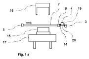
図1a及び図1bには、装置の基本的な構造が示されている。糸又は粗糸の準備は、多数の繰出しステーションによって行われ、これらの繰出しステーションにおいては、繊維材料が、スプール又は糸玉(いわゆるボビン)の形で準備され、複数の列1,2において互いに並んで、相前後して、又は互いに上下に配置されている。ボビンはまた、図1aに示すように、上側列及び下側列を形成してもよい。糸又は粗糸の始端部20は、使用される繰出しステーション3,4のためのそれぞれ使用される領域においてだけ略示されている。他のすべての始端部も、相応な糸引渡し箇所14に挿通され、その結果始端部を、所属のグリッパによって引取りポジション9において把持することができる。これは例えば一緒にボビンクリール(Spulengatter)とも呼ばれる。
1a and 1b show the basic structure of the device. The preparation of the yarn or the roving is carried out by a number of feeding stations, in which the fiber material is prepared in the form of spools or yarn balls (so-called bobbins) and is aligned with each other in a plurality of
他方の側においてグリッパ5は、その最大ポジション8において示されており、これらの最大ポジション8は、この場合出発ポジションにも相当する。1つのグリッパのクランプ幅はbで示され、すべてのグリッパの総クランプ幅はBで示されている。図面には等しい幅のグリッパだけが示されているが、もちろん、異なった幅を有するグリッパも可能である。グリッパはまた、必ずしも、その最大ポジションと引取りポジションとを同一線上に有する必要はない。さらにリフティングテーブル17上における第1の成形型15が示され、かつ、フードとして形成されている第2の成形型16が、出発ポジションにおいて、つまりグリッパの移動路(Pfad)の外側に示されている。第2の成形型は、平面図では示されていない。また、第2の成形型のための相応な移動装置又は降下装置も特別には示されていない。さらに、結合材料タンク19が設けられており、この結合材料タンク19は、例えば繰出しステーションの列の間に配置されていてよい。
On the other side, the
グリッパ6は、引取りポジションにあり、装置における該グリッパの配置に相当する糸又は粗糸を、グリッパ6が糸又は粗糸の始端部を把持することによって、引き取る。グリッパは、例えばロッド又はピストンであるガイド装置7によって移動可能である。これらのグリッパは個々に、しかしながら単に直線的にかつ平行な移動路において互いに並んで、引取りポジションと最大ポジションとの間において運動することができる。これによって単純な自動化及び迅速かつ平行な運動が可能である。図示のように、複数の繰出しステーションを1つのグループにまとめること、及び1つのグリッパに対応配設させることが可能である。1つのグリッパは複数の糸又は粗糸を一緒に把持することができる。いずれにせよ、グリッパの数と少なくとも同じ数の繰出しステーションが設けられていることが望ましい。
The
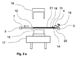
図2a,図2bには、張設された糸又は粗糸21が示されており、これらの糸又は粗糸21をグリッパ10はその中間ポジションへの移動によって引き出している。この過程は、アクティブに駆動される繰出し動作によって促進することができる。中間ポジションは、成形型の外輪郭に近くに、もしくは、成形型がその立体賦形ポジションにもたらされた場合における、外輪郭の後における位置の近くにある。糸又は粗糸21と一緒に、例えば結合糸又は結合フリースである結合材料18もまた、グリッパによって一緒に張設することができる。図示のように繰出しステーションの上側列と下側列とが設けられていてよいので、結合材料は、糸又は粗糸の上側の群と下側の群との間において張設される。引出し時に結合材料は糸引渡し箇所14の領域において、特に加熱装置によって、予め活性化することができるので、糸又は粗糸は立体賦形の開始時と同時に既に幾分互いに固定される。さらに糸引渡し箇所14の領域には、拡開装置が設けられており、この拡開装置は、単列又は複数列の爪(Zinke)を備えた一種のコームとして形成することができる。このようにして、糸又は粗糸が面を覆うように互いに並んで位置し、かつ後の立体賦形時にも側方に滑り出さないことが、保証される。拡開装置は糸道に沿って又はグリッパ移動路に沿って移動可能であってよい。さらに、糸張力測定装置13のための可能性も図示されている。
2a and 2b show tensioned yarns or
立体賦形というのは、成形型を用いて糸又は粗糸を変形すること、もしくは所定の形にすることである。立体賦形は単数又は複数の段階において行うことができ、この場合単数又は複数の成形型が同時に又は相前後して、張設された糸又は粗糸から成る層へと移動することができる。立体賦形中に、糸張力を調整すると、特に一定に保つと有利である。すなわち糸又は粗糸は、立体賦形のために成形型の相応な箇所においてどの程度必要であるかに応じて、送出される。このことを達成するために、ブレーキ及びクラッチ装置を設けることができる。各繰出しステーションに又は繰出しステーションの各グループに、相応な制御装置が対応配設されていると、好適である。このように構成されていると、糸又は粗糸が過剰に負荷(張力)を受けること又は極めてルーズに配設されることが、阻止される。糸張力は、糸引渡し箇所の領域及び/又は繰出しステーションと糸引渡し箇所との間における適宜な測定装置によっても、測定することができる。糸張力の値は好ましくは1〜50N/m2である。 The three-dimensional shaping means that a yarn or a roving yarn is deformed using a mold or is formed into a predetermined shape. Three-dimensional shaping can be carried out in one or more stages, in which case one or more molds can be moved simultaneously or in succession into layers of stretched yarns or rovings. If the yarn tension is adjusted during three-dimensional shaping, it is particularly advantageous to keep it constant. That is, the yarn or the roving yarn is sent out depending on how much it is necessary at the appropriate part of the mold for three-dimensional shaping. To accomplish this, a brake and clutch device can be provided. It is preferable that a corresponding control device is arranged corresponding to each feeding station or each group of feeding stations. If constituted in this way, the yarn or the roving yarn is prevented from being overloaded (tensioned) or arranged very loosely. The yarn tension can also be measured by an appropriate measuring device between the region of the yarn delivery location and / or between the feeding station and the yarn delivery location. The value of the yarn tension is preferably 1 to 50 N / m 2 .
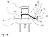
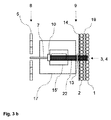
図3a及び図3bには、第1の立体賦形後における状態が示されている。リフティングテーブル17によって第1の成形型15′は立体賦形ポジションに移動させられている。これによって糸又は粗糸22は変位させられ、成形型15′によって立体賦形される。グリッパ10は、成形型15′の外輪郭の近傍において糸の始端部を固定する。このステップの後で、択一的に又は追加的に結合材料を、糸又は粗糸に塗布又は噴霧することができる。
3a and 3b show the state after the first three-dimensional shaping. The first molding die 15 ′ is moved to the three-dimensional shaping position by the lifting table 17. As a result, the yarn or the
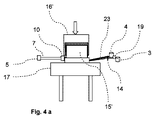
次のステップにおいて糸又は粗糸は、立体賦形ポジションに移動させられた第2の成形型16′を用いて、さらに立体賦形もしくは変形される(図4a及び図4b)。間に糸又は粗糸の層を挟み込んでいる両方の成形型の共働によって、正確な形状付与が可能である。両方の成形型が押し合わされ、一方の成形型、好ましくは第2の成形型が、又は両方の成形型が加熱されていてよく、その結果結合材料は活性化され、糸又は粗糸は形状安定的に固定されて1つの層を形成する。固定と同時に又は固定の後で、糸又は粗糸は成形型の両側において、つまりグリッパと成形型との間及び糸引渡し箇所と成形型との間において、切断される。1実施形態では、切断装置は第1又は第2の成形型に結合されている。この場合切断が少なくとも、糸引渡し箇所の側において成形型の近傍において行われると、好適である。これによって高価な繊維材料における切り屑の発生が僅かになり、繊維プリフォームの僅かな後処理しか必要でなくなる。 In the next step, the yarn or the coarse yarn is further three-dimensionally shaped or deformed using the second mold 16 'moved to the three-dimensional shaping position (FIGS. 4a and 4b). Accurate shaping is possible by the cooperation of both molds sandwiching a layer of yarn or roving yarn between them. Both molds may be pressed together, one mold, preferably the second mold, or both molds may be heated so that the binding material is activated and the yarn or roving is shape stable Fixed to form a layer. Simultaneously or after fixing, the yarn or roving is cut on both sides of the mold, ie between the gripper and the mold and between the thread delivery point and the mold. In one embodiment, the cutting device is coupled to the first or second mold. In this case, it is preferable that the cutting is performed at least in the vicinity of the forming die on the yarn delivery point side. This reduces the generation of chips in the expensive fiber material and requires only a small amount of post-treatment of the fiber preform.
切断された糸又は粗糸23は、巻戻し装置を介して再び引き戻されて巻き上げられるか又は、相応な糸ガイドを介して中間貯蔵される。この巻戻し動作は、再び糸又は粗糸の始端部が糸引渡し箇所14の領域に位置し、かつ該始端部をグリッパによって引き取ることができるように行われ、しかもこの際に、過度に多くの切り屑が発生することはない。始端部を検出するためには、センサを使用することができる。
The cut yarn or
図5a及び図5bにおいては糸又は粗糸は、既に巻き戻されているか又は糸引渡し箇所において切断されており、従って再び始端部は糸引渡し箇所に位置している。グリッパにおいても、繊維材料の切り屑24は極めて僅かしか存在しない。それというのは、グリッパはそれぞれ成形型の外輪郭の近傍にかつ該外輪郭に沿って位置決めされ、かつ使用されたもしくは必要な量の糸だけを張設したからである。成形型15,16は再びその出発ポジションにもたらされる。第1の成形型には、第1の成形された層25が残っている。
In FIGS. 5a and 5b, the yarn or the coarse yarn has already been rewound or cut at the yarn delivery point, so that the starting end is again located at the yarn delivery point. Even in the gripper, very little
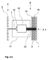
図6a及び図6bには、第1及び第2の成形型15,16が、回転させられた位置で示されている。この場合成形型15,16は90°回転させられている。しかしながら他の回転角、例えば約30°、45°、60°の回転角も可能であり、又は旋回も可能である。回転角は好ましくは10〜170°である。このことは、糸又は粗糸の別の層をどのようにかつどのような繊維配向で装着したいかによって決定される。必要なグリッパ6′は、使用される糸又は粗糸の始端部20を把持するために、引取りポジションにある。
In FIGS. 6a and 6b, the first and
次いで、別の層の糸又は粗糸が、グリッパの中間ポジションに到るまで張設され、かつ立体賦形され、この場合第1及び第2の成形型15′,16′は立体賦形ポジションに移動させられる。 Next, another layer of yarn or roving yarn is stretched until it reaches the intermediate position of the gripper and is three-dimensionally shaped, in which case the first and second molds 15 ', 16' are in three-dimensional shaping position. Moved to.
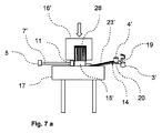
図7a及び図7bには、装置が、糸又は粗糸が切断された後の状態で示されている。使用されたグリッパ11は、中間ポジションに位置している。方形ではない成形型の場合又は他の回転角の場合、グリッパ11は、異なった中間ポジションに位置していてもよい。糸又は粗糸及び場合によっては結合材料から成る別の層は、同様に加熱及び/又はプレスによって、形状安定的に固定され、かつ第1の層に結合されることができる。そして両方の層は一緒に繊維プリフォーム28を形成する。
In FIGS. 7a and 7b, the device is shown after the yarn or roving has been cut. The used
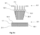
図8aには、例えばエンジンフード用の繊維プリフォームを製造する場合に使用することができる別の実施形態が示されている。使用されるグリッパ10.1は中間ポジションに位置し、使用されないグリッパ5.1は最大ポジション8.1に位置している。第1の成形型15.1において、糸又は粗糸の第1の層25.1が立体賦形されかつ固定されている。第2の成形型は図示されていない。糸又は粗糸の貯蔵は、繰出しステーション1.1,2.1において行われる。さらに結合材料タンク19.1及び糸引渡し箇所14.1が設けられている。 FIG. 8a shows another embodiment that can be used, for example, in producing a fiber preform for an engine hood. The used gripper 10.1 is located in the intermediate position and the unused gripper 5.1 is located in the maximum position 8.1. In the first mold 15.1, the first layer 25.1 of yarn or roving is three-dimensionally shaped and fixed. The second mold is not shown. Yarn or roving is stored at the feeding stations 1.1 and 2.1. Furthermore, a binding material tank 19.1 and a thread delivery point 14.1 are provided.
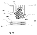
単数又は複数の別の層の装着は、同一の装置において行うことも、又は、第1の成形型が第1の層と一緒に引き渡される単数又は複数の別の本発明による装置において行うこともできる。図8bでは別の層26.1が、回転させられた成形型に立体賦形されている。図面を見易くするために、一対の糸又は粗糸しか示されていない。使用されたグリッパ11.1は、成形型の外輪郭に沿って位置し、可能な限り正確に成形型に追従する。さらなる正確な適合のために、細いグリッパ又は種々異なった幅のグリッパを使用することができる。 The mounting of one or more other layers can be done in the same device or in one or more other devices according to the invention in which the first mold is delivered together with the first layer. it can. In FIG. 8b, another layer 26.1 is three-dimensionally shaped in a rotated mold. For ease of viewing the drawing, only a pair of yarns or rovings are shown. The gripper 11.1 used is located along the outer contour of the mold and follows the mold as accurately as possible. For a more precise fit, thin grippers or different width grippers can be used.
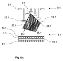
図8cには、さらに別の層が装着された状態が示されている。使用されたグリッパ12.1は、再び外輪郭に沿って位置している。固定後に、これらの層は一緒になって繊維プリフォーム28.1を形成する。 FIG. 8c shows a state in which a further layer is mounted. The used gripper 12.1 is again located along the outer contour. After fixing, these layers together form a fiber preform 28.1.
1,1.1,2,2.1 繰出しステーションの列
3,3′,4,4′ 使用中の繰出しステーション
5,5.1 グリッパの列
6,6′ 引取りポジションにおけるグリッパ
7,7.1,7′,7.1′ グリッパ用のガイド装置
8,8.1 最大ポジションの位置
9,9.1 引取りポジションの位置
10,10.1,11,11.1,12,12.1 中間ポジションにおけるグリッパ
13,13′ 糸張力用の測定装置
14,14.1 糸引渡し箇所(場合によっては拡開装置及び/又は結合剤予備活性のための装置をも備える)
15 出発ポジションにおける第1の成形型
15′,15.1 立体賦形ポジションにおける第1の成形型
16 出発ポジションにおける第2の成形型
16′ 立体賦形ポジションにおける第2の成形型
17 リフティングテーブル
18 結合材料
19,19.1 結合材料タンク
20,20′糸又は粗糸の始端部
21 張設された糸又は粗糸
22 立体賦形された糸又は粗糸
23,23′ 切断された糸又は粗糸
24 切り屑
25 糸又は粗糸の第1の層
26.1,27.1 糸又は粗糸の別の層
28,28.1 繊維プリフォーム
b 1つのグリッパのクランプ幅
B すべてのグリップの総クランプ幅
1, 1.1, 2, 2.1
DESCRIPTION OF
Claims (20)
第1の成形型(15,15′,15.1)は、前記最大ポジション(8,8.1)と前記糸引渡し箇所(14,14.1)との間の接続ラインの領域に立体賦形ポジションを有し、かつ前記接続ラインの略垂直方向外側に出発ポジションを有しており、垂線に対して+/−30°までの偏差が可能であり、前記糸又は粗糸の糸張力を調整する調整装置が設けられていることを特徴とする、繊維プリフォームを製造する装置。 A preform in the preparation of fiber-reinforced plastic member, a device for producing a fiber preform (28,28.1), the apparatus comprising a plurality for providing a plurality of yarns or rovings Each of the feeding stations (1, 1.1, 2, 2.1, 3, 3 ', 4, 4') and the starting end (20, 20 ') of one or more yarns or roving yarns, respectively A plurality of grippers (5, 5.1) and at least one first mold (15, 15 ', 15.1, 16, 16'), each said gripper (5, 5 .1) can reciprocate in the movement path between the maximum position (8, 8.1) and the take-off position (9, 9.1), and the take-up position (9, 9.1) is It is provided at the thread delivery point (14, 14.1), and is fed out from the maximum position (8, 8.1). Is located in the vicinity of the station (1,1.1,2,2.1), in the apparatus,
The first mold (15, 15 ', 15.1) is three-dimensionally applied in the region of the connection line between the maximum position (8, 8.1) and the yarn delivery point (14, 14.1). And has a starting position substantially outside the connecting line in the vertical direction , and a deviation up to +/− 30 ° with respect to the perpendicular is possible. An apparatus for producing a fiber preform, characterized in that an adjusting apparatus for adjusting is provided.
複数のグリッパ(5,5.1)を用いて糸又は粗糸を張設する方法ステップと、
第1の成形型(15,15′,15.1)を用いて前記糸又は粗糸を立体賦形する方法ステップと、
前記糸又は粗糸を切断する方法ステップと、
を相前後して有する、方法において、
張設された前記糸又は粗糸(21)の領域内への前記第1の成形型(15,15′,15.1)の進入移動によって立体賦形を行い、前記糸又は粗糸の糸張力を前記進入移動中に調整する
ことを特徴とする、方法。 A preform in the preparation of fiber-reinforced plastic member using the apparatus of any one of claims 1 to 14, there in a manner to produce a fiber preform (28,28.1) Te,
And method steps of tensioning the yarn or roving with a plurality of grippers (5,5.1),
First mold (15, 15 ', 15.1) and method steps of the three-dimensional shaping of the yarn or roving with,
A method step of cutting the yarn or the roving yarn;
In a method comprising:
Three-dimensional shaping is performed by moving the first forming die (15, 15 ', 15.1) into the stretched yarn or roving yarn (21), and the yarn or roving yarn A method comprising adjusting tension during said approach movement.
Applications Claiming Priority (3)
| Application Number | Priority Date | Filing Date | Title |
|---|---|---|---|
| DE102011007020A DE102011007020A1 (en) | 2011-04-08 | 2011-04-08 | Apparatus and process for the production of fiber moldings, which are in particular a precursor in the production of fiber-reinforced plastic components |
| DE102011007020.6 | 2011-04-08 | ||
| PCT/EP2012/051293 WO2012136393A1 (en) | 2011-04-08 | 2012-01-27 | Device and method for producing fiber preforms, which are a precursor in the production of fiber-reinforced plastic components in particular |
Publications (3)
| Publication Number | Publication Date |
|---|---|
| JP2014512287A JP2014512287A (en) | 2014-05-22 |
| JP2014512287A5 JP2014512287A5 (en) | 2015-03-05 |
| JP6000331B2 true JP6000331B2 (en) | 2016-09-28 |
Family
ID=45558717
Family Applications (1)
| Application Number | Title | Priority Date | Filing Date |
|---|---|---|---|
| JP2014503037A Expired - Fee Related JP6000331B2 (en) | 2011-04-08 | 2012-01-27 | An apparatus and method for producing a fiber preform, which is a preform in particular for producing a fiber-reinforced plastic member |
Country Status (6)
| Country | Link |
|---|---|
| US (1) | US9539766B2 (en) |
| EP (1) | EP2694262B1 (en) |
| JP (1) | JP6000331B2 (en) |
| CN (1) | CN103492143B (en) |
| DE (1) | DE102011007020A1 (en) |
| WO (1) | WO2012136393A1 (en) |
Families Citing this family (17)
| Publication number | Priority date | Publication date | Assignee | Title |
|---|---|---|---|---|
| DE102010015199B9 (en) | 2010-04-16 | 2013-08-01 | Compositence Gmbh | Fiber guiding device and apparatus for constructing a three-dimensional preform |
| DE102011007020A1 (en) | 2011-04-08 | 2012-10-11 | Voith Patent Gmbh | Apparatus and process for the production of fiber moldings, which are in particular a precursor in the production of fiber-reinforced plastic components |
| DE102011100640A1 (en) | 2011-05-05 | 2012-11-08 | Compositence Gmbh | Method and apparatus for making fiber webs and component preforms from fibers |
| DE102012007439A1 (en) | 2012-04-13 | 2013-10-17 | Compositence Gmbh | Laying head and apparatus and method for building a three-dimensional preform for a component made of a fiber composite material |
| DE102012218186A1 (en) * | 2012-10-05 | 2014-04-10 | Voith Patent Gmbh | Apparatus for the production of fiber preforms, which in particular constitute a precursor in the production of fiber-reinforced plastic components |
| DE102012218178A1 (en) | 2012-10-05 | 2013-11-21 | Voith Patent Gmbh | Device useful for producing fiber preforms, preferably a precursor in the preparation of fiber-reinforced plastic components, comprises many unwinding stations for providing many yarns, rovings or ribbons, and many grippers |
| KR20150091355A (en) * | 2012-11-30 | 2015-08-10 | 디펜바허 게엠베하 마쉬넨- 운트 안라게바우 | Method and placement machine for placing and attaching strip sections to a part to be produced |
| WO2014102015A1 (en) * | 2012-12-28 | 2014-07-03 | Compositence Gmbh | Method and device for producing three-dimensional laid fibre scrims and component preforms made of fibres in two steps |
| DE102013111794A1 (en) * | 2013-10-25 | 2015-04-30 | Airbus Defence and Space GmbH | Repeating unit, multi-needle machine and process for producing reinforced materials |
| US10773469B2 (en) * | 2017-02-21 | 2020-09-15 | Seriforge Inc. | Systems and methods of converting fiber into shaped fabric plies for composite preforms and products |
| WO2019008443A1 (en) * | 2017-07-05 | 2019-01-10 | Coats Group Plc | Process of making a fiber preform of commingled fiber bundle for overmolding |
| CN110667136A (en) * | 2019-09-06 | 2020-01-10 | 长沙晶优新材料科技有限公司 | Method for preparing profiling prefabricated part by needling |
| CN111101248B (en) * | 2019-11-15 | 2021-08-20 | 乐昌市恒发纺织企业有限公司 | Automatic wiring method in yarn weaving process |
| CN111098526B (en) * | 2019-12-30 | 2021-11-16 | 沈阳理工大学 | Preparation method of high-strength pressure-resistant arc-shaped top head workpiece |
| CN112277338B (en) * | 2020-09-30 | 2022-04-26 | 陕西科技大学 | Device and method for efficiently reinforcing composite material by continuous fibers at any angle |
| US11752711B2 (en) * | 2021-01-18 | 2023-09-12 | Spirit Aerosystems, Inc. | System and method for promoting inter-ply slippage |
| CN121005320B (en) * | 2025-10-28 | 2026-03-10 | 常州超峰胶线科技有限公司 | Constant tension paying-off device for polyester rope |
Family Cites Families (17)
| Publication number | Priority date | Publication date | Assignee | Title |
|---|---|---|---|---|
| US2934317A (en) * | 1954-05-05 | 1960-04-26 | Studebaker Packard Corp | Prestressed compressor blade |
| DK92684D0 (en) * | 1983-04-20 | 1984-02-23 | Itt | PROFILE OR CONSTRUCTION ELEMENT OF AN ARMED COMPOSITION MATERIAL AND MACHINE AND PROCEDURES FOR MANUFACTURING THEREOF |
| DE19922799B4 (en) * | 1999-05-18 | 2014-06-12 | Bayerische Motoren Werke Aktiengesellschaft | Process for producing a plastic molding |
| US6814916B2 (en) * | 2002-08-30 | 2004-11-09 | The Boeing Company | Forming method for composites |
| US7137182B2 (en) * | 2002-11-22 | 2006-11-21 | The Boeing Company | Parallel configuration composite material fabricator |
| CA2557088A1 (en) * | 2005-08-25 | 2007-02-25 | Ingersoll Machine Tools, Inc. | Replaceable creel in a fiber placement machine |
| CN2885551Y (en) * | 2005-12-08 | 2007-04-04 | 北京玻钢院复合材料有限公司 | Production process of fibre preformed body |
| JP4677950B2 (en) | 2006-03-31 | 2011-04-27 | 株式会社豊田自動織機 | Three-dimensional fiber structure and composite material, and method for producing three-dimensional fiber structure |
| JP4775090B2 (en) * | 2006-04-14 | 2011-09-21 | 株式会社豊田自動織機 | Manufacturing method of fiber reinforced composite material |
| FR2912953B1 (en) | 2007-02-28 | 2009-04-17 | Coriolis Composites Sa | FIBER APPLICATION MACHINE WITH FLEXIBLE FIBER DELIVERY TUBES |
| CN101462358B (en) * | 2007-12-19 | 2013-09-11 | 维斯塔斯风力系统有限公司 | An apparatus for preparing a pre-form |
| US8116899B1 (en) * | 2008-02-27 | 2012-02-14 | Ebert Composites Corporation | Computer numerical control of fiber tension in fiber processing |
| DE102008011658A1 (en) | 2008-02-28 | 2009-09-03 | Daimler Ag | Method for manufacturing fiber reinforced plastic component, involves producing fiber preform of fibers, with which fibers at crossing area are over-crossed |
| DE102008042574B4 (en) | 2008-10-02 | 2010-06-10 | Airbus Deutschland Gmbh | Apparatus for depositing and draping sections of a reinforcing fiber structure to produce a profile preform and method |
| DE102009042384B4 (en) * | 2009-09-21 | 2013-08-08 | Liba Maschinenfabrik Gmbh | A method and apparatus for applying a unidirectional fiber ply to a moving support and method of making a multiaxial fabric |
| JP5751751B2 (en) * | 2009-12-25 | 2015-07-22 | 三菱重工業株式会社 | Reinforcing fiber substrate laminating apparatus and laminating method |
| DE102011007020A1 (en) | 2011-04-08 | 2012-10-11 | Voith Patent Gmbh | Apparatus and process for the production of fiber moldings, which are in particular a precursor in the production of fiber-reinforced plastic components |
-
2011
- 2011-04-08 DE DE102011007020A patent/DE102011007020A1/en not_active Withdrawn
-
2012
- 2012-01-27 WO PCT/EP2012/051293 patent/WO2012136393A1/en not_active Ceased
- 2012-01-27 JP JP2014503037A patent/JP6000331B2/en not_active Expired - Fee Related
- 2012-01-27 EP EP12701886.9A patent/EP2694262B1/en active Active
- 2012-01-27 CN CN201280017470.8A patent/CN103492143B/en not_active Expired - Fee Related
-
2013
- 2013-10-08 US US14/048,551 patent/US9539766B2/en not_active Expired - Fee Related
Also Published As
| Publication number | Publication date |
|---|---|
| JP2014512287A (en) | 2014-05-22 |
| US20140035195A1 (en) | 2014-02-06 |
| EP2694262B1 (en) | 2015-08-19 |
| US9539766B2 (en) | 2017-01-10 |
| WO2012136393A1 (en) | 2012-10-11 |
| EP2694262A1 (en) | 2014-02-12 |
| CN103492143B (en) | 2016-10-26 |
| DE102011007020A1 (en) | 2012-10-11 |
| CN103492143A (en) | 2014-01-01 |
Similar Documents
| Publication | Publication Date | Title |
|---|---|---|
| JP6000331B2 (en) | An apparatus and method for producing a fiber preform, which is a preform in particular for producing a fiber-reinforced plastic member | |
| JP6109145B2 (en) | An apparatus and method for producing a fiber preform, which is a preform in particular for producing a fiber-reinforced plastic member | |
| JP6000330B2 (en) | An apparatus and method for producing a fiber preform, which is a preform in particular for producing a fiber-reinforced plastic member | |
| US8568549B2 (en) | Process and device for manufacturing a preform for a load path aligned fiber composite structure | |
| CN105980139B (en) | Unidirectional reinforcement, method for preparing unidirectional reinforcement and use thereof | |
| CN101680136B (en) | Spreading device for spreading out fibre filament bundles, and spreading method carried out using same | |
| US11491741B2 (en) | Process for producing composite material parts by impregnating a specific preform | |
| JP5663581B2 (en) | Automated drape forming device | |
| US10894341B2 (en) | Method for producing preforms with application of a binder to dry fiber, and corresponding machine | |
| CN108472883B (en) | Placement equipment for fiber roving | |
| KR20130091648A (en) | Device and method for producing laid fibre fabrics | |
| CN104302465B (en) | horizontal laying of fibers | |
| JP2013505155A5 (en) | ||
| KR101788508B1 (en) | Manufacturing apparatus of multiaxial fiber sheet and method thereof | |
| TWI589422B (en) | Deposition device for controlled deposition of reinforcing fiber bundles | |
| JP2005219373A (en) | Automatic device for laminating reinforcing fibers and method for producing fiber-reinforced preform |
Legal Events
| Date | Code | Title | Description |
|---|---|---|---|
| A521 | Request for written amendment filed |
Free format text: JAPANESE INTERMEDIATE CODE: A523 Effective date: 20150113 |
|
| A621 | Written request for application examination |
Free format text: JAPANESE INTERMEDIATE CODE: A621 Effective date: 20150113 |
|
| A977 | Report on retrieval |
Free format text: JAPANESE INTERMEDIATE CODE: A971007 Effective date: 20151022 |
|
| A131 | Notification of reasons for refusal |
Free format text: JAPANESE INTERMEDIATE CODE: A131 Effective date: 20151102 |
|
| A601 | Written request for extension of time |
Free format text: JAPANESE INTERMEDIATE CODE: A601 Effective date: 20160202 |
|
| A601 | Written request for extension of time |
Free format text: JAPANESE INTERMEDIATE CODE: A601 Effective date: 20160302 |
|
| A521 | Request for written amendment filed |
Free format text: JAPANESE INTERMEDIATE CODE: A523 Effective date: 20160401 |
|
| TRDD | Decision of grant or rejection written | ||
| A01 | Written decision to grant a patent or to grant a registration (utility model) |
Free format text: JAPANESE INTERMEDIATE CODE: A01 Effective date: 20160801 |
|
| A61 | First payment of annual fees (during grant procedure) |
Free format text: JAPANESE INTERMEDIATE CODE: A61 Effective date: 20160830 |
|
| R150 | Certificate of patent or registration of utility model |
Ref document number: 6000331 Country of ref document: JP Free format text: JAPANESE INTERMEDIATE CODE: R150 |
|
| R250 | Receipt of annual fees |
Free format text: JAPANESE INTERMEDIATE CODE: R250 |
|
| R250 | Receipt of annual fees |
Free format text: JAPANESE INTERMEDIATE CODE: R250 |
|
| R250 | Receipt of annual fees |
Free format text: JAPANESE INTERMEDIATE CODE: R250 |
|
| R250 | Receipt of annual fees |
Free format text: JAPANESE INTERMEDIATE CODE: R250 |
|
| LAPS | Cancellation because of no payment of annual fees |