JP6000276B2 - Related methods for joining lap joints and fuselage sections - Google Patents
Related methods for joining lap joints and fuselage sections Download PDFInfo
- Publication number
- JP6000276B2 JP6000276B2 JP2013544479A JP2013544479A JP6000276B2 JP 6000276 B2 JP6000276 B2 JP 6000276B2 JP 2013544479 A JP2013544479 A JP 2013544479A JP 2013544479 A JP2013544479 A JP 2013544479A JP 6000276 B2 JP6000276 B2 JP 6000276B2
- Authority
- JP
- Japan
- Prior art keywords
- strip
- fixture
- tie
- shear tie
- sections
- Prior art date
- Legal status (The legal status is an assumption and is not a legal conclusion. Google has not performed a legal analysis and makes no representation as to the accuracy of the status listed.)
- Active
Links
- 238000000034 method Methods 0.000 title claims description 20
- 239000002131 composite material Substances 0.000 claims description 40
- RTAQQCXQSZGOHL-UHFFFAOYSA-N Titanium Chemical compound [Ti] RTAQQCXQSZGOHL-UHFFFAOYSA-N 0.000 claims description 26
- 239000010936 titanium Substances 0.000 claims description 26
- 229910052719 titanium Inorganic materials 0.000 claims description 26
- 239000000945 filler Substances 0.000 claims description 18
- 239000000463 material Substances 0.000 description 23
- 210000001503 joint Anatomy 0.000 description 20
- 229910052751 metal Inorganic materials 0.000 description 15
- 239000002184 metal Substances 0.000 description 15
- 229920002430 Fibre-reinforced plastic Polymers 0.000 description 12
- 239000011151 fibre-reinforced plastic Substances 0.000 description 12
- 238000005553 drilling Methods 0.000 description 7
- 238000010168 coupling process Methods 0.000 description 6
- 150000002739 metals Chemical class 0.000 description 6
- 230000008878 coupling Effects 0.000 description 5
- 238000005859 coupling reaction Methods 0.000 description 5
- 229910001026 inconel Inorganic materials 0.000 description 5
- 230000009471 action Effects 0.000 description 4
- 229910000831 Steel Inorganic materials 0.000 description 3
- 239000010959 steel Substances 0.000 description 3
- 239000000835 fiber Substances 0.000 description 2
- 238000007689 inspection Methods 0.000 description 2
- 238000009434 installation Methods 0.000 description 2
- 230000004048 modification Effects 0.000 description 2
- 238000012986 modification Methods 0.000 description 2
- 241001529936 Murinae Species 0.000 description 1
- 229910018487 Ni—Cr Inorganic materials 0.000 description 1
- 229910052782 aluminium Inorganic materials 0.000 description 1
- XAGFODPZIPBFFR-UHFFFAOYSA-N aluminium Chemical compound [Al] XAGFODPZIPBFFR-UHFFFAOYSA-N 0.000 description 1
- 238000005452 bending Methods 0.000 description 1
- 230000015572 biosynthetic process Effects 0.000 description 1
- VNNRSPGTAMTISX-UHFFFAOYSA-N chromium nickel Chemical compound [Cr].[Ni] VNNRSPGTAMTISX-UHFFFAOYSA-N 0.000 description 1
- 238000010586 diagram Methods 0.000 description 1
- -1 for example Substances 0.000 description 1
- 239000007769 metal material Substances 0.000 description 1
- 238000005192 partition Methods 0.000 description 1
- 238000000926 separation method Methods 0.000 description 1
- 229910000601 superalloy Inorganic materials 0.000 description 1
Images


Classifications
-
- B—PERFORMING OPERATIONS; TRANSPORTING
- B64—AIRCRAFT; AVIATION; COSMONAUTICS
- B64C—AEROPLANES; HELICOPTERS
- B64C1/00—Fuselages; Constructional features common to fuselages, wings, stabilising surfaces or the like
- B64C1/06—Frames; Stringers; Longerons ; Fuselage sections
- B64C1/12—Construction or attachment of skin panels
-
- B—PERFORMING OPERATIONS; TRANSPORTING
- B64—AIRCRAFT; AVIATION; COSMONAUTICS
- B64C—AEROPLANES; HELICOPTERS
- B64C1/00—Fuselages; Constructional features common to fuselages, wings, stabilising surfaces or the like
- B64C1/06—Frames; Stringers; Longerons ; Fuselage sections
- B64C1/068—Fuselage sections
-
- B—PERFORMING OPERATIONS; TRANSPORTING
- B64—AIRCRAFT; AVIATION; COSMONAUTICS
- B64C—AEROPLANES; HELICOPTERS
- B64C1/00—Fuselages; Constructional features common to fuselages, wings, stabilising surfaces or the like
- B64C2001/0054—Fuselage structures substantially made from particular materials
- B64C2001/0072—Fuselage structures substantially made from particular materials from composite materials
-
- Y—GENERAL TAGGING OF NEW TECHNOLOGICAL DEVELOPMENTS; GENERAL TAGGING OF CROSS-SECTIONAL TECHNOLOGIES SPANNING OVER SEVERAL SECTIONS OF THE IPC; TECHNICAL SUBJECTS COVERED BY FORMER USPC CROSS-REFERENCE ART COLLECTIONS [XRACs] AND DIGESTS
- Y02—TECHNOLOGIES OR APPLICATIONS FOR MITIGATION OR ADAPTATION AGAINST CLIMATE CHANGE
- Y02T—CLIMATE CHANGE MITIGATION TECHNOLOGIES RELATED TO TRANSPORTATION
- Y02T50/00—Aeronautics or air transport
- Y02T50/40—Weight reduction
Description
本開示の実施形態は、一般に、重ね継ぎおよび関連する結合方法に関し、より詳細には、重ね継ぎおよび胴体セクションを結合するための関連する方法に関する。 Embodiments of the present disclosure generally relate to lap joints and related coupling methods, and more particularly to related methods for coupling lap joints and fuselage sections.
構造物のセクションは、セクション間を埋め、かつ、これらを構造的に結合する重ね継ぎにより時として結合されることがある。図1に示すように、例えば、航空機の胴体10は、互いに結合されている複数のセクション12から形成されていてもよい。隣り合う胴体セクション12同士は、胴体セクションを構造的に相互接続する役割を果たす重ね継ぎにより結合されていてもよい。例えば、隣り合う胴体セクションは、胴体10の内部に位置し、かつ、隣り合う胴体セクション12間を埋めるフレームまたは隔壁からなる重ね継ぎにより結合されていてもよい。重ね継ぎはまた、フレームを貫通して延在し、かつ、胴体セクション12へのフレームの結合を容易にする複数の貫通取り付け具を含んでいてもよい。 The sections of the structure may sometimes be joined by lap joints that fill the sections and structurally connect them. As shown in FIG. 1, for example, an aircraft fuselage 10 may be formed from a plurality of sections 12 coupled together. Adjacent fuselage sections 12 may be joined by lap joints that serve to structurally interconnect the fuselage sections. For example, the adjacent fuselage sections may be connected to each other by a lap joint formed of a frame or a partition wall that is located inside the fuselage 10 and fills between the adjacent fuselage sections 12. The lap joint may also include a plurality of through fittings that extend through the frame and facilitate the coupling of the frame to the fuselage section 12.
示されているように、例えば図2において、一対の隣り合う胴体セクションの各々は、複数の長手方向に延在する縦通材14と、該複数の縦通材を覆っている外板16とを含んでいてもよい。一対の隣り合う胴体セクション12をまとめてもよく、該一対の隣り合う胴体セクションに重ね継ぎを取り付けることにより、隣り合う胴体セクション間の境界面を埋めてもよい。図2の実施例において、フレームは、胴体セクションに近接して位置し、かつ、胴体セクション間の境界面を埋めるフレーム外側コード18を含む。フレームはまた、半径方向内向きに延在するウェブ20と、内側コード22とを含む。図2の重ね継ぎはまた、複数の貫通取り付け具24を含む。示されているように、フレーム、およびより詳細には、ウェブ20は、貫通取り付け具24が延在している複数の開口26を画定している。示されているように、貫通取り付け具24は、胴体セクション12の縦通材14の上に重なるようにフレームを超えて長手方向に延在するよう構成されている。この場合、各貫通取り付け具24は、胴体セクション12のうちの一方の縦通材14の上に重なる第1端と、他方の胴体セクションの縦通材の上に重なる対向する第2端とを有する。フレームと貫通取り付け具24との両方を含む重ね継ぎを胴体セクション12に接続することにより、重ね継ぎは、胴体セクション同士を構造的に結合する役割を果たす。
As shown, for example, in FIG. 2, each of a pair of adjacent fuselage sections includes a plurality of longitudinally extending
図2に示しているような重ね継ぎは、チタンなどの金属材料から形成されていてもよい。チタンは、比較的高価な材料なので、チタン製の重ね継ぎに付随する材料費は、航空機に付随するコストを不都合なほどに上昇させる。また、重ね継ぎは、フレームを貫通して延在して、フレームを胴体セクションに接続する締結具、および、貫通取り付け具を貫通して延在して、貫通取り付け具を胴体セクションの縦通材に接続する締結具といった複数の締結具により胴体セクションに取り付けられていてもよい。締結具を設置するためには、それぞれの締結具を収容するために重ね継ぎを貫通する複数の穴をまず開けねばならない。しかしながら、チタン製の重ね継ぎを貫通する穴を開けるにはかなりの時間がかかり、これにより、胴体セクションの組立てに要する時間およびそのような組立てに付随する人件費が増大する。さらに、チタン製の重ね継ぎを貫通して開けられた穴は概して、部品の分離およびバリ取りを要し、これにより、胴体の組立てに付随する時間およびコストがさらに増大する。 The lap joint as shown in FIG. 2 may be formed of a metal material such as titanium. Since titanium is a relatively expensive material, the material costs associated with titanium lap joints undesirably increase the costs associated with aircraft. The lap joint also extends through the frame to connect the frame to the fuselage section, and extends through the through fitting to pass the through fitting to the longitudinal section of the fuselage section. It may be attached to the fuselage section by a plurality of fasteners, such as fasteners connected to the body. In order to install the fasteners, a plurality of holes must first be drilled through the lap joint to accommodate the respective fasteners. However, it takes considerable time to drill a hole through a titanium lap joint, which increases the time required to assemble the fuselage section and the labor costs associated with such assembly. Furthermore, holes drilled through titanium lap joints generally require part separation and deburring, which further increases the time and cost associated with fuselage assembly.
したがって、隣り合う胴体セクションなどの構造物を効率的に結合するために、本開示の実施形態に係る重ね継ぎおよび関連する方法を提供する。これに関して、重ね継ぎおよび関連する方法は、重ね継ぎに付随する材料費を削減可能であり、かつ、重ね継ぎの設置に付随する時間および付随する人件費もまた削減可能である。さらに、いくつかの実施形態の結果として得られる重ね継ぎがより軽量である可能性があることは有利である。 Accordingly, in order to efficiently join structures such as adjacent fuselage sections, lap joints and related methods according to embodiments of the present disclosure are provided. In this regard, lap joints and associated methods can reduce the material costs associated with lap joints, and can also reduce the time and attendant labor costs associated with lap joint installation. Furthermore, it is advantageous that the lap splice resulting from some embodiments may be lighter.
一実施形態において、胴体セクションを結合するための重ね継ぎを提供し、ここで、該重ね継ぎは、胴体セクションの間を埋めるよう構成されている帯板と、帯板の上に重なるシヤタイと、帯板とシヤタイとが離間するように帯板とシヤタイとの間に位置付けられている取り付け具と、を含む。本実施形態の取り付け具は、帯板のそれぞれ反対側を超えて延在している第1および第2の長手方向に延在するセクションを有する。長手方向に延在する各セクションは、それぞれの胴体セクションの少なくとも2本の縦通材の上に重なるよう構成されている。 In one embodiment, a lap joint is provided for joining fuselage sections, wherein the lap joint is configured to fill a gap between the fuselage sections, and a shear tie overlying the strip. And a fixture positioned between the strip and the tie so that the strip and the tie are spaced apart. The fixture of this embodiment has first and second longitudinally extending sections that extend beyond opposite sides of the strip. Each longitudinally extending section is configured to overlie at least two stringers of the respective fuselage section.
帯板、シヤタイおよび取り付け具は、複合材料から形成されていてもよい。一実施形態において、取り付け具は、長手方向に延在する各セクションが、互いに離間され、かつ、それぞれの縦通材の上に重なる第1部材および第2部材を含むようなH字形である。本実施形態において、取り付け具は、シヤタイが据え付けられている第1および第2の長手方向に延在するセクション間の中間部をも含んでいてもよい。該重ね継ぎは、複数の取り付け具を含んでいてもよく、かつ、シヤタイは、互いに離間する複数の脚部を含んでいてもよい。そのようであるので、本実施形態のシヤタイの各脚部は、それぞれの取り付け具の中間部上に据え付けられていてもよい。これに加えて、帯板の一部が隣接した取り付け具の間から見えることにより、帯板の点検が可能となるように、複数の取り付け具が互いに離間されていてもよい。該重ね継ぎは、シヤタイ、取り付け具および帯板を胴体セクションに接続する複数の締結具をも含んでいてもよい。締結具は、例えば、チタンから形成されていてもよい。該重ね継ぎはまた、シヤタイに接続され、かつ、これの機内側にあるウェブおよび内側コードを含んでいてもよい。一実施形態の重ね継ぎは、取り付け具の第1および第2の長手方向に延在するセクションのそれぞれと縦通材との間に位置付けられている第1および第2充填材をも含んでいてもよい。 The strip, tie and attachment may be formed from a composite material. In one embodiment, the fixture is H-shaped such that each longitudinally extending section includes a first member and a second member that are spaced apart from each other and overlie the respective stringer. In this embodiment, the fixture may also include an intermediate portion between the first and second longitudinally extending sections on which the shear ties are installed. The lap joint may include a plurality of attachments, and the shear tie may include a plurality of legs spaced from one another. As such, each leg portion of the shear tie of the present embodiment may be installed on an intermediate portion of the respective fixture. In addition, a plurality of fixtures may be spaced apart from each other so that a portion of the strip can be seen from between adjacent fixtures so that the strip can be inspected. The lap joint may also include a plurality of fasteners that connect the sheath ties, attachments, and strips to the fuselage section. The fastener may be made of titanium, for example. The lap joint may also include a web and an inner cord connected to the sheath and on the inside of the aircraft. The lap joint of an embodiment also includes first and second fillers positioned between each of the first and second longitudinally extending sections of the fixture and the stringer. Also good.
別の実施形態において、複合材料から形成される帯板と、帯板の上に重なるシヤタイと、帯板とシヤタイとが離間するように帯板とシヤタイとの間に位置するH字形取り付け具とを含む重ね継ぎを提供する。H字形取り付け具もまた、複合材料から形成されていてもよい。 In another embodiment, a strip formed from a composite material, a shear tie overlying the strip, and an H-shaped fixture positioned between the strip and the shear tie such that the strip and the shear tie are spaced apart Provides a lap joint including. The H-shaped fixture may also be formed from a composite material.
一実施形態のH字形取り付け具は、シヤタイが据え付けられている中間部を含む。本実施形態において、重ね継ぎは、複数の取り付け具を含んでいてもよく、かつ、シヤタイは、互いに離間されている複数の脚部を含んでおり、シヤタイの各脚部がそれぞれの取り付け具の中間部上に据え付けられていてもよい。複数の取り付け具はまた、帯板の一部が隣接した取り付け具の間から見えることにより、帯板の点検が可能となるように、互いに離間していてもよい。重ね継ぎはまた、シヤタイ、H字形取り付け具および帯板を胴体セクションに接続する複数のチタン製締結具を含んでいてもよい。重ね継ぎはまた、シヤタイに接続され、かつ、シヤタイの機内側にあるウェブおよび内側コードを含んでいてもよい。一実施形態の重ね継ぎはまた、H字形取り付け具の対向する端部の下に重なる第1充填材および第2充填材を含んでいてもよい。 In one embodiment, the H-shaped fixture includes an intermediate portion on which a shear tie is installed. In this embodiment, the lap joint may include a plurality of attachments, and the shear tie includes a plurality of legs that are spaced apart from each other, and each leg of the shear tie is associated with a respective attachment. It may be installed on the middle part. The plurality of fixtures may also be spaced apart from each other so that a portion of the strip can be seen from between adjacent fixtures, allowing inspection of the strip. The lap joint may also include a plurality of titanium fasteners that connect the tie, H-shaped fixture and strip to the fuselage section. The lap joint may also include a web and an inner cord connected to the tie and on the inside of the tie. The lap joint of one embodiment may also include a first filler and a second filler overlying opposite ends of the H-shaped fixture.
さらなる実施形態において、間を埋めるように胴体セクション上に帯板を位置付けることを含む、胴体セクションを結合するための方法を提供する。本実施形態の方法はまた、取り付け具の第1および第2の長手方向に延在するセクションが帯板のそれぞれ反対側を超えて延在するように帯板上に取り付け具を位置付けることを含む。取り付け具の位置付けは、長手方向に延在する各セクションがそれぞれの胴体セクションの少なくとも2本の縦通材の上に重なるように取り付け具を位置付けることを含む。本実施形態の方法はまた、取り付け具上でシヤタイを位置付けること、および、シヤタイ、取り付け具、帯板および胴体セクションを複数の締結具により接続すること、を含んでもよい。 In a further embodiment, a method for coupling fuselage sections is provided that includes positioning a strip over the fuselage section to fill in between. The method of this embodiment also includes positioning the fixture on the strip such that the first and second longitudinally extending sections of the fixture extend beyond opposite sides of the strip. . The positioning of the fixture includes positioning the fixture such that each longitudinally extending section overlies at least two stringers of the respective fuselage section. The method of this embodiment may also include positioning the shear tie on the fixture and connecting the shear tie, fixture, strip and fuselage section with a plurality of fasteners.
帯板および取り付け具が、複合材料から構成されているある実施形態において、シヤタイ、取り付け具および胴体セクションを複数のチタン製締結具により接続してもよい。一実施形態の方法はまた、取り付け具の第1および第2の長手方向に延在するセクションのそれぞれと、それぞれの胴体セクションの縦通材との間に第1および第2充填材を位置付けることを含む。一実施形態の方法はまた、ウェブおよび内側コードをシヤタイに接続することを含む。シヤタイが互いに離間する複数の脚部を含むある実施形態において、取り付け具を位置付けることは、帯板の一部が隣接した取り付け具の間から見えることにより、帯板の点検が可能となるように離間させて帯板上に複数の取り付け具を位置付けることを含んでもよい。なおかつ、取り付け具上にシヤタイを位置付けることは、シヤタイの各脚部がそれぞれの取り付け具の中間部上に据え付けられるように複数の取り付け具上にシヤタイを位置付けることを含んでもよい。 In certain embodiments where the strip and fixture are constructed of composite material, the tie, fixture, and fuselage section may be connected by a plurality of titanium fasteners. The method of an embodiment also positions the first and second fillers between each of the first and second longitudinally extending sections of the fixture and the stringers of the respective fuselage sections. including. The method of an embodiment also includes connecting the web and inner cord to the sheath. In certain embodiments where the shear tie includes a plurality of spaced apart legs, positioning the fixture is such that a portion of the strip can be seen from between adjacent fixtures, thereby allowing inspection of the strip. It may include positioning a plurality of attachments on the strip in spaced relation. Still further, positioning the shear tie on the fixture may include positioning the shear tie on the plurality of fixtures such that each leg of the shear tie is installed on an intermediate portion of the respective fixture.
さらなる実施形態において、複合材料から構成されている帯板と、帯板の上に重なるシヤタイと、帯板とシヤタイとが離間するように帯板とシヤタイとの間に位置しており、複合材料から構成されているH字形取り付け具とを含む重ね継ぎであって、H字形取り付け具が、シヤタイが据え付けられている中間部を含む重ね継ぎを開示する。 In a further embodiment, the composite plate is located between the strip and the tie so that the strip made of the composite material, the shear tie overlying the strip, and the strip and the shear tie are spaced apart. A lap joint comprising an H-shaped fitting comprising: an H-shaped fitting including an intermediate portion on which a shear tie is mounted.
重ね継ぎは、シヤタイが、互いに離間する複数の脚部を含み、シヤタイの各脚部が、それぞれの取り付け具の中間部上に据え付けられており、かつ、複数の取り付け具が、帯板の一部が隣接した取り付け具の間から見るように互いに離間している複数の取り付け具と、シヤタイ、H字形取り付け具および帯板を構造物に接続している複数のチタン製締結具と、シヤタイに接続され、かつ、シヤタイの機内側にある内側コードと、H字形取り付け具の対向する端部の下に重なっている第1充填材および第2充填材とをさらに含む。 In the lap joint, the shear tie includes a plurality of legs that are spaced apart from each other, each leg of the shear tie is installed on an intermediate portion of each attachment, and the plurality of attachments are attached to one of the belt plates. A plurality of fixtures that are spaced apart from each other as seen from between adjacent fixtures, a plurality of titanium fasteners that connect the shear tie, the H-shaped fixture and the strip to the structure, and a shear tie It further includes an inner cord connected and on the inside of the shear tie and first and second fillers overlying opposite ends of the H-shaped fixture.
本開示の実施形態よると、重ね継ぎを設置するための材料費ならびに時間および付随する人件費の点において効率的に胴体セクションのようなさまざまな構造物を結合するための重ね継ぎおよび関連する方法が提供される。ただし、取り上げてきた特徴、機能および利点は、独立して達成可能であり、かつ、本開示のさまざまな実施形態は、詳細な説明および図面を参照してさらなる詳細が理解可能であるその他の実施形態において組み合わせてもよい。 According to embodiments of the present disclosure, lap joints and associated methods for joining various structures such as fuselage sections efficiently in terms of material costs and time and associated labor costs for installing the lap joints Is provided. However, the features, functions and advantages that have been addressed can be achieved independently, and the various embodiments of the present disclosure can be understood in other ways that further details can be understood with reference to the detailed description and drawings. You may combine in form.
本開示の実施形態をこのように大まかに説明してきた上で、ここで、必ずしも一定の縮尺にしたがっているわけではない添付の図面に言及する。 Having generally described embodiments of the present disclosure in this manner, reference will now be made to the accompanying drawings, which are not necessarily drawn to scale.
ここで、添付の図面を参照しつつ本開示の実施形態をより完全に以下に説明する。ここでは、すべてではないがいくつかの実施形態を示す。実際、これらの実施形態は、数多くの種々の形態で実施可能であり、ここに記載する実施形態に限定されると解釈すべきではない。むしろ、これらの実施形態は、本開示が適用可能な法的要件を満たすよう提供される。全体を通じて、同様の番号は同様の構成要素を指す。 Embodiments of the present disclosure will now be described more fully hereinafter with reference to the accompanying drawings. Here, some but not all embodiments are shown. Indeed, these embodiments can be implemented in many different forms and should not be construed as limited to the embodiments set forth herein; Rather, these embodiments are provided so that this disclosure will satisfy applicable legal requirements. Like numbers refer to like components throughout.
本開示の実施形態にしたがって、一対の構造物同士を結合するための重ね継ぎを提供する。重ね継ぎはさまざまな構造物を結合可能であるが、重ね継ぎは、図1に示すもののような航空機の一対の胴体セクション12の結合に対する限定ではなく例示を目的として説明される。 In accordance with an embodiment of the present disclosure, a lap joint is provided for joining a pair of structures together. While lap joints can couple various structures, lap joints are described for purposes of illustration and not limitation to the coupling of a pair of fuselage sections 12 of an aircraft such as that shown in FIG.
一実施形態の重ね継ぎ28は、互いに隣り合って位置することにより、その間の突合せ継手を画定している一対の胴体セクション12の間を埋め、かつ、これらを構造的に結合していてもよい。図1の実施形態について、重ね継ぎ28は、概して、胴体セクション12の対向する端部に位置している。図3とともに下でより詳細に説明するように、各胴体セクション12は、複数の長手方向に延在する縦通材14と、複数の縦通材に取り付けられ、かつ、これを覆うことにより胴体10の外部表面を形成している外板16とを含んでいてもよい。重ね継ぎは、胴体セクション12の内部に位置し、かつ、隣り合う胴体セクションに差し渡しで隣り合う胴体セクションの各々に接続されるよう位置しており、これにより、胴体セクションを一体化し、かつ、結果として得られる胴体10に強度および安定性を与える。重ね継ぎは、隣り合う胴体セクション12の内周全体の周りに延在していても、その一部またはそれ以上の周りに延在していてもよい。
The lap joint 28 of one embodiment may be positioned next to each other to fill and structurally connect between a pair of fuselage sections 12 that define a butt joint therebetween. . For the embodiment of FIG. 1, the lap joint 28 is generally located at the opposite end of the fuselage section 12. As will be described in more detail below in conjunction with FIG. 3, each fuselage section 12 includes a plurality of longitudinally extending
図3における一実施形態にしたがって、より詳細に重ね継ぎを示す。上で説明したように、重ね継ぎは、隣り合う胴体セクション12間を埋め、かつ、これらに接続されており、隣り合う胴体セクション12の各々は、複数の縦通材14とその上に重なる外板16とから形成されている。図3には円周方向に延在する重ね継ぎの一部しか示していないが、重ね継ぎは、胴体セクション12の内周全体の周りに延在していてもよい。図3に示すように、本実施形態の重ね継ぎは、胴体セクション12の周りに内周方向に少なくとも部分的に延在する帯板30を含む。帯板30は、航空機の長手方向において規定される幅が、隣り合う胴体セクション12の両方の一部分に差し渡しでこれらの部分の上に重なるのに十分である。帯板30は、金属部品を利用する従来の重ね継ぎに対して、材料費、重量ならびに穴開けおよび組立て時間を削減しつつ、隣り合う胴体セクション12の構造的結合に要する強度および安定性を提供するように、複合繊維強化ポリマーなどの複合材料から形成されていてもよい。
Fig. 4 shows a lap joint in more detail according to one embodiment in Fig. 3; As explained above, the lap joint fills and is connected between adjacent fuselage sections 12, each adjacent fuselage section 12 having a plurality of
重ね継ぎはまた、帯板30上に配置され、かつ、取り付け具32の対向する端部が、隣り合う胴体セクション12の上に重なるよう帯板の対向する側面を超えて長手方向に延在するように長手方向に延在する複数の取り付け具32を含んでいる。説明的な実施形態において示すように、各取り付け具32は、帯板30のそれぞれ反対側を超えて延在する第1および第2の長手方向に延在するセクションを含んでいてもよい。長手方向に延在する各セクションは、今度は、それぞれの胴体セクション12の少なくとも2本の縦通材14の上に重なるよう構成されていてもよい。
The lap joint is also disposed on the
説明的な実施形態において、各取り付け具32はH字形である。そのようであるので、長手方向に延在する各セクションは、互いに離間し、かつ、それぞれの縦通材14の上に重なっている第1および第2部材34を含んでいてもよい。本実施形態の取り付け具32はまた、第1と第2の長手方向に延在するセクション間に中間部36を含んでいてもよい。一実施形態の中間部36は、長手方向に延在するセクションが帯板30の対向する側面を超えてそこから外向きに延在している状態で、帯板30の幅の端から端まで延在している。しかしながら、取り付け具32の中間部36は、帯板30に対してその他の幅を有していてもよい。そのようであるので、取り付け具32の中間部36は、帯板30の幅全体の端から端まで延在している必要はない。あるいは、他の実施形態では、取り付け具32の中間部36は、帯板30を超えて延在していてもよい。
In the illustrative embodiment, each fixture 32 is H-shaped. As such, each longitudinally extending section may include first and second members 34 that are spaced apart from each other and overlie the
重ね継ぎは、帯板30の異なる円周方向に離間した部分の上に重なる複数の取り付け具32を含んでいてもよい。複数の取り付け具32は、帯板30の一部が、取り付け具により覆われず、実際は、隣接した取り付け具間に露出しているか、または、見えるように円周方向において互いに離間していてもよい。そのようであるので、帯板30は、帯板が胴体セクション12に正しく固定されたままであることを確認するために視覚的に点検可能である。対照的に、従来の重ね継ぎのフレームは、概して、帯板が視覚的に点検できないように構成されていた。取り付け具32はまた、帯板30を形成しているものと同じ複合繊維強化ポリマーのような複合繊維強化ポリマーなどの複合材料から形成されていてもよい。
The lap joint may include a plurality of attachments 32 that overlap over different circumferentially spaced portions of the
帯板30および取り付け具32は、帯板または取り付け具のいずれかが故障した場合にフェイルセーフ機能を達成するよう結合部の端から端まで二重または多重荷重経路を提供している。図3に示すような一実施形態において、取り付け具32の長手方向に延在するセクションは、帯板30上に取り付け具を配置した結果、胴体セクション12の縦通材14から離間しており、よって、帯板は、胴体セクションの縦通材から取り付け具を離間させる役割を果たしている。胴体セクション12の縦通材14に取り付け具32をしっかりと係合させやすくするために、重ね継ぎはまた、取り付け具32の長手方向に延在するセクションと胴体セクション12のそれぞれの縦通材14との間に位置する充填材37を含むことにより、そうでなければ取り付け具の長手方向に延在するセクションと胴体セクションの縦通材との間に存在する空間を充填してもよい。取り付け具の長手方向に延在するセクションがそれぞれの充填材の上に完全に重なるように、充填材37は、取り付け具32の長手方向に延在するセクションと同じか、または、それより小さい形状および大きさを有していてもよいが、図3に描写するようなその他の実施形態では、充填材が胴体セクション12に独立して接続できるよう充填材が取り付け具の長手方向に延在するセクションを超えて長手方向に延在していてもよい。充填材37はまた、帯板30および/または取り付け具32を形成しているのと同じ複合繊維強化ポリマーのような複合繊維強化ポリマーなどの複合材料から形成されていてもよい。
The
重ね継ぎはまた、胴体セクション12の少なくとも一部の周りに円周方向に延在し、かつ、胴体セクション間の帯板30、および今度は、突合せ継手の上に重なるように概して位置しているシヤタイ38をも含む。より詳細には、シヤタイ38は、取り付け具がシヤタイと帯板30との間に位置するように取り付け具32上に据え付けられるよう位置している。取り付け具32がH字形取り付け具である実施形態において、シヤタイ38は、円周方向に互いに離間している複数の脚部40を有するよう構成されていてもよい。シヤタイ38の脚部40は、それぞれの取り付け具32の中間部36上に据え付けられるような大きさおよび位置としてもよい。実際、一実施形態のH字形取り付け具32は、その上でのシヤタイ38の脚部40の据え付けを容易にするために、取り付け具の中間部36をさらに画定する上向きの対向する縁部42を含む。また、H字形取り付け具32の上向きの対向する縁部42は、縦通材14が結合部の各々の側で終わるので、結合部の端から端までの曲げの連続性を提供してもよい。図3に示すように、本実施形態のシヤタイ38は、隣り合う脚部40間に開口またはネズミ穴26を画定することにより、取り付け具32を円周方向に離間させる役割を果たし、今度は結果として、隣接した取り付け具間における帯板30の一部の露出または可視性が生じる。脚部40に加えて、シヤタイ38は、脚部から半径方向内向きに延在する部分41を含む。
The lap joint also extends generally circumferentially around at least a portion of the fuselage section 12 and is generally positioned to overlie the
シヤタイ38は、さまざまな材料から形成されていてもよい。例えば、シヤタイ38は、帯板30および/または取り付け具32を形成可能なものと同じ複合繊維強化ポリマーのような複合繊維強化ポリマーなどの複合材料から形成してもよい。あるいは、シヤタイ38は、アルミニウムまたはチタンなどの金属または他の材料から形成してもよい。
一実施形態の重ね継ぎはまた、内側コード44と、シヤタイ38に接続され、かつ、その機内側にあるウェブ46とを含む。説明的な実施形態において、ウェブ46は、シヤタイ38に、とりわけ、シヤタイの半径方向内向きに延在する部分41に複数の締結具などにより接続されており、かつ、シヤタイから半径方向内向きに延在している。内側コード44は、ウェブ46に一体化しているか、そうでなければ接続されていてもよく、かつ、図3に示すもののような一実施形態の内側コードおよびウェブがT字形断面を有するような長手方向に延在する部分を含んでいてもよい。内側コード44およびウェブ46は、胴体セクション12の周りに円周方向に少なくとも部分的に延在しており、かつ、重ね継ぎにさらなる強度および安定性を追加する役割を果たしている。内側コード44およびウェブ46は、さまざまな材料から形成可能であるが、一実施形態ではチタンなどの金属から形成されている。
The lap joint in one embodiment also includes an
重ね継ぎはまた、重ね継ぎの構成部品を互いに、かつ、胴体セクション12に結合する複数の締結具を含んでいる。実例として、図4は、重ね継ぎを胴体セクション12に接続するために締結具を設置可能なパターンの一例を描写しており、ここで、各締結具の箇所が点で示されている。示されているように、締結具は、帯板30、シヤタイの脚部40などのシヤタイ38、取り付け具の中間部36と長手方向に延在するセクションとの両方などの取り付け具32、および、充填材37を貫通して延在していてもよく、これにより、これらの構成部品を互いに、かつ、胴体セクション12に接続している。複数の締結具を設置するためには、重ね継ぎのさまざまな構成部品に穴開けなどにより複数の穴を形成して、それぞれの締結具を収容せねばならない。ある数の穴、かつ一実施形態では、大多数の穴が、複合繊維強化ポリマー材料などの複合材料から形成されている、帯板30、取り付け具32、充填材37および任意選択のシヤタイ38といった構成部品を貫通して穴開けなどにより形成されるので、該穴は、チタン製構成部品を貫通する同等の穴の形成より迅速かつ効率的に穴開けなどにより形成可能である。また、本開示の実施形態に係る重ね継ぎの複合構成部品を貫通して穴開けなどにより形成される穴は、同等の金属またはチタン製構成部品を貫通する穴開けなどにより形成される同等の穴よりもさらに効率的かつ経済的に形成可能である。というのも、重ね継ぎの構成部品は分離およびバリ取りの必要がないからである。
The lap joint also includes a plurality of fasteners that couple the components of the lap joint to each other and to the fuselage section 12. Illustratively, FIG. 4 depicts an example of a pattern in which fasteners can be placed to connect the lap joint to the fuselage section 12, where the location of each fastener is indicated by a dot. As shown, the fasteners include a
図2に示すような従来の重ね継ぎは、金属製重ね継ぎ部品に対する疲労効果の影響を最小限にするためのより大きい締め付け力を得るために、インコネル(R)またはその他の鋼鉄製締結具を含んでいることがある。同様に、本開示の実施形態の重ね継ぎの締結具は、インコネル(R)材料のようなオーステナイト系のニッケルクロムを主成分とする超合金から形成されていてもよい。ただし、締結具は、その他さまざまな材料から形成されていてもよい。締結具が貫通して延在しているすべてではなくともある数の構成部品は、複合材料から形成されており、いずれにしても、チタンから形成されてはいないので、一実施形態の重ね継ぎは、同等のインコネル(R)製締結具より概して安価かつ軽量のチタン製締結具を含んでもよく、これにより、一実施形態の重ね継ぎに付随するコストをさらに削減できる。一実施形態の重ね継ぎはまた、インコネル(R)またはその他の鋼鉄製締結具と対照的にチタン製締結具を含んでいてもよい。というのも、重ね継ぎを含むものなどの複合構成部品は、同等の金属部品と同じほどには疲労荷重に影響されやすくはなく、その結果、複合構成部品は概して、インコネル(R)またはその他の鋼鉄製締結具を利用する金属部品が要する高度な締め付け力を必要としないからである。 A conventional lap joint as shown in FIG. 2 uses Inconel® or other steel fasteners to obtain greater clamping force to minimize the effect of fatigue effects on metal lap joint parts. May contain. Similarly, the lap joint fastener of the embodiment of the present disclosure may be formed of a superalloy mainly composed of austenitic nickel chromium such as Inconel (R) material. However, the fastener may be formed from various other materials. The number of components, if not all, through which the fasteners extend, is formed from a composite material, and in any case is not formed from titanium, so one embodiment of a lap joint May include titanium fasteners that are generally less expensive and lighter than comparable Inconel® fasteners, which further reduces the costs associated with one embodiment of a lap joint. One embodiment of the lap joint may also include a titanium fastener as opposed to Inconel® or other steel fasteners. This is because composite components, such as those that include lap joints, are not as susceptible to fatigue loading as comparable metal parts, so that composite components are generally inconel (R) or other This is because the high clamping force required by metal parts using steel fasteners is not required.
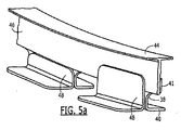
シヤタイ38ならびに内側コード44およびウェブ46は、多様な手法で構成可能である。図3に示すように、シヤタイ38は、円周方向に離間している複数の脚部40と、ウェブ46および内側コード44が取り付けられている半径方向内向きに延在する部分41とを含む。図5aに示すように、本実施形態のシヤタイ38ならびに付随する内側コード44およびウェブ46はまた、ウェブおよび/またはシヤタイの半径方向内向きに延在する部分41に取り付けられている追加の脚部48を含んでいてもよく、該追加の脚部は、シヤタイの脚部40から反対側の長手方向に延在している。追加の脚部48を取り付け具32にまた接続することにより、シヤタイ38、ウェブ46および内側コード44は、重ね継ぎの取り付け具および帯板30によりしっかりと取り付け可能である。図5aに示すように、追加の脚部48は、シヤタイ38の内向きに延在する部分41のみに接触するよう半径方向内向きに延在する比較的短い部分か、シヤタイの半径方向内向きに延在する部分とウェブ46の少なくとも一部との両方に接触するよう半径方向内向きに延在するより長い部分のいずれかを有していてもよい。追加の脚部48は、複合繊維強化材料などの複合材料またはチタンなどの金属を含むさまざまな材料から形成されていてもよい。
シヤタイ38、ウェブ46および内側コード44が一体化されている図5bにおいて別の実施形態を描写する。本実施形態において、シヤタイ38、ウェブ46および内側コード44は、背中合わせに互いに隣り合って位置している一対のC字形溝形材から形成されている。C字形溝形材は、複数の締結具などにより互いに締結されていてもよい。また、C字形溝形材は、複合繊維強化ポリマーなどの複合材料を含むさまざまな材料から形成されていてもよい。
Another embodiment is depicted in FIG. 5b where the
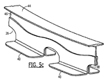
図5cにおいて、別の実施形態のシヤタイ38を描写する。示されているように、シヤタイ38は、その間にウェブを挟むようウェブ46のそれぞれ反対側に位置している2つの部分を含む。各部分は、円周方向に離間している複数の脚部40と、ウェブ46に沿って延在している半径方向内向きに延在する部分41とを含む。前に述べたように、シヤタイ38は、複合繊維強化ポリマーなどの複合材料またはチタンなどの金属を含むさまざまな材料から形成されていてもよい。
In FIG. 5c, another embodiment of a
図5dおよび図5eにおいてそれぞれ反対側からシヤタイ38のさらなる実施形態を示す。本実施形態において、強度および安定性を増大させるために、円周方向に離間している複数の脚部40と、シヤタイに取り付けられている複数の追加の脚部48とを含む、図3の実施形態で示したものと同様のシヤタイ38が設けられている。本実施形態のウェブ46および内側コード44は、シヤタイ38の半径方向内向きに延在する部分41のそれぞれ反対側に位置し、かつ、これに複数の締結具などにより接続されている2つのL字形セクションを含む。示されているように、L字形ウェブおよび内側コードのセクションは、内側コードが、長手方向に対向する方向に延在している一対の内側コードのセクションにより画定されるように背中合わせに位置している。ウェブ46および内側コード44は、複合繊維強化ポリマーなどの複合材料またはチタンなどの金属を含むさまざまな材料から形成されていてもよい。
A further embodiment of the
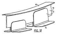
さらに、図5fおよび図5gは、シヤタイ38が複数の別個のセクションから形成されている代替の実施形態のそれぞれ反対側を示しており、ここで、複数の別個のセクションの各々は、脚部40および半径方向内向きに延在する部分41を有している。本実施形態において、シヤタイ38の別個のセクションは、ウェブ46のそれぞれ反対側に2つずつ位置していてもよく、その結果、シヤタイセクションの対が図5fおよび図5gに示す手法で複数の締結具などによりウェブに接続される。前述のように、本実施形態のシヤタイセクションは、複合繊維強化ポリマーなどの複合材料またはチタンなどの金属を含むさまざまな材料から形成されていてもよい。
Further, FIGS. 5f and 5g show opposite sides of an alternative embodiment in which the
図5hおよび図5iにおいてそれぞれ反対側から、さらに別の実施形態のシヤタイ38を示す。本実施形態において、シヤタイ38の半径方向内向きに延在する部分41は、ウェブ46および内側コード44の少なくとも一部と一体化され、かつ、これを画定している。ただし、説明的な実施形態において、ウェブ46および内側コード44はまた、シヤタイ38の半径方向内向きに延在する部分41に取り付けられているL字形溝形材により部分的に画定されてもよい。また、シヤタイ38は、上で説明したように、シヤタイの半径方向内向きに延在する部分41に取り付けられている追加の脚部48を含んでいてもよい。他の実施形態とともに上で説明したように、シヤタイ38、追加の脚部48および/またはL字形溝形材は、例えば、複合繊維強化材料などの複合材料またはチタンなどの金属を含むさまざまな材料から形成されていてもよい。
A further embodiment of a
実施形態に関わらず、シヤタイ38は、胴体セクション12の周りに円周方向に少なくとも部分的に延在しており、かつ、帯板30の上に重なっている。しかしながら、シヤタイ38は、取り付け具32上に据え付けられているので、帯板30から離間している。取り付け具32により帯板30からシヤタイ38を分離することにより、シヤタイが依然としてチタンなどの金属から形成されている場合も、取り付け具および帯板が内部により経済的に穴を形成できるようにする複合材料から形成されていてもよいように、いくつかの実施形態においては、シヤタイが取り付け具および帯板とは異なる材料から形成されていてもよい。
Regardless of the embodiment, the
図6に示すように、一対の隣り合う胴体セクション12といった一対の構造物を結合する方法も提供する。動作50において示すように、該方法はまず始めに、胴体セクション間の突合せ継手の端から端までを埋めるように胴体セクション12上に帯板30を位置付ける。次いで、取り付け具の第1および第2の長手方向に延在するセクションが帯板のそれぞれ反対側を超えて延在するように、帯板30上に1つ以上の取り付け具32を位置付けてもよい。動作52を参照のこと。これに関して、取り付け具32の位置付けは、長手方向に延在する各セクションがそれぞれの胴体セクション12の少なくとも2本の縦通材14の上に重なるように取り付け具を位置付けることを含んでいてもよい。これに関して、一実施形態の方法はまた、取り付け具32の第1および第2の長手方向に延在するセクションとそれぞれの胴体セクション12の縦通材14との間にそれぞれ第1および第2の充填材37を位置付けることを含んでいてもよい。動作54を参照のこと。充填材37は、帯板30上への取り付け具32の位置付けの前に、または、帯板上への取り付け具の位置付けに続いて位置付けてもよい。その後、取り付け具32上にシヤタイ38を位置付けてもよく、シヤタイ38、取り付け具、帯板30および胴体セクション12を複数の締結具により接続してもよい。動作56および動作58を参照のこと。上で説明したように、一実施形態の帯板30および取り付け具32は、シヤタイ38、取り付け具および胴体セクション12がチタンなどの金属から形成される複数の締結具により接続可能なように、複合材料から形成されてもよい。一実施形態において、該方法はまた、内側コードから延在し、かつ、シヤタイに接続されているウェブ46によるなどして内側コード44をシヤタイ38に接続することを含む。
A method of joining a pair of structures, such as a pair of adjacent fuselage sections 12, as shown in FIG. As shown in
上で説明したように、一実施形態のシヤタイ38は、互いに離間されている複数の脚部40を含んでいてもよい。本実施形態において、取り付け具32の位置付けは、隣接した取り付け具の間から帯板の一部が見えるように離間させて帯板30上に複数の取り付け具を位置付けることを含んでいてもよい。これに加えて、本実施形態に係る取り付け具32上へのシヤタイ38の位置付けは、シヤタイの各脚部40がそれぞれの取り付け具の中間部36上に据え付けられるように複数の取り付け具上へシヤタイを位置付けることを含んでいてもよい。
As described above, the
上で説明したように、本開示の実施形態の重ね継ぎは、胴体10などの結果として得られる構造物に十分な強度および安定性を与えつつ、より経済的な材料から形成してもよい。例えば、重ね継ぎは、チタンまたはその他の構成部品と比較して経済的でありながら、強度および安定性を提供する複合材料から形成されているある数の構成部品を含んでいてもよい。また、重ね継ぎは、チタン製構成部品のような金属における穴の穴開けおよびバリ取りとは対照的に、複合材料から形成される構成部品を貫通して締結具を収容するある数の穴を開けることを許すことなどにより、効率的にしたがって経済的に重ね継ぎを設置しやすくするような手法で提供可能である。 As explained above, the lap joints of embodiments of the present disclosure may be formed from a more economical material while providing sufficient strength and stability to the resulting structure, such as the fuselage 10. For example, a lap joint may include a number of components formed from a composite material that provides strength and stability while being economical compared to titanium or other components. In addition, lap joints have a certain number of holes that pass through components formed from composite materials and accommodate fasteners, as opposed to drilling and deburring holes in metals such as titanium components. It can be provided in such a way as to make it easier to install the lap joint efficiently and economically, for example by allowing it to be opened.
ここに記載されている本開示の多くの修正およびその他の実施形態は、前述の説明および付随する図面において提示された教示の恩恵を受けて、これらの実施形態が属する技術分野における当業者が想到するだろう。したがって、本開示は開示されている特定の実施形態に限定されるものではないこと、および、修正およびその他の実施形態は添付の請求項の範囲内に含まれるよう意図されていることは理解されるべきである。ここで特定の用語が使用されているが、それらは、包括的かつ記述的意味においてのみ用いられており、限定を目的として用いられているのではない。 Many modifications and other embodiments of the disclosure described herein will occur to those of ordinary skill in the art to which these embodiments pertain, benefiting from the teachings presented in the foregoing description and accompanying drawings. will do. Accordingly, it is to be understood that this disclosure is not limited to the particular embodiments disclosed, and that modifications and other embodiments are intended to be included within the scope of the appended claims. Should be. Although specific terms are used herein, they are used in a comprehensive and descriptive sense only and not for purposes of limitation.
Claims (12)
胴体セクション(12)の間を埋めるよう構成されている帯板(30)と、
帯板(30)上に配置された複数の取り付け具(32)と、
帯板(30)の上に重なるシヤタイ(38)であって、円周方向に互いに離間する複数の脚部(40)を含むシヤタイ(38)と、を含み、
帯板(30)とシヤタイ(38)の各脚部(40)の全てとが離間するように、複数の取り付け具(32)の一つが帯板(30)とシヤタイ(38)の複数の脚部(40)の各々との間に位置付けられ、各取り付け具(32)が、帯板(30)のそれぞれ反対側を超えて長手方向に延在している第1および第2のセクションを有し、第1および第2のセクションのそれぞれが、それぞれの胴体セクション(12)の少なくとも2本の縦通材(14)の上に重なるよう構成されている、重ね継ぎ(28)。 A lap joint (28) for joining the fuselage section (12), comprising:
A strip (30) configured to fill between the fuselage sections (12);
A plurality of fixtures (32) disposed on the strip (30);
A shear tie (38) overlying the strip (30), the shear tie (38) comprising a plurality of legs (40) spaced circumferentially from each other;
One of the plurality of attachments (32) is a plurality of legs of the strip plate (30) and the shear tie (38) so that the strip plate (30) and all the leg portions (40) of the shear tie (38) are separated from each other Each fitting (32) has first and second sections extending longitudinally beyond opposite sides of the strip (30). And a lap splice (28), wherein each of the first and second sections is configured to overlie at least two stringers (14) of a respective fuselage section (12).
間を埋めるように胴体セクション(12)上に帯板(30)を位置付けること、
各取り付け具(32)の第1および第2のセクションが帯板(30)のそれぞれ反対側を超えて長手方向に延在するように帯板(30)上に複数の取り付け具(32)を位置付けることであって、取り付け具(32)の前記位置付けが、第1および第2のセクションのそれぞれがそれぞれの胴体セクション(12)の少なくとも2本の縦通材(14)の上に重なるように取り付け具(32)を位置付けることを含む、位置付けること、
取り付け具(32)上でシヤタイ(38)を位置付けることであって、前記シヤタイ(38)は円周方向に互いに離間する複数の脚部(40)を含み、帯板(30)とシヤタイ(38)の各脚部(40)の全てとが離間するように、複数の取り付け具(32)の一つが帯板(30)とシヤタイ(38)の複数の脚部(40)の各々との間に位置付けられる、位置付けること、および、
シヤタイ(38)、取り付け具(32)、帯板(30)および胴体セクション(12)を複数の締結具により接続すること、
を含む方法。 A method for joining a fuselage section (12) comprising:
Positioning the strip (30) on the fuselage section (12) to fill the gap,
A plurality of fixtures (32) on the strip (30) such that the first and second sections of each fixture (32) extend longitudinally beyond opposite sides of the strip (30). Positioning, wherein the positioning of the fixture (32) is such that each of the first and second sections overlies at least two stringers (14) of the respective fuselage section (12). Positioning, including positioning fixture (32),
Positioning the shear tie (38) on the fixture (32), the shear tie (38) including a plurality of legs (40) spaced circumferentially from each other, the strip (30) and the shear tie (38); as with all the spacing of the legs (40) of), between each of the plurality of legs of the plurality of fixtures (32) one of which strip (30) and shear ties (38) (40) Positioned, positioning, and
Connecting the shear tie (38), the fitting (32), the strip (30) and the fuselage section (12) with a plurality of fasteners;
Including methods.
Applications Claiming Priority (3)
| Application Number | Priority Date | Filing Date | Title |
|---|---|---|---|
| US12/968,732 | 2010-12-15 | ||
| US12/968,732 US8567722B2 (en) | 2010-12-15 | 2010-12-15 | Splice and associated method for joining fuselage sections |
| PCT/US2011/059422 WO2012082254A1 (en) | 2010-12-15 | 2011-11-04 | Splice and associated method for joining fuselage sections |
Publications (3)
| Publication Number | Publication Date |
|---|---|
| JP2014500185A JP2014500185A (en) | 2014-01-09 |
| JP2014500185A5 JP2014500185A5 (en) | 2014-10-23 |
| JP6000276B2 true JP6000276B2 (en) | 2016-09-28 |
Family
ID=45044711
Family Applications (1)
| Application Number | Title | Priority Date | Filing Date |
|---|---|---|---|
| JP2013544479A Active JP6000276B2 (en) | 2010-12-15 | 2011-11-04 | Related methods for joining lap joints and fuselage sections |
Country Status (10)
| Country | Link |
|---|---|
| US (1) | US8567722B2 (en) |
| EP (1) | EP2651757B1 (en) |
| JP (1) | JP6000276B2 (en) |
| KR (1) | KR101872043B1 (en) |
| CN (2) | CN105644767B (en) |
| AU (1) | AU2011341598B2 (en) |
| CA (1) | CA2817735C (en) |
| ES (1) | ES2544051T3 (en) |
| RU (1) | RU2564561C2 (en) |
| WO (1) | WO2012082254A1 (en) |
Families Citing this family (16)
| Publication number | Priority date | Publication date | Assignee | Title |
|---|---|---|---|---|
| US7325771B2 (en) * | 2004-09-23 | 2008-02-05 | The Boeing Company | Splice joints for composite aircraft fuselages and other structures |
| FR2976916B1 (en) * | 2011-06-27 | 2013-07-26 | Airbus Operations Sas | DEVICE AND METHOD FOR ASSEMBLING TWO TRUNCONS OF AIRCRAFT FUSELAGE |
| US8740151B1 (en) * | 2012-01-03 | 2014-06-03 | The Boeing Company | Adjustable splice fitting for shimless connection of structual members |
| US8684311B2 (en) * | 2012-03-07 | 2014-04-01 | The Boeing Company | Bonded splice joint |
| US8960606B2 (en) | 2012-10-31 | 2015-02-24 | The Boeing Company | Circumference splice for joining shell structures |
| EP2781450B1 (en) * | 2013-03-19 | 2018-05-02 | Airbus Operations GmbH | System and method for interconnecting composite structures |
| EP3083395B1 (en) * | 2013-12-20 | 2021-09-08 | Saab Ab | Stiffening element and reinforced structure |
| US9527572B2 (en) | 2014-06-26 | 2016-12-27 | The Boeing Company | Elongated structures and related assemblies |
| GB2528080A (en) * | 2014-07-08 | 2016-01-13 | Airbus Operations Ltd | Structure |
| US9682429B2 (en) | 2015-04-22 | 2017-06-20 | The Boeing Company | Reaction tool and method for forming openings in an aircraft fuselage joint |
| US10392132B2 (en) | 2016-07-29 | 2019-08-27 | The Boeing Company | Curved aircraft substructure repair systems and methods |
| US10308342B2 (en) * | 2016-09-07 | 2019-06-04 | The Boeing Company | Method of repairing damage to fuselage barrel and associated apparatus and system |
| RU2655585C2 (en) * | 2016-11-22 | 2018-05-28 | Федеральное государственное унитарное предприятие "Центральный аэрогидродинамический институт имени профессора Н.Е. Жуковского" (ФГУП "ЦАГИ") | Node of the fuselage compartment with mesh and traditional constructive-power circuits |
| US11524761B2 (en) * | 2016-12-09 | 2022-12-13 | The Boeing Company | Stringer-frame intersection of aircraft body |
| US20200122816A1 (en) * | 2018-10-22 | 2020-04-23 | The Boeing Company | Bulkhead joint assembly |
| US11180238B2 (en) * | 2018-11-19 | 2021-11-23 | The Boeing Company | Shear ties for aircraft wing |
Family Cites Families (14)
| Publication number | Priority date | Publication date | Assignee | Title |
|---|---|---|---|---|
| SU1376424A1 (en) * | 1985-11-19 | 1995-10-27 | Г.Г. Демьяненко | Fuselage-to-center section joint of flying vehicle |
| US5518208A (en) * | 1993-12-28 | 1996-05-21 | The Boeing Company | Optimum aircraft body frame to body skin shear tie installation pattern for body skin/stringer circumferential splices |
| US5893534A (en) * | 1995-12-22 | 1999-04-13 | The Boeing Company | Structural apparatus and design to prevent oil can movement of webs in aircraft pressure bulkheads |
| US7159822B2 (en) * | 2004-04-06 | 2007-01-09 | The Boeing Company | Structural panels for use in aircraft fuselages and other structures |
| US7325771B2 (en) | 2004-09-23 | 2008-02-05 | The Boeing Company | Splice joints for composite aircraft fuselages and other structures |
| US7503368B2 (en) * | 2004-11-24 | 2009-03-17 | The Boeing Company | Composite sections for aircraft fuselages and other structures, and methods and systems for manufacturing such sections |
| FR2906008B1 (en) * | 2006-09-15 | 2008-11-07 | Airbus France Sa | SMOOTH CHEST AND ORBITAL JUNCTION DEVICE |
| US7787979B2 (en) * | 2007-03-14 | 2010-08-31 | The Boeing Company | Splicing fuselage sections without shims |
| DE102007018753B4 (en) * | 2007-04-20 | 2012-11-08 | Airbus Operations Gmbh | Fire protection room for aircraft passengers with the help of fuselage made of fiber-metal laminates |
| JP2008285115A (en) * | 2007-05-21 | 2008-11-27 | Mitsubishi Heavy Ind Ltd | Assembly for aircraft and its manufacturing method |
| FR2922518B1 (en) * | 2007-10-18 | 2010-04-23 | Airbus France | AIRCRAFT STRUCTURE COMPRISING STIFF STOP JUNCTIONS |
| FR2922516B1 (en) | 2007-10-18 | 2010-04-16 | Airbus France | LIGHTING OF OMEGA STIFFENERS AT THE CIRCUMFERENTIAL JUNCTION OF AN AIRCRAFT FUSELAGE |
| DE102008012252B4 (en) * | 2008-03-03 | 2014-07-31 | Airbus Operations Gmbh | Composite as well as aircraft or spacecraft with such a composite |
| FR2931720B1 (en) | 2008-06-02 | 2010-12-17 | Airbus France | METHOD FOR ORBITAL ASSEMBLY OF AIRCRAFT STRINGS IN COMPOSITE MATERIAL |
-
2010
- 2010-12-15 US US12/968,732 patent/US8567722B2/en active Active
-
2011
- 2011-11-04 AU AU2011341598A patent/AU2011341598B2/en active Active
- 2011-11-04 EP EP11788267.0A patent/EP2651757B1/en active Active
- 2011-11-04 KR KR1020137010495A patent/KR101872043B1/en active IP Right Grant
- 2011-11-04 JP JP2013544479A patent/JP6000276B2/en active Active
- 2011-11-04 CA CA2817735A patent/CA2817735C/en active Active
- 2011-11-04 CN CN201511019399.9A patent/CN105644767B/en active Active
- 2011-11-04 CN CN201180060281.4A patent/CN103261020B/en active Active
- 2011-11-04 ES ES11788267.0T patent/ES2544051T3/en active Active
- 2011-11-04 WO PCT/US2011/059422 patent/WO2012082254A1/en active Application Filing
- 2011-11-04 RU RU2013132316/11A patent/RU2564561C2/en active
Also Published As
| Publication number | Publication date |
|---|---|
| EP2651757B1 (en) | 2015-07-22 |
| CN103261020A (en) | 2013-08-21 |
| CN103261020B (en) | 2016-01-20 |
| AU2011341598A1 (en) | 2013-05-23 |
| US20120153082A1 (en) | 2012-06-21 |
| AU2011341598B2 (en) | 2016-03-10 |
| CN105644767B (en) | 2018-06-12 |
| KR20130138359A (en) | 2013-12-18 |
| CA2817735C (en) | 2016-12-06 |
| CN105644767A (en) | 2016-06-08 |
| ES2544051T3 (en) | 2015-08-27 |
| RU2013132316A (en) | 2015-01-20 |
| CA2817735A1 (en) | 2012-06-21 |
| JP2014500185A (en) | 2014-01-09 |
| WO2012082254A1 (en) | 2012-06-21 |
| EP2651757A1 (en) | 2013-10-23 |
| US8567722B2 (en) | 2013-10-29 |
| KR101872043B1 (en) | 2018-06-27 |
| RU2564561C2 (en) | 2015-10-10 |
Similar Documents
| Publication | Publication Date | Title |
|---|---|---|
| JP6000276B2 (en) | Related methods for joining lap joints and fuselage sections | |
| JP6342641B2 (en) | Circumferential splice for joining shell structures together | |
| RU2628262C2 (en) | Fuselage composite sections junction along window zone | |
| US8844871B2 (en) | Aircraft fuselage structural components and methods of making same | |
| JP5414680B2 (en) | Splicing of omega-shaped stiffeners in aircraft fuselage circumferential joints | |
| US8353479B2 (en) | Arrangement of two fuselage sections of an aircraft and a connecting structure for connecting fuselage skins | |
| AU5405501A (en) | Structural component for aircraft | |
| JP5250039B2 (en) | Aircraft structure with stiffener edge connections | |
| RU2562094C2 (en) | Stiffening element edge line | |
| JP2010531259A (en) | Reinforced profile connecting method and structural parts | |
| JP2011500417A5 (en) | ||
| WO2009137893A2 (en) | Hybrid aircraft fuselage structural components and methods of making same | |
| US7775477B2 (en) | Floor panel assembly, system, and associated method | |
| EP2662281A2 (en) | Method and system for use in assembling a fuselage | |
| JP2009539672A (en) | Aircraft fuselage structure and manufacturing method thereof | |
| US11046414B2 (en) | Wing-wingbox junction rib for an aircraft and method for producing an aircraft using such a rib | |
| JP7242197B2 (en) | Central wing box of co-cured girders and stringers | |
| JP7473318B2 (en) | Bulkhead Connection Assembly | |
| CN109555176A (en) | Swing arm, the manufacturing method of swing arm and excavator |
Legal Events
| Date | Code | Title | Description |
|---|---|---|---|
| A521 | Request for written amendment filed |
Free format text: JAPANESE INTERMEDIATE CODE: A523 Effective date: 20140904 |
|
| A621 | Written request for application examination |
Free format text: JAPANESE INTERMEDIATE CODE: A621 Effective date: 20140904 |
|
| A977 | Report on retrieval |
Free format text: JAPANESE INTERMEDIATE CODE: A971007 Effective date: 20150625 |
|
| A131 | Notification of reasons for refusal |
Free format text: JAPANESE INTERMEDIATE CODE: A131 Effective date: 20150804 |
|
| A521 | Request for written amendment filed |
Free format text: JAPANESE INTERMEDIATE CODE: A523 Effective date: 20150916 |
|
| A131 | Notification of reasons for refusal |
Free format text: JAPANESE INTERMEDIATE CODE: A131 Effective date: 20160223 |
|
| A521 | Request for written amendment filed |
Free format text: JAPANESE INTERMEDIATE CODE: A523 Effective date: 20160512 |
|
| TRDD | Decision of grant or rejection written | ||
| A01 | Written decision to grant a patent or to grant a registration (utility model) |
Free format text: JAPANESE INTERMEDIATE CODE: A01 Effective date: 20160809 |
|
| A61 | First payment of annual fees (during grant procedure) |
Free format text: JAPANESE INTERMEDIATE CODE: A61 Effective date: 20160830 |
|
| R150 | Certificate of patent or registration of utility model |
Ref document number: 6000276 Country of ref document: JP Free format text: JAPANESE INTERMEDIATE CODE: R150 |
|
| R250 | Receipt of annual fees |
Free format text: JAPANESE INTERMEDIATE CODE: R250 |
|
| R250 | Receipt of annual fees |
Free format text: JAPANESE INTERMEDIATE CODE: R250 |
|
| R250 | Receipt of annual fees |
Free format text: JAPANESE INTERMEDIATE CODE: R250 |
|
| R250 | Receipt of annual fees |
Free format text: JAPANESE INTERMEDIATE CODE: R250 |
|
| R250 | Receipt of annual fees |
Free format text: JAPANESE INTERMEDIATE CODE: R250 |