JP5999991B2 - Self-adjusting carrying strap system and method of manufacturing self-adjusting carrying strap system - Google Patents
Self-adjusting carrying strap system and method of manufacturing self-adjusting carrying strap system Download PDFInfo
- Publication number
- JP5999991B2 JP5999991B2 JP2012134525A JP2012134525A JP5999991B2 JP 5999991 B2 JP5999991 B2 JP 5999991B2 JP 2012134525 A JP2012134525 A JP 2012134525A JP 2012134525 A JP2012134525 A JP 2012134525A JP 5999991 B2 JP5999991 B2 JP 5999991B2
- Authority
- JP
- Japan
- Prior art keywords
- carrying strap
- connector plate
- bag
- passage
- bridge
- Prior art date
- Legal status (The legal status is an assumption and is not a legal conclusion. Google has not performed a legal analysis and makes no representation as to the accuracy of the status listed.)
- Active
Links
Images


Classifications
-
- A—HUMAN NECESSITIES
- A45—HAND OR TRAVELLING ARTICLES
- A45C—PURSES; LUGGAGE; HAND CARRIED BAGS
- A45C13/00—Details; Accessories
- A45C13/30—Straps; Bands
-
- A—HUMAN NECESSITIES
- A45—HAND OR TRAVELLING ARTICLES
- A45F—TRAVELLING OR CAMP EQUIPMENT: SACKS OR PACKS CARRIED ON THE BODY
- A45F3/00—Travelling or camp articles; Sacks or packs carried on the body
- A45F3/04—Sacks or packs carried on the body by means of two straps passing over the two shoulders
-
- A—HUMAN NECESSITIES
- A45—HAND OR TRAVELLING ARTICLES
- A45F—TRAVELLING OR CAMP EQUIPMENT: SACKS OR PACKS CARRIED ON THE BODY
- A45F3/00—Travelling or camp articles; Sacks or packs carried on the body
- A45F3/14—Carrying-straps; Pack-carrying harnesses
-
- A—HUMAN NECESSITIES
- A63—SPORTS; GAMES; AMUSEMENTS
- A63B—APPARATUS FOR PHYSICAL TRAINING, GYMNASTICS, SWIMMING, CLIMBING, OR FENCING; BALL GAMES; TRAINING EQUIPMENT
- A63B55/00—Bags for golf clubs; Stands for golf clubs for use on the course; Wheeled carriers specially adapted for golf bags
- A63B55/408—Releasably mounted accessories fitted outside the bag, e.g. straps or holders
-
- A—HUMAN NECESSITIES
- A45—HAND OR TRAVELLING ARTICLES
- A45F—TRAVELLING OR CAMP EQUIPMENT: SACKS OR PACKS CARRIED ON THE BODY
- A45F3/00—Travelling or camp articles; Sacks or packs carried on the body
- A45F3/14—Carrying-straps; Pack-carrying harnesses
- A45F2003/142—Carrying-straps
Description
本開示は、バッグ用、特に、ゴルフバッグ用の調整可能な持ち運び用ストラップシステムに関する。 The present disclosure relates to an adjustable carrying strap system for bags, in particular for golf bags.
多くのゴルフバッグは、略円筒形状を有し、閉じた底端部と開いた上端部を備えた、管状の繊維または皮革容器の形態をとることができ、開いた上端部を通じてゴルフクラブをゴルフバッグに出し入れする。ゴルフバックは、様々な意図された用途に、より良好に合わせるように、様々なサイズおよび材料で製造されるが、従来から2つの基本的なクラスに分類される。ゴルフバッグの第1のクラスは、手引きカートを用いて運ばれる、またはゴルフカートを用いて移送されるように設計された、通常、より大きく、より重いゴルフバッグであり、一方、ゴルフクラブバッグの第2のクラスは、プレイ中に人が持ち歩くように設計された、通常、より小さく、より軽いゴルフバッグである。 Many golf bags have a generally cylindrical shape and can take the form of a tubular fiber or leather container with a closed bottom end and an open top end, golfing a golf club through the open top end. Put it in and out of the bag. Golf bags are manufactured in a variety of sizes and materials to better fit a variety of intended applications, but are conventionally classified into two basic classes. The first class of golf bags are usually larger and heavier golf bags designed to be carried using a hand cart or transported using a golf cart, while the golf club bag's The second class is usually smaller and lighter golf bags designed to be carried around by people during play.
特に、ゴルフバッグの第2のクラスは、一般的に「キャリーバッグ」と呼ばれ、キャリーバッグは、ゴルフバッグを持ち上げて運ぶために使用できる持ち運び用ストラップ装置を使用して人が持ち歩く。多くのキャリーバッグは、ゴルフバッグを持ち上げて人の肩に当てて持ち歩くための、1つまたは2つのいずれかの持ち運び用ストラップで構成される持ち運び用ストラップ装置を有する。特に、一対の持ち運び用ストラップを有する持ち運び用ストラップ装置は、第1の持ち運び用ストラップが、バックルに沿って第2の持ち運び用ストラップと交差し、バックルが、交差した態様の両方の持ち運び用ストラップと係合するように構成することができる。バックルを使用するこの交差配置により、ゴルフバッグを持ち歩くときに、各持ち運び用ストラップを人のそれぞれの肩と係合させるのが可能になる。通常、バックルは、一方の持ち運び用ストラップが他方の持ち運び用ストラップと交差するのを可能にするのに、各持ち運び用ストラップをバックルに通さなければならないように配置された複数のスロットを画定し、これは、人がゴルフバッグを持ち歩くときに、持ち運び用ストラップが動くのを抑制するか、防止するか、または止める。したがって、人がゴルフバッグを持ち歩くときにゴルフバッグが動く場合、1つまたは複数の持ち運び用ストラップを断続的に調整することが必要なことがあり、それにより、持ち運び用ストラップを手で調整するために、人はゴルフバッグを下に置かなければならない。しかし、人がゴルフバッグを下に置き、持ち運び用ストラップに対して必要な調整を行うのに時間を割くことが必要なことがあるために、持ち運び用ストラップの手を使った調整は煩わしく、かつ時間がかかる。 In particular, the second class of golf bags is commonly referred to as “carry bags,” which are carried by a person using a carrying strap device that can be used to lift and carry the golf bag. Many carry bags have a carrying strap device that consists of either one or two carrying straps for lifting and carrying a golf bag against a person's shoulder. In particular, a carrying strap device having a pair of carrying straps includes a carrying strap in which both the first carrying strap intersects the second carrying strap along the buckle and the buckle is in a crossed manner. It can be configured to engage. This crossing arrangement using buckles allows each carrying strap to engage the person's respective shoulder when carrying the golf bag. Typically, the buckle defines a plurality of slots arranged such that each carrying strap must be passed through the buckle to allow one carrying strap to cross the other carrying strap; This suppresses, prevents or stops the carrying strap from moving when a person carries the golf bag. Thus, if a golf bag moves when a person carries the golf bag, it may be necessary to intermittently adjust one or more carrying straps, thereby adjusting the carrying straps by hand In addition, a person must put a golf bag down. However, since it may be necessary to take time to put the golf bag down and make the necessary adjustments to the carrying strap, adjustment using the hand of the carrying strap is cumbersome, and take time.
本明細書で開示する技術は、コネクタプレートで具現化することができる。コネクタプレートは、コネクタプレート本体、第1のブリッジ部分、第2のブリッジ部分を含む。コネクタプレート本体は、第1の面および第2の面を画定する。第1のブリッジ部分は第1の面から延びる。第1のブリッジは第1のチャネルを画定する。第2のブリッジ部分は第2の面から延びる。第2のブリッジ部分は第2のチャネルを画定する。第1および第2のチャネルは、バッグの第1の持ち運び用ストラップを受けるように構成された第1の通路と、バッグの第2の持ち運び用ストラップを受けるように構成された第2の通路を、第1の通路が第2の通路に対して横断する向きにあるように形成する横断空間とを画定する。 The technology disclosed in this specification can be embodied by a connector plate. The connector plate includes a connector plate body, a first bridge portion, and a second bridge portion. The connector plate body defines a first surface and a second surface. The first bridge portion extends from the first surface. The first bridge defines a first channel. The second bridge portion extends from the second surface. The second bridge portion defines a second channel. The first and second channels include a first passage configured to receive the first carrying strap of the bag and a second passage configured to receive the second carrying strap of the bag. Defining a transverse space formed such that the first passage is oriented transverse to the second passage.
上記の構成によれば、第1および第2の持ち運び用ストラップは、互いに対して自由に移動することができる。したがって、持ち運び用ストラップを容易に調整することができる。 According to said structure, the 1st and 2nd carrying strap can move freely with respect to each other. Therefore, the carrying strap can be easily adjusted.
対応する参照文字は、図面の様々な図の中の対応する要素を示す。図で使用される見出しは、特許請求の範囲を限定すると解釈すべきでない。 Corresponding reference characters indicate corresponding elements in the various figures of the drawings. The headings used in the figures should not be construed as limiting the scope of the claims.
本明細書で説明するように、自己調整式持ち運び用ストラップシステムを有するバッグ、および自己調整式持ち運び用ストラップシステムを有するかかるバッグを製造する方法は、バッグの(通常、第1のストラップおよび第2のストラップとして説明する)持ち運び用ストラップが、人の手を使う必要なしに、自動調整するのを可能にするように構成および用意される。自己調整式持ち運び用ストラップシステムは、第1のストラップを受けるように構成された2つのチャネルを有するコネクタプレートを含み、2つのチャネルはさらに、第2のストラップを受ける、第1および第2のチャネル間の横断空間を画定するように構成される。コネクタプレートは、第1および/または第2のストラップを挟み付ける、または締め付けるのを回避するように構成される。むしろ、第1および第2のストラップは、物品がバッグ内で動くか、またはバックがバッグを持ち歩いている人に対して移動するときに、ストラップがコネクタプレートに沿って、妨害なく自由に移動するのを可能にするように互いに重なる。その結果として、ストラップは手を使わずに調整することができる。バッグは、ゴルフクラブを運ぶためのゴルフバッグなどの、自己調整式持ち運び用ストラップシステムに取り付けられる任意のバッグとすることができる。 As described herein, a bag having a self-adjusting carrying strap system, and a method of manufacturing such a bag having a self-adjusting carrying strap system, can be obtained from a bag (usually a first strap and a second strap). A carrying strap (configured to be described as a strap) is constructed and prepared to allow automatic adjustment without the need for human hands. The self-adjusting carrying strap system includes a connector plate having two channels configured to receive a first strap, the two channels further receiving a second strap, first and second channels Configured to define a transverse space therebetween. The connector plate is configured to avoid pinching or tightening the first and / or second strap. Rather, the first and second straps move freely along the connector plate without obstruction when the article moves within the bag or the bag moves relative to the person carrying the bag. Overlapping each other to allow As a result, the strap can be adjusted without using hands. The bag can be any bag attached to a self-adjusting carrying strap system, such as a golf bag for carrying a golf club.
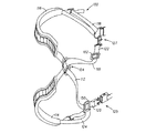
図1を参照すると、自己調整式持ち運び用ストラップシステム102の実施形態が、重い物体を収容できるバッグ115に連結されている。自己調整式持ち運び用ストラップシステム102は、コネクタプレート104に沿って、交差した態様で互いに重なる第1の持ち運び用ストラップ110および第2の持ち運び用ストラップ112を含む。コネクタプレート104は、人の手による任意の調整を必要とすることなしに、第1の持ち運び用ストラップ110および第2の持ち運び用ストラップ112が、互いに対して自己調整することを可能にするように構成されて、第1の持ち運び用ストラップ110および第2の持ち運び用ストラップ112は、図4に示すように、バッグ115の移動に応じて、第1の持ち運び用ストラップ110の軸900か、または第2の持ち運び用ストラップ112の軸902のいずれかに沿って互いに対して自由に移動する。
Referring to FIG. 1, an embodiment of a self-adjusting carrying
一部の実施形態では、人がバッグ115を持ち歩くときにクッション効果をもたらすために、第1の持ち運び用ストラップ110は、第1の肩パッド114を含むことができ、第2の持ち運び用ストラップ112は、第2の肩パッド116を含むことができる。一部の実施形態では、第1の持ち運び用ストラップ110は、人が第1の持ち運びストラップ110の長さを調整するのを可能にする第1のバックル150を含むことができ、一方、第2の持ち運び用ストラップ112は、人が第2の持ち運び用ストラップ112の長さを調整することを可能にする第2のバックル152を含むことができる。
In some embodiments, the first carrying
一部の実施形態では、第1の持ち運び用ストラップ110および第2の持ち運び用ストラップ112のそれぞれの近位部分118、122を第1のコネクタ装置127で共に係合させて、バッグ115の第1の端部156に隣接して、または第1の端部156の近傍で、第1の持ち運び用ストラップ110および第2の持ち運び用ストラップ112を連結することができる。同様に、第1の持ち運び用ストラップ110および第2の持ち運び用ストラップ112のそれぞれの遠位部分120、124を第2のコネクタ装置125で共に係合させて、バッグ115の第3の部分158に隣接して、または第2の端部158の近傍で、第1の持ち運び用ストラップ110および第2の持ち運び用ストラップ112を連結することができる。第1の持ち運び用ストラップ110および第2の持ち運び用ストラップ112の遠位部分120、124を第2のコネクタ装置125で共に係合させて、バッグ115の第2の端部157の反対側で、第1の持ち運び用ストラップ110および第2の持ち運び用ストラップ112を連結してもよい。しかし、他の実施形態では、第1の持ち運び用ストラップ110および第2の持ち運び用ストラップ112の近位部分118、122および遠位部分120、124は、さらなるコネクタ装置125、127を使用して、バッグ115に別々に連結することができる。一態様では、第1のコネクタ装置125および第2のコネクタ装置127は、リングおよびループ装置、独立バックル、フック式ファスナ装置、およびスナップ式コネクタ装置とすることができる。
In some embodiments, the
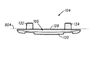
図4および図6〜11を参照して、コネクタプレート104は、既存のバッグ115に後付けで追加できるモジュール式部品である。コネクタプレート104は、第1の持ち運び用ストラップ110および第2の持ち運び用ストラップ112が、コネクタプレート104に沿って互いに重なることと、運んでいるときにバッグ115が動いた場合に、すなわち、バッグ115を運んでいる人に対してバッグ115の位置が変わったときに、第1の持ち運び用ストラップ110および第2の持ち運び用ストラップ112が、手を使わなくても、互いに対して移動することとを可能にするように構成されている。コネクタプレート110は、共同して略長方形形状を形成する第1の辺136、第2の辺138、第3の辺140、および第4の辺142を有する前面128および後面130によって画定されたコネクタ本体105を含む。一部の実施形態では、第1の辺136および第2の辺138は、実質的にまっすぐな形態を有することができ、一方、第3の辺140および第4の辺142は、全体的に湾曲した、または先細の形態を有することができる。一部の実施形態では、第1の辺136、第2の辺138、第3の辺140、および第4の辺142は、対称の形態、非対称または先細の形態、あるいは対称の形態と非対称または先細の形態との組み合わせを有することができるが、本明細書で説明する装置、製造する物品、および方法は、これに関して限定されるものではない。例えば、コネクタプレート本体105は、正方形の形態、円形の形態、だ円形の形態、および長方形の形態を有することができる。さらに示すように、コネクタプレート104は、平行な向きにある第1のブリッジ部分132および第2のブリッジ部分134を含み、第1のブリッジ部分132および第2のブリッジ部分134は、コネクタプレート本体105の、第1のブリッジ部分132と第2のブリッジ部分134との間の領域に横断空間131を画定する。第1のブリッジ部分132および第2のブリッジ部分134は、コネクタプレート本体105と係合または一体化することができる。
4 and 6 to 11, the
第1のブリッジ部分132および第2のブリッジ部分134は、平面804の上にそれぞれ第1のチャネル144および第2のチャネル146を画定し、平面804は、第1の持ち運び用ストラップ110または第2の持ち運び用ストラップ112が、第1のチャネル144および第2のチャネル146に挿入されたときに、第1の持ち運び用ストラップ110または第2の持ち運び用ストラップ112を受けるように構成されている。図6に示すように、第1のチャネル144および第2のチャネル146は、縦軸800に沿った第1の通路を画定するように一列に整列し、一方、横断空間131は、横軸802に沿った第2の通路を画定するように位置を合わされている。縦軸800に沿った第1の通路、および横軸802に沿った第2の通路は、交差する構成で互いに横断する向きに置くことができる。さらに、縦軸800に沿った第1の通路は、第1の持ち運び用ストラップ110を受けるように構成することができ、一方、横軸802に沿った第2の通路は、第2の持ち運び用ストラップ112を受けるように構成することができるので、第1の持ち運び用ストラップ110は、コネクタプレート104と係合したときに、第2の持ち運び用ストラップ112と交差し、これを覆う。別の実施形態では、縦軸800に沿った第1の通路は、第2の持ち運び用ストラップ112を受けることができ、一方、横軸802に沿った第2の通路は、第1の持ち運び用ストラップ110を受けることができる。
The
図12を参照すると、平面804は、コネクタプレート本体105の前面128に隣接して、または前面128の近傍で画定され、縦軸800に沿った第1の通路および横軸802に沿った第2の通路に対して平行な態様で延びている。第1の持ち運び用ストラップ110が、コネクタプレート104に沿って第2の持ち運び用ストラップ112と交差したときに、第1の持ち運び用ストラップ110および第2の持ち運び用ストラップ112は共に、平面804に隣接して、または平面804の近傍に配置される(図11)。
Referring to FIG. 12, the
図7および図10に示すように、コネクタプレート104は、コネクタ本体105の全長である60mmの外側長さ700と、第1の辺136および第2の辺138の長さである約41mmの内側長さ702と、第3の辺140および第4の辺142の長さである約40mmの長さ704と、第1のブリッジ部分132と第2のブリッジ部分134との間の長さである約27mmの長さ706と、第1のブリッジ部分132および第2のブリッジ部分134の長さである約27mmの長さ708とを有することができる。さらに、図10に示すように、第1のブリッジ部分132および第2のブリッジ部分134は、約7mmの高さ710を有することができる。一部の実施形態では、コネクタプレート本体105の寸法の範囲には、50mm〜70mmの長さ700と、35mm〜45mmの長さ702と、25mm〜35mmの長さ706と、5mm〜10mmの高さ710とが含まれ得る。図13では、縦軸800に沿った第1の通路および軸802に沿った第2の通路の寸法は、それぞれ第1のブリッジ部分132および第2のブリッジ部分134を受けるように設定されている。
As shown in FIGS. 7 and 10, the
バッグ115は、重い物体を担持する、または移送することができる。重い物体は、それらに限定されるものではないが、アイアンタイプのゴルフクラブ、ウッドタイプのゴルフクラブ、およびパタータイプのゴルフクラブを含むゴルフクラブ、本、サプライ、衣類、大工道具、建築設計用具、ボウリング用ボール、測量用具、コンピュータおよびコンピュータ関連アクセサリ、用紙、書類、画材、武器、靴、食糧を含む、バッグ115に収容できる任意の物品とすることができる。バッグ115は、自己調整式持ち運び用ストラップシステム102に連結されさえすれば、任意の構成または形状をとることができる。一部の実施形態では、ゴルフバッグ115は、通常、ゴルフバッグ、細長いダッフルバッグ、バックパック、ボウリングバッグ、コンピュータバッグ、リュックサック、またはスーツケースとすることができる。図1に示すように、バッグ115は、自己調整式持ち運び用ストラップシステム102に関連して第1の上側部分156、第2の中央部分157、および第3の下側部分158を画定することができる。
The
バッグ115は、皮革、合成ゴム、ネオプレン、ポリエチレン、ポリウレタン、アクリロニトリルブタジエンスチレン、樹脂、繊維材料、またはそれらの組み合わせなどの様々な材料で作製することができる。さらに、第1の持ち運び用ストラップ110および第2の持ち運び用ストラップ112も同様に、皮革、合成ゴム、ネオプレン、ポリエチレン、ポリウレタン、アクリロニトリルブタジエンスチレン、樹脂、繊維材料、またはそれらの組み合わせなどの様々な材料で作製することができる。本明細書で説明する装置、製造する物品、および方法は、これに関して限定されるものではない。
The
ゴルフバッグの実施形態が図3および図5に示され、全体として100で表されている。通常、ゴルフバッグ100は、第1の上側部分156、第2の下側部分158、および第3の中央部分157を画定する略管形の細長い本体106を含む。一実施形態では、ゴルフバッグ100は、人が持ち歩くのに適した持ち運び用バッグである。ゴルフバッグ100は、コネクタプレート104に沿って、交差した態様で互いに重なる第1の持ち運び用ストラップ110および第2の持ち運び用ストラップ112を有する自己調整式持ち運び用ストラップシステム102をさらに含む。ゴルフバッグのコネクタプレート104は、人による手を使った任意の調整を必要とすることなしに、第1の持ち運び用ストラップ110および第2の持ち運び用ストラップ112が自己調整することを可能にするように構成されて、第1の持ち運び用ストラップ110および第2の持ち運び用ストラップ112は、図5に示すように、ゴルフバッグ100の移動に応じて、第1の持ち運び用ストラップ110の軸900か、または第2の持ち運び用ストラップ112の軸902のいずれかに沿って互いに対して自由に移動する。
An embodiment of a golf bag is shown in FIGS. 3 and 5 and is generally designated 100.
一部の実施形態では、人がゴルフバッグ100を持ち歩くときにクッション効果をもたらすために、第1の持ち運び用ストラップ110は、第1の肩パッド114を含むことができ、第2の持ち運び用ストラップ112は、第2の肩パッド116を含むことができる。一部の実施形態では、第1の持ち運び用ストラップ110は、人が第1の持ち運びストラップ110の長さを調整するのを可能にする第1のバックル150を含むことができ、一方、第2の持ち運び用ストラップ112は、人が第2の持ち運び用ストラップ112の長さを調整することを可能にする第2のバックル152を含むことができる。
In some embodiments, the first carrying
一部の実施形態では、第1の持ち運び用ストラップ110および第2の持ち運び用ストラップ112のそれぞれの近位部分118、122を第1のコネクタ装置125で共に係合させて、ゴルフバッグ100の第1の上側部分156に隣接して、または第1の上側部分156の近傍で、第1の持ち運び用ストラップ110および第2の持ち運び用ストラップ112を連結することができる。同様に、第1の持ち運び用ストラップ110および第2の持ち運び用ストラップ112のそれぞれの遠位部分124、120を第2のコネクタ装置127で共に係合させて、ゴルフバッグ100の第2の下側部分158に隣接して、または第2の下側部分158の近傍で、第1の持ち運び用ストラップ110および第2の持ち運び用ストラップ112を連結することができる。しかし、他の実施形態では、第1の持ち運び用ストラップ110および第2の持ち運び用ストラップ112の近位部分118、122および遠位部分120、124は、さらなるコネクタ装置125、127を使用して、ゴルフバッグ100に別々に連結することができる。一態様では、第1のコネクタ装置125および第2のコネクタ装置127は、リングおよびループ装置、独立バックル、フック式ファスナ装置、およびスナップ式コネクタ装置とすることができる。図6〜10を参照すると、上記のように、コネクタプレート104は、第1の持ち運び用ストラップ110および第2の持ち運び用ストラップ112が、コネクタプレート104に沿って互いに重なることと、運んでいるときにゴルフバッグ100が動いた場合に、手を使わなくても互いに対して移動することとを可能にするように構成されている。
In some embodiments, the
自己調整式持ち運び用ストラップシステム102を有するバッグ115を製造する方法も図12〜14に示されている。図1および図14を参照すると、ブロック1000で、第1の上側部分156および第2の下側部分157を有する管状の細長い本体106を形成する。ブロック1002で、第1の近位部分122および第1の遠位部分124を有する第1の持ち運び用ストラップ110を形成する。ブロック1004で、第1の近位部分118および第2の遠位部分120を画定する第2の持ち運び用ストラップ112を形成する。ブロック1006で、第1のチャネル144を画定する第1のブリッジ部分132と、第2のチャネル146を画定する第2のブリッジ部分134とを含むコネクタプレート本体105を有するコネクタプレート104を形成し、コネクタプレート104において、第1のブリッジ部分132および第2のブリッジ部分134は、互いに対して平行な向きにあり、さらには、コネクタプレート本体105の前面128と同じ平面804に隣接する、または平面804の近傍にある。さらに、第1のブリッジ部分132および第2のブリッジ部分134は、第1の通路と、第1のブリッジ部分132と第2のブリッジ部分134との間で画定される横断空間131とを共同して画定し、横断空間131は、第1の通路が第2の通路に対して横断する向きにあるように第2の通路を画定する。ブロック1008で、第2の持ち運び用ストラップ112を第1の通路に沿って配置し、第1の持ち運び用ストラップ110を第1のチャネル144および第2のチャネル146に挿入し、第2の通路に沿って配置する。この交差する配置では、第1の持ち運び用ストラップ110および第2の持ち運び用ストラップ112は、横断する向きで互いに重なる。ブロック1010で、第1の持ち運び用ストラップ110の第1の近位部分122をバッグ115の上側部分156に取り付け、第1の遠位部分124をバッグ115の下側部分158に取り付ける。ブロック1012で、第2の持ち運び用ストラップ112の第2の近位部分118をバッグの上側部分156に取り付け、第2の遠位部分120をバッグ115の下側部分158に取り付ける。さらに、第1の持ち運び用ストラップ110および第2の持ち運び用ストラップ112は、互いに対して自由に移動することができるので、各それぞれの第1の持ち運び用ストラップ110および第2の持ち運び用ストラップ112は、人がバッグ115を持ち歩いているときに、バッグ115が動いた場合は常に、人の手を使わなくても自動調整する。一実施形態では、コネクタプレート本体105は、型成形加工、スタンピング加工、フライス加工、およびそれらの組み合わせを使用して形成することができる。一部の実施形態では、コネクタプレート本体105は、樹脂、金属、または複合材料から作製することができる。上記の製造方法は、図12〜14に示した自己調整式持ち運び用ストラップシステム102を有するゴルフバッグ100を製造するのに使用することができる。
A method of manufacturing a
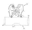
図15〜25を参照すると、202で示した、調整可能な持ち運び用ストラップシステムの他の実施形態は、第1の近位部分および第1の遠位部分を画定する第1の持ち運び用ストラップ207と、第2の近位部分および第2の遠位部分を画定する第2の持ち運び用ストラップ209とを含む。第1の持ち運び用ストラップ207および第2の持ち運び用ストラップ209は、コネクタプレート204に沿って、「X字」形状などの交差する態様で互いに重なる。一実施形態では、第1の持ち運び用ストラップ207および第2の持ち運び用ストラップ209は、実質的に「X字」形状のままであるので、この重なった配置により、第1の持ち運び用ストラップ207および第2の持ち運び用ストラップ209が、互いに対して自由に移動することが可能になる。第1の持ち運び用ストラップ207および第2の持ち運び用ストラップ209の互いに対するこの自由な移動により、コネクタプレート204が自動的に中心に位置し、第1の持ち運び用ストラップ207および第2の持ち運び用ストラップ209による単一および二重の両方の肩担持装置に対して、一様な荷重負荷が各肩に加えられるのに寄与することが可能になる。図15、図16、および図18に示すように、コネクタプレート204は、第1の持ち運び用ストラップ207および第2の持ち運び用ストラップ209が、人による手を使った調整の必要なしに、互いに対して自己調整することを可能にするように構成されて、第1の持ち運び用ストラップ207および第2の持ち運び用ストラップ209は、上側部分256、中央部分257、および下側部分258を有するバッグ215の移動に応じて、第1の持ち運び用ストラップ207の軸904か、または第2の持ち運び用ストラップ209の軸906に沿って、互いに対して自由に移動する。図27を参照すると、第2の持ち運び用ストラップ209は、下記にさらに詳細に説明するように、第2の持ち運び用ストラップ209を調整する場合に、軸916、918を境界とする方向で点908のまわりに位置を変える(turning)こともできる。
Referring to FIGS. 15-25, another embodiment of an adjustable carrying strap system, indicated at 202, includes a
図17および図19を参照すると、自己調整式持ち運び用ストラップシステム202はまた、バッグ115に対するのと同様な態様でゴルフバッグ200と係合することもできる。特に、第1の持ち運び用ストラップ207および第2の持ち運び用ストラップ209は、自己調正式持ち運び用ストラップシステム202の自動調整が行われるときに、第1の持ち運び用ストラップ207および第2の持ち運び用ストラップ209が、それぞれ軸904、軸906に沿って移動するのを可能にするように構成されたコネクタプレート204で互いに重なる。上記のように、第2の持ち運び用ストラップ209は、第2の持ち運び用ストラップ209の自動調整が行われるときに、点908のまわりに旋回することができる。
With reference to FIGS. 17 and 19, the self-adjusting
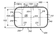
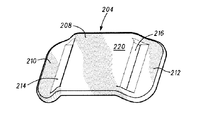
図20〜25を参照すると、コネクタプレート204は、既存のバッグ215に後付けで追加できるモジュール式部品である。コネクタプレート204は、第1の持ち運び用ストラップ207および第2の持ち運び用ストラップ209が、コネクタプレート204に沿って互いに重なることと、運んでいるときにバッグ215が動いた場合に、すなわち、バッグ215を運んでいる人に対してバッグ215が位置を変えたときに、第1の持ち運び用ストラップ207および第2の持ち運び用ストラップ209が、手を使わなくても互いに対して移動することとを可能にするように構成されている。図21および図25に示すように、コネクタプレート204は、平行な向きにある、両側の第1の隆起部分210および第2の隆起部分212とつながった中央部分208を有するコネクタプレート本体206を含み、第1の隆起部分210および第2の隆起部分212は、コネクタ本体206の、第1の隆起部分210と第2の隆起部分212との間の領域で横断空間231を画定する。コネクタプレート204は、中央部分208と第1の隆起部分210との間で画定される第1の移行部分221と、中央部分208と第2の隆起部分212との間で画定される第2の移行部分223とをさらに画定する。第1の移行部分221は、角度Bをなす平面920に実質的に合致し、一方、第2の移行部223は、同じ角度Bをなす平面922に実質的に合致している。一部の実施形態では、それぞれの平面920、または平面922と平面910との間で画定される角度Bは、鈍角、鋭角、または直角とすることができる。一実施形態では、角度Bは、30°〜130°の範囲をとることができる。コネクタプレート本体206は、共同して略長方形形状を形成する第1の辺236、第2の辺238、第3の辺240、および第4の辺242を有する前面218および後面220を画定する。一部の実施形態では、第1の辺236、第2の辺238、第3の辺240、および第4の辺242は、湾曲した、またはとがった縁部を形成することができる。一部の実施形態では、第1の辺236、第2の辺238、第3の辺240、および第4の辺242は、対称の形態、非対称の形態、非対称または先細の形態を有することができるが、本明細書で説明する装置、製造する物品、および方法は、これに関して限定されるものではない。例えば、コネクタプレート本体206は、正方形の形態、円形の形態、だ円形の形態、および長方形の形態を有することができる。
Referring to FIGS. 20-25, the
図25を参照すると、第1のスロット214および第2のスロット216は、第1の持ち運び用ストラップ207または第2の持ち運び用ストラップ209が、第1のスロット214および第2のスロット216に挿入されたときに、第1の持ち運び用ストラップ207または第2の持ち運び用ストラップ209を受けるように構成された第1の平面910の上に画定される。本明細書において、「スロット」という用語は、第1の持ち運び用ストラップ207を受けるのに十分な寸法を有する任意の細長い開口を指す。図21に示すように、第1のスロット214および第2のスロット216は、縦軸914に沿った第1の通路を画定するように並び、一方、横断空間231は、横軸915に沿った第2の通路に沿って並ぶ。軸914に沿った第1の通路、および横軸915に沿った第2の通路は、交差する構成で互いに横断する向きに置くことができる。さらに、縦軸914に沿った第1の通路は、第1の持ち運び用ストラップ207を受けるように構成することができ、一方、横軸915に沿った第2の通路は、第1の持ち運び用ストラップ207がコネクタプレート204と係合した場合に、第1の持ち運び用ストラップ207が第2の持ち運び用ストラップ209と交差し、これを覆うように第2の持ち運び用ストラップ209を受ける形で構成することができる。他の実施形態では、縦軸914に沿った第1の通路は、第2の持ち運び用ストラップ209を受けることができ、一方、横軸915の沿った第2の通路は、第1の持ち運び用ストラップ207を受けることができる。
Referring to FIG. 25, the
再度図25を参照すると、平面910は、コネクタプレート本体206の前面218に隣接して、または前面218の近傍で画定され、縦軸914に沿った第1の通路および横軸915に沿った第2の通路に対して平行な態様で延びている。第1の持ち運び用ストラップ207が、コネクタプレート204に沿って第2の持ち運び用ストラップ209と交差すると、第1の持ち運び用ストラップ207および第2の持ち運び用ストラップ209は共に、平面910に隣接して、または平面910の近傍に配置される。図18、図19、および図27を参照すると、第2の持ち運び用ストラップ209は、第1の持ち運び用ストラップ207に対して位置を変える動作250を行うことができて、第2の持ち運び用ストラップ209は、法線から+15°〜+20°と−15°〜−20°との間の範囲をとることができる角度Aをなす軸916、918間の方向に自己調整しながら移動することができる。一実施形態では、第2の持ち運び用ストラップ209の位置を変える動作は、第2の通路の長さが第2の持ち運び用ストラップ209の幅よりも長く、それによって、第2の持ち運び用ストラップ209が横方向に移動および回転することが可能になることでもたらされる。本明細書において、「位置変える(turning)」という用語は、点908のまわりか、または、第1の持ち運び用ストラップ207に対する軸916、918間に規定される任意の方向における第2の持ち運び用ストラップ209の任意のタイプの横方向動作、横断動作、旋回動作、または回転動作を指す。
Referring again to FIG. 25, the plane 910 is defined adjacent to or near the
図21、図24、および図25に示すように、コネクタプレート204は、コネクタプレート本体206の全長である約62mmの長さ1100と、第1の辺236および第3の辺240の長さである約38mmの長さ1102と、第1の隆起部分210および第2の隆起部分212の長さである約14mmの長さ1106と、第1のスロット214および第2のスロット216の長さである約30mmの長さ1108と、第1のスロット214と第2のスロット216との間の長さである約30mmの長さ1104と、第1のスロット214および第2のスロット216の高さである約3mmの長さ1110と、第1の隆起部分210および第2の隆起部分212の高さである約6mmの長さ1112とを有することができる。一実施形態では、第2の通路の幅を画定する、第1のスロット214と第2のスロット216との間の長さである長さ1104は、第1のスロット214および第2のスロット216の長さである長さ1108よりも長いので、第2の持ち運び用ストラップ209の幅は、第2の通路の幅よりも常に短く、それにより、第2の持ち運び用ストラップ209に横方向に移動するための十分な空間を付与する。一部の実施形態では、コネクタプレート本体206の寸法範囲として、長さ1100は50mm〜70mm、長さ1102は36mm〜42mm、長さ1104は28mm〜32mm、長さ1106は11mm〜17mm、長さ1108は29mm〜32mm、長さ1110は3mm〜4mm、および長さ1112は5mm〜7mmであり得る。
As shown in FIGS. 21, 24, and 25, the
自己調整式持ち運び用ストラップシステム202を有するバッグ215を製造する方法も図26〜28に示されている。図28を参照すると、ブロック1200で、上側部分256および下側部分258を有するバッグ215を形成する。ブロック1202で、第1の近位部分284および第1の遠位部分286を有する第1の持ち運び用ストラップ207を形成する。ブロック1204で、第2の近位部分280および第2の遠位部分282を有する第2の持ち運び用ストラップ209を形成する。ブロック1206で、第1のチャネル214を画定する第1の隆起部分210、および第2のチャネル216を画定する第2の隆起部分212とつながった中央部分208を画定するコネクタプレート本体206を有するコネクタプレート204を形成し、第1の隆起溝210および第2の隆起溝212は、第1の通路と、第1の通路が第2の通路に対して横断する向きにあるように第2の通路を画定する、第1の隆起部分210と第2の隆起部分212との間で画定された横断空間とに沿って整列する。ブロック1208で、第1の持ち運び用ストラップ207が第2の持ち運び用ストラップ209を覆うように、第2の持ち運び用ストラップ209を第2の通路に沿って配置し、第1の持ち運び用ストラップ207を第1の通路に沿って配置する。この交差する配置では、第1の持ち運び用ストラップ207および第2の持ち運び用ストラップ209は、横断する向きで互いに重なる。ブロック1210で、第1の持ち運び用ストラップ207の第1の近位部分284をバッグ215の上側部分256に取り付け、第1の遠位部分286をバッグ215の下側部分258に取り付ける。ブロック1212で、第2の持ち運び用ストラップ209の第2の近位部分280をバッグの上側部分256に取り付け、第2の遠位部分282をバッグ215の下側部分258に取り付ける。さらに、第1の持ち運び用ストラップ207および第2の持ち運び用ストラップ209は、互いに対して自由に移動することができるので、人がバッグ215を持ち歩いているときにバッグ215が動いた場合は常に、各それぞれの第1の持ち運び用ストラップ207および第2の持ち運び用ストラップ209は、人の手を使わなくても自動調整する。一実施形態では、コネクタプレート本体206は、型成形加工、スタンピング加工、フライス加工、およびそれらの組み合わせを使用して形成することができる。一部の実施形態では、コネクタプレート本体206は、樹脂、金属、または複合材料から作製することができる。さらに、第1の隆起部分210および第2の隆起部分212は、製造時に、中央部分208に取り付けるか、またはそれ以外に接着することができるし、あるいは、中央部分208と、第1の隆起部分210および第2の隆起部分212とが一体化した単体として形成されるようにコネクタ本体プレート206を形成することもできるが、本明細書で説明する装置、製造する物品、および方法は、これに関して限定されるものではない。上記の製造方法は、図26〜28に示した自己調整式持ち運び用ストラップシステム202を有するゴルフバッグ200を製造するのに使用することができる。
A method of manufacturing a
バッグ115と同様に、バッグ215も重い物体を担持する、または移送することができる。重い物体は、それらに限定されるものではないが、アイアンタイプのゴルフクラブ、ウッドタイプのゴルフクラブ、およびパタータイプのゴルフクラブを含むゴルフクラブ、ならびにゴルフクラブ115に関して上記した他の物体を含む、バッグ215に収容できる任意の物品とすることができる。さらに、バッグ215は、自己調整式持ち運び用ストラップシステム202に連結されさえすれば、任意の構成または形状であり得る。一部の実施形態では、バッグ215は、通常、ゴルフバッグ、リュックサック、ダッフルバッグ、またはスーツケースとすることができる。
Similar to the
ゴルフバッグ100、200は、皮革、合成ゴム、ネオプレン、ポリエチレン、ポリウレタン、アクリロニトリルブタジエンスチレン、樹脂、繊維材料、またはそれらの組み合わせなどの様々な材料で作製することができる。さらに、第1の持ち運び用ストラップ110、207および第2の持ち運び用ストラップ112、209も、皮革、合成ゴム、ネオプレン、ポリエチレン、ポリウレタン、アクリロニトリルブタジエンスチレン、樹脂、繊維材料、またはそれらの組み合わせなどの様々な材料で作製することができる。本明細書で説明した装置、製造する物品、および方法は、これに関して限定されるものではない。
特定の実施形態が、図示および説明されたが、当業者には明らかなように、本発明の趣旨および範囲から逸脱することなく様々な修正を行うことができるのは、前述から当然のことである。そのような変更および修正は、添付の特許請求の範囲で定義された本発明の範囲および教示の範囲内である。
以下に本実施例の特徴を列挙する。
(特徴1)
第1の面および第2の面を画定するコネクタプレート本体と、
前記第1の面から延び、第1のチャネルを画定する第1のブリッジ部分と、
前記第2の面から延び、第2のチャネルを画定する第2のブリッジ部分と、
を備えるコネクタプレートであって、
前記第1および第2のチャネルは、バッグの第1の持ち運び用ストラップを受ける第1の通路と、前記バッグの第2の持ち運び用ストラップを受ける第2の通路を、前記第1の通路が前記第2の通路に対して横断する向きにあるように形成する横断空間とを画定する、コネクタプレート。
(特徴2)
前記第1の通路は、前記コネクタプレートに沿った縦軸を画定し、前記第2の通路は、前記コネクタプレートに沿った横軸を画定し、前記縦軸は前記横軸に対して横断する向きにある、特徴1に記載のコネクタプレート。
(特徴3)
前記第1および第2のブリッジ部分は、実質的に互いに平行である、特徴1に記載のコネクタプレート。
(特徴4)
コネクタプレート本体を含むコネクタプレートであって、コネクタプレート本体は、
中央部分と、
前記中央部分から延び、第1のスロットを画定する第1の隆起部分と、
前記中央部分から延び、第2のスロットを画定する第2の隆起部分と、
を備え、
前記第1のスロットおよび前記第2のスロットは、バッグの第1の持ち運び用ストラップを受ける第1の通路を画定し、前記第1の隆起部分および前記第2の隆起部分は、前記バッグの第2の持ち運び用ストラップを受ける第2の通路を、前記第1の通路が前記第2の通路と交差するように形成する横断空間を画定する、コネクタプレート。
(特徴5)
前記第1の通路は、前記コネクタプレートに沿った縦軸を画定し、前記第2の通路は、前記コネクタプレートに沿った横軸を画定し、前記縦軸は前記横軸に対して横断する向きにある、特徴4に記載のコネクタプレート。
(特徴6)
前記第2の持ち運び用ストラップは、前記第1の隆起部分と前記第2の隆起部分との間に画定された前記横断空間の範囲内で位置を変えることができる、特徴5に記載のコネクタプレート。
(特徴7)
前記第1の隆起部分および前記第2の隆起部分は、実質的に互いに平行である、特徴4に記載のコネクタプレート。
(特徴8)
バッグ用の自己調整式持ち運び用ストラップシステムであって、
第1の持ち運び用ストラップと、
第2の持ち運び用ストラップと、
後面および前面を有するコネクタプレート本体を含むコネクタプレートであって、前記前面は、第1の平面に隣接する、または第1の平面近傍の第1のブリッジ部分および第2のブリッジ部分と、前記第1の平面に隣接する、または第1の平面近傍の前記第1のブリッジ部分と前記第2のブリッジ部分との間で画定される横断空間とを画定し、前記第1のブリッジ部分および前記第2のブリッジ部分は、前記第1の持ち運び用ストラップを受け、前記横断空間は、前記第1の持ち運び用ストラップが前記第2の持ち運び用ストラップを覆うように前記第2の持ち運び用ストラップを受ける、コネクタプレートと、
を備える自己調整式持ち運び用ストラップシステム。
(特徴9)
前記第1のブリッジ部分は、第1のチャネルを画定し、前記第2のブリッジ部分は、第2のチャネルを画定し、前記第1の持ち運び用ストラップは、前記コネクタプレートと係合されるときに、前記第1のチャネルおよび前記第2のチャネルに挿入される、特徴8に記載のシステム。
(特徴10)
前記第1および第2のチャネルは、前記第1の持ち運び用ストラップを受ける、縦軸に沿った第1の通路を画定するように並び、前記横断空間は、前記第2の持ち運び用ストラップを受ける、横軸に沿った第2の通路を画定する、特徴9に記載のシステム。
(特徴11)
前記バッグには、ゴルフバッグ、工具バッグ、ブックバッグ、バックパック、ダッフルバッグ、コンピュータバッグ、スーツケース、またはリュックサックのうちの少なくとも1つが含まれる、特徴8に記載のシステム。
(特徴12)
前記第1および第2の持ち運び用ストラップは、前記コネクタプレートに沿って互いに重なり、運んでいるときにゴルフバックが動いた場合に、手を使わなくても互いに対して移動する、特徴8に記載のシステム。
(特徴13)
前記コネクタプレートは、第1の辺、第2の辺、第3の辺、および第4の辺を画定し、前記第1の辺および第2の辺の長さは実質的に等しく、前記第3の辺および第4の辺の長さは実質的に等しい、特徴8に記載のシステム。
(特徴14)
前記第1の辺および第2の辺は、それぞれ前記第3の辺および第4の辺と比較して長さが長い、特徴13に記載のシステム。
(特徴15)
1つまたは複数のゴルフクラブを受け入れるチャンバと連通する開口を画定する第1の上側部分を有する細長い本体と、
前記細長い本体の第1の部分に連結されたそれぞれの第1の端部部分と、前記細長い本体の第2の部分に連結されたそれぞれの第2の端部部分とを有する第1の持ち運び用ストラップおよび第2の持ち運び用ストラップであって、前記第1の持ち運び用ストラップが前記第2の持ち運び用ストラップを覆う、第1および第2の持ち運び用ストラップと、
第1のブリッジ部分および第2のブリッジ部分を含む本体を有するコネクタプレートであって、第1のブリッジ部分および第2のブリッジ部分は、前記第1の持ち運び用ストラップを受ける第1の通路と、前記第2の持ち運び用ストラップを受ける第2の通路を、前記第1の通路が前記第2の通路に対して横断する向きにあるように形成する、前記第1および第2のブリッジ部分間に画定される横断空間とを画定する、コネクタプレートと、
を備えるバッグ。
(特徴16)
前記第1の持ち運び用ストラップは、互いに対して横断する向きで、前記第2の持ち運び用ストラップを覆う、特徴15に記載のバッグ。
(特徴17)
前記第1の通路は、前記コネクタプレートに沿った縦軸を画定し、前記第2の通路は、前記コネクタプレートに沿った横軸を画定し、前記コネクタプレートにおいて、前記縦軸は前記横軸に対して横断する向きにある、特徴15に記載のバッグ。
(特徴18)
前記第1の通路および前記第2の通路は、前記コネクタプレートの前記本体によって画定される第1の平面に隣接する、または第1の平面近傍にある、特徴15に記載のバッグ。
(特徴19)
前記第1の持ち運び用ストラップおよび前記第2の持ち運び用ストラップは、手を使わなくても自動調整可能なように、横断する向きに互いに対して移動する、特徴15に記載のバッグ。
(特徴20)
前記第1のブリッジ部分および前記第2のブリッジ部分はそれぞれ、前記第1のブリッジ部分と前記第2のブリッジ部分との間で画定される第2の長さと実質的に同じである第1の長さを画定する、特徴15に記載のバッグ。
(特徴21)
前記第1の長さおよび前記第2の長さは、それぞれ25mm〜35mmの範囲である、特徴20に記載のバッグ。
(特徴22)
前記コネクタプレートは、前記第1のブリッジ部分とつながった第1のチャネルと、前記第2のブリッジ部分とつながった第2のチャネルとを含む、特徴15に記載のバッグ。
(特徴23)
前記第1および第2のブリッジ部分は、実質的に互いに平行である、特徴15に記載のバッグ。
(特徴24)
前記第1のチャネルおよび前記第2のチャネルは縦軸に沿って一列に整列する、特徴15に記載のバッグ。
(特徴25)
前記第1の持ち運び用ストラップ、または前記第2の持ち運び用ストラップのうちの少なくとも一方は、前記細長い本体の移動に応じて自動調整するように構成される、特徴15に記載のバッグ。
(特徴26)
前記第1の持ち運び用ストラップ、または前記第2の持ち運び用ストラップのうちの少なくとも一方は肩パッドを備える、特徴15に記載のバッグ。
(特徴27)
前記第1の持ち運び用ストラップは、前記細長い本体の第1の部分と係合する近位部分と、前記細長い本体の第2の部分と係合する遠位部分とを画定し、前記第2の持ち運び用ストラップは、前記細長い本体の前記第1の部分と係合する近位部分と、前記細長い本体の前記第2の部分と係合する遠位部分とを画定し、前記第1の持ち運び用ストラップは前記第2の持ち運び用ストラップを覆う、特徴15に記載のバッグ。
(特徴28)
前記第1の持ち運び用ストラップは、前記第1のブリッジ部分および前記第2のブリッジ部分内に配置される、特徴15に記載のバッグ。
(特徴29)
調整可能な持ち運び用ストラップシステムを有するゴルフバッグを製造する方法であって、
上側部分および下側部分を有する管状の細長い本体を形成することと、
第1の近位部分および第1の遠位部分を有する細長いストラップ本体を画定する第1の持ち運び用ストラップを形成することと、
第2の近位部分および第2の遠位部分を有する第2の細長い本体を画定する第2の持ち運び用ストラップを形成することと、
第1のチャネルを画定する第1のブリッジ部分と第2のチャネルを画定する第2のブリッジ部分とを含む本体を有するコネクタプレートを形成し、第1のブリッジ部分および第2のブリッジ部分は、前記第1の持ち運び用ストラップを受けるように構成された第1の通路と、前記第2の持ち運び用ストラップを受けるように構成された第2の通路を、前記第1の通路が前記第2の通路に対して横断する向きにあるように形成する、前記第1および第2のブリッジ部分間に画定される横断空間とを共同して画定し、前記第1および第2の持ち運び用ストラップが、横断する向きで互いに重なることと、
を備える方法。
(特徴30)
前記コネクタプレートを形成することには、前記第1および第2のブリッジ部分が実質的に互いに平行であるように前記第1および第2のブリッジ部分を形成することが含まれる、特徴29に記載の方法。
(特徴31)
前記第2の持ち運び用ストラップを前記第1の通路に沿って配置し、前記第1の持ち運び用ストラップが前記第2の通路に沿って配置されるように、前記第1の持ち運び用ストラップを前記第1および第2のチャネルに挿入することをさらに備える、特徴29に記載の方法。
(特徴32)
前記第1の持ち運び用ストラップの前記第1の近位部分を前記管状の細長い本体の前記上側部分に取り付け、前記第1の遠位部分を前記管状の細長い本体の前記下側部分に取り付けることをさらに備える、特徴29に記載の方法。
(特徴33)
前記第2の持ち運び用ストラップの前記第2の近位部分を前記管状の細長い本体の前記上側部分に取り付け、前記第2の遠位部分を前記管状の細長い本体の前記下側部分に取り付けることをさらに備える、特徴29に記載の方法。
While particular embodiments have been illustrated and described, it will be appreciated from the foregoing that various modifications can be made without departing from the spirit and scope of the invention, as will be apparent to those skilled in the art. is there. Such changes and modifications are within the scope and teachings of the present invention as defined by the appended claims.
The features of this embodiment are listed below.
(Feature 1)
A connector plate body defining a first surface and a second surface;
A first bridge portion extending from the first surface and defining a first channel;
A second bridge portion extending from the second surface and defining a second channel;
A connector plate comprising:
The first and second channels include a first passage that receives a first carrying strap of a bag, a second passage that receives a second carrying strap of the bag, and the first passage includes the first passage. A connector plate defining a transverse space formed to be transverse to the second passage.
(Feature 2)
The first passage defines a longitudinal axis along the connector plate, the second passage defines a transverse axis along the connector plate, and the longitudinal axis is transverse to the transverse axis. The connector plate of
(Feature 3)
The connector plate of
(Feature 4)
A connector plate including a connector plate body, wherein the connector plate body is
The central part,
A first raised portion extending from the central portion and defining a first slot;
A second raised portion extending from the central portion and defining a second slot;
With
The first slot and the second slot define a first passage for receiving a first carrying strap of the bag, and the first raised portion and the second raised portion are the first of the bag. 2. A connector plate defining a transverse space forming a second passage for receiving two carrying straps such that the first passage intersects the second passage.
(Feature 5)
The first passage defines a longitudinal axis along the connector plate, the second passage defines a transverse axis along the connector plate, and the longitudinal axis is transverse to the transverse axis. The connector plate of claim 4 in an orientation.
(Feature 6)
6. The connector plate of claim 5, wherein the second carrying strap can be repositioned within the transverse space defined between the first raised portion and the second raised portion. .
(Feature 7)
The connector plate of claim 4, wherein the first raised portion and the second raised portion are substantially parallel to each other.
(Feature 8)
A self-adjusting carrying strap system for bags,
A first carrying strap;
A second carrying strap;
A connector plate including a connector plate body having a rear surface and a front surface, wherein the front surface is adjacent to or near the first plane, the first bridge portion and the second bridge portion, and Defining a transverse space defined between the first bridge portion and the second bridge portion adjacent to or near a first plane, the first bridge portion and the first plane Two bridge portions receive the first carrying strap and the transverse space receives the second carrying strap such that the first carrying strap covers the second carrying strap; A connector plate;
Self-adjusting carrying strap system with.
(Feature 9)
The first bridge portion defines a first channel, the second bridge portion defines a second channel, and the first carrying strap is engaged with the connector plate The system according to claim 8, wherein the system is inserted into the first channel and the second channel.
(Feature 10)
The first and second channels are arranged to define a first passage along a longitudinal axis that receives the first carrying strap, and the transverse space receives the second carrying strap. The system of claim 9, wherein the system defines a second passage along the horizontal axis.
(Feature 11)
The system of claim 8, wherein the bag includes at least one of a golf bag, a tool bag, a book bag, a backpack, a duffel bag, a computer bag, a suitcase, or a rucksack.
(Feature 12)
9. The feature of claim 8, wherein the first and second carrying straps overlap each other along the connector plate and move relative to each other without the use of a hand when the golf bag moves while carrying. System.
(Feature 13)
The connector plate defines a first side, a second side, a third side, and a fourth side, and the lengths of the first side and the second side are substantially equal, 9. The system of feature 8, wherein the length of the third side and the fourth side are substantially equal.
(Feature 14)
14. The system of feature 13, wherein the first side and the second side are longer in length than the third side and the fourth side, respectively.
(Feature 15)
An elongated body having a first upper portion defining an opening in communication with a chamber that receives one or more golf clubs;
A first carrying portion having a respective first end portion coupled to the first portion of the elongate body and a respective second end portion coupled to the second portion of the elongate body. A first and a second carrying strap, wherein the first carrying strap covers the second carrying strap; and
A connector plate having a body including a first bridge portion and a second bridge portion, the first bridge portion and the second bridge portion having a first passage for receiving the first carrying strap; Between the first and second bridge portions forming a second passage for receiving the second carrying strap so that the first passage is oriented transverse to the second passage. A connector plate defining a defined transverse space;
With a bag.
(Feature 16)
The bag of claim 15, wherein the first carrying straps cover the second carrying straps in an orientation transverse to each other.
(Feature 17)
The first passage defines a longitudinal axis along the connector plate, the second passage defines a transverse axis along the connector plate, wherein the longitudinal axis is the transverse axis. 16. The bag of feature 15, wherein the bag is in a direction transverse to the.
(Feature 18)
16. The bag of feature 15, wherein the first passage and the second passage are adjacent to or near a first plane defined by the body of the connector plate.
(Feature 19)
16. The bag of feature 15, wherein the first carrying strap and the second carrying strap move relative to one another in a transverse direction so that they can be adjusted automatically without the use of hands.
(Feature 20)
Each of the first bridge portion and the second bridge portion is substantially the same as a second length defined between the first bridge portion and the second bridge portion. The bag of feature 15, wherein the bag defines a length.
(Feature 21)
21. The bag of feature 20, wherein the first length and the second length are each in the range of 25 mm to 35 mm.
(Feature 22)
The bag of claim 15, wherein the connector plate includes a first channel connected to the first bridge portion and a second channel connected to the second bridge portion.
(Feature 23)
The bag of claim 15, wherein the first and second bridge portions are substantially parallel to each other.
(Feature 24)
The bag of claim 15, wherein the first channel and the second channel are aligned in a line along a longitudinal axis.
(Feature 25)
The bag of claim 15, wherein at least one of the first carrying strap or the second carrying strap is configured to automatically adjust in response to movement of the elongated body.
(Feature 26)
The bag of claim 15, wherein at least one of the first carrying strap or the second carrying strap comprises a shoulder pad.
(Feature 27)
The first carrying strap defines a proximal portion that engages a first portion of the elongate body and a distal portion that engages a second portion of the elongate body; The carrying strap defines a proximal portion that engages the first portion of the elongate body and a distal portion that engages the second portion of the elongate body, the first carrying strap. The bag of feature 15, wherein a strap covers the second carrying strap.
(Feature 28)
The bag of claim 15, wherein the first carrying strap is disposed within the first bridge portion and the second bridge portion.
(Feature 29)
A method of manufacturing a golf bag having an adjustable carrying strap system comprising:
Forming a tubular elongated body having an upper portion and a lower portion;
Forming a first carrying strap defining an elongated strap body having a first proximal portion and a first distal portion;
Forming a second carrying strap defining a second elongate body having a second proximal portion and a second distal portion;
Forming a connector plate having a body including a first bridge portion defining a first channel and a second bridge portion defining a second channel, wherein the first bridge portion and the second bridge portion are: A first passage configured to receive the first carrying strap; a second passage configured to receive the second carrying strap; the first passage being the second passage. Jointly defining a transverse space defined between the first and second bridge portions formed to be transverse to the passageway, the first and second carrying straps, Overlapping each other in a crossing direction,
A method comprising:
(Feature 30)
30. The feature 29, wherein forming the connector plate includes forming the first and second bridge portions such that the first and second bridge portions are substantially parallel to each other. the method of.
(Feature 31)
The second carrying strap is arranged along the first passage, and the first carrying strap is arranged so that the first carrying strap is arranged along the second passage. 30. The method of feature 29, further comprising inserting into the first and second channels.
(Feature 32)
Attaching the first proximal portion of the first carrying strap to the upper portion of the tubular elongate body and attaching the first distal portion to the lower portion of the tubular elongate body. 30. The method of feature 29, further comprising:
(Feature 33)
Attaching the second proximal portion of the second carrying strap to the upper portion of the tubular elongate body and attaching the second distal portion to the lower portion of the tubular elongate body. 30. The method of feature 29, further comprising:
Claims (29)
第1面を画定する第1の表面から外側に、かつ、前記第1の表面に対して略平行に延び、前記第1面の前記第1の表面から伸びる第1の一対の脚部を有する第1水平部と、前記第1面の前記第1表面に第1のチャネルを画定する第1のブリッジ部分と、
前記第1面を画定する前記第1の表面から外側に、かつ、前記第1の表面に対して略平行に延び、前記第1面の前記第1の表面から伸びる第2の一対の脚部を有する第2水平部と、前記第1面の前記第1表面に第2のチャネルを画定する第2のブリッジ部分と、
を備えるコネクタプレートであって、
前記第1および第2のチャネルは、実質的に直線状であり、バッグの第1の持ち運び用ストラップを受ける第1の通路と、前記バッグの第2の持ち運び用ストラップを受ける第2の通路を、前記第1の通路が前記第2の通路に対して横断する向きにあるように形成する横断空間とを画定し、
前記第1および第2のブリッジ部分は、前記コネクタプレート本体の前記周縁部よりも内側で延び、前記コネクタプレート本体の前記周縁部の一部に形成されていない、コネクタプレート。 A connector plate body surrounded by a peripheral edge and defining a first surface and a second surface;
Outwardly from the first surface you define a first plane, and extending substantially parallel to said first surface, a first pair of legs extending from the first surface of the first surface A first horizontal portion having a first bridge portion defining a first channel in the first surface of the first surface;
A second pair of legs extending outwardly from the first surface defining the first surface and substantially parallel to the first surface and extending from the first surface of the first surface A second horizontal portion having: a second bridge portion defining a second channel in the first surface of the first surface;
A connector plate comprising:
The first and second channels are substantially straight and include a first passage that receives the first carrying strap of the bag and a second passage that receives the second carrying strap of the bag. Defining a transverse space formed such that the first passage is oriented transverse to the second passage;
Said first and second bridging portion, said extending in inward from the periphery of the connector plate body, have not been formed in a part of the periphery of the connector plate body, the connector plate.
第1の持ち運び用ストラップと、
第2の持ち運び用ストラップと、
コネクタプレートを備え、
前記コネクタプレートは、
周縁部で囲まれており、後面および第1面を画定する前面を有するコネクタプレート本体と、
前記第1面を画定する前記前面から外側に延び、かつ、前記前面に対して略平行に延び、前記第1面の前記前面から伸びる第1の一対の脚部を有する第1水平部と、前記第1面の前記前面に第1のチャネルを画定する第1のブリッジ部分と、
前記第1面を画定する前記前面から外側に延び、かつ、前記前面に対して略平行に延び、前記第1面の前記前面から伸びる第2の一対の脚部を有する第2水平部と、前記第1面の前記前面に第2のチャネルを画定する第2のブリッジ部分と、
前記第1面に隣接する、または第1面近傍の前記第1のブリッジ部分と前記第2のブリッジ部分との間で画定される横断空間と、を備え、
前記第1のブリッジ部分および前記第2のブリッジ部分は、前記第1の持ち運び用ストラップを受け、
前記横断空間は、前記第1の持ち運び用ストラップが前記第2の持ち運び用ストラップを覆うように前記第2の持ち運び用ストラップを受け、
前記第1および第2のブリッジ部分は、前記コネクタプレート本体の前記周縁部よりも内側で延び、前記コネクタプレート本体の前記周縁部の一部に形成されておらず、
前記第1及び第2のチャネルは、実質的に直線状である
自己調整式持ち運び用ストラップシステム。 A self-adjusting carrying strap system for bags,
A first carrying strap;
A second carrying strap;
With connector plate,
The connector plate is
A connector plate body surrounded by a peripheral edge and having a front surface defining a rear surface and a first surface;
A first horizontal portion extending outward from the front surface defining the first surface and extending substantially parallel to the front surface and having a first pair of legs extending from the front surface of the first surface; A first bridge portion defining a first channel on the front surface of the first surface;
A second horizontal portion extending outwardly from the front surface defining the first surface and extending substantially parallel to the front surface and having a second pair of legs extending from the front surface of the first surface; A second bridge portion defining a second channel on the front surface of the first surface;
And a transverse space defined between the adjacent the first surface, or the first bridge portion and the second bridge portion of the first surface vicinity,
The first bridge portion and the second bridge portion receive the first carrying strap;
The transverse space receives the second carrying strap such that the first carrying strap covers the second carrying strap;
The first and second bridge portions extend inside the peripheral portion of the connector plate body, and are not formed on a part of the peripheral portion of the connector plate body ,
The self-adjusting carrying strap system, wherein the first and second channels are substantially straight .
前記第1および第2のチャネルは、前記第1の持ち運び用ストラップを受ける、縦軸に沿った第1の通路を画定するように並び、前記横断空間は、前記第2の持ち運び用ストラップを受ける、横軸に沿った第2の通路を画定する、請求項4又は5に記載のシステム。 The first carrying strap is inserted into the first channel and the second channel when engaged with the connector plate;
The first and second channels are arranged to define a first passage along a longitudinal axis that receives the first carrying strap, and the transverse space receives the second carrying strap. 6. A system according to claim 4 or 5, defining a second passage along the horizontal axis.
前記第1の辺および第2の辺は、それぞれ前記第3の辺および第4の辺と比較して長さが長い、請求項4から8のいずれか一項に記載のシステム。 The connector plate defines a first side, a second side, a third side, and a fourth side, and the lengths of the first side and the second side are substantially equal, The lengths of sides 3 and 4 are substantially equal;
The system according to any one of claims 4 to 8, wherein the first side and the second side are longer in length than the third side and the fourth side, respectively.
前記細長い本体の第1の部分に連結されたそれぞれの第1の端部部分と、前記細長い本体の第2の部分に連結されたそれぞれの第2の端部部分とを有する第1の持ち運び用ストラップおよび第2の持ち運び用ストラップであって、前記第1の持ち運び用ストラップが前記第2の持ち運び用ストラップを覆う、第1および第2の持ち運び用ストラップと、
第1の表面と第2の表面とを画定し、周縁部で囲まれており、第1のブリッジ部分および第2のブリッジ部分を含む本体を有するコネクタプレートであって、第1のブリッジ部分は、第1面を画定する前記第1の表面から外側に、かつ、前記第1の表面に対して略平行に延び、前記第1面の前記第1の表面から伸びる第1の一対の脚部を有する第1水平部と、前記第1面の前記第1表面に第1のチャネルを画定し、第2のブリッジ部分は、前記第1面を画定する前記第1の表面から外側に、かつ、前記第1の表面に対して略平行に延び、前記第1面の前記第1の表面から伸びる第2の一対の脚部を有する第2水平部と、前記第1面の前記第1表面に第2のチャネルを画定し、前記第1のブリッジ部分および第2のブリッジ部分は、前記第1の持ち運び用ストラップを受ける第1の通路と、前記第2の持ち運び用ストラップを受ける第2の通路を、前記第1の通路が前記第2の通路に対して横断する向きにあるように形成する、前記第1および第2のブリッジ部分間に画定される横断空間とを画定し、前記第1および第2のブリッジ部分は、前記コネクタプレート本体の前記周縁部よりも内側で延び、前記コネクタプレート本体の前記周縁部の一部に形成されていない、コネクタプレートと、
を備え、
前記第1及び第2のチャネルは、実質的に直線状であるバッグ。 An elongated body having a first upper portion defining an opening in communication with a chamber that receives one or more golf clubs;
A first carrying portion having a respective first end portion coupled to the first portion of the elongate body and a respective second end portion coupled to the second portion of the elongate body. A first and a second carrying strap, wherein the first carrying strap covers the second carrying strap; and
A connector plate having a body defining a first surface and a second surface and surrounded by a peripheral portion and including a first bridge portion and a second bridge portion, wherein the first bridge portion is A first pair of legs extending outwardly from the first surface defining the first surface and substantially parallel to the first surface and extending from the first surface of the first surface; A first horizontal portion having a first channel on the first surface of the first surface, and a second bridge portion outward from the first surface defining the first surface, and A second horizontal portion having a second pair of legs extending substantially parallel to the first surface and extending from the first surface of the first surface; and the first surface of the first surface. A second channel, wherein the first bridge portion and the second bridge portion are A first passage for receiving a carrying strap and a second passage for receiving the second carrying strap are formed such that the first passage is oriented transverse to the second passage. A transverse space defined between the first and second bridge portions, the first and second bridge portions extending inwardly of the peripheral edge of the connector plate body, and the connector plate A connector plate not formed on a part of the peripheral edge of the main body;
Equipped with a,
It said first and second channels are substantially straight der Ru bag.
上側部分および下側部分を有する管状の細長い本体を形成することと、
第1の近位部分および第1の遠位部分を有する細長いストラップ本体を画定する第1の持ち運び用ストラップを形成することと、
第2の近位部分および第2の遠位部分を有する第2の細長い本体を画定する第2の持ち運び用ストラップを形成することと、
第1の表面と第2の表面とを画定し、周縁部で囲まれており、第1のブリッジ部分と第2のブリッジ部分とを含む本体を有するコネクタプレートを形成し、第1のブリッジ部分は、第1面を画定する前記第1の表面から外側に、かつ、前記第1の表面に対して略平行に延び、前記第1面の前記第1の表面から伸びる第1の一対の脚部を有する第1水平部と、前記第1面の前記第1表面に第1のチャネルを画定し、第2のブリッジ部分は、前記第1の表面から外側に、かつ、前記第1の表面に対して略平行に延び、前記第1面の前記第1の表面から伸びる第2の一対の脚部を有する第2水平部と、前記第1面の前記第1表面に第2のチャネルを画定し、第1のブリッジ部分および第2のブリッジ部分は、前記第1の持ち運び用ストラップを受けるように構成された第1の通路と、前記第2の持ち運び用ストラップを受けるように構成された第2の通路を、前記第1の通路が前記第2の通路に対して横断する向きにあるように形成する、前記第1および第2のブリッジ部分間に画定される横断空間とを共同して画定し、前記第1および第2の持ち運び用ストラップが、横断する向きで互いに重なっており、前記第1および第2のブリッジ部分は、前記コネクタプレート本体の前記周縁部よりも内側で延び、前記コネクタプレート本体の前記周縁部の一部に形成されていないことと、
を備え、
前記第1及び第2のチャネルは、実質的に直線状である方法。 A method of manufacturing a golf bag having an adjustable carrying strap system comprising:
Forming a tubular elongated body having an upper portion and a lower portion;
Forming a first carrying strap defining an elongated strap body having a first proximal portion and a first distal portion;
Forming a second carrying strap defining a second elongate body having a second proximal portion and a second distal portion;
Forming a connector plate having a body defining a first surface and a second surface and surrounded by a peripheral portion and including a first bridge portion and a second bridge portion; Is a first pair of legs extending outwardly from the first surface defining the first surface and substantially parallel to the first surface and extending from the first surface of the first surface. A first horizontal portion having a portion, a first channel defined on the first surface of the first surface, and a second bridge portion outwardly from the first surface and the first surface. A second horizontal portion having a second pair of legs extending from the first surface of the first surface, and a second channel on the first surface of the first surface. And the first bridge portion and the second bridge portion receive the first carrying strap. A first passage configured in such a manner and a second passage configured to receive the second carrying strap, the first passage being in a direction transverse to the second passage. Jointly defining a transverse space defined between the first and second bridge portions, wherein the first and second carrying straps overlap each other in a transverse direction; The first and second bridge portions extend inside the peripheral edge of the connector plate main body, and are not formed on a part of the peripheral edge of the connector plate main body;
Equipped with a,
It said first and second channels are substantially straight der Ru method.
Applications Claiming Priority (2)
| Application Number | Priority Date | Filing Date | Title |
|---|---|---|---|
| US13/173041 | 2011-06-30 | ||
| US13/173,041 US20120267410A1 (en) | 2011-04-22 | 2011-06-30 | Self-adjustable carrying strap system and methods to manufacture self-adjustable carrying strap system |
Publications (3)
| Publication Number | Publication Date |
|---|---|
| JP2013013714A JP2013013714A (en) | 2013-01-24 |
| JP2013013714A5 JP2013013714A5 (en) | 2015-06-18 |
| JP5999991B2 true JP5999991B2 (en) | 2016-09-28 |
Family
ID=46546640
Family Applications (1)
| Application Number | Title | Priority Date | Filing Date |
|---|---|---|---|
| JP2012134525A Active JP5999991B2 (en) | 2011-06-30 | 2012-06-14 | Self-adjusting carrying strap system and method of manufacturing self-adjusting carrying strap system |
Country Status (5)
| Country | Link |
|---|---|
| JP (1) | JP5999991B2 (en) |
| KR (1) | KR101793745B1 (en) |
| CN (1) | CN102847286B (en) |
| CA (1) | CA2775931C (en) |
| GB (1) | GB2492449B (en) |
Families Citing this family (2)
| Publication number | Priority date | Publication date | Assignee | Title |
|---|---|---|---|---|
| EP3257397A1 (en) * | 2016-06-15 | 2017-12-20 | RIMOWA GmbH | Piece of luggage |
| KR102555756B1 (en) * | 2020-12-24 | 2023-07-13 | 소웅 | Strap Assembly for Transforming Fishing Chair into Carrier |
Family Cites Families (15)
| Publication number | Priority date | Publication date | Assignee | Title |
|---|---|---|---|---|
| US83387A (en) * | 1868-10-27 | Improved shoulder-brace and suspender | ||
| JPS58192933U (en) * | 1982-06-14 | 1983-12-22 | 島田 忠男 | belt adjuster |
| US4757927A (en) * | 1985-05-10 | 1988-07-19 | The Stanley Works | Holder for suspending rule clip or the like |
| SE9303146D0 (en) * | 1993-09-28 | 1993-09-28 | Peter Tegebjer | Baby Carrier |
| US5421614A (en) * | 1994-04-05 | 1995-06-06 | Zheng; Yu | Automobile seat belt adjuster |
| JP3144773B2 (en) * | 1997-12-02 | 2001-03-12 | 美津濃株式会社 | Carry device |
| US6152342A (en) * | 1998-07-20 | 2000-11-28 | Suk; Young J. | Golf bag with double strap and buckle |
| US20020145027A1 (en) * | 1999-07-21 | 2002-10-10 | Godshaw Donald E. | Low slung tool carrier |
| US6530129B1 (en) * | 2002-01-23 | 2003-03-11 | Ching-Feng Cheng | Golf bag carrying structure |
| JP2007506476A (en) * | 2003-07-16 | 2007-03-22 | モラー,ヘンリク | Detachable band group interconnection tool |
| WO2005030001A1 (en) * | 2003-09-30 | 2005-04-07 | Hans Blomgren | Shoulder strap carrier arrangement |
| US7857181B2 (en) * | 2006-02-01 | 2010-12-28 | Jerome Elliot Sacks | Multiple configuration strap apparatus for briefcases and other carrying bags |
| CN101306241B (en) * | 2007-01-10 | 2010-12-15 | 卡斯腾制造公司 | Golf bag with strap guide assembly |
| KR101016882B1 (en) * | 2009-01-08 | 2011-02-22 | 백지숙 | strap adjuster |
| CN201482099U (en) * | 2009-04-29 | 2010-05-26 | 萧昆林 | Automatic regulator for double-shoulder belt of golf bag |
-
2012
- 2012-05-03 CA CA 2775931 patent/CA2775931C/en not_active Expired - Fee Related
- 2012-05-22 GB GB1209210.2A patent/GB2492449B/en active Active
- 2012-05-29 KR KR1020120056814A patent/KR101793745B1/en active IP Right Grant
- 2012-06-14 JP JP2012134525A patent/JP5999991B2/en active Active
- 2012-06-19 CN CN201210209881.9A patent/CN102847286B/en not_active Expired - Fee Related
Also Published As
| Publication number | Publication date |
|---|---|
| GB2492449A (en) | 2013-01-02 |
| KR101793745B1 (en) | 2017-11-03 |
| GB2492449B (en) | 2017-03-29 |
| GB201209210D0 (en) | 2012-07-04 |
| KR20130004072A (en) | 2013-01-09 |
| CA2775931A1 (en) | 2012-12-30 |
| CN102847286B (en) | 2017-10-03 |
| JP2013013714A (en) | 2013-01-24 |
| CN102847286A (en) | 2013-01-02 |
| CA2775931C (en) | 2015-04-21 |
Similar Documents
| Publication | Publication Date | Title |
|---|---|---|
| US11957233B2 (en) | Self-adjustable carrying strap system and methods to manufacture self-adjustable carrying strap system | |
| US20120267410A1 (en) | Self-adjustable carrying strap system and methods to manufacture self-adjustable carrying strap system | |
| USD881515S1 (en) | Waist trainer belt | |
| US10716982B2 (en) | Systems and methods for an adjustable strap system for a golf bag | |
| US9303353B2 (en) | Basket | |
| US20140061075A1 (en) | Golf bag having adjustable characteristics | |
| EP2435143B1 (en) | Golf bag having double strap to single strap convertibility | |
| USD906671S1 (en) | Garment duffle bag | |
| US20240115915A1 (en) | Golf bag convertible strap assembly | |
| USD944006S1 (en) | Baby-changing bag | |
| USD922507S1 (en) | Golf club grip | |
| US9474332B1 (en) | Buckle apparatus to adjust strap length of a bag | |
| US9421608B2 (en) | Golf bags, top dividers for golf bags and methods of making top dividers | |
| USD982311S1 (en) | Diaper backpack | |
| USD944518S1 (en) | Handbag | |
| JP5999991B2 (en) | Self-adjusting carrying strap system and method of manufacturing self-adjusting carrying strap system | |
| USD913390S1 (en) | Golf club head | |
| USD876559S1 (en) | Weightlifting grip | |
| US20070262105A1 (en) | Dual-strap carrying structure | |
| USD947716S1 (en) | Buckle for bag | |
| JP2013013714A5 (en) | ||
| USD987755S1 (en) | Trainer golf club | |
| KR101543776B1 (en) | Knapsack with core plate | |
| US20060154738A1 (en) | Golf training device |
Legal Events
| Date | Code | Title | Description |
|---|---|---|---|
| A521 | Request for written amendment filed |
Free format text: JAPANESE INTERMEDIATE CODE: A523 Effective date: 20150421 |
|
| A621 | Written request for application examination |
Free format text: JAPANESE INTERMEDIATE CODE: A621 Effective date: 20150421 |
|
| A131 | Notification of reasons for refusal |
Free format text: JAPANESE INTERMEDIATE CODE: A131 Effective date: 20151215 |
|
| A977 | Report on retrieval |
Free format text: JAPANESE INTERMEDIATE CODE: A971007 Effective date: 20151216 |
|
| A521 | Request for written amendment filed |
Free format text: JAPANESE INTERMEDIATE CODE: A523 Effective date: 20160315 |
|
| TRDD | Decision of grant or rejection written | ||
| A01 | Written decision to grant a patent or to grant a registration (utility model) |
Free format text: JAPANESE INTERMEDIATE CODE: A01 Effective date: 20160823 |
|
| A61 | First payment of annual fees (during grant procedure) |
Free format text: JAPANESE INTERMEDIATE CODE: A61 Effective date: 20160830 |
|
| R150 | Certificate of patent or registration of utility model |
Ref document number: 5999991 Country of ref document: JP Free format text: JAPANESE INTERMEDIATE CODE: R150 |
|
| R250 | Receipt of annual fees |
Free format text: JAPANESE INTERMEDIATE CODE: R250 |
|
| R250 | Receipt of annual fees |
Free format text: JAPANESE INTERMEDIATE CODE: R250 |
|
| R250 | Receipt of annual fees |
Free format text: JAPANESE INTERMEDIATE CODE: R250 |
|
| R250 | Receipt of annual fees |
Free format text: JAPANESE INTERMEDIATE CODE: R250 |
|
| R250 | Receipt of annual fees |
Free format text: JAPANESE INTERMEDIATE CODE: R250 |