JP5998601B2 - Wrist sphygmomanometer - Google Patents
Wrist sphygmomanometer Download PDFInfo
- Publication number
- JP5998601B2 JP5998601B2 JP2012092858A JP2012092858A JP5998601B2 JP 5998601 B2 JP5998601 B2 JP 5998601B2 JP 2012092858 A JP2012092858 A JP 2012092858A JP 2012092858 A JP2012092858 A JP 2012092858A JP 5998601 B2 JP5998601 B2 JP 5998601B2
- Authority
- JP
- Japan
- Prior art keywords
- wrist
- air bag
- narrow
- sphygmomanometer
- fluid bag
- Prior art date
- Legal status (The legal status is an assumption and is not a legal conclusion. Google has not performed a legal analysis and makes no representation as to the accuracy of the status listed.)
- Active
Links
Images


Classifications
-
- A—HUMAN NECESSITIES
- A61—MEDICAL OR VETERINARY SCIENCE; HYGIENE
- A61B—DIAGNOSIS; SURGERY; IDENTIFICATION
- A61B5/00—Measuring for diagnostic purposes; Identification of persons
- A61B5/02—Detecting, measuring or recording pulse, heart rate, blood pressure or blood flow; Combined pulse/heart-rate/blood pressure determination; Evaluating a cardiovascular condition not otherwise provided for, e.g. using combinations of techniques provided for in this group with electrocardiography or electroauscultation; Heart catheters for measuring blood pressure
- A61B5/021—Measuring pressure in heart or blood vessels
- A61B5/022—Measuring pressure in heart or blood vessels by applying pressure to close blood vessels, e.g. against the skin; Ophthalmodynamometers
- A61B5/02233—Occluders specially adapted therefor
-
- A—HUMAN NECESSITIES
- A61—MEDICAL OR VETERINARY SCIENCE; HYGIENE
- A61B—DIAGNOSIS; SURGERY; IDENTIFICATION
- A61B5/00—Measuring for diagnostic purposes; Identification of persons
- A61B5/02—Detecting, measuring or recording pulse, heart rate, blood pressure or blood flow; Combined pulse/heart-rate/blood pressure determination; Evaluating a cardiovascular condition not otherwise provided for, e.g. using combinations of techniques provided for in this group with electrocardiography or electroauscultation; Heart catheters for measuring blood pressure
- A61B5/021—Measuring pressure in heart or blood vessels
- A61B5/022—Measuring pressure in heart or blood vessels by applying pressure to close blood vessels, e.g. against the skin; Ophthalmodynamometers
-
- A—HUMAN NECESSITIES
- A61—MEDICAL OR VETERINARY SCIENCE; HYGIENE
- A61B—DIAGNOSIS; SURGERY; IDENTIFICATION
- A61B5/00—Measuring for diagnostic purposes; Identification of persons
- A61B5/74—Details of notification to user or communication with user or patient ; user input means
- A61B5/742—Details of notification to user or communication with user or patient ; user input means using visual displays
-
- A—HUMAN NECESSITIES
- A61—MEDICAL OR VETERINARY SCIENCE; HYGIENE
- A61B—DIAGNOSIS; SURGERY; IDENTIFICATION
- A61B5/00—Measuring for diagnostic purposes; Identification of persons
- A61B5/74—Details of notification to user or communication with user or patient ; user input means
- A61B5/7475—User input or interface means, e.g. keyboard, pointing device, joystick
Landscapes
- Health & Medical Sciences (AREA)
- Life Sciences & Earth Sciences (AREA)
- Cardiology (AREA)
- Vascular Medicine (AREA)
- Surgery (AREA)
- Medical Informatics (AREA)
- Physics & Mathematics (AREA)
- Veterinary Medicine (AREA)
- Biophysics (AREA)
- Pathology (AREA)
- Engineering & Computer Science (AREA)
- Biomedical Technology (AREA)
- Heart & Thoracic Surgery (AREA)
- Public Health (AREA)
- Molecular Biology (AREA)
- General Health & Medical Sciences (AREA)
- Animal Behavior & Ethology (AREA)
- Physiology (AREA)
- Ophthalmology & Optometry (AREA)
- Dentistry (AREA)
- Measuring Pulse, Heart Rate, Blood Pressure Or Blood Flow (AREA)
Description
本発明は、手首式血圧計に関する。 The present invention relates to a wrist blood pressure monitor .
従来、手首式血圧計などに用いられる血圧計用カフとしては、特開平10−57323号公報(特許文献1)に開示されているように、手首に巻き付けられるカフ帯と、このカフ帯内に設けられ、手首の動脈を圧迫するために空気が供給される空気袋とを備えたものがある。 Conventionally, as a cuff for use in such a wrist blood pressure monitor, as disclosed in JP-flat 10-57323 (Patent Document 1), a cuff band wrapped around the wrist, in the cuff And an air bag supplied with air to compress the wrist artery.
この従来の血圧計用カフでは、空気袋の平面視形状を十字形状とすることにより、空気袋の容量を低減を図っている。より詳しくは、上記空気袋は、幅(手首に巻き付けられる方向に対して直交する方向の長さ)が広い幅広部と、この幅広部の巻き付け方向の両側に設けられ、上記幅広部よりも幅が狭い幅狭部とからなっている。 In this conventional cuff for a blood pressure monitor, the capacity of the air bag is reduced by making the shape of the air bag in plan view a cross shape. More specifically, the air bag is provided on a wide portion having a wide width (a length in a direction perpendicular to the direction wound around the wrist) and on both sides in the winding direction of the wide portion, and is wider than the wide portion. Has a narrow and narrow part.
上記従来の血圧計用カフでは、空気袋の平面視形状を十字形状としているため、空気袋において幅方向に延びる部分と、空気袋において巻き付け方向に延びる部分とが、互いに直角に交差している。別の言い方をすれば、上記幅広部と幅狭部が直角を成している。 In the conventional sphygmomanometer cuff, since the shape of the air bag in a plan view is a cross shape, a portion extending in the width direction of the air bag and a portion extending in the winding direction of the air bag intersect each other at right angles. . In other words, the wide part and the narrow part form a right angle.
その結果、上記空気袋に空気を供給したとき、幅広部と幅狭部の境界で応力集中が発生するので、上記直角部が破れ易いという問題がある。 As a result, when air is supplied to the air bag, stress concentration occurs at the boundary between the wide portion and the narrow portion, so that there is a problem that the right angle portion is easily broken.
そこで、本発明の課題は、流体袋の容量を低減でき、流体袋に流体を供給したときに破れを生じ難くすることができる手首式血圧計を提供することにある。 Therefore, an object of the present invention is to provide a wrist type sphygmomanometer that can reduce the capacity of a fluid bag and can hardly break when a fluid is supplied to the fluid bag.
上記課題を解決するため、本発明の手首式血圧計は、
手首の橈骨動脈と尺骨動脈との両動脈を圧迫するために流体が供給される流体袋と、
上記両動脈を有する手首の周りに上記流体袋を固定するための固定手段と
上記流体袋の外周面側に取り付けられ、血圧測定のための要素を搭載した血圧計本体と
を備え、
上記流体袋は、上記手首の周りに沿った周方向に関して、
上記血圧計本体が占める範囲を含み、上記両動脈上に配置される幅広部と、
この幅広部に連なって上記幅広部よりも幅が狭い幅狭部と
を有し、
上記幅広部の縁に連なる上記幅狭部の縁は、幅方向に対して傾斜する略直線形状となっていることを特徴としている。
In order to solve the above problems, the wrist blood pressure monitor of the present invention is
A fluid bag to which fluid is supplied to compress both the radial and ulnar arteries of the wrist ;
Fixing means for fixing the fluid bag around a wrist having both arteries;
A sphygmomanometer body mounted on the outer peripheral surface side of the fluid bag and equipped with an element for blood pressure measurement ,
The fluid bag is in a circumferential direction along the wrist,
Including a range occupied by the sphygmomanometer body, and a wide portion disposed on both arteries,
It has a narrow part narrower than the wide part connected to the wide part,
The edge of the narrow part connected to the edge of the wide part has a substantially linear shape inclined with respect to the width direction.
ここで、上記略直線形状とは、直線形状や、直線の一部(例えば端)を曲線にした形状も含むものである。 Here, the substantially linear shape includes a linear shape and a shape in which a part of the straight line (for example, an end) is curved.
上記構成によれば、上記流体袋は幅広部よりも幅が狭い幅狭部を有するので、流体袋の容量を低減できる。 According to the above configuration, since the fluid bag has the narrow portion that is narrower than the wide portion, the capacity of the fluid bag can be reduced.
また、上記幅広部の縁に連なる幅狭部の縁は、幅方向に対して傾斜する略直線形状となっているので、幅広部と幅狭部が鈍角を成すようにすることができる。したがって、上記流体袋に流体を供給したとき、幅広部と幅狭部の境界で応力集中が発生しないようにして、破れを生じ難くすることができる。 Moreover, since the edge of the narrow part connected to the edge of the wide part has a substantially linear shape inclined with respect to the width direction, the wide part and the narrow part can form an obtuse angle. Therefore, when a fluid is supplied to the fluid bag, stress concentration does not occur at the boundary between the wide portion and the narrow portion, thereby making it difficult to cause tearing.
一実施形態の手首式血圧計では、
上記幅狭部は、上記流体袋の幅方向に対して直交する方向の一端部または両端部に設けられている。
In one embodiment of the wrist sphygmomanometer ,
The narrow portion is provided at one end or both ends in a direction orthogonal to the width direction of the fluid bag.
上記実施形態によれば、上記流体袋の幅方向に対して直交する方向の一端部または両端部に幅狭部を設けることにより、流体袋の容量を低減しても、動脈を十分に圧迫できる。 According to the above embodiment, the artery can be sufficiently compressed even if the volume of the fluid bag is reduced by providing the narrow portion at one end or both ends in the direction orthogonal to the width direction of the fluid bag. .
一実施形態の手首式血圧計では、
上記幅狭部は、上記流体袋の幅方向に対して直交する方向の中央部に設けられている。
In one embodiment of the wrist sphygmomanometer ,
The narrow portion is provided at a central portion in a direction orthogonal to the width direction of the fluid bag.
上記実施形態によれば、上記流体袋の幅方向に対して直交する方向の中央部に幅狭部を設けていることにより、流体袋の容量をさらに低減できる。 According to the embodiment, the capacity of the fluid bag can be further reduced by providing the narrow portion at the center in the direction orthogonal to the width direction of the fluid bag.
一実施形態の手首式血圧計では、
上記流体袋には、上記流体袋内を複数の空間に仕切る仕切部が設けられている。
In one embodiment of the wrist sphygmomanometer ,
The fluid bag is provided with a partition that partitions the fluid bag into a plurality of spaces.
上記実施形態によれば、上記流体袋内を複数の空間に仕切る仕切部があるので、流体袋の容量から仕切部に対応する容量分減らすことができる。 According to the embodiment, since there is a partition portion that partitions the fluid bag into a plurality of spaces, the capacity corresponding to the partition portion can be reduced from the capacity of the fluid bag.
一実施形態の手首式血圧計では、
上記仕切部は、上記流体袋の幅方向に対して直交する方向の中央に設けられている。
In one embodiment of the wrist sphygmomanometer ,
The partition is provided at the center in the direction orthogonal to the width direction of the fluid bag.
上記実施形態によれば、上記固定手段によって流体袋を手首に固定する場合、流体袋の幅方向に対して直交する方向の中央に仕切部を設けることにより、流体袋内の複数の空間のうちの一つを尺骨動脈上に位置させると共に、流体袋内の複数の空間のうちの他の一つを橈骨動脈上に位置させることができる。したがって、上記尺骨動脈および橈骨動脈を確実に圧迫することができる。 According to the above embodiment, when the fluid bag is fixed to the wrist by the fixing means, the partition portion is provided at the center in the direction orthogonal to the width direction of the fluid bag, so that among the plurality of spaces in the fluid bag. One of them can be located on the ulnar artery and the other of the plurality of spaces in the fluid bag can be located on the radial artery. Therefore, the ulnar artery and radial artery can be reliably compressed.
一実施形態の手首式血圧計では、
上記仕切部は、上記流体袋の幅方向に対して直交する方向の中央よりも一端部側に寄るように設けられている。
In one embodiment of the wrist sphygmomanometer ,
The partition portion is provided so as to be closer to one end side than the center in the direction orthogonal to the width direction of the fluid bag.
上記実施形態によれば、上記固定手段によって流体袋を手首に固定する場合、流体袋の幅方向に対して直交する方向の中央よりも一端部側に寄るように仕切部を設けることにより、流体袋内の複数の空間のうちの一つを、流体袋内の複数の空間のうちの他の一つよりも大きくすることができる。したがって、上記流体袋内の複数の空間のうちの大きい一つを尺骨動脈上に位置させれば、橈骨動脈よりも深い位置にある尺骨動脈を適切に圧迫することができる。 According to the above embodiment, when the fluid bag is fixed to the wrist by the fixing means, the partition portion is provided so as to be closer to the one end side than the center in the direction orthogonal to the width direction of the fluid bag. One of the plurality of spaces in the bag can be larger than the other one of the plurality of spaces in the fluid bag. Therefore, if a large one of the plurality of spaces in the fluid bag is positioned on the ulnar artery, the ulnar artery at a position deeper than the radial artery can be appropriately compressed.
一実施形態の手首式血圧計では、
上記幅広部の幅方向に対して直交する方向の長さは、上記流体袋の幅方向に対して直交する方向の長さの1/2以上かつ3/4以下である。
In one embodiment of the wrist sphygmomanometer ,
The length of the wide portion in the direction orthogonal to the width direction is not less than 1/2 and not more than 3/4 of the length in the direction orthogonal to the width direction of the fluid bag.
上記実施形態によれば、上記固定手段によって流体袋を手首に固定する場合、上記幅広部の幅方向に対して直交する方向の長さは、流体袋の幅方向に対して直交する方向の長さの1/2以上かつ3/4以下であるので、尺骨動脈および橈骨動脈の一方しか圧迫できなくなるという事態を回避することができる。 According to the embodiment, when the fluid bag is fixed to the wrist by the fixing means, the length in the direction orthogonal to the width direction of the wide portion is the length in the direction orthogonal to the width direction of the fluid bag. Since it is 1/2 or more and 3/4 or less, it is possible to avoid a situation in which only one of the ulnar artery and radial artery can be compressed.
本発明の手首式血圧計は、動脈を圧迫するために流体が供給される流体袋を備え、この流体袋は、動脈上に配置される幅広部と、この幅広部に連なって幅広部よりも幅が狭い幅狭部とを有するので、流体袋の容量を低減できる。 The wrist type sphygmomanometer of the present invention includes a fluid bag to which a fluid is supplied in order to compress the artery, and the fluid bag includes a wide portion disposed on the artery, and the wide portion connected to the wide portion than the wide portion. Since it has the narrow part with a narrow width | variety, the capacity | capacitance of a fluid bag can be reduced.
また、上記幅広部の縁に連なる幅狭部の縁は、幅方向に対して傾斜する略直線形状となっているので、幅広部と幅狭部が鈍角を成すようにして、幅広部と幅狭部の境界で応力集中が発生するのを防ぐことができる。したがって、上記流体袋に流体を供給したとき、破れを生じ難くすることができる。 In addition, since the edge of the narrow part connected to the edge of the wide part has a substantially linear shape that is inclined with respect to the width direction, the wide part and the narrow part have an obtuse angle. It is possible to prevent stress concentration from occurring at the boundary of the narrow portion. Therefore, when a fluid is supplied to the fluid bag, it is possible to make it difficult to break.
以下、本発明の手首式血圧計1を図示の実施の形態により詳細に説明する。
Hereinafter, the
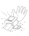
図1は、本発明の一実施形態の手首式血圧計1を手首Wに装着した状態を斜め上方から見た概略斜視図である。
FIG. 1 is a schematic perspective view of a
上記血圧計1は、血圧計本体2と、この血圧計本体2が外周面に取り付けられた血圧計用カフ3とを備え、手首W内の橈骨動脈RAおよび尺骨動脈UAを圧迫することで血圧を測定するものである。
The
上記血圧計本体2の表面には、血圧値を含む各種情報を表示する表示部21と、測定のための各種指示を入力するために操作される操作部22とを設けている。また、図示しないが、血圧計本体2は、血圧計用カフ3内の空気袋101に空気を供給するポンプや、空気袋101内の圧力(以下、「カフ圧」という)により出力値が変化する圧力センサや、ポンプおよび圧力センサなどを制御する制御装置などの要素を内蔵している。
The surface of the sphygmomanometer body 2 is provided with a
図2は、上記血圧計用カフ3を血圧計本体2側から見た概略平面図である。また、図3は、図2のIII−III線から見た概略断面図である。
FIG. 2 is a schematic plan view of the
上記血圧計用カフ3は、図2,図3に示すように、平面視形状が八角形状である空気袋101と、手首Wに空気袋101を固定するためのカフ帯102と、カフ帯102に空気袋101を接続する接続部材103とを備えている。なお、空気袋101は流体袋の一例であり、カフ帯102は固定手段の一例である。図2において、縦方向がカフ帯102、空気袋101の幅方向に相当し、横方向がカフ帯102、空気袋101の長手方向(幅方向に対して直交する方向)に相当する。カフ帯102の長手方向の両端部は符号102e,102fで表されている。
As shown in FIGS. 2 and 3, the
上記空気袋101は、カフ帯102の長手方向の端部102e側に寄るように、カフ帯102内の空間に配置されている。この空気袋101は、手首W側に配置される内シート111と、血圧計本体2側に配置される外シート112とを有している。そして、上記ポンプから空気袋101に空気を供給すると、空気袋101が膨張して、橈骨動脈RAおよび尺骨動脈UAを圧迫する。このような空気袋101は、例えば、略同形状の内シート111および外シート112を用意し、内シート111の周縁部と外シート112の周縁部とを互いに溶着することで得られる。この内シート111および外シート112の材質としては、伸縮性に富んでおり溶着後において周縁部からの漏気がないものであればどのようなものでも利用可能である。具体的には、EVA(エチレン−酢酸ビニール共重合体)、PVC(軟質塩化ビニル)、PU(ポリウレタン)、TPE−O(オレフェン系熱可塑性エラストマ)および生ゴムなどが、内シート111および外シート112の材質として挙げられる。
The
上記カフ帯102は、内シート111に対向する内布121と、外シート112に対向する外布122とを有している。手首Wにカフ帯102を巻き付けたとき、内布121の大部分が手首Wに直接接する。また、外布122および内布121の平面視形状は略長方形状であり、外布122の周縁部と内布121の周縁部とを縫い合わせている。また、内布121の長手方向(手首Wにカフ帯102を巻き付ける周方向)の端部102fの外面(空気袋101側とは反対側の表面)にはポリエステル製の面ファスナ123を設けている。また、外布122の材質としては例えばポリエステル繊維などがあり、内布121の材質としては例えばポリアミドまたはポリウレタン繊維などがある。
The
上記接続部材103は、周縁部が外シート112に溶着されたベース部131と、空気袋内に空気を出し入れするための第1筒部132と、カフ圧を検出するための第2筒部133と、先端部が外布122に係止するフック部134とを有している。このベース部131、第1筒部132、第2筒部133およびフック部134が樹脂成形で一体に形成されている。また、第1筒部132および第2筒部133は、ベース部131から外布122側に向かって延びており、先端部が外布122から突出している。また、第1筒部132および第2筒部133と同様にフック部134も、ベース部131から外布122側に向かって延びており、先端部が外布122から突出しているが、先端部が屈曲して、側面視で逆L字形状となっている(図5参照)。なお、図1では、接続部材103を覆うように、血圧計本体2が取り付けられている。
The connecting
図4は、上記空気袋101を血圧計本体2側から見た概略平面図である。また、図5は、図4のV−V線から見た概略断面図である。
FIG. 4 is a schematic plan view of the
上記空気袋101は、図4,図5に示すように、血圧計本体2が占める範囲を含み、橈骨動脈RAおよび尺骨動脈UA上に配置される幅広部104と、この幅広部104の長手方向(手首Wにカフ帯102を巻き付ける周方向)の一端に連なって幅広部104よりも幅が狭い第1幅狭部105と、この幅広部104の長手方向(手首Wにカフ帯102を巻き付ける周方向)の他端に連なって幅広部104よりも幅が狭い第2幅狭部106とを有している。この空気袋101の長手方向の長さL1は例えば140mmに設定される。なお、第1幅狭部105および第2幅狭部106は、それぞれ長手方向の一端部に設けられた幅狭部の一例である。
As shown in FIGS. 4 and 5, the
上記幅広部104の平面視形状は長方形状となっている。この幅広部104の長手方向の長さL2は例えば100mmに設定される。
The planar view shape of the
上記空気袋101の長手方向の両端部を符号101e,101fで表すものとすると、上記第1幅狭部105は空気袋101の長手方向の端部101fに設けられている一方、第2幅狭部106は空気袋101の長手方向の端部101eに設けられている。第1,第2幅狭部105,106は、それぞれ、幅広部104から離れるにしたがって徐々に幅が狭くなる形状を有している。より詳しくは、第1幅狭部105および第2幅狭部106の幅広部104側の幅W1は例えば60mmに設定され、第1幅狭部105および第2幅狭部106の幅広部104側とは反対側の幅W2は例えば20mmに設定される。そして、幅広部104の縁104aに連なる第1,第2幅狭部105,106の縁105a,106aは、幅方向に対して傾斜する直線形状を呈している。また、幅広部104の縁104bに連なる第1,第2幅狭部105,106の縁105b,106bも、幅方向に対して傾斜する直線形状を呈している。すなわち、第1,第2幅狭部105,106の平面視形状は、台形を90°回転させたような形状となっている。
If the longitudinal ends of the
上記構成の血圧計用カフ3によれば、空気袋101は幅広部104よりも幅が狭い第1,第2幅狭部105,106を有するので、空気袋101の容量を低減できる。したがって、上記ポンプを小型化して、血圧計1の小型化や薄型化を実現できる。
According to the
また、上記幅広部104の縁104a,104bに連なる第1,第2幅狭部105,106の縁105a,105b,106a,106bは、幅方向に対して傾斜する直線形状となっている。これにより、幅広部104の縁104aと第1,第2幅狭部105,106の縁105a,106aとが鈍角を成すと共に、幅広部104の縁104bと第1,第2幅狭部105,106の縁105b,106bとが鈍角を成す。したがって、空気袋101に空気を供給したとき、幅広部104と第1,第2幅狭部105,106の境界で応力集中が発生しないようにして、空気袋101が簡単に破れないようにすることができる。
Further, the
また、上記空気袋101の長手方向の一端部に第1幅狭部105を設けていると共に、空気袋101の長手方向の他端部に第2幅狭部106を設けているので、橈骨動脈RAおよび尺骨動脈UA上に幅広部104を確実に配置して、橈骨動脈RAおよび尺骨動脈UAを十分に圧迫できる。したがって、空気袋101が第1,第2幅狭部105,106を有していても、血圧の測定精度を良好にできる。
Further, since the first
上記実施形態では、動脈を圧迫するために空気が供給される空気袋101を用いていたが、動脈を圧迫するために液体が供給される液体袋を用いてもよい。
In the above embodiment, the
上記実施形態では、幅広部104の縁104a,104bに連なる第1,第2幅狭部105,106の縁105a,105b,106a,106bは、幅方向に対して傾斜する直線形状を呈していたが、直線の一部(例えば端部)を曲線にしたような形状を呈するようにしてもよい。
In the above embodiment, the
上記実施形態では、空気袋101は、カフ帯で覆われて被測定部に接触しないようになっていたが、被測定部に接触するようにしてもよい。
In the above embodiment, the
上記実施形態において、幅広部104の長手方向の長さL2は、空気袋101の長手方向の長さL1の1/2以上かつ3/4以下とするのが好ましい。すなわち、上記L2は1/2L1〜3/4L1の範囲内に設定するのが望ましい。このように設定した場合、尺骨動脈UAおよび橈骨動脈RAの一方しか圧迫できなくなるという事態を回避することができる。
In the above embodiment, the length L2 in the longitudinal direction of the
上記実施形態では、血圧計用カフは、図4に示す空気袋101を有していたが、図6に示す空気袋201を有してもよい。
In the above embodiment, the cuff for a blood pressure monitor has the
上記空気袋201の長手方向の両端部を符号201e,201fで表すものとすると、上記空気袋201は、空気袋101と同様に、長手方向の端部201fに第1幅狭部105を有すると共に、長手方向の端部201eに第2幅狭部106を有している。また、空気袋201の長手方向の中央部には第3,第4幅狭部207,208を設けている。そして、第1幅狭部105と第3幅狭部207の間には第1幅広部209を設け、第2幅狭部106と第4幅狭部208の間には第2幅広部210を設けている。この第1,第2幅広部209,210は、第1幅狭部105、第2幅狭部106、第3幅狭部207および第4幅狭部208よりも幅が広くなっている。より詳しくは、第1幅狭部105は第1幅広部209の長手方向の一端に連なって第1幅広部209から離れるにしたがって徐々に幅狭くなっている。また、第2幅狭部106は第2幅広部210の長手方向の他端に連なって第2幅広部210から離れるにしたがって徐々に幅狭くなっている。また、第3幅狭部207は第1幅広部209の長手方向の他端に連なって第1幅広部209から離れるにしたがって徐々に幅狭くなっている。また、第4幅狭部208は第2幅広部210の長手方向の一端に連なって第2幅広部210から離れるにしたがって徐々に幅狭くなっている。なお、第3,第4幅狭部207,208は、それぞれ長手方向の中央部に設けられた幅狭部の一例である。
Assuming that both ends of the
また、上記空気袋201は、略同形状の内シート211および外シート212を用意し、内シート211の周縁部と外シート212の周縁部とを互いに溶着することで得られる。この内シート211および外シート212の材質は内シート111および外シート112の材質と同じである。
The
このような空気袋201は、空気袋101よりも、容量を低減できる。その上、尺骨動脈UA上に第1幅広部209を配置すると共に、橈骨動脈RA上に第2幅広部210を配置して、橈骨動脈RAおよび尺骨動脈UAを十分に圧迫できる。
Such an
上記実施形態では、血圧計用カフは、図4に示す空気袋101を有していたが、図7に示す空気袋301を有してもよい。
In the above embodiment, the cuff for a blood pressure monitor has the
上記空気袋301の長手方向の両端部を符号301e,301fで表すものとすると、上記空気袋301は、空気袋101と同様に、長手方向の端部301fに第1幅狭部105を有すると共に、長手方向の端部301eに第2幅狭部106を有している。また、空気袋301は、第1幅狭部105と第2幅狭部106の間に幅広部304を有している。この幅広部304は第1,第2幅狭部105,106よりも幅が広くなっている。また、幅広部304には、空気袋301内を複数の空間に仕切る第1,第2溶着部341,342を設けている。この第1,第2溶着部341,342は空気袋301の長手方向の中央に位置し、第1溶着部341と第2溶着部342の間では予め設定された間隔が空いている。また、空気袋301内の第1幅狭部105側の空間と、空気袋301内の第2幅狭部106側の空間とは、第1溶着部341と第2溶着部342の間を介して連通している。また、第1,第2溶着部341,342において、長さL3は例えば10mmに設定し、幅W3は例えば5mmに設定する。なお、第1,第2溶着部341,342は仕切部の一例である。
Assuming that both end portions in the longitudinal direction of the
また、上記空気袋301は、略同形状の内シート311および外シート312を用意し、内シート311の周縁部と外シート312の周縁部とを互いに溶着すると共に、内シート311の長手方向の中央部の一部と外シート312の長手方向の中央部の一部とを互いに溶着することで得られる。この内シート311および外シート312の材質は内シート111および外シート112の材質と同じである。
The
このような空気袋301は、空気袋101よりも、容量を低減できる。その上、尺骨動脈UA上に、幅広部304の第1,第2溶着部341,342に対して第1幅狭部105側の部分を配置すると共に、橈骨動脈RA上に、幅広部304の第1,第2溶着部341,342に対して第2幅狭部106側の部分を配置することにより、橈骨動脈RAおよび尺骨動脈UAを十分に圧迫できる。
Such an
また、上記第1,第2溶着部341,342の換わりに、例えばブロック状部材または板状部材を仕切部の一例として用いてもよい。このブロック状部材および板状部材は、空気袋301内に配置すると共に、内シート311および外シート312に接着してもよい。
Further, instead of the first and second welded
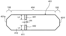
上記実施形態では、血圧計用カフは、図4に示す空気袋101を有していたが、図8に示す空気袋401を有してもよい。
In the above embodiment, the cuff for a blood pressure monitor has the
上記空気袋401の長手方向の両端部を符号401e,401fで表すものとすると、上記空気袋401は、空気袋101と同様に、長手方向の端部401fに第1幅狭部105を有すると共に、長手方向の端部401eに第2幅狭部106を有している。また、空気袋401は、第1幅狭部105と第2幅狭部106の間に幅広部404を有している。この幅広部404は第1,第2幅狭部105,106よりも幅が広くなっている。また、幅広部404には、空気袋401内を複数の空間に仕切る第1,第2溶着部441,442を設けている。この第1,第2溶着部441,442は空気袋401の長手方向の中央よりも第2幅狭部106側に寄っており、予め設定された間隔を空けて第1,第2溶着部441,442を幅方向に並べている。また、空気袋401内の第1幅狭部105側の空間と、空気袋401内の第2幅狭部106側の空間とは、第1溶着部441と第2溶着部442の間を介して連通している。また、第1,第2溶着部441,442において、長さL4は例えば10mmに設定し、幅W4は例えば5mmに設定する。なお、第1,第2溶着部441,442は仕切部の一例である。
Assuming that both end portions in the longitudinal direction of the
また、上記空気袋401は、略同形状の内シート411および外シート412を用意し、内シート411の周縁部と外シート412の周縁部とを互いに溶着すると共に、内シート411の長手方向の中央部よりも一端部側の一部と、外シート412の長手方向の中央部よりも一端部側の一部とを互いに溶着することで得られる。この内シート411および外シート412の材質は内シート111および外シート112の材質と同じである。
The
このような空気袋401は、空気袋101よりも、容量を低減できる。その上、尺骨動脈UA上に、幅広部404の第1,第2溶着部441,442に対して第1幅狭部105側の部分を配置すると共に、橈骨動脈RA上に、幅広部404の第1,第2溶着部441,442に対して第2幅狭部106側の部分を配置することにより、橈骨動脈RAおよび尺骨動脈UAを十分に圧迫できる。
Such an
また、上記幅広部404の第1,第2溶着部対して第2幅狭部106側の部分は、幅広部404の第1,第2溶着部対して第1幅狭部105側の部分よりも、容量が大きいので、橈骨動脈RAよりも深い位置にある尺骨動脈UAを適切に圧迫することができる。
Further, the portion on the second
また、上記第1,第2溶着部441,442の換わりに、例えばブロック状部材または板状部材を仕切部の一例として用いてもよい。このブロック状部材および板状部材は、空気袋401内に配置すると共に、内シート411および外シート412に接着してもよい。
Further, instead of the first and second welded
なお、図6〜図8において、図4の構成部と同一構成部は、図4における構成部と同一参照番号を付している。 6 to 8, the same components as those in FIG. 4 are given the same reference numerals as those in FIG.
また、上記接続部材103と同様の接続部材を空気袋201,301,401に取り付けてもよい。
Further, a connection member similar to the
また、上記実施形態およびその変形実施形態では、手首式血圧計1およびその変形例を左手の手首Wに装着する場合を想定して説明していたが、手首式血圧計1およびその変形例を右手の手首に装着しても、上述の作用効果と同様の作用効果は得られる。
Moreover, although the said embodiment and its modified embodiment demonstrated the case where the wrist type | mold
101,201,301,401…空気袋
102…カフ帯
103…接続部材
104,304,404…幅広部
104a,104b,105a,105b,106a,106b…縁
105…第1幅狭部
106…第2幅狭部
207…第3幅狭部
208…第4幅狭部
209…第1幅広部
210…第2幅広部
341,441…第1溶着部
342,442…第2溶着部
RA…橈骨動脈
UA…尺骨動脈
W…手首
101, 201, 301, 401 ...
Claims (7)
上記両動脈を有する手首の周りに上記流体袋を固定するための固定手段と
上記流体袋の外周面側に取り付けられ、血圧測定のための要素を搭載した血圧計本体と
を備え、
上記流体袋は、上記手首の周りに沿った周方向に関して、
上記血圧計本体が占める範囲を含み、上記両動脈上に配置される幅広部と、
この幅広部に連なって上記幅広部よりも幅が狭い幅狭部と
を有し、
上記幅広部の縁に連なる上記幅狭部の縁は、幅方向に対して傾斜する略直線形状となっていることを特徴とする手首式血圧計。 A fluid bag to which fluid is supplied to compress both the radial and ulnar arteries of the wrist ;
Fixing means for fixing the fluid bag around a wrist having both arteries;
A sphygmomanometer body mounted on the outer peripheral surface side of the fluid bag and equipped with an element for blood pressure measurement ,
The fluid bag is in a circumferential direction along the wrist,
Including a range occupied by the sphygmomanometer body, and a wide portion disposed on both arteries,
It has a narrow part narrower than the wide part connected to the wide part,
The wrist sphygmomanometer , wherein an edge of the narrow part connected to an edge of the wide part has a substantially linear shape inclined with respect to the width direction.
上記幅狭部は、上記流体袋の幅方向に対して直交する方向の一端部または両端部に設けられていることを特徴とする手首式血圧計。 The wrist sphygmomanometer according to claim 1,
The wrist sphygmomanometer , wherein the narrow portion is provided at one or both ends in a direction orthogonal to the width direction of the fluid bag.
上記幅狭部は、上記流体袋の幅方向に対して直交する方向の中央部に設けられていることを特徴とする手首式血圧計。 The wrist sphygmomanometer according to claim 1 or 2,
The wrist sphygmomanometer , wherein the narrow portion is provided at a central portion in a direction orthogonal to the width direction of the fluid bag.
上記流体袋には、上記流体袋内を複数の空間に仕切る仕切部が設けられていることを特徴とする手首式血圧計。 The wrist sphygmomanometer according to any one of claims 1 to 3,
The wrist sphygmomanometer , wherein the fluid bag is provided with a partition portion that partitions the fluid bag into a plurality of spaces.
上記仕切部は、上記流体袋の幅方向に対して直交する方向の中央に設けられていることを特徴とする手首式血圧計。 The wrist sphygmomanometer according to claim 4,
The wrist sphygmomanometer , wherein the partition portion is provided at the center in a direction orthogonal to the width direction of the fluid bag.
上記仕切部は、上記流体袋の幅方向に対して直交する方向の中央よりも一端部側に寄るように設けられていることを特徴とする手首式血圧計。 The wrist sphygmomanometer according to claim 4,
The wrist sphygmomanometer , wherein the partition portion is provided so as to be closer to one end portion side than a center in a direction orthogonal to the width direction of the fluid bag.
上記幅広部の幅方向に対して直交する方向の長さは、上記流体袋の幅方向に対して直交する方向の長さの1/2以上かつ3/4以下であることを特徴とする手首式血圧計。 The wrist sphygmomanometer according to any one of claims 1 to 6,
The wrist having a length in a direction perpendicular to the width direction of the wide portion is ½ or more and 3/4 or less of a length in a direction perpendicular to the width direction of the fluid bag. Sphygmomanometer .
Priority Applications (5)
| Application Number | Priority Date | Filing Date | Title |
|---|---|---|---|
| JP2012092858A JP5998601B2 (en) | 2012-04-16 | 2012-04-16 | Wrist sphygmomanometer |
| US14/391,279 US9060697B2 (en) | 2012-04-16 | 2013-04-03 | Blood pressure meter cuff |
| DE201311002059 DE112013002059T5 (en) | 2012-04-16 | 2013-04-03 | Sphygmomanometer cuff |
| CN201380016071.4A CN104203087B (en) | 2012-04-16 | 2013-04-03 | Cuff for blood pressure monitor |
| PCT/JP2013/060229 WO2013157393A1 (en) | 2012-04-16 | 2013-04-03 | Blood pressure meter cuff |
Applications Claiming Priority (1)
| Application Number | Priority Date | Filing Date | Title |
|---|---|---|---|
| JP2012092858A JP5998601B2 (en) | 2012-04-16 | 2012-04-16 | Wrist sphygmomanometer |
Publications (3)
| Publication Number | Publication Date |
|---|---|
| JP2013220177A JP2013220177A (en) | 2013-10-28 |
| JP2013220177A5 JP2013220177A5 (en) | 2015-04-30 |
| JP5998601B2 true JP5998601B2 (en) | 2016-09-28 |
Family
ID=49383358
Family Applications (1)
| Application Number | Title | Priority Date | Filing Date |
|---|---|---|---|
| JP2012092858A Active JP5998601B2 (en) | 2012-04-16 | 2012-04-16 | Wrist sphygmomanometer |
Country Status (5)
| Country | Link |
|---|---|
| US (1) | US9060697B2 (en) |
| JP (1) | JP5998601B2 (en) |
| CN (1) | CN104203087B (en) |
| DE (1) | DE112013002059T5 (en) |
| WO (1) | WO2013157393A1 (en) |
Families Citing this family (11)
| Publication number | Priority date | Publication date | Assignee | Title |
|---|---|---|---|---|
| US10089443B2 (en) | 2012-05-15 | 2018-10-02 | Baxter International Inc. | Home medical device systems and methods for therapy prescription and tracking, servicing and inventory |
| JP5998601B2 (en) * | 2012-04-16 | 2016-09-28 | オムロンヘルスケア株式会社 | Wrist sphygmomanometer |
| JP6228557B2 (en) * | 2015-02-27 | 2017-11-08 | オムロンヘルスケア株式会社 | Biological information measuring device |
| JP6164309B2 (en) | 2016-01-04 | 2017-07-19 | オムロンヘルスケア株式会社 | machine |
| JP6821459B2 (en) | 2017-02-07 | 2021-01-27 | オムロン株式会社 | Bag-like structure, sphygmomanometer cuff, and sphygmomanometer |
| JP6834569B2 (en) * | 2017-02-16 | 2021-02-24 | オムロンヘルスケア株式会社 | Cuff for blood pressure information measuring device |
| JP6837881B2 (en) * | 2017-03-15 | 2021-03-03 | オムロン株式会社 | Biometric information measuring devices, methods and programs |
| US20200281486A1 (en) * | 2019-03-08 | 2020-09-10 | Angelica Raquel Johnson | Blood pressure cuff having improved comfort and safety and methods of manufacturing same |
| JP6718000B1 (en) * | 2019-06-27 | 2020-07-08 | シチズン時計株式会社 | Sphygmomanometer |
| JP6751462B1 (en) * | 2019-07-24 | 2020-09-02 | シチズン時計株式会社 | Blood pressure cuff |
| EP4327734A1 (en) * | 2022-08-23 | 2024-02-28 | Contemporary Han Cloud Co., Ltd | Tourniquet |
Family Cites Families (13)
| Publication number | Priority date | Publication date | Assignee | Title |
|---|---|---|---|---|
| JPH1057323A (en) * | 1996-08-23 | 1998-03-03 | Omron Corp | Cuff band for wrist hemomanometer |
| US6245023B1 (en) * | 1999-08-19 | 2001-06-12 | Critikon Company, Llc | Conical blood pressure cuff with rectangular bladder |
| JP3740985B2 (en) * | 2001-01-23 | 2006-02-01 | オムロンヘルスケア株式会社 | Sphygmomanometer cuff |
| JP3818220B2 (en) * | 2002-06-03 | 2006-09-06 | オムロンヘルスケア株式会社 | Wrist blood pressure monitor cuff |
| US20060135876A1 (en) * | 2003-06-27 | 2006-06-22 | Andresen Alan V | Combined ECG and sound chart report and methodology |
| US7427268B2 (en) * | 2004-02-03 | 2008-09-23 | Pharma-Smart, Llc | Ring-shaped cuff for measurement of blood pressure |
| JP4654641B2 (en) * | 2004-09-15 | 2011-03-23 | オムロンヘルスケア株式会社 | Sphygmomanometer cuff |
| JP4742576B2 (en) * | 2004-12-10 | 2011-08-10 | オムロンヘルスケア株式会社 | Sphygmomanometer cuff and sphygmomanometer equipped with the same |
| DE102007037770B4 (en) * | 2007-08-10 | 2017-01-05 | Drägerwerk AG & Co. KGaA | Blood pressure cuff for non-invasive blood pressure measurement |
| JP5082963B2 (en) * | 2008-03-19 | 2012-11-28 | オムロンヘルスケア株式会社 | Sphygmomanometer cuff and sphygmomanometer equipped with the same |
| JP5169552B2 (en) * | 2008-07-07 | 2013-03-27 | オムロンヘルスケア株式会社 | Cuff for blood pressure information measuring device and blood pressure information measuring device provided with the same |
| JP5998601B2 (en) * | 2012-04-16 | 2016-09-28 | オムロンヘルスケア株式会社 | Wrist sphygmomanometer |
| US9743847B2 (en) * | 2013-03-15 | 2017-08-29 | St. Luke Medical, Inc. | Blood pressure cuff with tapered bladder |
-
2012
- 2012-04-16 JP JP2012092858A patent/JP5998601B2/en active Active
-
2013
- 2013-04-03 WO PCT/JP2013/060229 patent/WO2013157393A1/en active Application Filing
- 2013-04-03 CN CN201380016071.4A patent/CN104203087B/en active Active
- 2013-04-03 US US14/391,279 patent/US9060697B2/en active Active
- 2013-04-03 DE DE201311002059 patent/DE112013002059T5/en active Pending
Also Published As
| Publication number | Publication date |
|---|---|
| DE112013002059T5 (en) | 2015-01-22 |
| CN104203087A (en) | 2014-12-10 |
| US9060697B2 (en) | 2015-06-23 |
| CN104203087B (en) | 2016-05-04 |
| WO2013157393A1 (en) | 2013-10-24 |
| US20150105676A1 (en) | 2015-04-16 |
| JP2013220177A (en) | 2013-10-28 |
Similar Documents
| Publication | Publication Date | Title |
|---|---|---|
| JP5998601B2 (en) | Wrist sphygmomanometer | |
| JP2013220177A5 (en) | ||
| KR100666807B1 (en) | Cuff for Blood Pressure Monitor and Blood Pressure Monitor Having the Same | |
| US10299726B2 (en) | Bodily information measurement apparatus | |
| ES2293467T3 (en) | HOSE FOR SPHIGMOMANOMETER, SPHIGMOMANOMETER, DEVICE FOR EXERCISING PRESSURE ON A LIVING BODY AND MEASURING DEVICE FOR PURCHASING INFORMATION ABOUT A LIVING BODY. | |
| JP5145930B2 (en) | Sphygmomanometer cuff and sphygmomanometer | |
| EP3360470B1 (en) | Wearable blood pressure cuff, sphygmomanometer and usage method thereof | |
| US10542895B2 (en) | Blood pressure measurement cuff and blood pressure monitor including the same | |
| EP2953528B1 (en) | Blood pressure measuring system comprising a kinking-proof shell | |
| KR20060091235A (en) | Sphygmomanometer cuff and sphygmomanometer | |
| JP3952957B2 (en) | Cuff for wrist blood pressure monitor | |
| US11272853B2 (en) | Bag-shaped structure used in a cuff for blood pressure measurement | |
| JP6051732B2 (en) | Cuff for blood pressure information measuring device and blood pressure information measuring device | |
| JP5942689B2 (en) | Channel forming member and blood pressure measuring device | |
| JP2019118418A (en) | Blood pressure measurement device | |
| US6969356B2 (en) | Inflatable cuff for blood pressure measurement | |
| JP5159549B2 (en) | Biological compression device, manufacturing method thereof, and blood pressure measurement device | |
| JP3176530U (en) | Sphygmomanometer | |
| JP7536841B2 (en) | Belt and blood pressure measuring device | |
| JP5170720B1 (en) | Biological information collection device | |
| US11304613B2 (en) | Bag-shaped structure, cuff, and blood pressure monitor | |
| JP5208655B2 (en) | Biological compression device, manufacturing method thereof, and blood pressure measurement device | |
| CN205568936U (en) | Sphygmomanometer sleeve area and wrist -watch formula electrosphygmomanometer | |
| JP3638932B2 (en) | Double cuff for blood pressure measurement | |
| US11925444B2 (en) | Blood pressure measurement device |
Legal Events
| Date | Code | Title | Description |
|---|---|---|---|
| A621 | Written request for application examination |
Free format text: JAPANESE INTERMEDIATE CODE: A621 Effective date: 20150310 |
|
| A521 | Written amendment |
Free format text: JAPANESE INTERMEDIATE CODE: A523 Effective date: 20150312 |
|
| A131 | Notification of reasons for refusal |
Free format text: JAPANESE INTERMEDIATE CODE: A131 Effective date: 20160202 |
|
| A521 | Written amendment |
Free format text: JAPANESE INTERMEDIATE CODE: A523 Effective date: 20160329 |
|
| TRDD | Decision of grant or rejection written | ||
| A01 | Written decision to grant a patent or to grant a registration (utility model) |
Free format text: JAPANESE INTERMEDIATE CODE: A01 Effective date: 20160802 |
|
| A61 | First payment of annual fees (during grant procedure) |
Free format text: JAPANESE INTERMEDIATE CODE: A61 Effective date: 20160815 |
|
| R150 | Certificate of patent or registration of utility model |
Ref document number: 5998601 Country of ref document: JP Free format text: JAPANESE INTERMEDIATE CODE: R150 |