JP5993961B2 - Video endoscope with adjustable viewing direction - Google Patents
Video endoscope with adjustable viewing direction Download PDFInfo
- Publication number
- JP5993961B2 JP5993961B2 JP2014558032A JP2014558032A JP5993961B2 JP 5993961 B2 JP5993961 B2 JP 5993961B2 JP 2014558032 A JP2014558032 A JP 2014558032A JP 2014558032 A JP2014558032 A JP 2014558032A JP 5993961 B2 JP5993961 B2 JP 5993961B2
- Authority
- JP
- Japan
- Prior art keywords
- video endoscope
- endoscope
- translation
- prism
- rotation
- Prior art date
- Legal status (The legal status is an assumption and is not a legal conclusion. Google has not performed a legal analysis and makes no representation as to the accuracy of the status listed.)
- Expired - Fee Related
Links
Images


Classifications
-
- A—HUMAN NECESSITIES
- A61—MEDICAL OR VETERINARY SCIENCE; HYGIENE
- A61B—DIAGNOSIS; SURGERY; IDENTIFICATION
- A61B1/00—Instruments for performing medical examinations of the interior of cavities or tubes of the body by visual or photographical inspection, e.g. endoscopes; Illuminating arrangements therefor
- A61B1/00163—Optical arrangements
- A61B1/00174—Optical arrangements characterised by the viewing angles
- A61B1/00183—Optical arrangements characterised by the viewing angles for variable viewing angles
-
- A—HUMAN NECESSITIES
- A61—MEDICAL OR VETERINARY SCIENCE; HYGIENE
- A61B—DIAGNOSIS; SURGERY; IDENTIFICATION
- A61B1/00—Instruments for performing medical examinations of the interior of cavities or tubes of the body by visual or photographical inspection, e.g. endoscopes; Illuminating arrangements therefor
- A61B1/00002—Operational features of endoscopes
- A61B1/00004—Operational features of endoscopes characterised by electronic signal processing
- A61B1/00006—Operational features of endoscopes characterised by electronic signal processing of control signals
-
- A—HUMAN NECESSITIES
- A61—MEDICAL OR VETERINARY SCIENCE; HYGIENE
- A61B—DIAGNOSIS; SURGERY; IDENTIFICATION
- A61B1/00—Instruments for performing medical examinations of the interior of cavities or tubes of the body by visual or photographical inspection, e.g. endoscopes; Illuminating arrangements therefor
- A61B1/00064—Constructional details of the endoscope body
- A61B1/00066—Proximal part of endoscope body, e.g. handles
-
- A—HUMAN NECESSITIES
- A61—MEDICAL OR VETERINARY SCIENCE; HYGIENE
- A61B—DIAGNOSIS; SURGERY; IDENTIFICATION
- A61B1/00—Instruments for performing medical examinations of the interior of cavities or tubes of the body by visual or photographical inspection, e.g. endoscopes; Illuminating arrangements therefor
- A61B1/00064—Constructional details of the endoscope body
- A61B1/00071—Insertion part of the endoscope body
- A61B1/0008—Insertion part of the endoscope body characterised by distal tip features
- A61B1/00096—Optical elements
-
- A—HUMAN NECESSITIES
- A61—MEDICAL OR VETERINARY SCIENCE; HYGIENE
- A61B—DIAGNOSIS; SURGERY; IDENTIFICATION
- A61B1/00—Instruments for performing medical examinations of the interior of cavities or tubes of the body by visual or photographical inspection, e.g. endoscopes; Illuminating arrangements therefor
- A61B1/00147—Holding or positioning arrangements
- A61B1/00158—Holding or positioning arrangements using magnetic field
-
- A—HUMAN NECESSITIES
- A61—MEDICAL OR VETERINARY SCIENCE; HYGIENE
- A61B—DIAGNOSIS; SURGERY; IDENTIFICATION
- A61B1/00—Instruments for performing medical examinations of the interior of cavities or tubes of the body by visual or photographical inspection, e.g. endoscopes; Illuminating arrangements therefor
- A61B1/00147—Holding or positioning arrangements
- A61B1/0016—Holding or positioning arrangements using motor drive units
-
- A—HUMAN NECESSITIES
- A61—MEDICAL OR VETERINARY SCIENCE; HYGIENE
- A61B—DIAGNOSIS; SURGERY; IDENTIFICATION
- A61B1/00—Instruments for performing medical examinations of the interior of cavities or tubes of the body by visual or photographical inspection, e.g. endoscopes; Illuminating arrangements therefor
- A61B1/04—Instruments for performing medical examinations of the interior of cavities or tubes of the body by visual or photographical inspection, e.g. endoscopes; Illuminating arrangements therefor combined with photographic or television appliances
- A61B1/05—Instruments for performing medical examinations of the interior of cavities or tubes of the body by visual or photographical inspection, e.g. endoscopes; Illuminating arrangements therefor combined with photographic or television appliances characterised by the image sensor, e.g. camera, being in the distal end portion
- A61B1/051—Details of CCD assembly
-
- G—PHYSICS
- G02—OPTICS
- G02B—OPTICAL ELEMENTS, SYSTEMS OR APPARATUS
- G02B23/00—Telescopes, e.g. binoculars; Periscopes; Instruments for viewing the inside of hollow bodies; Viewfinders; Optical aiming or sighting devices
- G02B23/24—Instruments or systems for viewing the inside of hollow bodies, e.g. fibrescopes
- G02B23/2407—Optical details
- G02B23/2423—Optical details of the distal end
Landscapes
- Health & Medical Sciences (AREA)
- Life Sciences & Earth Sciences (AREA)
- Surgery (AREA)
- Physics & Mathematics (AREA)
- Optics & Photonics (AREA)
- Engineering & Computer Science (AREA)
- Biomedical Technology (AREA)
- General Health & Medical Sciences (AREA)
- Pathology (AREA)
- Nuclear Medicine, Radiotherapy & Molecular Imaging (AREA)
- Biophysics (AREA)
- Heart & Thoracic Surgery (AREA)
- Medical Informatics (AREA)
- Molecular Biology (AREA)
- Animal Behavior & Ethology (AREA)
- Radiology & Medical Imaging (AREA)
- Public Health (AREA)
- Veterinary Medicine (AREA)
- Astronomy & Astrophysics (AREA)
- General Physics & Mathematics (AREA)
- Signal Processing (AREA)
- Endoscopes (AREA)
- Instruments For Viewing The Inside Of Hollow Bodies (AREA)
Description
[説明]
本発明は、調整可能な視野方向と、近位ハンドグリップと、回転可能に固定された態様でハンドグリップに接続された被覆管を有する内視鏡シャフトとを備え、少なくとも2つのプリズムを有するプリズムユニットが、回転可能に固定された態様で内視鏡シャフトの遠位側で被覆管に接続され、少なくとも1つの画像センサが、プリズムユニットの後方近位側に配置され、プリズムユニットのうちの少なくとも1つの遠位側に配置されたプリズムが、視野角を修正するために、内視鏡シャフトの長手方向軸線と交差する回転軸を中心に回転可能であり、プリズムユニットおよび少なくとも1つの画像センサが、内視鏡シャフトから出てハンドグリップの中まで延在する被覆管内の気密チャンバに配置されている、ビデオ内視鏡に関する。
[Description]
The present invention comprises an adjustable viewing direction, a proximal handgrip, and an endoscope shaft having a cladding tube connected to the handgrip in a rotationally fixed manner and having at least two prisms The unit is connected to the cladding tube distally of the endoscope shaft in a rotationally fixed manner, and at least one image sensor is disposed on the rear proximal side of the prism unit, and at least one of the prism units One distally arranged prism is rotatable about a rotation axis that intersects the longitudinal axis of the endoscope shaft to modify the viewing angle, the prism unit and at least one image sensor being The invention relates to a video endoscope, which is arranged in an airtight chamber in a cladding tube which exits the endoscope shaft and extends into the handgrip.
内視鏡、具体的にはビデオ内視鏡であって、内視鏡の内視鏡シャフトの遠位端にて入射した術野からの光が、光学系によって1つまたは複数の画像センサ上に結像される、内視鏡が、様々な実施形態で知られている。したがって、直進視野、いわゆる0°の視野方向を有する内視鏡、または、0°の視野方向から偏位した、例えば30°、45°、70°等の側方視野方向を有する側方視野方向内視鏡が存在する。ここで、上に挙げられた角度は、中心視野軸線と、内視鏡シャフトの長手方向軸線との間の角度を意味する。さらに、視野角、すなわち直進視野からの偏位を調整することができる、調整可能な側方視野方向を有する内視鏡、またはビデオ内視鏡が存在する。 An endoscope, specifically a video endoscope, in which light from the operative field incident at the distal end of the endoscope shaft of the endoscope is projected onto one or more image sensors by the optical system Endoscopes that are imaged in various ways are known in various embodiments. Thus, a straight field, an endoscope having a so-called 0 ° field direction, or a side field direction having a side field direction deviated from the 0 ° field direction, for example, 30 °, 45 °, 70 °, etc. There is an endoscope. Here, the angle listed above means the angle between the central field axis and the longitudinal axis of the endoscope shaft. In addition, there are endoscopes or video endoscopes with adjustable lateral field of view that can adjust the viewing angle, i.e. the deviation from the straight field of view.
視野角、すなわち直進視野からの偏位の調整とともに、視野方向、すなわち方位角もまた、内視鏡シャフトの長手方向軸線を中心として調整可能であり、その場合、内視鏡が全体として内視鏡シャフトの長手方向軸線を中心に回転する。 Along with the adjustment of the viewing angle, i.e. the deviation from the straight field, the viewing direction, i.e. the azimuth, can also be adjusted around the longitudinal axis of the endoscope shaft, in which case the endoscope as a whole Rotate around the longitudinal axis of the mirror shaft.
側視型内視鏡では、一般的に「視野方向」(視野の方向、DOV)という用語が、以下において、本特許出願および発明の範囲において概して用いられるが、内視鏡シャフトの長手方向軸線を中心とする内視鏡の回転の方位角に対応する「視野方向」と、極角、すなわち直進視野からの偏位を指す「視野角」との間で区別がなされている。 In side-view endoscopes, the term "field direction" (field direction, DOV) is generally used in the following in the scope of this patent application and invention, but the longitudinal axis of the endoscope shaft A distinction is made between a “viewing direction” corresponding to the azimuth angle of rotation of the endoscope around the center and a “viewing angle” indicating a deviation from a polar angle, that is, a straight-ahead viewing field.
ビデオ内視鏡では、視野方向の変化、すなわち内視鏡シャフトの長手方向軸線を中心とする回転は、この場合にビデオ内視鏡の画像センサも同じく回転して、その結果、表された画像の水平位または水平配向が変化してしまう限りにおいて、課題となる。これは電子的に修正可能であるが、その際に、例えば重力センサ等の、実際の水平位を判定する手段が存在しなければならない。別の可能性は、ビデオ内視鏡内の画像センサの回転によって、水平位が修正または維持され得るように、ビデオ内視鏡内に、1つまたは複数の画像センサを回転可能に取り付けることである。 In video endoscopes, the change in field of view, i.e. rotation around the longitudinal axis of the endoscope shaft, in this case also rotates the image sensor of the video endoscope, resulting in the represented image As long as the horizontal position or horizontal orientation of the film changes, it becomes a problem. This can be corrected electronically, but there must be a means for determining the actual horizontal position, for example a gravity sensor. Another possibility is to rotatably mount one or more image sensors in the video endoscope so that the horizontal position can be corrected or maintained by rotation of the image sensors in the video endoscope. is there.
欧州特許出願EP 2 369 395 A1は、ビデオ内視鏡のための光学系を示しており、その光学系においては、3つのプリズムを有するプリズムユニットのうちの1つのプリズムが、内視鏡シャフトの長手方向軸線に垂直に、または交差するように延在する回転軸を中心に回転することで、視野角の変化が実現されている。回転する第1プリズムの反射面が、第2プリズムの対応する反射面に対して回転するように、第1プリズムとともに光路を規定する他の2つのプリズムは、第1プリズムとともに回転しない。この結果、表示画像の水平位が変化することになる。この目的で、EP 2 369 395 A1では、画像センサの回転が、第1プリズムの枢動を伴うべきであることが提案されている。この目的を達成するために、回転可能な管の中に画像センサが配置されている。プリズムユニットは、この管より遠位の管において保持され、その際、この2つの管は、互いに相対的に回転可能である。内視鏡シャフトの可撓部は、画像センサを備えた回転可能な管に隣接している。 European patent application EP 2 369 395 A1 shows an optical system for a video endoscope, in which one prism of a prism unit having three prisms is connected to the endoscope shaft. The viewing angle is changed by rotating around a rotation axis extending perpendicularly to or intersecting the longitudinal axis. The other two prisms that define the optical path with the first prism do not rotate with the first prism so that the reflecting surface of the rotating first prism rotates relative to the corresponding reflecting surface of the second prism. As a result, the horizontal position of the display image changes. For this purpose, it is proposed in EP 2 369 395 A1 that the rotation of the image sensor should involve the pivoting of the first prism. To achieve this purpose, an image sensor is arranged in a rotatable tube. The prism unit is held in a tube distal to this tube, where the two tubes are rotatable relative to each other. The flexible portion of the endoscope shaft is adjacent to a rotatable tube with an image sensor.
この先行技術に基づき、本発明の目的は、視野角が変化する間、および視野方向が変化する間に、簡単な方法で水平位が維持され得る、調整可能な視野方向を有するビデオ内視鏡であって、さらに圧熱滅菌に耐え得るべきビデオ内視鏡を規定することである。 Based on this prior art, the object of the present invention is to have a video endoscope with an adjustable viewing direction in which the horizontal position can be maintained in a simple manner while the viewing angle changes and the viewing direction changes. And further defining a video endoscope that should be able to withstand autoclaving.
この目的は、調整可能な視野方向と、近位ハンドグリップと、回転可能に固定された態様でハンドグリップに接続された被覆管を有する内視鏡シャフトとを備え、少なくとも2つのプリズムを有するプリズムユニットが、回転可能に固定された態様で内視鏡シャフトの遠位側で被覆管に接続され、少なくとも1つの画像センサが、プリズムユニットの後方近位側に配置され、プリズムユニットのうちの少なくとも1つの遠位側に配置されたプリズムが、視野角を修正するために、内視鏡シャフトの長手方向軸線と交差する回転軸を中心に回転可能であり、プリズムユニットおよび少なくとも1つの画像センサが、内視鏡シャフトから出てハンドグリップの中まで延在する被覆管内の気密チャンバ内に配置されるビデオ内視鏡であって、取得画像の水平位を設定するための第1制御要素、および、回転可能なプリズムの視野角を設定するための第2制御要素が、気密チャンバの外部に配置され、気密チャンバでは、内視鏡シャフトの中心回転軸に配置されて、軸方向に固定され、その遠位端に少なくとも1つの画像センサが固定された内視鏡シャフトの長手方向軸線を中心に回転可能である少なくとも1つの回転体と、少なくとも1つの軸方向運動可能な並進体とを備える内部位置決めシステムが配置され、並進体が、内視鏡シャフトの遠位端部において、並進体の並進運動を少なくとも1つの回転可能なプリズムの回転に変換する歯車機構に接続され、第1制御要素と第2制御要素と備える駆動装置が、回転体および並進体を運動させるように構成および設計され、第1制御要素を作動させると回転体のみが回転し、第2制御要素を作動させると並進体が運動して、少なくとも1つの画像センサ上に形成された画像の水平位が一定のままであるように回転体が回転するように、駆動装置が設計されている、という点においてさらに展開されたビデオ内視鏡によって解決される。 This object comprises an adjustable viewing direction, a proximal handgrip, an endoscope shaft having a cladding tube connected to the handgrip in a rotationally fixed manner and having at least two prisms The unit is connected to the cladding tube distally of the endoscope shaft in a rotationally fixed manner, and at least one image sensor is disposed on the rear proximal side of the prism unit, and at least one of the prism units One distally arranged prism is rotatable about a rotation axis that intersects the longitudinal axis of the endoscope shaft to modify the viewing angle, the prism unit and at least one image sensor being A video endoscope disposed in an airtight chamber in a cladding tube extending from the endoscope shaft and extending into the handgrip, wherein A first control element for setting the horizontal position of the first and a second control element for setting the viewing angle of the rotatable prism are arranged outside the hermetic chamber, wherein in the hermetic chamber, the endoscope shaft At least one rotating body disposed about a central axis of rotation and axially fixed and rotatable about a longitudinal axis of an endoscope shaft having at least one image sensor fixed at a distal end thereof; An internal positioning system comprising at least one axially movable translation body is arranged, the translation body rotating the translational movement of the translation body at the distal end of the endoscope shaft by rotation of at least one rotatable prism. A drive device connected to a gear mechanism for converting to a first gear and having a first control element and a second control element is constructed and designed to move the rotating body and the translation body, The rotating body rotates so that only the rotating body rotates and the translational body moves when the second control element is operated, so that the horizontal position of the image formed on the at least one image sensor remains constant. This is solved by a further deployed video endoscope in that the drive is designed to rotate.
本発明によれば、視野方向の変化および視野角の変化は、並進体および回転体を用いて伝達され、並進の間、並進体は遠位端領域にある遠位プリズムと相互作用してその遠位プリズムを回転させるので、並進体は、視野方向を変化させる役割を担う。回転体は、1つまたは複数の画像センサを支持し、表示画像の水平位を一定にすることを目標として、画像センサを回転させる役割を担う。 According to the present invention, changes in viewing direction and viewing angle are transmitted using a translation body and a rotator, during translation, the translation body interacts with a distal prism in the distal end region. Since the distal prism is rotated, the translation body plays a role of changing the viewing direction. The rotating body supports one or a plurality of image sensors and plays a role of rotating the image sensors with the goal of making the horizontal position of the display image constant.
1つまたは複数のレンズも、プリズムユニットと少なくとも1つの画像センサとの間に配置され得る。
本発明に係るビデオ内視鏡に備えられた駆動装置は、それぞれ、視野方向の変化とともに視野角の変化があっても、つまり、内視鏡シャフトの長手方向軸線に相対的な視野角の変化がある一方で、他方、方位角位置すなわち方位角の変化があっても、長手方向軸線を中心とする回転があっても、表示画像の水平位が維持されるように、回転体の回転と並進体の並進とを同期させる。
One or more lenses may also be disposed between the prism unit and the at least one image sensor.
Each of the driving devices provided in the video endoscope according to the present invention has a change in the viewing angle as the viewing direction changes, that is, a change in the viewing angle relative to the longitudinal axis of the endoscope shaft. On the other hand, even if there is a change in the azimuth position, that is, the azimuth angle, or even if there is a rotation around the longitudinal axis, the rotating body is Synchronize the translation of the translation body.
これは、並進体および回転体の双方が運動することになる視野角の変化と、回転体のみが運動することになる視野方向の変化との間の違いを伴う。
本発明に係る1つまたは複数の画像センサが回転体の遠位端に配置されるため、被覆管または管部の回転を生じさせることはもはや不必要となる。したがって、プリズムユニットに遠位プリズムが配置されている領域にある、内視鏡の遠位端まで並進体が伸びることも可能である。これは、気密チャンバ内の全ての構成要素によって気密チャンバの気密閉鎖を貫通することなく、画像センサユニットが別体の回転可能な管部に保持されている構成では、可能ではなかった。
This involves a difference between a change in viewing angle where both the translational body and the rotator will move and a change in viewing direction where only the rotator will move.
Since one or more image sensors according to the invention are arranged at the distal end of the rotating body, it is no longer necessary to cause rotation of the cladding tube or tube section. Therefore, the translation body can extend to the distal end of the endoscope in the region where the distal prism is arranged in the prism unit. This was not possible in configurations where the image sensor unit was held in a separate rotatable tube without penetrating the hermetic chain of the hermetic chamber by all components in the hermetic chamber.
したがって、本発明に係るビデオ内視鏡は、デリケートな内部位置決めシステムが気密チャンバの内部にあり、よって圧熱滅菌の影響を受けないため、オートクレーブを用いた消毒処置にも大いによりよく適している。 Therefore, the video endoscope according to the present invention is much better suited for disinfection using an autoclave, because the delicate internal positioning system is inside the airtight chamber and thus is not affected by autoclaving. .
駆動装置は、気密チャンバの外部から回転体に回転を伝達するための、少なくとも1つの磁気カップリングを備えることが好ましい。磁気カップリングは、少なくとも1つの外部磁石と1つの内部磁石とを備える。外部磁石は、気密チャンバの外部に形成され、例えばハンドグリップに接続される。磁気カップリングは、気密チャンバ内に別の内部磁石リングも備える。内部磁石リングは、ある部分の回転、例えば磁気カップリングの外部磁石リングに接続されるビデオ内視鏡のハンドグリップの回転が、回転体の対応する回転をもたらすように、回転体に直接的または間接的に接続される。したがって、ビデオ内視鏡における画像センサの可動性を制限することなく、ビデオ内視鏡それ自体に相対する1つまたは複数の画像センサの位置に応じた基準系が生成される。 The drive device preferably includes at least one magnetic coupling for transmitting rotation to the rotating body from the outside of the hermetic chamber. The magnetic coupling includes at least one external magnet and one internal magnet. The external magnet is formed outside the hermetic chamber and is connected to, for example, a hand grip. The magnetic coupling also includes another internal magnet ring in the hermetic chamber. The inner magnet ring is directly or directly on the rotating body so that a rotation of a part, for example the rotation of the video endoscope handgrip connected to the outer magnet ring of the magnetic coupling, results in a corresponding rotation of the rotating body. Connected indirectly. Therefore, a reference system corresponding to the position of the one or more image sensors relative to the video endoscope itself is generated without limiting the mobility of the image sensor in the video endoscope.
駆動装置は、軸方向運動、および/または、並進体の長手方向軸線を中心とする回転を、気密チャンバの外部から並進体に伝達するための、少なくとも1つの磁気カップリングを備えることも有利である。対応する磁気カップリングもまた、内部および外部磁石リングを備え、この内部および外部磁石リングは、気密チャンバ内に、または気密チャンバの外部に、それぞれ配置される。これらの磁石リングまたは磁極片は、力の伝達が可能であるように、そしてさらには、回転として、軸方向および/または周方向の運動も可能であるように設計されている。したがって、外部磁石リングの摺動運動に起因して、内部磁石リングおよびそれに伴い並進体が引っ張られ、ひいては摺動するか、または、外部磁石リングの回転が内部で並進体の並進運動に変換されるか、のいずれかである。同様に、並進体もまた、それ自体回転しながら引っ張られることが可能である。 The drive device also advantageously comprises at least one magnetic coupling for transmitting axial movement and / or rotation about the longitudinal axis of the translation body from outside the hermetic chamber to the translation body. is there. Corresponding magnetic couplings also comprise inner and outer magnet rings, which are arranged in the hermetic chamber or outside the hermetic chamber, respectively. These magnet rings or pole pieces are designed so that force transmission is possible and, moreover, as rotation, axial and / or circumferential movement is also possible. Therefore, due to the sliding movement of the outer magnet ring, the inner magnet ring and the translation body are pulled along with it, so that it slides or the rotation of the outer magnet ring is converted into the translational movement of the translation body inside. Or either. Similarly, the translation body can also be pulled while rotating itself.
互いに代替的または重複的に用いられ得る磁気カップリングは、この目的で気密チャンバを貫通する必要なく、気密チャンバの外部から気密チャンバ内へと直接的に力の伝達をもたらす。 Magnetic couplings that can be used alternatively or redundantly with each other provide force transmission directly from outside the hermetic chamber into the hermetic chamber without having to penetrate the hermetic chamber for this purpose.
動作状態で回転体の回転を引き起こす電動モータが、回転体に作用する磁気カップリングの内部磁石支持体上に配置されることは、さらに有利である。電動モータは、この場合内部磁石支持体上に位置する一方、続いて回転体は、内部磁石支持体に対して回転可能である。磁気カップリングが回転すると、内部磁石支持体は磁気カップリングに伴い回転する。対応する制御要素のさらなる動作は、例えば電気モータ、リニアモータ、ピエゾモータ、アクチュエータ、または同様に適切な駆動装置等の電動モータの作動を引き起こし、内部磁石支持体に対する回転体の回転を引き起こす。このようにして、内部磁石支持体によって磁気カップリングに位置付けられる基準座標系は、水平トラッキングを目的として、回転体の実際の回転から効率的に切り離される。回転体への電動モータの作用の伝達は、歯車、ウォームギア等を用いて行われ得る。 It is further advantageous that the electric motor that causes the rotating body to rotate in the operating state is arranged on the inner magnet support of the magnetic coupling acting on the rotating body. The electric motor is in this case located on the inner magnet support, while the rotator is subsequently rotatable relative to the inner magnet support. As the magnetic coupling rotates, the inner magnet support rotates with the magnetic coupling. Further operation of the corresponding control element causes the operation of an electric motor, such as, for example, an electric motor, linear motor, piezo motor, actuator, or similarly suitable drive, causing rotation of the rotating body relative to the internal magnet support. In this way, the reference coordinate system positioned in the magnetic coupling by the internal magnet support is effectively decoupled from the actual rotation of the rotating body for the purpose of horizontal tracking. Transmission of the action of the electric motor to the rotating body can be performed using a gear, a worm gear, or the like.
動作状態で並進体の軸方向運動を引き起こす電動モータが、並進体に作用する磁気カップリングの内部磁石支持体上に配置されることも、有利である。この場合、磁気カップリングは、並進体の長手方向軸線を中心とする回転の伝達のみが引き起こされるように、便宜上設計されている。並進運動は、電気モータ、リニア駆動装置、ピエゾモータ、アクチュエータ、または同様に適切なモータであり得る電動モータによってもたらされる。この伝達は、歯車駆動装置、ウォームギア等を用いて行われ得る。 It is also advantageous for the electric motor that causes the translational body to move in the operating state on the internal magnet support of the magnetic coupling acting on the translation body. In this case, the magnetic coupling is designed for convenience so that only transmission of rotation about the longitudinal axis of the translation body is caused. The translational motion is provided by an electric motor, which can be an electric motor, linear drive, piezo motor, actuator, or likewise a suitable motor. This transmission can be performed using a gear drive, a worm gear or the like.
有利なことに、2つの電動モータが、同期して作動可能であるか、または、電子制御装置を介して制御されるのであれば、再生画像の水平位を同時に維持しながら、ビデオ内視鏡の視野方向と視野角との双方を効率的に制御することが可能である。 Advantageously, if the two electric motors can be operated synchronously or are controlled via an electronic control unit, the video endoscope is maintained while simultaneously maintaining the horizontal position of the reproduced image. It is possible to efficiently control both the viewing direction and the viewing angle.
電子的同期の代替としては、並進体に接続されるか、または並進体と一体である第1歯車駆動部を備え、かつ、回転体と回転可能に固定された態様で接続されるか、または回転体と一体である第2歯車駆動部を備える、同期駆動装置が構成されることが、好適かつ有利であり、この同期駆動装置において、第2歯車駆動部は、第1歯車駆動部の突出部またはねじが係合する、螺旋状の線またはねじの一部を形成する円周溝を有する略円筒体を備える。同期駆動装置は、単一の力源、例えば電気モータから力を加えられる場合、または機械的に、具体的には手動の制御要素から力を加えられる場合に、再生画像の水平位を維持しながら、回転体の回転および並進体の並進、ひいては視野方向および視野角の所望の設定が行われることを確実にする。ここで、2つの電気モータも2つの同期しない機械的力源も必要とされない。同期は、同期駆動装置を用いて行われる。 As an alternative to electronic synchronization, it is connected to the translation body or comprises a first gear drive that is integral with the translation body and is connected in a rotationally fixed manner to the rotation body, or It is preferred and advantageous to configure a synchronous drive device comprising a second gear drive unit that is integral with the rotating body, in which the second gear drive unit is a protrusion of the first gear drive unit. A generally cylindrical body having a circumferential groove forming part of a helical line or screw with which the part or screw engages. Synchronous drives maintain the horizontal position of the reconstructed image when force is applied from a single force source, e.g., an electric motor, or mechanically, particularly when applied from a manual control element. However, it is ensured that the rotation of the rotating body and the translation of the translation body, and thus the desired setting of the viewing direction and viewing angle, are made. Here, neither two electric motors nor two unsynchronized mechanical force sources are required. Synchronization is performed using a synchronous drive device.
同期駆動装置は、並進体の並進が、螺旋状の線またはネジの一部を形成する円周溝、および、第1歯車駆動部の対応する係合によって運動する、回転体の回転を引き起こすように、互いに係合している2つの歯車駆動部を備える。 The synchronous drive device causes the translation of the translation body to cause rotation of the rotating body, which is moved by a corresponding engagement of the circumferential groove forming part of the helical line or screw and the first gear drive. Are provided with two gear driving parts engaged with each other.
第2制御要素は、スライドスイッチまたはレバーとして形成されることが有利であり、このスライドスイッチまたはレバーは、具体的には歯車機構またはレバー機構である変換手段を介して、内視鏡シャフトの軸方向に並進運動可能であって、軸方向運動可能な磁気カップリングの外部磁石が取り付けられている保持具に接続される。気密チャンバ外部のこの設計は、軸方向に作用する磁気カップリングを介して、並進運動を気密チャンバ内に効率的に伝達することを可能にする。運動の変換は、歯車駆動装置とさらにはレバー機構との双方を用いて、機械的に簡単かつ確実な方法で実現することが可能であり、このような簡略化によって、操作者による設定の良好な制御がもたらされる。 The second control element is advantageously formed as a slide switch or lever, which slide switch or lever is specifically connected to the axis of the endoscope shaft via conversion means, which is a gear mechanism or lever mechanism. It is connected to a holder to which an external magnet of a magnetic coupling capable of translational movement in the direction and capable of axial movement is attached. This design outside the hermetic chamber allows translating motion to be efficiently transferred into the hermetic chamber via an axially acting magnetic coupling. Movement conversion can be realized in a mechanically simple and reliable manner using both a gear drive and even a lever mechanism, and with such simplification, the setting by the operator is good. Control.
第1制御要素は、具体的には曲線付き外縁を有する回転ホイールとして設計されることが好ましく、この外縁は、少なくとも部分的に、具体的には周方向にハンドグリップよりも大きい半径を有している。したがって、視野方向および/または視野角が変化するか否かに関係なく、第1制御要素としての回転ホイールをしっかり保持するだけで表示画像の水平位が常に維持されるように、回転ホイールは、操作中に固定保持され得る。 The first control element is preferably designed as a rotating wheel, in particular with a curved outer edge, which outer edge has a radius that is at least partly, in particular circumferentially greater than the hand grip. ing. Therefore, regardless of whether the viewing direction and / or the viewing angle changes, the rotating wheel can be maintained so that the horizontal position of the displayed image is always maintained simply by firmly holding the rotating wheel as the first control element. It can be held fixed during operation.
有利なさらなる展開では、並進体は並進管として設計され、かつ/または、回転体は回転管として設計される。並進管としての並進体および/または回転管としての回転体の設計は、その内部に信号線を設置することを可能にする。さらに、回転体は、例えば並進体の内側に、並進体に接触することなく配置され得る。 In an advantageous further development, the translation body is designed as a translation tube and / or the rotation body is designed as a rotation tube. The design of the translation body as the translation tube and / or the rotation body as the rotation tube makes it possible to install a signal line therein. Furthermore, the rotating body can be arranged, for example, inside the translation body without contacting the translation body.
本発明のさらなる特徴は、請求項および付随する図面とともに、本発明に係る実施形態の記述から明らかになるであろう。本発明に係る実施形態は、個々の特徴、または複数の特徴の組み合わせを満たし得る。 Further features of the present invention will become apparent from the description of the embodiments according to the present invention, together with the claims and the accompanying drawings. Embodiments according to the present invention can satisfy individual features or a combination of features.
本発明は、本発明の全般的な意図を制限することなく、図面を参照して例示的な実施形態に基づいて以下に説明され、それにより、我々は、本文中でより詳細には説明されていない、本発明に係る全ての詳細の開示に関する図面を、明示的に参照する。図面が示すのは以下の通りである。 The present invention will be described below on the basis of exemplary embodiments with reference to the drawings without limiting the general intent of the invention, whereby we will explain in more detail in the text. Explicitly reference is made to the drawings for disclosure of all the details according to the present invention. The drawings show the following:
図面では、同一または同様の種類の要素および/または部品には、対応する再導入を省略できるように、同一の参照符号が付与されている。
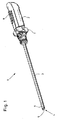
図1は、近位ハンドグリップ2と、硬質の内視鏡シャフト3とを備える本発明に係るビデオ内視鏡1の概略斜視図を示す。視野窓5は、内視鏡シャフト3の遠位端4に配置され、視野窓5の後方に、図示されていないプリズムユニットと、図示されていない画像センサユニットとを備える内視鏡シャフトの遠位部6が配置されている。
In the drawings, identical or similar types of elements and / or parts have been given the same reference numerals so that corresponding reintroduction can be omitted.
FIG. 1 shows a schematic perspective view of a video endoscope 1 according to the present invention comprising a proximal handgrip 2 and a
遠位端4における視野窓5は、湾曲し、非対称である。よって、視野窓5は、可変である側方向視野角を担うように形成されている。視野方向の変化、すなわち内視鏡シャフト3の長手方向軸線を中心とする方位角の変化は、内視鏡シャフト3の中心回転軸すなわち長手方向軸線を中心とする、ハンドグリップ2の回転によってもたらされる。内視鏡シャフト3の被覆管は、ハンドグリップに接続される。遠位端4における図示されていないプリズムユニットもまた、ハンドグリップ2の回転に伴って回転する。
The
ハンドグリップ2は、第1制御要素として形成された回転ホイール7と、スライドスイッチ8として形成された第2制御要素とを備える。
回転ホイール7は、表示画像の水平位を維持するためのハンドグリップ2の回転中は、固定保持されている。回転ホイール7が固定保持されることには、内視鏡シャフト3の内部の画像センサが動かないという効果がある。
The hand grip 2 includes a
The
視野角、すなわち直進視野からの視野方向の偏位を変更するために、スライドスイッチ8が動かされる。スライドスイッチ8を遠位方向にスライドさせると、例えば、視野角の増大がもたらされ、この場合に、スライドスイッチ8を近位方向に戻すと、直進視野に至るまでの視野角の減少がもたらされる。プリズムユニットの回転があっても表示画像の水平位を維持するために、スライドスイッチ8の作動は画像センサの回転を伴う。
The
図2は、適切なプリズムユニット10の概略側面図を示す。左側では、鎖線として示されている中央光路21の光が視野窓5を通って入射し、入射レンズ11を通って第1遠位プリズム12の中に入射する。この光は、鏡面13に当たって、第2プリズム14および第2プリズムの鏡面15に向かう方向へと、下方に反射される。鏡面15は、第2プリズム14の下側17に対して鋭角を有しているため、中央光路が、同じく鏡面仕上げされた下側17の中央部に最初に反射されて、下側17の中央部から第2プリズム14の第2鏡面16へと反射される。この第2鏡面16も下側17に対して鋭角を有しているため、中央光路が再び上方に反射される(軸線B)。そこで、この光は、鏡面19を有する第3プリズム18の中に入射し、プリズム18を通って中央光路21の光は、内視鏡シャフト3の長手方向軸線に平行な方向に集中的に再び反射され、そこで出射レンズ20を通ってプリズムユニット10から出射する。プリズムユニット10の上側に、光ファイバー束25の一部も同じく示されている。光ファイバー束25を用いて近位端から遠位端へと光が導かれ、照らさなければ暗い術野を照らすようになる。
FIG. 2 shows a schematic side view of a
第1プリズム12は、側方視野角を調整するために、垂直な軸線Aを中心に回転可能である。これにより、近位側にさらに導かれる画像の水平位が、第1プリズム12の軸線Aを中心とする回転の間に変化するように、鏡面13および15も互いに逆行回転する。これは、1つまたは複数の画像センサの回転によって、補償されなければならない。
The
図3は、図2のプリズムユニット10の概略上面図を示す。左側は、第1プリズム12が0°の視野方向においてどのように配置されているかを示している(実線)。点線で同じく示されているのは、第1プリズム12が入射レンズ11とともに回転軸線Aを中心に回転したところである。この場合、第1プリズム12の鏡面13と第2プリズム14の鏡面15との重複領域が回転する。水平位もまた、それに応じて回転する。
FIG. 3 shows a schematic top view of the
たとえて言うならば、この水平回転は、以下のように説明することができる。図2における回転軸線Aが上向きに、すなわち、想像上の水平な線である水平線に対して垂直に配置されるように、プリズムユニット10が配置されていれば、この水平な線は、プリズム12の鏡面13上の高さの線として表される。回転軸を中心とする第1プリズム12の回転があっても、これは回転角と無関係である。水平な線であるこの想像上の水平線は、鏡面13上でも水平な線のままである。この想像上の水平な線は、図3において実線で示されているように視野方向として0°が設定されていれば、ある高さにある、つまり、内視鏡1の長手方向軸線に垂直に配置された、第2プリズム14の第1鏡面15上の線の上に再び描かれる。図3において点線で示されるように、第1プリズム12が回転軸線Aを中心に回転すると、この水平な線も鏡面13上で回転し、ひいては第2プリズム14の鏡面15に対して回転する。この水平な線は、ここで、鏡面15を横切って延在し、ひいては回転する。これは、補償されなければならない。
For example, this horizontal rotation can be explained as follows. If the
図4は、本発明に係るビデオ内視鏡の、本発明に係る駆動装置30の第1例示実施形態を、概略断面で示している。これは、ハンドグリップ2と内視鏡シャフト3との間の遷移領域に関する。ハンドグリップ2は、近位側回転ホイール7を備える。ハンドグリップ2およびハンドグリップ2の一部である回転ホイール7の内部は、気密チャンバ36内に位置し、気密チャンバ36は、近位側で内視鏡シャフト3の被覆管9に組み込まれて、ハンドグリップ2の中にも延在している。回転体32および並進体34は、気密チャンバ36内で中心に配置されている。回転体32は、図示されていないその遠位端で、1つまたは複数の画像センサを備えるユニットを支持する一方、並進体34は、図示されていないその先端で、図2および3の第1プリズムの回転を引き起こす。
FIG. 4 shows, in a schematic cross section, a first exemplary embodiment of a
回転ホイール7は、ハンドグリップ2に対して回転可能に配置される。回転ホイール7は、磁気カップリング38を備え、磁気カップリング38は、ハンドグリップ2に対する回転ホイール7の回転が磁気カップリング38の内部磁石リングに伝達されるように形成されている。この内部磁石リングは、回転可能に固定された態様で、磁石支持体42に接続される。磁石支持体42に取り付けられた電気モータ46は、歯車50を介して、斜めの円周溝を有する溝体58と連絡する歯車54を動かす。中央回転体32は、磁石支持体42に回転可能に取り付けられ、歯車54および溝体58も同様である。
The
ピン60は、並進体34が溝体58の溝に延在して、ひいては溝体58の回転が並進体34の並進運動をもたらすことを確実にする。同時に、磁石支持体42は、回転ホイール7に固定可能であり、それにより、基準は水平位に設定される。
The
視野方向は、ハンドグリップ2の回転によって変化する。これは、遠位プリズムユニットの位置に影響を与えるが、画像センサの位置には影響を与えない。ハンドグリップ2には、外部磁石リングと内部磁石とを備える第2磁気カップリング40もあり、第2磁気カップリング40によってさらに、回転が第2磁石支持体44に伝達され得る。第2電気モータ48は、回転可能に固定された態様で磁石支持体44に配置され、モータが、歯車52および56を介して、磁石支持体44における回転体32およびさらなる部品の回転を、続いて可能にする。このようにして、水平位の基準が可能になる。
The visual field direction is changed by the rotation of the hand grip 2. This affects the position of the distal prism unit, but does not affect the position of the image sensor. The handgrip 2 also has a second
図4には示されていない第2制御要素は、しかしながら、視野角を設定するための電気スイッチとして実施することが可能であり、この電気スイッチは、電気または電子同期装置を介して、2つの電気モータ46および48の作動を引き起こす。
The second control element not shown in FIG. 4 can, however, be implemented as an electrical switch for setting the viewing angle, which is switched between two via an electrical or electronic synchronizer. Causes the operation of the
図4の駆動装置30の機能は、視野角を変えるためのモータ46が気密チャンバ36内で並進体34を移動させることであり、その際、モータの運動は歯車50および54によって変換される。モータ48は、回転体32を回転させることによって、内視鏡シャフト3のアキシャル軸上の1つまたは複数の画像センサをたどるのに役立つ。2つの電気モータは、磁石支持体42および44上にそれぞれ位置し、磁石支持体42および44の位置は、回転ホイール7およびハンドグリップ2上にそれぞれ配置された磁気カップリング38および40、ならびにその磁界によって調整される。水平位は、回転ホイール7の回転によって変化し、その際、磁石支持体42に取り付けられていることによって制約されるモータ46は、回転ホイール7の運動に追随する。
The function of the
図5は、電気モータを備えていない別の例示的実施形態の図における概略断面を示している。駆動装置70は、回転体72と並進体74とに作用する同期駆動装置71を備える。回転体72は、軸受スリーブ73内に取り付けられている。
FIG. 5 shows a schematic cross section in a diagram of another exemplary embodiment without an electric motor. The
ハンドグリップ2上に配置されたスライド制御要素82は、歯車駆動装置84およびスライダ86を介して、磁気カップリング78の外部リング磁石79を軸方向に運動させる役割を果たす。よって、軸方向運動は、磁気カップリング78の内部リング磁石81に、ひいては、気密チャンバ76中に伝達される。
The
内部リング磁石81は、内部リング磁石81の軸方向運動が、並進運動、すなわち、対応する視野角の変化に対応する並進体74の摺動をもたらすように、一方の側で並進体74に直接接続される。他方の側で、内部リング磁石79は、歯付きラック90に遠位側で接続されており、歯付きラック90は、その遠位端領域に、溝支持体88の溝89に係合する留め具91を有する。溝支持体88は、螺旋状の線の部分を形成する円周溝89を有する円筒体であり、円筒体は回転可能に固定された態様で回転体72に接続されている。内部磁石リング81の軸方向の摺動運動は、留め具91の運動も引き起こし、それにより、軸方向に固定された回転体は、対応する回転に変位する。スライド制御要素82の移動は、したがって、並進体74の摺動に起因する視野角の同時変化と、回転体72の回転に起因する1つまたは複数の画像センサの対応する回転とをもたらす。
The
スライド制御要素82が移動されなければ、第1制御要素としての回転ホイール7に対するハンドグリップ2の回転は、遠位プリズム群の回転をさらにもたらす一方、対照的に、並進体74および回転体72は、静止して無回転のままである。
If the
図6は、駆動装置70を備える、本発明に係るビデオ内視鏡1の概略断面を示している。駆動装置70は、図5の駆動装置に実質的に対応する。
さらに、図6は、湾曲した視野窓5を備える内視鏡シャフト3の遠位領域を示し、視野窓5の後方には、歯車106を具備された、プリズム群10の第1プリズム12が配置されている。プリズムユニット10の第3プリズム18も示されているが、第2プリズム14は、この断面の外部に位置する。歯車106の歯と係合している並進体74の歯付き遠位部108がある。複数のレンズを備える対物レンズ104は、近位側でプリズムユニット10に、また、それに接して少なくとも1つの画像センサ102を有するセンサユニット100に、隣接している。複数の画像センサは、画質を向上させる働き、立体ビデオ画像を生成する働き、または異なる色領域における録画を可能にする働きが可能である。
FIG. 6 shows a schematic cross section of the video endoscope 1 according to the present invention, which includes the driving
Furthermore, FIG. 6 shows the distal region of the
同期駆動装置71を備える本発明に係る駆動装置70は、ハンドグリップ2の中央領域に中心的に位置している。ハンドグリップ2は、スライド制御要素8と、遠位側の回転ホイール7とを備える。回転ホイール7は、磁気カップリング78の外部磁石79に接続され、外部磁石79を用いてビデオ内視鏡1の水平位が設定される。磁気カップリング78の内部磁石リング81は、押し連結部75を介して遠位で並進体74に接続され、これによっても、並進体74の遠位領域に対する近位領域の回転が可能になる。このようにして、プリズムユニット10は、回転しながら磁気カップリング78から分離されることが可能である。回転体72は、回転しながら内部磁石リング81の内部に取り付けられる。回転体は、その遠位端においてセンサユニット100を支持する。並進体74は、ここで、内視鏡シャフト3の長手方向中心軸に対して回転体72の外側に延在している。
The
回転体72が近位側で溝支持体88に接続される一方、内部リング磁石81は、近位側で溝支持体88の溝に係合する留め具91を有する歯付きラック90に接続されている。溝支持体88が回転体72に軸方向に固定されるように、溝支持体88には、ばね92が外部から近位側に予め装着されている。
The
気密チャンバ76は、コンタクトピンが埋め込まれた気密貫通管によって近位側で密封され、そのコンタクトピンを用いて気密チャンバ76の外部との電気的接続が可能になる。気密貫通管94は、例えば、コンタクトピン96が中に成形された鋳造ガラス体であり得る。
The
気密チャンバ76の外部には、一方の側で、歯を備える連接棒83と接続要素を介して接続されるスライド制御要素8と係合している歯車駆動装置84があり、連接棒83は、スライド制御要素8の移動によって内視鏡シャフト3の軸方向にも押される。連接棒83の歯部は、歯車駆動装置84の第1歯車と係合している。歯車駆動装置84は、この移動を、磁気カップリング78の外部磁石リング79の軸方向の並進運動に変換する。
On the outside of the
図7は、歯車駆動装置84、具体的にはその外側部分の概略斜視図を示している。歯車駆動装置84は、中央穿孔を有する歯車駆動装置本体110を備え、その中央穿孔の中に気密チャンバ76の被覆管が挿入される。第1歯車112は、中心的に、すなわち中央に配置されて、図6に示されるスライド制御要素8の、矢印116の方向への移動に伴い、対応する方向に回転する。歯車駆動装置84のさらなる歯車には、適切な回転方向の矢印が付与されている。歯車駆動装置の最後の歯車114は、歯車駆動装置本体110の溝120に軸方向に移動可能に取り付けられた、プッシュアーム122の歯と係合している。ここで、プッシュアーム122は、矢印118の方向に押される。磁気カップリング78の外部リング磁石79を保持して押す保持具124を支持する2つの対称なプッシュアーム122が備えられている。
FIG. 7 shows a schematic perspective view of the
図8は、別の制御要素の変形箇所の一部を概略的に示している。ここで、この変形箇所は、軸128に配置されたレバー132、すなわちロッカーアームである。レバー132を傾けることによって、軸128も回転する。軸128は、2つの軸枠126に取り付けられている。第1歯車130は、歯車駆動装置本体110の溝120におけるプッシュアーム122の摺動を生じさせるために、軸128上に備えられて、図7にあるようなさらなる歯車と係合している。このようにして、対応するビデオ内視鏡の視野角が設定される。
FIG. 8 schematically shows part of the deformation of another control element. Here, the deformed portion is a
図9は、概略斜視的に断面で、駆動装置70の外側部分を示している。歯車駆動装置本体110と、第1歯車112と、保持具124とを備える歯車駆動装置84が近位側に示されている。保持具124には、調整リング142が固定ねじ143を用いて固定されている固定装置140が備えられ、また、この調整リングは、遠位側磁極片80と近位側磁極片80’とを備える磁気カップリング78の外部磁石リング79によって、遠位側で接合されている。外部磁石リング79は、軸方向に摺動可能に取り付けられており、磁気カップリングを軸方向に運動させるための滑り空間144が形成されている。滑り空間144は、遠位側で滑り空間コネクタ146で終端し、さらに滑り空間コネクタ146は、方位回転すなわち視野方向を制限するための止め具としてストッパ148を有する。
FIG. 9 is a schematic perspective cross-sectional view showing an outer portion of the driving
図10は、気密チャンバ76内に位置する駆動装置70の一部である内側部分を、概略的に、また斜視的表示で示している。中央には、回転体と動作可能に係合している溝152を有する溝体88があり、回転体の一部155が示されている。その一部155を有する回転体を溝体88の内側に固定するために、穿孔170が備えられている。近位側では溝体88が軸受スリーブ150に取り付けられ、溝体88および回転体が軸方向に固定されるように、圧縮ばね92によってばね圧が近位側に加えられる。溝体88は、遠位側で玉軸受154に回転可能に取り付けられる。
FIG. 10 shows a schematic and perspective view of the inner part that is part of the
溝体88の外側には、溝体88の溝152に係合する留め具91を有する歯付きラック90がある。遠位領域において、歯付きラック90は、磁気カップリング78の内部リング磁石81に軸方向に移動可能に接続されている、近位側押しスリーブ156の外面形状と係合する、内面形状を有する。これにより、リング磁石81の軸方向運動は、近位側押しスリーブ156および歯付きラック90の対応する軸方向運動をもたらし、その際、歯付きラック90および近位側押しスリーブ156は、回転しながら分離される。
Outside the
遠位側では、内部リング磁石81は、内部リング磁石81の軸方向運動を図示されないプリズム群にさらに伝達する遠位側押しスリーブ160に接続されている。
具体的には、溝体88と歯付きラック90との組み合わせは、同期駆動装置71を形成する。回転体の内部には、例えば電線を中に設置することができるチャネル162がある。
On the distal side, the
Specifically, the combination of the
図11は、図10の溝体88を斜視的に示している。溝体88の円筒部には、溝体88の外周の周りに4分の1回転を描く、溝152がある。溝体の遠位領域に配置された拡大領域は、回転体に固定するための穿孔170を有する。近位側では、止めリング174が溝体に備えられており、ばね92は、溝体88および回転体を軸方向に固定するために溝体を押すことが可能である。図11は、溝152によって設定可能な角度領域に対応する、遠位端における角度領域172を示している。溝体88は、回転体および1つまたは複数の画像センサが90°回転することを可能にする。
FIG. 11 is a perspective view of the
図12は、さらなる例示的実施形態の概略を示しており、この実施形態においては、図6および7に係る例示的実施形態とは対照的に、スライドスイッチ8の移動を磁気カップリング78の保持具124に伝達するための歯車駆動装置が全くない代わりに、レバー機構がある。この目的のために、スライドスイッチ8は、レール185に導かれた連接棒183の、対応するくぼみに係合するピン184を有する。連接棒183は、その遠位端において、下部領域の釘188上に枢動可能に取り付けられている、レバー機構におけるレバー186の連結部187に係合する。釘188のいくらか上方で、スライダ189が、磁気カップリング78の保持具124に接続されたレバー186に取り付けられている。このようにして、スライドスイッチ8および連接棒183の軸方向運動は、レバー機構におけるレバーアームの比率に応じてスライダ189のより小さい軸方向運動に変換される。本実施形態は、機械的に実施がより容易であり、遊びがほとんどまたは全くない磁気カップリング78の非常に正確な制御を可能にする。
FIG. 12 shows a schematic of a further exemplary embodiment, in which, in contrast to the exemplary embodiment according to FIGS. 6 and 7, the movement of the
図面のみから取られるものを含む、言及された全ての特徴、および他の特徴との組み合わせで開示されている個々の特徴は、個別に、また組み合わせて本発明に必要不可欠なものと見なされる。本発明に係る実施形態は、個々の特徴または複数の特徴の組み合わせによって、実施され得る。
[参照符号一覧]
1 ビデオ内視鏡
2 ハンドグリップ
3 内視鏡シャフト
4 遠位端
5 視野窓
6 遠位部
7 回転ホイール
8 スライドスイッチ
9 被覆管
10 プリズムユニット
11 入射レンズ
12 第1プリズム
13 鏡面
14 第2プリズム
15,16 鏡面
17 下側
18 第3プリズム
19 鏡面
20 出射レンズ
21 中央光路
25 光ファイバー束
30 駆動装置
32 回転体
34 並進体
36 気密チャンバ
38,40 磁気カップリング
42,44 磁石支持体
46,48 電気モータ
50,52 歯車
54,56 歯車
58 溝体
60 ピン
70 駆動装置
71 同期駆動装置
72 回転体
73 軸受スリーブ
74 並進体
75 押し連結部
76 気密チャンバ
78 磁気カップリング
79 外部リング磁石
80,80’ 磁極片
81 内部リング磁石
82 スライド制御要素
83 歯を備えた連接棒
84 歯車駆動装置
86 スライダ
88 溝支持体
89 溝
90 留め具を備えた歯付きラック
91 留め具
92 ばね
94 気密貫通管
96 コンタクトピン
100 センサユニット
102 画像センサ
104 複数のレンズを備えた対物レンズ
106 歯車
108 並進体の歯付き部
110 歯車駆動装置本体
112 第1歯車
114 最後の歯車
116,118 押し方向
120 溝
122 プッシュアーム
124 保持具
126 軸受
128 軸
130 第1歯車
132 レバー
140 固定装置
142 調整リング
143 固定ねじ
144 滑り空間
146 滑り空間コネクタ
148 ストッパ
150 軸受スリーブ
152 溝
154 玉軸受
155 回転体の一部
156 近位側押しスリーブ
158 並進カップリング
160 遠位側押しスリーブ
162 チャネル
170 穿孔
172 角度領域
174 止めリング
183 連接棒
184 ピン
185 レール
186 レバー
187 連結部
188 釘
189 スライダ
All features mentioned, including those taken only from the drawings, and individual features disclosed in combination with other features, are considered essential to the present invention individually and in combination. Embodiments according to the present invention can be implemented by individual features or combinations of features.
[List of reference codes]
DESCRIPTION OF SYMBOLS 1 Video endoscope 2
15, 16
76
Claims (14)
近位ハンドグリップ(2)と、
回転可能に固定された態様で前記ハンドグリップ(2)に接続された被覆管(9)を有する内視鏡シャフト(3)と
を備え、
前記内視鏡シャフト(3)では、少なくとも2つのプリズム(12,14,18)を有するプリズムユニット(10)が、回転可能に固定された態様で遠位側で前記被覆管(9)に接続され、
少なくとも1つの画像センサ(102)が、前記プリズムユニット(10)の後方近位側に配置され、
前記プリズムユニット(10)のうちの少なくとも1つの遠位側に配置されたプリズム(12)が、視野角を修正するために、前記内視鏡シャフト(3)の長手方向軸線と交差する回転軸(A)を中心に回転可能であり、
前記プリズムユニット(10)および前記少なくとも1つの画像センサ(102)が、前記内視鏡シャフト(3)から出て前記ハンドグリップ(2)の中まで延在する前記被覆管(9)内の気密チャンバ(36,76)内に配置された、ビデオ内視鏡(1)であって、
取得画像の水平位を設定するための第1制御要素(7)、および、前記回転可能なプリズム(12)の前記視野角を設定するための第2制御要素(8)が、前記気密チャンバ(36,76)の外部に配置され、
前記気密チャンバ(36,76)には、前記内視鏡シャフト(3)の中心回転軸に配置されて、軸方向に固定され、その遠位端に前記少なくとも1つの画像センサ(102)が固定された前記内視鏡シャフト(3)の前記長手方向軸線を中心に回転可能な少なくとも1つの回転体(32,72)と、少なくとも1つの軸方向運動可能な並進体(34,74)とを備える内部位置決めシステムが配置され、
前記並進体(34,74)が、前記内視鏡シャフト(3)の遠位端部(6)において、前記並進体(34,74)の並進運動を前記少なくとも1つの回転可能なプリズム(12)の回転に変換する歯車機構(106,108)に接続され、
前記第1制御要素(7)と前記第2制御要素(8)と備える駆動装置(30,70)が、前記回転体(32,72)および前記並進体(34,74)を運動させるように構成および設計され、
前記第1制御要素(7)を作動させると前記回転体(32,72)のみが回転し、前記第2制御要素(8)を作動させると前記並進体(34,74)が運動して、前記少なくとも1つの画像センサ(102)上に形成された画像の水平位が一定のままであるように前記回転体(32,72)が回転するように、前記駆動装置(30,70)が設計されている
ことを特徴とするビデオ内視鏡(1)。 Adjustable viewing direction,
A proximal handgrip (2);
An endoscope shaft (3) having a cladding tube (9) connected to the hand grip (2) in a rotatably fixed manner;
In the endoscope shaft (3), a prism unit (10) having at least two prisms (12, 14, 18) is connected to the cladding tube (9) on the distal side in a fixed manner in a rotatable manner. And
At least one image sensor (102) is disposed on the rear proximal side of the prism unit (10);
A rotation axis intersecting a longitudinal axis of the endoscope shaft (3) by a prism (12) arranged on the distal side of at least one of the prism units (10) to correct a viewing angle It can rotate around (A),
The prism unit (10) and the at least one image sensor (102) are hermetically sealed in the cladding tube (9) extending from the endoscope shaft (3) and into the handgrip (2). A video endoscope (1) disposed in a chamber (36, 76), comprising:
A first control element (7) for setting the horizontal position of the acquired image, and a second control element (8) for setting the viewing angle of the rotatable prism (12), the airtight chamber ( 36, 76),
The airtight chamber (36, 76) is arranged on the central rotation axis of the endoscope shaft (3) and fixed in the axial direction, and the at least one image sensor (102) is fixed at the distal end thereof. At least one rotating body (32, 72) rotatable about the longitudinal axis of the endoscope shaft (3) and at least one translational body (34, 74) movable in the axial direction. internal positioning system provided is disposed,
The translation body (34, 74) translates the translation movement of the translation body (34, 74) at the distal end (6) of the endoscope shaft (3) with the at least one rotatable prism (12). ) Connected to the gear mechanism (106, 108) for converting to rotation of
A driving device (30, 70) provided with the first control element (7) and the second control element (8) moves the rotating body (32, 72) and the translation body (34, 74). Composed and designed,
When the first control element (7) is operated, only the rotating body (32, 72) is rotated, and when the second control element (8) is operated, the translation body (34, 74) is moved, The drive device (30, 70) is designed such that the rotating body (32, 72) rotates so that the horizontal position of the image formed on the at least one image sensor (102) remains constant. A video endoscope (1) characterized by
前記駆動装置(30,70)は、前記気密チャンバ(36,76)の外部から前記回転体(32,72)に回転を伝達するための、少なくとも1つの磁気カップリング(40)を備える
ことを特徴とするビデオ内視鏡(1)。 A video endoscope (1) according to claim 1, comprising:
The drive device (30, 70) includes at least one magnetic coupling (40) for transmitting rotation from the outside of the hermetic chamber (36, 76) to the rotating body (32, 72). Feature video endoscope (1).
前記駆動装置(30,70)は、軸方向運動、および、前記並進体(34,74)の前記長手方向軸線を中心とする回転のうちの少なくとも一方を、前記気密チャンバ(36,76)の外部から前記並進体(34,74)に伝達するための、少なくとも1つの磁気カップリング(38,78)を備える
ことを特徴とするビデオ内視鏡(1)。 A video endoscope (1) according to claim 1 or 2, comprising:
The drive device (30, 70) is configured to perform at least one of axial movement and rotation of the translation body (34, 74) about the longitudinal axis of the hermetic chamber (36, 76). A video endoscope (1), comprising at least one magnetic coupling (38, 78) for transmitting to the translation body (34, 74) from outside.
電動モータ(48)が、前記回転体(32)に作用する前記磁気カップリング(40)の内部磁石支持体(44)上に配置され、動作状態で前記回転体(32)の回転を引き起こす
ことを特徴とするビデオ内視鏡(1)。 Video endoscope (1) according to claim 2 or 3,
An electric motor (48) is disposed on the inner magnet support (44) of the magnetic coupling (40) acting on the rotating body (32) and causes the rotating body (32) to rotate in an operating state. A video endoscope (1) characterized by:
電動モータ(46)が、前記並進体(34)に作用する前記磁気カップリング(38)の内部磁石支持体(42)上に配置され、動作状態で前記並進体(34)の軸方向運動を引き起こす
ことを特徴とするビデオ内視鏡(1)。 A video endoscope (1) according to one of claims 2 to 4, comprising:
An electric motor (46) is disposed on the inner magnet support (42) of the magnetic coupling (38) acting on the translation body (34) and provides axial movement of the translation body (34) in the operating state. Video endoscope characterized by causing (1).
前記2つの電動モータ(46,48)は、電子制御装置を介して制御可能、または、制御される
ことを特徴とするビデオ内視鏡(1)。 Video endoscope (1) according to claim 4 or 5,
The video endoscope (1), wherein the two electric motors (46, 48) are controllable or controlled via an electronic control unit.
前記並進体(74)に接続されるか、または前記並進体(74)と一体である第1歯車駆動部(90)を備え、かつ、前記回転体(72)と回転可能に固定された態様で接続されるか、または前記回転体(72)と一体である第2歯車駆動部を備える同期駆動装置(71)が構成され、
前記第2歯車駆動部は、前記第1歯車駆動部(90)の突出部(91)またはねじが係合する、螺旋状の線またはねじの一部を形成する円周溝(152)を有する円筒体(88)を備える
ことを特徴とするビデオ内視鏡(1)。 A video endoscope (1) according to one of claims 1 to 6 , comprising:
The aspect which is connected to the said translation body (74), or provided with the 1st gear drive part (90) integral with the said translation body (74), and was fixed to the said rotation body (72) rotatably. Or a synchronous drive device (71) comprising a second gear drive unit integrated with the rotating body (72).
The second gear drive has a circumferential groove (152) that forms part of a helical line or screw with which the protrusion (91) or screw of the first gear drive (90) engages. video endoscope, characterized in that it comprises to that cylindrical body (88) (1).
前記第2制御要素(8)は、スライドスイッチまたはレバーとして形成され、該スライドスイッチまたはレバーは、変換手段を介して、前記内視鏡シャフト(3)の前記軸方向に並進運動可能であって、前記軸方向運動可能な磁気カップリング(78)の外部磁石(79)が取り付けられている、保持具(124)に接続される
ことを特徴とするビデオ内視鏡(1)。 A video endoscope (1) according to one of claims 3 to 7, comprising:
The second control element (8) is formed as a slide switch or a lever, the slide switch or lever, via the conversion means, a translatable in the axial direction of the endoscope shaft (3) The video endoscope (1) is connected to a holder (124) to which an external magnet (79) of the axially movable magnetic coupling (78) is attached.
前記変換手段は、歯車機構(84)またはレバー機構(186〜189)であるThe conversion means is a gear mechanism (84) or a lever mechanism (186 to 189).
ことを特徴とするビデオ内視鏡(1)。A video endoscope (1) characterized by that.
前記第1制御要素(7)は、回転ホイールとして形成される
ことを特徴とするビデオ内視鏡(1)。 A video endoscope (1) according to one of claims 1 to 9 , comprising:
The first control element (7) is a video endoscope, characterized in that it is formed as a rotary wheel (1).
前記回転ホイールは、曲線付き外縁を有するThe rotating wheel has a curved outer edge
ことを特徴とするビデオ内視鏡(1)。A video endoscope (1) characterized by that.
前記回転ホイールは、少なくとも部分的に周方向に前記ハンドグリップ(2)よりも大きい半径を有するThe rotating wheel has a radius that is at least partially circumferentially greater than the hand grip (2).
ことを特徴とするビデオ内視鏡(1)。A video endoscope (1) characterized by that.
前記並進体(34,74)は並進管として形成される
ことを特徴とするビデオ内視鏡(1)。 A video endoscope (1) according to one of claims 1 to 12 , comprising:
The video endoscope (1), wherein the translation body (34, 74) is formed as a translation tube.
前記回転体(32,72)は回転管として形成されるThe rotating body (32, 72) is formed as a rotating tube.
ことを特徴とするビデオ内視鏡(1)。A video endoscope (1) characterized by that.
Applications Claiming Priority (3)
| Application Number | Priority Date | Filing Date | Title |
|---|---|---|---|
| DE102012202552.9 | 2012-02-20 | ||
| DE102012202552A DE102012202552B3 (en) | 2012-02-20 | 2012-02-20 | Video endoscope with adjustable viewing direction |
| PCT/EP2013/000413 WO2013124044A1 (en) | 2012-02-20 | 2013-02-13 | Video endoscope having an adjustable viewing direction |
Publications (3)
| Publication Number | Publication Date |
|---|---|
| JP2015512667A JP2015512667A (en) | 2015-04-30 |
| JP2015512667A5 JP2015512667A5 (en) | 2015-11-05 |
| JP5993961B2 true JP5993961B2 (en) | 2016-09-21 |
Family
ID=47720467
Family Applications (1)
| Application Number | Title | Priority Date | Filing Date |
|---|---|---|---|
| JP2014558032A Expired - Fee Related JP5993961B2 (en) | 2012-02-20 | 2013-02-13 | Video endoscope with adjustable viewing direction |
Country Status (5)
| Country | Link |
|---|---|
| US (1) | US20140357952A1 (en) |
| JP (1) | JP5993961B2 (en) |
| CN (1) | CN104080389B (en) |
| DE (1) | DE102012202552B3 (en) |
| WO (1) | WO2013124044A1 (en) |
Families Citing this family (36)
| Publication number | Priority date | Publication date | Assignee | Title |
|---|---|---|---|---|
| DE102013217449A1 (en) | 2013-09-02 | 2015-03-19 | Olympus Winter & Ibe Gmbh | Prism unit and stereo video endoscope with adjustable viewing direction |
| DE102013218229B4 (en) * | 2013-09-11 | 2015-08-20 | Olympus Winter & Ibe Gmbh | Endoscope with adjustable viewing direction |
| DE102013220945A1 (en) * | 2013-10-16 | 2015-04-30 | Olympus Winter & Ibe Gmbh | Endoscope with adjustable viewing direction |
| DE102013222279A1 (en) | 2013-11-01 | 2015-05-07 | Olympus Winter & Ibe Gmbh | Joint arrangement for an endoscope and endoscope |
| DE102014202612B4 (en) * | 2014-02-13 | 2017-08-17 | Olympus Winter & Ibe Gmbh | Prism holder assembly and endoscope with variable viewing direction |
| USD745670S1 (en) * | 2014-05-16 | 2015-12-15 | Karl Storz Gmbh & Co. Kg | Video endoscope |
| DE102014211367A1 (en) * | 2014-06-13 | 2015-12-17 | OLYMPUS Winter & lbe GmbH | Prism device and endoscope |
| CN105212889B (en) * | 2014-07-03 | 2017-05-03 | 孔垂泽 | single-hole inspection laparoscope |
| CN106572791B (en) * | 2014-12-19 | 2018-11-13 | 奥林巴斯株式会社 | Endoscopic system |
| USD798445S1 (en) * | 2015-06-17 | 2017-09-26 | Karl Storz Gmbh & Co. Kg | Electronic medical instrument |
| USD795424S1 (en) * | 2015-09-01 | 2017-08-22 | Deka Products Limited Partnership | Endoscope |
| DE202015104679U1 (en) | 2015-09-03 | 2015-09-23 | Imk Automotive Gmbh | Kinematics for an intracorporeally driven instrument of an endoscope |
| DE102015114742B4 (en) | 2015-09-03 | 2017-06-14 | Imk Automotive Gmbh | Kinematics for an intracorporeally driven instrument of an endoscope |
| JP6253857B1 (en) * | 2016-02-12 | 2017-12-27 | オリンパス株式会社 | Stereoscopic endoscope and stereoscopic endoscope system |
| USD841160S1 (en) * | 2016-04-01 | 2019-02-19 | Deka Products Limited Partnership | Endoscope |
| CN106214109B (en) * | 2016-07-29 | 2017-11-14 | 上海交通大学 | It is easy to operate can storage type anal intestine mirror |
| DE102016119861A1 (en) | 2016-10-18 | 2018-04-19 | Olympus Winter & Ibe Gmbh | Video endoscope and method for producing a plain bearing for a video endoscope |
| DE102017100056A1 (en) | 2017-01-03 | 2018-07-05 | Olympus Winter & Ibe Gmbh | Video endoscope with swiveling viewing direction and handle for a medical shaft instrument |
| EP3582676B1 (en) * | 2017-02-15 | 2023-08-16 | Lazurite Holdings LLC | Wireless medical imaging system comprising a head unit and a light cable that comprises an integrated light source |
| KR101993373B1 (en) * | 2017-07-18 | 2019-06-26 | 원텍 주식회사 | Handle structure of surgical endoscope |
| DE102017124981B4 (en) * | 2017-10-25 | 2024-03-07 | Schölly Fiberoptic GmbH | Magnetic clutch |
| US20190246884A1 (en) * | 2018-02-14 | 2019-08-15 | Suzhou Acuvu Medical Technology Co. Ltd | Endoscopy system with off-center direction of view |
| US11547466B2 (en) * | 2018-06-20 | 2023-01-10 | Covidien Lp | Visualization devices and methods for use in surgical procedures |
| DE102018128306A1 (en) * | 2018-11-13 | 2020-05-14 | Olympus Winter & Ibe Gmbh | Video endoscope and braking element |
| DE102019100147B4 (en) * | 2019-01-04 | 2022-07-28 | Olympus Winter & Ibe Gmbh | video endoscope |
| CN110151107B (en) * | 2019-04-26 | 2021-09-10 | 群曜医电股份有限公司 | Wired gastrointestinal capsule endoscope and magnetic control device |
| DE102019004433A1 (en) | 2019-06-22 | 2020-12-24 | Karl Storz Se & Co. Kg | Video endoscope and handle for a video endoscope |
| DE102019123053A1 (en) | 2019-08-28 | 2021-03-04 | Olympus Winter & Ibe Gmbh | Endoscope with optical filter arrangement and use |
| US20220395163A1 (en) * | 2019-11-15 | 2022-12-15 | Covidien Lp | Rotation assembly for endoscope lens |
| CN112006761B (en) * | 2020-09-09 | 2022-05-06 | 郑州铁路职业技术学院 | Uterine cavity visual system for obstetrics and gynecology department |
| US20220160220A1 (en) * | 2020-11-23 | 2022-05-26 | Medos International Sárl | Arthroscopic medical implements and assemblies |
| CN114305292A (en) * | 2021-11-25 | 2022-04-12 | 北京凡星光电医疗设备股份有限公司 | Rotatable electronic hard tube endoscope |
| CN114271765B (en) * | 2021-12-23 | 2022-07-12 | 青岛钰仁医疗科技有限公司 | Multifunctional composite light penetration enhanced imaging system and enhanced imaging method |
| CN116058774B (en) * | 2023-01-03 | 2023-10-03 | 中山千寻光学有限公司 | Endoscope device and imaging control method |
| CN115845178B (en) * | 2023-01-09 | 2023-08-22 | 中国人民解放军总医院第二医学中心 | Visual intestinal canal temperature measurement flushing device and use method |
| CN116350157A (en) * | 2023-04-23 | 2023-06-30 | 上海宇度医学科技股份有限公司 | Endoscope |
Family Cites Families (11)
| Publication number | Priority date | Publication date | Assignee | Title |
|---|---|---|---|---|
| US3880148A (en) * | 1972-09-25 | 1975-04-29 | Olympus Optical Co | Endoscope |
| CA2321488C (en) * | 1998-02-19 | 2008-02-12 | California Institute Of Technology | Apparatus and method for providing spherical viewing during endoscopic procedures |
| GB2354836B (en) * | 1999-09-28 | 2003-06-04 | Keymed | Improvements relating to borescopes and endoscopes with variable direction of view |
| US7175593B2 (en) * | 2000-08-30 | 2007-02-13 | Durell & Gitelis, Inc. | Variable view arthroscope with charge coupled device |
| EP1787570B1 (en) * | 2005-11-16 | 2010-12-29 | Richard Wolf GmbH | Optical instrument |
| JP2008033167A (en) * | 2006-07-31 | 2008-02-14 | Olympus Medical Systems Corp | Imaging unit |
| US9572478B2 (en) * | 2008-07-25 | 2017-02-21 | Karl Storz Imaging, Inc. | Swing prism endoscope |
| US20100030031A1 (en) * | 2008-07-30 | 2010-02-04 | Acclarent, Inc. | Swing prism endoscope |
| EP2369395B1 (en) | 2009-07-30 | 2013-10-02 | Olympus Medical Systems Corp. | Optical system for endoscope, and endoscope |
| DE102009049143B3 (en) * | 2009-10-12 | 2010-12-30 | Sopro-Comeg Gmbh | Rigid, rod shaped endoscope for examining inner organ of patient, has magnet within inner space, where movement of inner hollow tubes against innermost hollow tube takes place by forces produced by magnet |
| DE102010033425A1 (en) * | 2010-08-04 | 2012-02-09 | Karl Storz Gmbh & Co. Kg | Endoscope with adjustable viewing direction |
-
2012
- 2012-02-20 DE DE102012202552A patent/DE102012202552B3/en not_active Expired - Fee Related
-
2013
- 2013-02-13 WO PCT/EP2013/000413 patent/WO2013124044A1/en active Application Filing
- 2013-02-13 CN CN201380006686.9A patent/CN104080389B/en not_active Expired - Fee Related
- 2013-02-13 JP JP2014558032A patent/JP5993961B2/en not_active Expired - Fee Related
-
2014
- 2014-08-19 US US14/462,705 patent/US20140357952A1/en not_active Abandoned
Also Published As
| Publication number | Publication date |
|---|---|
| CN104080389A (en) | 2014-10-01 |
| CN104080389B (en) | 2016-03-23 |
| DE102012202552B3 (en) | 2013-07-11 |
| WO2013124044A1 (en) | 2013-08-29 |
| JP2015512667A (en) | 2015-04-30 |
| US20140357952A1 (en) | 2014-12-04 |
Similar Documents
| Publication | Publication Date | Title |
|---|---|---|
| JP5993961B2 (en) | Video endoscope with adjustable viewing direction | |
| US7896803B2 (en) | Variable direction of view instrument with on-board actuators | |
| JP5655078B2 (en) | Endoscope | |
| JP2007075604A (en) | Visual direction adjustable type endoscope | |
| EP2836106B1 (en) | 360 degree panning stereo endoscope | |
| JP6019026B2 (en) | Stereoscopic endoscope | |
| JP5997170B2 (en) | Imaging apparatus and rigid endoscope | |
| US20150112141A1 (en) | Rotational Device And Method For Rotating An Endoscope | |
| JP5399587B2 (en) | Medical equipment | |
| CN102736239A (en) | Endoscope with variable view angle | |
| WO2007074571A1 (en) | Endoscope and endoscope system | |
| WO2012132372A1 (en) | Endoscope device | |
| WO2019244442A1 (en) | Exchange lens, imaging device, and rotation detection device | |
| JP5799213B2 (en) | Endoscope | |
| JP2005287576A (en) | Control cable of endoscope | |
| JP2012075777A (en) | Endoscope | |
| JP2011081319A (en) | Imaging apparatus | |
| TWM565552U (en) | 3D medical microscope | |
| JP2010214053A (en) | Actuator built-in distal end of endoscope | |
| JP5159541B2 (en) | End stop motor motor stop device | |
| JPH11326783A (en) | Hard zoom endoscope | |
| CN114010135A (en) | Moving frame, zoom endoscope, endoscope zooming method and endoscope system | |
| JP2002301015A (en) | Electronic endoscope for magnifying observation | |
| JP2012152435A (en) | Endoscope | |
| JP2005143689A (en) | Zoom endoscope |
Legal Events
| Date | Code | Title | Description |
|---|---|---|---|
| A521 | Written amendment |
Free format text: JAPANESE INTERMEDIATE CODE: A523 Effective date: 20150911 |
|
| A621 | Written request for application examination |
Free format text: JAPANESE INTERMEDIATE CODE: A621 Effective date: 20150911 |
|
| A977 | Report on retrieval |
Free format text: JAPANESE INTERMEDIATE CODE: A971007 Effective date: 20160728 |
|
| TRDD | Decision of grant or rejection written | ||
| A01 | Written decision to grant a patent or to grant a registration (utility model) |
Free format text: JAPANESE INTERMEDIATE CODE: A01 Effective date: 20160802 |
|
| A61 | First payment of annual fees (during grant procedure) |
Free format text: JAPANESE INTERMEDIATE CODE: A61 Effective date: 20160822 |
|
| R150 | Certificate of patent or registration of utility model |
Ref document number: 5993961 Country of ref document: JP Free format text: JAPANESE INTERMEDIATE CODE: R150 |
|
| LAPS | Cancellation because of no payment of annual fees |