JP5992430B2 - System and method for non-optimized handoff - Google Patents
System and method for non-optimized handoff Download PDFInfo
- Publication number
- JP5992430B2 JP5992430B2 JP2013539988A JP2013539988A JP5992430B2 JP 5992430 B2 JP5992430 B2 JP 5992430B2 JP 2013539988 A JP2013539988 A JP 2013539988A JP 2013539988 A JP2013539988 A JP 2013539988A JP 5992430 B2 JP5992430 B2 JP 5992430B2
- Authority
- JP
- Japan
- Prior art keywords
- network
- context
- configuration option
- packet data
- request
- Prior art date
- Legal status (The legal status is an assumption and is not a legal conclusion. Google has not performed a legal analysis and makes no representation as to the accuracy of the status listed.)
- Active
Links
- 238000000034 method Methods 0.000 title claims description 68
- 238000004891 communication Methods 0.000 claims description 95
- 230000011664 signaling Effects 0.000 claims description 39
- 230000000977 initiatory effect Effects 0.000 claims description 2
- 238000005516 engineering process Methods 0.000 description 34
- 238000010586 diagram Methods 0.000 description 23
- 238000012545 processing Methods 0.000 description 17
- 238000004590 computer program Methods 0.000 description 15
- 238000013507 mapping Methods 0.000 description 15
- 230000008569 process Effects 0.000 description 14
- 230000007774 longterm Effects 0.000 description 11
- 230000006870 function Effects 0.000 description 10
- 230000004044 response Effects 0.000 description 10
- 238000012790 confirmation Methods 0.000 description 9
- 230000002441 reversible effect Effects 0.000 description 8
- 238000012423 maintenance Methods 0.000 description 6
- 238000011084 recovery Methods 0.000 description 6
- 230000005540 biological transmission Effects 0.000 description 5
- 230000003287 optical effect Effects 0.000 description 5
- 238000012546 transfer Methods 0.000 description 5
- 230000007704 transition Effects 0.000 description 5
- 238000013475 authorization Methods 0.000 description 4
- 230000008901 benefit Effects 0.000 description 4
- 238000004422 calculation algorithm Methods 0.000 description 3
- 238000013461 design Methods 0.000 description 3
- 239000011159 matrix material Substances 0.000 description 3
- 238000010295 mobile communication Methods 0.000 description 3
- 238000013459 approach Methods 0.000 description 2
- 230000001143 conditioned effect Effects 0.000 description 2
- 238000011161 development Methods 0.000 description 2
- 230000003993 interaction Effects 0.000 description 2
- 230000004048 modification Effects 0.000 description 2
- 238000012986 modification Methods 0.000 description 2
- 230000008520 organization Effects 0.000 description 2
- 238000000926 separation method Methods 0.000 description 2
- 230000009471 action Effects 0.000 description 1
- 238000004458 analytical method Methods 0.000 description 1
- 238000003491 array Methods 0.000 description 1
- 238000004364 calculation method Methods 0.000 description 1
- 230000001413 cellular effect Effects 0.000 description 1
- 230000008859 change Effects 0.000 description 1
- 238000001914 filtration Methods 0.000 description 1
- 230000006872 improvement Effects 0.000 description 1
- 239000006249 magnetic particle Substances 0.000 description 1
- 230000006855 networking Effects 0.000 description 1
- 238000005457 optimization Methods 0.000 description 1
- 239000002245 particle Substances 0.000 description 1
- 230000003595 spectral effect Effects 0.000 description 1
- 239000013589 supplement Substances 0.000 description 1
Images


Classifications
-
- H—ELECTRICITY
- H04—ELECTRIC COMMUNICATION TECHNIQUE
- H04W—WIRELESS COMMUNICATION NETWORKS
- H04W36/00—Hand-off or reselection arrangements
- H04W36/02—Buffering or recovering information during reselection ; Modification of the traffic flow during hand-off
-
- H—ELECTRICITY
- H04—ELECTRIC COMMUNICATION TECHNIQUE
- H04W—WIRELESS COMMUNICATION NETWORKS
- H04W36/00—Hand-off or reselection arrangements
- H04W36/0005—Control or signalling for completing the hand-off
- H04W36/0011—Control or signalling for completing the hand-off for data sessions of end-to-end connection
- H04W36/0033—Control or signalling for completing the hand-off for data sessions of end-to-end connection with transfer of context information
-
- H—ELECTRICITY
- H04—ELECTRIC COMMUNICATION TECHNIQUE
- H04W—WIRELESS COMMUNICATION NETWORKS
- H04W36/00—Hand-off or reselection arrangements
- H04W36/0005—Control or signalling for completing the hand-off
- H04W36/0055—Transmission or use of information for re-establishing the radio link
- H04W36/0069—Transmission or use of information for re-establishing the radio link in case of dual connectivity, e.g. decoupled uplink/downlink
- H04W36/00692—Transmission or use of information for re-establishing the radio link in case of dual connectivity, e.g. decoupled uplink/downlink using simultaneous multiple data streams, e.g. cooperative multipoint [CoMP], carrier aggregation [CA] or multiple input multiple output [MIMO]
-
- H—ELECTRICITY
- H04—ELECTRIC COMMUNICATION TECHNIQUE
- H04W—WIRELESS COMMUNICATION NETWORKS
- H04W36/00—Hand-off or reselection arrangements
- H04W36/14—Reselecting a network or an air interface
-
- H—ELECTRICITY
- H04—ELECTRIC COMMUNICATION TECHNIQUE
- H04W—WIRELESS COMMUNICATION NETWORKS
- H04W36/00—Hand-off or reselection arrangements
- H04W36/14—Reselecting a network or an air interface
- H04W36/144—Reselecting a network or an air interface over a different radio air interface technology
- H04W36/1443—Reselecting a network or an air interface over a different radio air interface technology between licensed networks
-
- H—ELECTRICITY
- H04—ELECTRIC COMMUNICATION TECHNIQUE
- H04W—WIRELESS COMMUNICATION NETWORKS
- H04W36/00—Hand-off or reselection arrangements
- H04W36/16—Performing reselection for specific purposes
- H04W36/18—Performing reselection for specific purposes for allowing seamless reselection, e.g. soft reselection
Description
本出願は、その全体の中に参照により組み込まれる、2010年11月16日に出願された「APPARATUS AND METHOD FOR ENHANCED NON OPTIMIZED HANDOVER」と題する米国仮特許出願第61/414,365号からの優先権を主張する。本出願はまた、その全体の中に参照により組み込まれる、2011年2月7日に出願された「IMPROVED NON-OPTIMIZED HANDOFF FROM A FIRST NETWORK TO A SECOND NETWORK」と題する米国仮特許出願第61/440,382号からの優先権を主張する。 This application is a priority from US Provisional Patent Application No. 61 / 414,365 entitled “APPARATUS AND METHOD FOR ENHANCED NON OPTIMIZED HANDOVER” filed on Nov. 16, 2010, which is incorporated by reference in its entirety. Insist on the right. This application is also incorporated by reference in its entirety, US Provisional Patent Application No. 61/440 entitled “IMPROVED NON-OPTIMIZED HANDOFF FROM A FIRST NETWORK TO A SECOND NETWORK” filed on Feb. 7, 2011. , Claim priority from No.382.
本出願は、一般に通信に関し、より詳細には、ロングタームエボリューション(long-term evolution)(LTE)ネットワークから発展型高速パケットデータ(evolved high rate packet data)(eHRPD)ネットワークへのハンドオフに関する。 The present application relates generally to communications, and more particularly to handoffs from long-term evolution (LTE) networks to evolved high rate packet data (eHRPD) networks.
ワイヤレス通信システムは、音声およびデータなど、様々なタイプの通信コンテンツを提供するために広く展開されている。典型的なワイヤレス通信システムは、利用可能なシステムリソース(たとえば、帯域幅、送信電力)を共有することによって複数のユーザとの通信をサポートすることが可能な多元接続システムであり得る。そのような多元接続システムの例は、符号分割多元接続(CDMA)システム、時分割多元接続(TDMA)システム、周波数分割多元接続(FDMA)システム、直交周波数分割多元接続(OFDMA)システムなどを含み得る。さらに、これらのシステムは、第3世代パートナーシッププロジェクト(3GPP)、3GPP2、3GPPロングタームエボリューション(LTE)、LTE Advanced(LTE−A)などの規格に準拠することができる。 Wireless communication systems are widely deployed to provide various types of communication content such as voice and data. A typical wireless communication system may be a multiple access system that can support communication with multiple users by sharing available system resources (eg, bandwidth, transmit power). Examples of such multiple access systems may include code division multiple access (CDMA) systems, time division multiple access (TDMA) systems, frequency division multiple access (FDMA) systems, orthogonal frequency division multiple access (OFDMA) systems, and the like. . In addition, these systems can comply with standards such as 3rd Generation Partnership Project (3GPP), 3GPP2, 3GPP Long Term Evolution (LTE), LTE Advanced (LTE-A) and the like.
一般に、ワイヤレス多元接続通信システムは、複数のモバイルデバイスのための通信を同時にサポートし得る。各モバイルデバイスは、順方向リンクおよび逆方向リンク上の送信を介して1つまたは複数の基地局と通信し得る。順方向リンク(またはダウンリンク)は基地局からモバイルデバイスへの通信リンクを指し、逆方向リンク(またはアップリンク)はモバイルデバイスから基地局への通信リンクを指す。 In general, a wireless multiple-access communication system can simultaneously support communication for multiple mobile devices. Each mobile device may communicate with one or more base stations via transmissions on forward and reverse links. The forward link (or downlink) refers to the communication link from base stations to mobile devices, and the reverse link (or uplink) refers to the communication link from mobile devices to base stations.
高速データサービスおよびマルチメディアデータサービスに対する要求が急速に増大するにつれて、向上した性能をもつ効率的でロバストな通信システムの実装についての努力がなされている。たとえば、近年、ユーザは、固定回線通信をモバイル通信と取り替え始めており、高い音声品質、信頼できるサービス、および低価格をますます要求している。 As the demand for high-speed data services and multimedia data services increases rapidly, efforts are being made to implement efficient and robust communication systems with improved performance. For example, in recent years, users have begun to replace fixed line communications with mobile communications and increasingly demand high voice quality, reliable service, and low prices.
増加する要求に対応するために、無線インターフェースの発展の後にワイヤレス通信システムのコアネットワークの発展が続いた。たとえば、3GPPによって導かれたSystem Architecture Evolution(SAE)は、Global System for Mobile communications(GSM(登録商標))/General Packet Radio Service(GPRS)コアネットワークを発展させることを目的とする。結果として生じたEvolved Packet Core(EPC)は、オペレータが、複数の無線アクセス技術を用いて1つの共通のパケットベースコアネットワークを展開し、利用することを可能にする、インターネットプロトコル(IP)に基づく多重アクセスコアネットワークである。EPCは、モバイルデバイスのための最適化されたモビリティを提供し、異なる無線アクセス技術間(たとえば、LTEと高速パケットデータ(HRPD)との間)の効率的なハンドオーバを可能にする。さらに、規格化されたローミングインターフェースは、オペレータが様々なアクセス技術にわたって加入者にサービスを提供することを可能にする。 In response to the increasing demand, the development of the core network of the wireless communication system followed the development of the radio interface. For example, the System Architecture Evolution (SAE), led by 3GPP, aims to develop a Global System for Mobile communications (GSM®) / General Packet Radio Service (GPRS) core network. The resulting Evolved Packet Core (EPC) is based on the Internet Protocol (IP) that allows operators to deploy and use a common packet-based core network using multiple radio access technologies. It is a multiple access core network. EPC provides optimized mobility for mobile devices and enables efficient handover between different radio access technologies (eg, between LTE and high-speed packet data (HRPD)). In addition, a standardized roaming interface allows an operator to provide services to subscribers across a variety of access technologies.
添付のクレームの範囲内のシステム、方法およびデバイスの様々な実装は、それぞれいくつかの態様を有し、それらのうちの単一の態様が、単独で、ここに説明する望ましい特性(attributes)を担うとは限らない。添付のクレームの範囲を限定することなしに、いくつかの顕著な特徴がここに説明される。 Various implementations of systems, methods and devices within the scope of the appended claims each have several aspects, and a single aspect of them alone has the desired attributes described herein. Not necessarily responsible. Without limiting the scope of the appended claims, some salient features are described herein.
本明細書で説明する主題の1つまたは複数の実装の詳細は、添付の図面および以下の説明に示されている。他の特徴、態様、および利点は、明細書、図面、およびクレームから明らかになるであろう。以下の図の相対的な寸法は一定の縮尺で描かれていないことがあることに留意されたい。 The details of one or more implementations of the subject matter described in this specification are set forth in the accompanying drawings and the description below. Other features, aspects, and advantages will be apparent from the description, drawings, and claims. Note that the relative dimensions in the following figures may not be drawn to scale.
本開示で説明する主題の一態様は、ワイヤレス通信システムにおけるハンドオフの方法の実装を提供する。本方法は、データ非アクティビティ(inactivity)期間中に、第1のネットワークにアタッチし、それとのコンテキストを作成することを含み、第1のネットワークは、第2のネットワークと比較して好適でない(non-preferred)ネットワークである。本方法はまた、第1のネットワークとの少なくとも部分コンテキストを維持しながら、第1のネットワークとの作成されたコンテキストに基づいて第2のネットワークに接続することを含む。本方法は、第1のネットワークから第2のネットワークに切り替えること、たとえば、ロングタームエボリューション無線アクセス技術から発展型高速パケットデータ無線アクセス技術に切り替えることを含み得る。切り替えることは、元のコンテキストを回復することを含み得る。 One aspect of the subject matter described in the disclosure provides an implementation of a method of handoff in a wireless communication system. The method includes attaching to and creating a context with a first network during a data inactivity period, the first network being less suitable than the second network. -preferred) Network. The method also includes connecting to the second network based on the created context with the first network while maintaining at least a partial context with the first network. The method may include switching from a first network to a second network, eg, switching from a long term evolution radio access technology to an evolved high-speed packet data radio access technology. Switching may include restoring the original context.
いくつかの実装では、元のコンテキストを回復することは、シグナリングチャネルを使用して、パケットデータネットワークへの接続を確立するための要求を第1のネットワークに送信することを含む。回復はまた、第1のネットワーク上でトラフィックチャネルを確立することを含み得る。いくつかの実装では、トラフィックチャネルが確立される前に、パケットデータネットワークへの接続を確立するための要求が送信される。ソースネットワークは、ロングタームエボリューション無線アクセス技術を使用するように構成されたネットワークであり得、ソースネットワークは、発展型高速パケットデータ無線アクセス技術を使用するように構成され得る。 In some implementations, restoring the original context includes sending a request to the first network to establish a connection to the packet data network using the signaling channel. Recovery may also include establishing a traffic channel on the first network. In some implementations, a request to establish a connection to the packet data network is sent before the traffic channel is established. The source network may be a network configured to use long term evolution radio access technology, and the source network may be configured to use evolved high-speed packet data radio access technology.
本開示で説明する主題の別の態様は、通信ネットワークにおいて作用するワイヤレス通信装置を提供する。本装置はプロセッサを含む。本プロセッサは、データ非アクティビティ期間中に、第1のネットワークにアタッチし、それとのコンテキストを作成するように構成され、第1のネットワークは第2のネットワークと比較して好適でないネットワークである。本プロセッサは、第1のネットワークとの少なくとも部分コンテキストを維持しながら、第1のネットワークとの作成されたコンテキストに基づいて第2のネットワークに接続するようにさらに構成される。本プロセッサは、シグナリングチャネルを使用して、パケットデータネットワークへの接続を確立するための要求をターゲットネットワークに送信するように構成され得る。 Another aspect of the subject matter described in the disclosure provides a wireless communication apparatus that operates in a communication network. The apparatus includes a processor. The processor is configured to attach to and create a context with the first network during data inactivity, the first network being an unsuitable network compared to the second network. The processor is further configured to connect to the second network based on the created context with the first network while maintaining at least a partial context with the first network. The processor can be configured to send a request to a target network to establish a connection to a packet data network using a signaling channel.
本開示で説明する主題のさらに別の態様は、通信ネットワークにおいて作用するワイヤレス通信装置を提供する。本装置は、データ非アクティビティ期間中に、第1のネットワークにアタッチし、それとのコンテキストを作成するための手段を含み、第1のネットワークは第2のネットワークと比較して好適でないネットワークである。本装置はまた、第1のネットワークとの少なくとも部分コンテキストを維持しながら、第1のネットワークとの作成されたコンテキストに基づいて第2のネットワークに接続するための手段を含む。 Yet another aspect of the subject matter described in the disclosure provides a wireless communication apparatus that operates in a communication network. The apparatus includes means for attaching to and creating a context with the first network during data inactivity, the first network being a less preferred network compared to the second network. The apparatus also includes means for connecting to the second network based on the created context with the first network while maintaining at least a partial context with the first network.
本開示で説明する主題の別の態様は、コンピュータ可読媒体を備えるコンピュータプログラム製品を提供する。本コンピュータ可読媒体は、データ非アクティビティ期間中に、第1のネットワークにアタッチし、それとのコンテキストを作成することをコンピュータに行わせるためのコードを含み、第1のネットワークは第2のネットワークと比較して好適でないネットワークである。本コンピュータ可読媒体はまた、第1のネットワークとの少なくとも部分コンテキストを維持しながら、第1のネットワークとの作成されたコンテキストに基づいて第2のネットワークに接続するためのコードを含む。 Another aspect of the subject matter described in the disclosure provides a computer program product comprising a computer-readable medium. The computer-readable medium includes code for causing a computer to attach to and create a context with a first network during a period of data inactivity, the first network being compared to the second network Therefore, it is an unsuitable network. The computer-readable medium also includes code for connecting to the second network based on the created context with the first network while maintaining at least a partial context with the first network.
慣例により、図面に示す様々な特徴は一定の縮尺で描かれていないことがある。したがって、様々な特徴の寸法は、明瞭のために任意に拡大または縮小されることがある。さらに、図面のいくつかは、所与のシステム、方法またはデバイスのコンポーネントのすべてを示しているとは限らないことがある。最後に、明細書および図の全体にわたって同様の特徴を示すために同様の参照数字が使用されることがある。 By convention, the various features illustrated in the drawings may not be drawn to scale. Accordingly, the dimensions of the various features may be arbitrarily expanded or reduced for clarity. Moreover, some of the drawings may not illustrate all of the components of a given system, method or device. Finally, like reference numerals may be used to indicate like features throughout the specification and figures.
添付のクレームの範囲内の実装の様々な態様は、以下で説明される。ここに説明する態様は広く多種多様な形態で実装され得、ここに説明する任意の特定の構造および/または機能は、単に実例となるものにすぎないことは明らかであろう。本開示に基づいて、ここに説明する態様は任意の他の態様から独立して実装され得ること、およびこれらの態様のうちの2つ以上は様々な方法で組み合わせられ得ることを当業者なら諒解されたい。たとえば、ここに示す任意の数の態様を使用して、装置が実装され得、および/または方法が実施され得る。さらに、ここに示す態様のうちの1つまたは複数に加えて、あるいはそれら以外の他の構造および/または機能を使用して、そのような装置が実装され得、および/またはそのような方法が実施され得る。 Various aspects of implementation within the scope of the appended claims are described below. It will be apparent that the aspects described herein may be implemented in a wide variety of forms, and that any particular structure and / or function described herein is merely illustrative. Based on this disclosure, those skilled in the art will appreciate that the aspects described herein can be implemented independently of any other aspects, and that two or more of these aspects can be combined in various ways. I want to be. For example, any number of aspects shown herein may be used to implement an apparatus and / or implement a method. Moreover, such devices may be implemented and / or such methods may be implemented in addition to one or more of the aspects shown herein, or using other structures and / or functions other than these. Can be implemented.
「例示的」という単語は、ここでは「例、事例、または例示の働きをすること」を意味するために使用される。「例示的」としてここに説明するいかなる実装も、必ずしも他の実装よりも好適または有利なものと解釈されるべきではない。以下の説明は、いかなる当業者でも本発明を製作および使用することができるように示される。説明の目的で、以下の説明において詳細が示される。本発明はこれらの特定の詳細の使用なしに実施され得ることを当業者は了解するであろうことを諒解されたい。他の例では、本発明の説明を不要な詳細で不明瞭に(obscure)しないために、よく知られている構造およびプロセスは詳述されない。したがって、本発明は、示される実装に限定されることを意図されたものではなく、ここに開示する原理および特徴と一致する最も広い範囲を与えられる(accorded)べきである。 The word “exemplary” is used herein to mean “serving as an example, instance, or illustration”. Any implementation described herein as "exemplary" is not necessarily to be construed as preferred or advantageous over other implementations. The following description is presented to enable any person skilled in the art to make and use the invention. For purposes of explanation, details are set forth in the following description. It should be appreciated by those skilled in the art that the present invention may be practiced without the use of these specific details. In other instances, well-known structures and processes are not elaborated in order not to obscure the description of the present invention with unnecessary detail. Accordingly, the present invention is not intended to be limited to the implementations shown, but is to be accorded with the widest scope consistent with the principles and features disclosed herein.
ここに説明する技法は、符号分割多元接続(CDMA)ネットワーク、時分割多元接続(TDMA)ネットワーク、周波数分割多元接続(FDMA)ネットワーク、直交FDMA(OFDMA)ネットワーク、シングルキャリアFDMA(SC−FDMA)ネットワークなどのような、様々なワイヤレス通信ネットワークのために使用され得る。「ネットワーク」および「システム」という用語は、しばしば互換的に使用される。CDMAネットワークは、ユニバーサル地上波無線アクセス(Universal Terrestrial Radio Access)(UTRA)、cdma2000などのような無線技術を実装し得る。UTRAは、広帯域CDMA(W−CDMA(登録商標))および低チップレート(LCR)を含む。cdma2000は、IS−2000、IS−95およびIS−856規格をカバーする。TDMAネットワークは、Global System for Mobile Communications(GSM(登録商標))などの無線技術を実装し得る。OFDMAネットワークは、Evolved UTRA(E−UTRA)、IEEE802.11、IEEE802.16、IEEE802.20、Flash−OFDM(登録商標)などのような無線技術を実装し得る。UTRA、E−UTRA、およびGSM(登録商標)は、Universal Mobile Telecommunication System(UMTS)の一部である。ロングタームエボリューション(LTE)は、E−UTRAを使用するUMTSのリリースである。UTRA、E−UTRA、GSM(登録商標)、UMTSおよびLTEは、「3rd Generation Partnership Project」(3GPP)と称する団体からの文書に記載されている。cdma2000は、「3rd Generation Partnership Project 2」(3GPP2)と称する団体からの文書に記載されている。これらの様々な無線技術および規格は当技術分野で知られている。
The techniques described herein include code division multiple access (CDMA) networks, time division multiple access (TDMA) networks, frequency division multiple access (FDMA) networks, orthogonal FDMA (OFDMA) networks, and single carrier FDMA (SC-FDMA) networks. Can be used for various wireless communication networks, such as. The terms “network” and “system” are often used interchangeably. A CDMA network may implement a radio technology such as Universal Terrestrial Radio Access (UTRA), cdma2000, and so on. UTRA includes wideband CDMA (W-CDMA®) and low chip rate (LCR). cdma2000 covers IS-2000, IS-95 and IS-856 standards. A TDMA network may implement a radio technology such as Global System for Mobile Communications (GSM). An OFDMA network may implement radio technologies such as Evolved UTRA (E-UTRA), IEEE 802.11, IEEE 802.16, IEEE 802.20, Flash-OFDM®, and so on. UTRA, E-UTRA, and GSM® are part of the Universal Mobile Telecommunication System (UMTS). Long Term Evolution (LTE) is a release of UMTS that uses E-UTRA. UTRA, E-UTRA, GSM®, UMTS and LTE are described in documents from an organization named “3rd Generation Partnership Project” (3GPP). cdma2000 is described in documents from an organization named “3rd
シングルキャリア変調および周波数領域等化(frequency domain equalization)を利用するシングルキャリア周波数分割多元接続(SC−FDMA)は、ワイヤレス通信システムにおいて使用される1つの技法である。SC−FDMAは、OFDMAシステムと同様の性能および本質的に同じ全体的な複雑さ(overall complexity)を有する。SC−FDMA信号は、それの固有のシングルキャリア構造のために、より低いピーク対平均電力比(peak-to-average power ratio)(PAPR)を有する。SC−FDMAは、特に、より低いPAPRが送信電力効率の点でモバイル端末に多大な利益になるアップリンク通信において、大きい注目を引いている。それは現在、3GPPロングタームエボリューション(LTE)、またはEvolved UTRAにおけるアップリンク多元接続方式に関する実用的な前提(assumption)である。 Single carrier frequency division multiple access (SC-FDMA), which utilizes single carrier modulation and frequency domain equalization, is one technique used in wireless communication systems. SC-FDMA has similar performance and essentially the same overall complexity as an OFDMA system. SC-FDMA signals have a lower peak-to-average power ratio (PAPR) because of their inherent single carrier structure. SC-FDMA has drawn great attention, especially in uplink communications where lower PAPR greatly benefits the mobile terminal in terms of transmit power efficiency. It is currently a practical assumption regarding uplink multiple access schemes in 3GPP Long Term Evolution (LTE) or Evolved UTRA.
さらに、以下の説明では、簡潔性および明暸性の理由で、ロングタームエボリューション(LTE)Evolved Universal Terrestrial Radio Access(E−UTRA)システムに関連する用語が使用される。LTE E−UTRA技術は、その全体の中に参照によりここに組み込まれる、3GPP TS23.401:GPRS Enhancements for E−UTRAN Access(Release 8)にさらに記載されている。本発明はまた、広帯域符号分割多元接続(WCDMA(登録商標))、時分割多元接続(TDMA)、直交周波数分割多元接続(OFDMA)、発展型高速パケットデータ(eHRPD)などに関係する技術およびその関連規格など、他の技術に適用でき得ることが強調されるべきである。異なる技術に関連する用語は異なることがある。たとえば、考察する技術に依存して、LTEにおいて使用されるユーザ機器(UE)は、ほんのいくつかの例を挙げれば、移動局、ユーザ端末、加入者ユニット、アクセス端末などと時々呼ばれることがある。同様に、LTEにおいて使用されるサービングゲートウェイ(SGW)は、ゲートウェイ、HRPDサービングゲートウェイなどと時々呼ばれることがある。同様に、LTEにおいて使用される発展型ノードB(eNB)は、アクセスノード、アクセスポイント、基地局、ノードB、HRPD基地局(BTS)などと時々呼ばれることがある。ここでは、適用できるとき、異なる用語が異なる技術に適用されることに留意されたい。 Further, in the following description, terms related to the Long Term Evolution (LTE) Evolved Universal Terrestrial Radio Access (E-UTRA) system are used for reasons of brevity and clarity. The LTE E-UTRA technology is further described in 3GPP TS 23.401: GPRS Enhancements for E-UTRAN Access (Release 8), which is incorporated herein by reference in its entirety. The present invention also provides techniques related to wideband code division multiple access (WCDMA), time division multiple access (TDMA), orthogonal frequency division multiple access (OFDMA), evolved high-speed packet data (eHRPD), and the like. It should be emphasized that it can be applied to other technologies, such as related standards. Terms related to different technologies may be different. For example, depending on the technology considered, user equipment (UE) used in LTE may sometimes be referred to as a mobile station, user terminal, subscriber unit, access terminal, etc., to name just a few examples. . Similarly, a serving gateway (SGW) used in LTE is sometimes referred to as a gateway, an HRPD serving gateway, etc. Similarly, evolved Node B (eNB) used in LTE is sometimes referred to as an access node, access point, base station, Node B, HRPD base station (BTS), and so on. It should be noted here that different terms apply to different technologies when applicable.
さらに、以下の説明では、簡潔性および明瞭性の理由で、発展型高速パケットデータ(eHRPD)システムに関連する用語も使用される。E−UTRANとeHRPDとの間のネットワーキングに関連する態様は、その全体の中に参照によりここに組み込まれる、3GPP2 X.P0057:E−UTRAN−eHRPD Connectivity and Interworking:Core Network Aspectsにさらに記載されている。本発明はまた、前に説明したように他の技術に適用でき得ることが強調されるべきである。 Further, in the following description, terms related to an evolved high-speed packet data (eHRPD) system are also used for reasons of brevity and clarity. Aspects related to networking between E-UTRAN and eHRPD are incorporated herein by reference in their entirety. P0057: E-UTRAN-eHRPD Connectivity and Interworking: Further described in Core Network Aspects. It should be emphasized that the present invention can also be applied to other techniques as previously described.
図1は例示的なワイヤレス通信ネットワークを示す。ワイヤレス通信ネットワーク100は、いくつかのユーザ間の通信をサポートするように構成される。ワイヤレス通信ネットワーク100は、たとえば、セル102a〜102gなど、1つまたは複数のセル102に分割され得る。セル102a〜102g中の通信カバレージは、たとえば、ノード104a〜104gなど、1つまたは複数のノード104(たとえば、基地局)によって提供され得る。各ノード104は、対応するセル102に通信カバレージを提供し得る。ノード104は、たとえば、AT106a〜106lなど、複数のアクセス端末(AT)とインタラクトし(interact)得る。
FIG. 1 illustrates an exemplary wireless communication network. The
各AT106は、所与の瞬間に順方向リンク(FL)および/または逆方向リンク(RL)上で1つまたは複数のノード104と通信し得る。FLは、ノードからATへの通信リンクである。RLは、ATからノードへの通信リンクである。FLはダウンリンクと呼ばれることもある。さらに、RLはアップリンクと呼ばれることもある。ノード104は、たとえば、適切な有線の(wired)またはワイヤレスインターフェースによって相互接続され得、互いに通信することが可能であり得る。したがって、各AT106は、1つまたは複数のノード104を介して別のAT106と通信し得る。 Each AT 106 may communicate with one or more nodes 104 on the forward link (FL) and / or reverse link (RL) at a given moment. FL is a communication link from the node to the AT. The RL is a communication link from the AT to the node. The FL is sometimes called the downlink. Furthermore, the RL may be referred to as the uplink. Nodes 104 may be interconnected by, for example, a suitable wired or wireless interface and may be able to communicate with each other. Thus, each AT 106 can communicate with another AT 106 via one or more nodes 104.
ワイヤレス通信ネットワーク100は広い地理的領域にわたってサービスを提供し得る。たとえば、セル102a〜102gは、近傍(neighborhood)内の数ブロックまたは地方(rural)環境における数平方マイルのみをカバーし得る。一実装では、各セルは、1つまたは複数のセクタ(図示せず)にさらに分割され得る。
The
上述のように、ノード104は、それのカバレージエリア内で、たとえばインターネットまたは別のセルラーネットワークなど、別の通信ネットワークへのアクセスをアクセス端末(AT)106に提供し得る。 As described above, node 104 may provide access terminal (AT) 106 with access to another communications network, such as the Internet or another cellular network, within its coverage area.
AT106は、通信ネットワークを通して音声またはデータを送信および受信するためにユーザによって使用されるワイヤレス通信デバイス(たとえば、モバイルフォン、ルータ、パーソナルコンピュータ、サーバなど)であり得る。アクセス端末(AT)は、ここでは、ユーザ機器(UE)、移動局(MS)、または端末デバイスと呼ばれることもある。図示のように、AT106a、106h、および106jはルータを備える。AT106b〜106g、106i、106k、および106lはモバイルフォンを備える。ただし、AT106a〜106lの各々は、任意の適切な通信デバイスを備え得る。
The AT 106 may be a wireless communication device (eg, mobile phone, router, personal computer, server, etc.) used by a user to send and receive voice or data over a communication network. An access terminal (AT) may also be referred to herein as a user equipment (UE), a mobile station (MS), or a terminal device. As shown, the
図2は、様々な態様による、図1の通信ネットワークのいくつかの通信エンティティの機能ブロック図の例を示す。図2に示すコンポーネントは、マルチモードデバイスが、モバイルデバイスが現在動作しているロケーションにおけるネットワークの構成に依存して、複数の無線アクセス技術(RAT)、たとえばeHRPDネットワークまたはLTEネットワークのいずれか、を使用して通信し得るシステムを示す。図2に示すように、システム200は、LTE無線アクセス技術を使用してUE206と発展型ノードB(eNB)208a(たとえば、基地局、アクセスポイントなど)との間のワイヤレス無線通信を提供する無線アクセスネットワークRANを含み得る。システムはまた、eHRPD無線アクセス技術を使用してUE206とHRPD送受信基地局(BTS)210(たとえば、基地局、アクセスポイントなど)との間のワイヤレス無線通信を提供するRANを示す。議論を簡単にするために、図2は、RAN中のUE206および1つのeNB208a、ならびに別のRAN中の1つのHRPD BTS208bを示しているが、各RANは任意の数のUEおよび/またはeNB/HRPD BTSを含み得ることを諒解されたい。一態様に従って、eNB208aおよびHRPD BTS208bは、順方向リンクまたはダウンリンクチャネルを通してUE206に情報を送信し得、UE206は、逆方向リンクまたはアップリンクチャネルを通してeNB208aとHRPD BTS209bとに情報を送信し得る。図示のように、RANは、LTE、LTE−A、HSPA、CDMA、高速パケットデータ(HRPD)、発展型HRPD(eHRPD)、CDMA2000、GSM(登録商標)、GPRS、enhanced data rate for GSM(登録商標) evolution(EDGE)、UMTSなど、それらに限定されるわけではないが、それらのような無線アクセス技術の任意の適切なタイプを利用することができる。
FIG. 2 illustrates an example functional block diagram of several communication entities of the communication network of FIG. 1 in accordance with various aspects. The component shown in FIG. 2 allows a multi-mode device to use multiple radio access technologies (RATs), eg, either an eHRPD network or an LTE network, depending on the network configuration at the location where the mobile device is currently operating. 1 shows a system that can be used to communicate. As shown in FIG. 2,
RAN、詳細には、eNB208aおよびHRPD BTS208bは、課金(たとえば、サービスのための使用料など)、セキュリティ(たとえば、暗号化および完全性(integrity)保護)、加入者管理、モビリティ管理、ベアラ(bearer)管理、QoS処理、データフローのポリシー制御、および/または外部ネットワーク220との相互接続を可能にするコアネットワークと通信することができる。RANおよびコアネットワークは、たとえば、S1インターフェースを介して通信することができる。コアネットワークは、RAN210からの制御シグナリングのためのエンドポイントであり得るモビリティ管理エンティティ(MME)216を含むことができる。MME216は、モビリティ管理(たとえば、追跡(tracking))、認証、およびセキュリティなどの機能を提供することができる。MME216は、S1インターフェースを介してRANと通信することができる。コアネットワークはまた、LTE RANにコアネットワークを接続するユーザプレーンノード(user plane node)であるサービングゲートウェイ(S−GW)210を含むことができる。コアネットワークはまた、eHRPD RANにコアネットワークを接続するHRPDサービングゲートウェイ(HSGW)214を含み得る。eHRDP RANはまた、HRPD BTS208bとHSGW214との間のパケットのリレー(relay)を管理する、発展型アクセスノード(eAN)および発展型パケット制御機能(ePCF)エンティティ212を含む。一態様では、MME216は、S11インターフェースを介してS−GW210またはeAN/ePCF212と通信することができる。さらに、S−GW210およびHSGW214は、eHRPDネットワークとEPCとの間のインターオペラビリティ(interoperability)を促進する(facilitate)ために通信し得る。別の態様では、MME216およびS−GW210は、単一のノードとして、ユーザのための単一のエンドポイントを提供するように、およびRANから始まりおよび/またはRANにおいて終了するシグナリングを制御するように、構成され得る。ネットワークはまた、ポリシーおよび課金ルール機能(PCRF)230を含み得る。PCRF230は、S−GW210、HSGW214、PDN GW218およびコアネットワーク220と通信し得る。
RAN, in particular,
コアネットワークはまた、コアネットワーク(および、RAN)と外部ネットワークとの間の通信を促進するパケットデータネットワーク(PDN)ゲートウェイ(GW)218を含むことができる。PDN GW218は、パケットフィルタリング、QoSポリシング(QoS policing)、課金(charging)、IPアドレス割振り、および外部ネットワークへのトラフィックのルーティングを提供することができる。一例では、S−GW210およびPDN GW218は、S5インターフェースを介して通信することができる。図2には別個のノードとして示されているが、たとえば、S−GW210およびPDN GW218は、コアネットワーク220中のユーザプレーンノードを低減するために単一のネットワークノードとして動作するように構成され得ることを諒解されたい。一態様では、コアネットワークはまた、3GPP認証、許可およびアカウンティング(AAA)サーバ/プロキシ234ならびに3GPP2 AAAサーバ/プロキシ236を含み得、これらは互いに通信し、さらにそれぞれPDN−GW218およびHSGW214と通信し得る。コアネットワークはまた、MME216および3GPP AAAサーバ/プロキシ234と通信し得るホーム加入者サービス(HSS)エンティティ232を含み得る。
The core network may also include a packet data network (PDN) gateway (GW) 218 that facilitates communication between the core network (and RAN) and external networks. The
コアネットワークは、PDN GW218を介して外部ネットワークと通信することができる。図示しない外部ネットワークは、公衆交換電話網(PSTN)、IPマルチメディアサブシステム(IMS)、および/またはIPネットワークなど、それらに限定されるわけではないが、それらのようなネットワークを含むことができる。IPネットワークは、インターネット、ローカルエリアネットワーク、ワイドエリアネットワーク、イントラネットなどであり得る。図2に示した構成は単に1つの可能な構成の例にすぎず、以下で説明する様々な態様および実装に従って多くの他の構成および追加のコンポーネントが使用され得ることを諒解されたい。
The core network can communicate with an external network via the
図3は、図2に示した例示的なユーザ機器(UE)の機能ブロック図の例を示す。ワイヤレスデバイス302は、LTEまたはeHRPDを使用するなど、異なる無線アクセス技術(RAT)を使用して動作することが可能なマルチモードであり得る。デバイス302は、ここに説明する様々な方法を実装するように構成され得るデバイスの例である。ワイヤレスデバイス302は、図1〜図2に示したデバイスのうちのいずれかを実装し得る。 FIG. 3 shows an example of a functional block diagram of the exemplary user equipment (UE) shown in FIG. The wireless device 302 may be multi-mode capable of operating using different radio access technologies (RAT), such as using LTE or eHRPD. Device 302 is an example of a device that may be configured to implement the various methods described herein. The wireless device 302 may implement any of the devices shown in FIGS.
デバイス302は、デバイス302の動作を制御するプロセッサ304を含み得る。プロセッサ304は中央処理装置(CPU)と呼ばれることもある。読取り専用メモリ(ROM)とランダムアクセスメモリ(RAM)の両方を含み得るメモリ306は、命令とデータとをプロセッサ304に提供する。メモリ306の一部分は不揮発性ランダムアクセスメモリ(NVRAM)をも含み得る。プロセッサ304は、メモリ306内に記憶されたプログラム命令に基づいて、論理および算術演算を実行し得る。メモリ306中の命令は、ここに説明する方法を実装するために実行可能であり得る。
Device 302 may include a
メモリ306中のデータは構成データを含み得る。構成データはメモリ306にプリロードされ得る。構成データは、(たとえば、インターフェース、SIMカード、ダウンロード、無線(over the air)を介して)デバイス302のユーザから取得され得る。プロセッサ304は、さらに構成データに基づいて論理および算術演算を実行し得る。含まれ得る構成データの1つのタイプはネットワークプリファレンスである。たとえば、デバイス302は、eHRPDネットワークの反対のLTEネットワークにアクセスすることを選好する(prefer)ように構成され得る。この場合、LTEネットワークは好適なネットワークと呼ばれることがあり、eHRPDネットワークは好適でないネットワークと呼ばれることがある。プリファレンスは、ユーザ入力、サービスプロバイダ入力、サービスプロバイダ、帯域幅、サブスクリプション、無線アクセス技術、シグナリングモードなどのファクタに基づき得る。
Data in
いくつかの実装では、ネットワークプリファレンスは、少なくとも部分的に、プリファレンスによって編成された(organized)いくつかのネットワークを含み得る。第1の好適なネットワークが利用可能でない場合、プロセッサ304はデバイス302に第2のネットワークをシーク(seek)させ得る。第2のネットワークが利用不可能である場合、プロセッサはデバイス302にネットワークのリストを介して続けさせ得る。いくつかの実装では、プロセッサ304は、前に利用不可能であったが好ましいネットワークと接続することを再試行するための命令を含み得る。
In some implementations, network preferences may include a number of networks that are at least partially organized by preferences. If the first preferred network is not available, the
プロセッサ304は、1つまたは複数のプロセッサとともに実装された処理システムのコンポーネントを備え得るか、またはそれのコンポーネントであり得る。1つまたは複数のプロセッサは、汎用マイクロプロセッサ、マイクロコントローラ、デジタル信号プロセッサ(DSP)、フィールドプログラマブルゲートアレイ(FPGA)、プログラマブル論理デバイス(PLD)、コントローラ、状態機械(state machines)、ゲート論理(gated logic)、個別ハードウェアコンポーネント、専用ハードウェア有限状態機械、あるいは情報の計算または他の操作を実行することができる任意の他の適切なエンティティの任意の組合せを用いて実装され得る。
The
処理システムはまた、ソフトウェアを記憶するための機械可読媒体を含み得る。ソフトウェアは、ソフトウェア、ファームウェア、ミドルウェア、マイクロコード、ハードウェア記述言語と呼ばれるかそうでないかにかかわらず、任意のタイプの命令を意味すると広く解釈されたい。命令は、(たとえば、ソースコード形式、バイナリコード形式、実行可能コード形式、または任意の他の適切なコード形式の)コードを含み得る。命令は、1つまたは複数のプロセッサによって実行されたとき、ここに説明する様々な機能を処理システムに実行させる。 The processing system may also include a machine-readable medium for storing software. Software should be interpreted broadly to mean any type of instruction, whether or not called software, firmware, middleware, microcode, hardware description language. The instructions may include code (eg, in source code format, binary code format, executable code format, or any other suitable code format). The instructions, when executed by one or more processors, cause the processing system to perform various functions described herein.
デバイス302は、たとえばワイヤレスでおよび/または多くの知られているインターフェースのうちの1つを通して、データまたは命令の送信および受信を可能にするために、送信機310と受信機312とを含み得るハウジング(housing)308をも含み得る。送信機310と受信機312とは、組み合わされてトランシーバ314になり得る。いくつかの態様では、単一または複数の送信アンテナは、ハウジング308に取り付けられ得、トランシーバ314に電気的に結合され得る。たとえば、デバイス302が、UEまたはAT106a、あるいはAP104aまたはeNB208aまたはHRPD BTS208bを実装するために使用されるときに、デバイス302は1つまたは複数のアンテナを備え得る。デバイス302はまた、(図示しない)複数の送信機、複数の受信機、および/または複数のトランシーバを含み得る。
The device 302 may include a
いくつかの態様では、デバイス302はまた、トランシーバ314によって受信された信号のレベルを検出および定量化するために使用され得る信号検出器318を含む。信号検出器318は、総エネルギー、シンボルごとのサブキャリア当たりのエネルギー(energy per subcarrier per symbol)、電力スペクトル密度および他の信号などの信号を検出し得る。
In some aspects, the device 302 also includes a
デバイス302はまた、信号を処理する際に使用するためのデジタル信号プロセッサ(DSP)320を含み得る。 Device 302 may also include a digital signal processor (DSP) 320 for use in processing signals.
デバイス302の様々なコンポーネントは、データバスに加えて、電力バス、制御信号バス、およびステータス信号バスを含み得るバスシステム322によって互いに結合され得る。デバイス302は、当業者によって理解されるように、他のコンポーネントまたは要素をさらに含み得る。
The various components of device 302 may be coupled together by a
別個に説明したが、デバイス302に関して説明した機能ブロックは別個の構造要素である必要がないことを諒解されたい。たとえば、プロセッサ304およびメモリ306は単一のチップ上で統合され(embodied)得る。プロセッサ304は、追加、または代替として、プロセッサレジスタなど、メモリを含み得る。同様に、機能ブロックのうちの1つまたは複数、あるいは様々なブロックの機能の部分が、単一のチップ上で統合され得る。代替的に、特定のブロックの機能が2つ以上のチップ上に実装され得る。
Although described separately, it should be appreciated that the functional blocks described with respect to device 302 need not be separate structural elements. For example, the
本明細書および添付のクレームでは、「回路(circuitry)」という用語は、機能上の用語としてではなく構造上の用語として解釈されることが明らかなはずである。たとえば、回路は、図3に図示および説明する処理および/またはメモリセル、ユニット、ブロックなどの形態の多数の集積回路コンポーネントなど、回路コンポーネントの集合体(aggregate)であり得る。UE206aに関して説明した機能ブロックのうちの1つまたは複数、および/あるいは機能ブロックの1つまたは複数の組合せはまた、コンピューティングデバイスの組合せ、たとえば、DSPとマイクロプロセッサとの組合せ、複数のマイクロプロセッサ、DSP通信と連結する1つまたは複数のマイクロプロセッサ、あるいは任意の他のそのような構成として実装され得る。 In this specification and the appended claims, it should be apparent that the term “circuitry” is to be interpreted as a structural term and not as a functional term. For example, a circuit may be an aggregate of circuit components, such as the processing and / or many integrated circuit components in the form of memory cells, units, blocks, etc., illustrated and described in FIG. One or more of the functional blocks described with respect to UE 206a and / or one or more combinations of functional blocks may also be a combination of computing devices, eg, a combination of DSP and microprocessor, multiple microprocessors, It can be implemented as one or more microprocessors, or any other such configuration, that interface with DSP communications.
UEがネットワーク全体にわたって移動する際、UEは、1つの無線アクセス技術(RAT)を使用するネットワークの部分から別のRATを使用するネットワークの別の部分へのハンドオフを実行するように要求され得る。たとえば、図2に示したように、マルチモードUEは、LTE無線アクセス技術を使用するネットワークからeHRPD無線アクセス技術を使用するネットワークの別の部分に移行するように構成され得る。ハンドオフは、ネットワークに結合された1つのチャネルから別のチャネルに進行中の呼またはデータセッションを転送するプロセスを指し得る。チャネルは、同じネットワーク上にあるか、または現在のチャネルとは異なるネットワークに結合され得る。「ハンドオーバ」という用語は、ハンドオフを指すためにも使用され得る。ハンドオフを実行するとき、UEおよびターゲットネットワークは、新たなセッションを確立し、ターゲットネットワーク上でデータを送信および受信するためのトラフィックチャネルを構成するために、様々なシグナリングを交換し得、様々な動作を実行し得る。好ましくは、ハンドオフ中にサービスの中断が生じるべきでない。 As the UE moves across the network, the UE may be required to perform a handoff from a portion of the network using one radio access technology (RAT) to another portion of the network using another RAT. For example, as shown in FIG. 2, a multi-mode UE may be configured to transition from a network using LTE radio access technology to another part of the network using eHRPD radio access technology. Handoff may refer to the process of transferring an ongoing call or data session from one channel coupled to the network to another. The channel can be on the same network or coupled to a different network than the current channel. The term “handover” may also be used to refer to a handoff. When performing a handoff, the UE and target network may exchange various signaling and various operations to establish a new session and configure a traffic channel to send and receive data on the target network. Can be performed. Preferably, there should be no service interruption during the handoff.
一態様では、ターゲットネットワークへの接続を確立するために要求されるシグナリングのために必要な時間のために生じ得る中断を低減するために、ハンドオフが「最適化(optimized)」され得る。たとえば、UE206がeHRPD無線セッションおよびHSGW214コンテキストを確立し、維持することを可能にするために、S101インターフェースなどのインターフェースが使用され得る。言い換えれば、UE206がLTE RAN上でアクティブである間、「最適化」ハンドオフはeHRPDおよびPPPコンテキストの事前確立および維持を可能にし得る。アクティブハンドオフ中に、インターフェースによって定義されたトンネルを介してトラフィックチャネル割当てプロシージャが実行され得る。「最適化」ハンドオフは、データを送信するために中断ギャップを、たとえば、300ミリ秒未満に低減し得、これはシームレスボイスオーバーIP(VoIP)転送を可能にするのに十分短いものであり得る。
In one aspect, handoff may be “optimized” to reduce interruptions that may occur due to the time required for the signaling required to establish a connection to the target network. For example, an interface such as the S101 interface may be used to enable the
別の態様では、ハンドオフは「非最適化」され得る。「ノンオプティマイズド(non-optimized)」ハンドオフは、2つの異なる状況において適用され得る。1つのシナリオでは、UE206があるRATから別のRATに移行するとき、UEは、ハンドオフを実行するときに使用するためのターゲットネットワークに関する情報(コンテキスト)を有しないことがある。たとえば、UEは、最初にLTE RANへの接続を確立し得、後で、UEが前にそれへの接続を確立しなかったeHRPD RANに移行し得る。このシナリオでは、eHRPD無線セッションを確立すること、eHRPDパイロット取得およびオーバーヘッド更新を実行すること、ならびに以下で説明するような様々な他の動作などのタスクが、ハンドオフ中に実行され得る。このシナリオでは、様々な信号が交換され、動作が完了された際に、著しい中断ギャップが生じることがある。
In another aspect, the handoff may be “non-optimized”. A “non-optimized” handoff may be applied in two different situations. In one scenario, when
別のシナリオでは、ハンドオフは、それのための部分コンテキストが存在する、eHRPD RANなど、ターゲットネットワークへのものであり得る。たとえば、UEは、最初にeHRPD RANへの接続を確立し得、後でLTE RANに移行し得る。UEがLTEとの新しいセッションを確立するとき、UEおよびeHRPDネットワークは、eHRPD RANとの確立されたコンテキストに関するいくらかの情報を保存または保持し得る。後で、UEが元のeHRPD RANに移行した場合、UEおよびeHRPDネットワークは、新しいセッションを確立し、トラフィックチャネルなどを構成するために、その情報(すなわち、部分コンテキスト)を使用し得る。 In another scenario, the handoff may be to the target network, such as eHRPD RAN, for which there is a partial context. For example, the UE may first establish a connection to the eHRPD RAN and later migrate to the LTE RAN. When the UE establishes a new session with LTE, the UE and the eHRPD network may store or retain some information regarding the established context with the eHRPD RAN. Later, if the UE transitions to the original eHRPD RAN, the UE and eHRPD network may use that information (ie, partial context) to establish a new session, configure a traffic channel, etc.
一般に、eHRPD RANなど、ターゲットRANとデータを交換し始めるために、新しい無線セッションと新しいPPPコンテキストの両方が、ハンドオフが完了されるために確立され得る。eHRPD RANとのPPPコンテキストを確立することは、他のタスクの中で、リンク制御プロトコル(LCP)コンテキスト、(たとえば認証およびキー一致のための拡張認証プロトコル(EAP−AKA)を使用した)許可コンテキスト、ベンダー固有のネットワーク制御プロトコル(VSNCP)コンテキスト、およびQoSコンテキストを確立することをさらに含み得る。上述の部分コンテキストがすでに存在する場合、無線セッション、LCPコンテキストおよび許可コンテキストは、部分コンテキストの使用によって構成され得、ハンドオフ中に完全に実行されるとしても、そのようにされる必要がないことがある。これは、ハンドオフ中に生じ得る中断を低減し得るが、VSNCPコンテキストは依然としてハンドオフプロシージャ中に確立されなければならないことがある。VSNCPコンテキストを確立するために必要な時間は、依然として、トラフィックフローに著しい途絶(disruption)を引き起こす望ましくない中断ギャップを生じることがある。 In general, to begin exchanging data with the target RAN, such as eHRPD RAN, both a new radio session and a new PPP context may be established for the handoff to be completed. Establishing a PPP context with the eHRPD RAN is, among other tasks, a link control protocol (LCP) context, an authorization context (eg, using Extensible Authentication Protocol (EAP-AKA) for authentication and key matching) , Establishing a vendor specific network control protocol (VSNCP) context, and a QoS context. If the partial context described above already exists, the radio session, LCP context and authorization context may be configured by use of the partial context and may not need to be done as such even though it is fully performed during the handoff. is there. This may reduce interruptions that may occur during handoff, but the VSNCP context may still have to be established during the handoff procedure. The time required to establish the VSNCP context may still result in undesirable interruption gaps that cause significant disruption in traffic flow.
一例では、eHRPDセッション/PPP部分コンテキストは、LTEにキャンプオン(camping on)した後に作成され得る。eHRPDセッションと部分コンテキストとを作成するためにeHRPDに移行する前にLTEデータを中断する(suspend)ことが望ましいことがある。したがって、コンテキスト作成のタイミングおよび部分コンテキストの以後の維持は、ハンドオフを改善するように構成され得る。いくつかの実装では、UEは、それがLTEシステムを一時的に離れていることをeノードBに知らせるために、eノードBと通信しないことがある。その結果、これは、LTEシステムに通知することなしにページングを消失させ得る。代替的に、UE実装固有のソリューションがデバイスに複雑さを追加する。別の態様では、UEがLTEシステムへのハンドオフを実行するときに、eHRPDシステムにおいてeHRPDセッション/PPP部分コンテキストが更新されることを保証することが望ましいことがある。これは、UEがLTEトラフィックチャネル上にあり、ならびに/またはUEがマスタセッションキー(MSK)有効期間(lifetime)および部分コンテキストタイマーに気づいていない場合、UEがeHRPDに同調することが可能でないことがあるので、すべての実装において可能であるとは限らない。したがって、LTEからeHRPDへのハンドオフが行われるとき、部分コンテキストが期限切れ(expired)であることがある。 In one example, an eHRPD session / PPP partial context may be created after camping on LTE. It may be desirable to suspend LTE data before transitioning to eHRPD to create an eHRPD session and partial context. Thus, the timing of context creation and subsequent maintenance of partial contexts can be configured to improve handoff. In some implementations, the UE may not communicate with the eNodeB to inform the eNodeB that it is temporarily leaving the LTE system. As a result, this can eliminate paging without notifying the LTE system. Alternatively, UE implementation specific solutions add complexity to the device. In another aspect, it may be desirable to ensure that the eHRPD session / PPP partial context is updated in the eHRPD system when the UE performs a handoff to the LTE system. This may not allow the UE to tune to eHRPD if the UE is on the LTE traffic channel and / or the UE is not aware of the master session key (MSK) lifetime and partial context timer. As such, not all implementations are possible. Thus, when a handoff from LTE to eHRPD is performed, the partial context may be expired.
いくつかの実装では、ハンドオフ性能利得が「部分コンテキスト維持(partial context maintenance)」の使用によって達成され得る。たとえば、ハンドオフ中断時間の分析は、(トンネルを通して取得されたトラフィックチャネル割当て(TCA)に基づくブレークタイムおよび同調トラフィックチャネルにより)最適化ハンドオフが約100ミリ秒を要することを示す。また、ノンオプティマイズド・ハンドオフは、(オーバーヘッドメッセージ処理、HRPDアクセスおよびTCA、VSNCPプロシージャ、QoSセットアップなどにより)約1.6秒を要する。eHRPDを初期登録し、アイドル状態でLTEでのセッションおよび部分コンテキストを維持するいくつかの実装では、ハンドオフは、(オーバーヘッドメッセージ処理、HRPDアクセス+TCA、VSNCPプロシージャ、QoSセットアップなどにより)約1.6秒を要し得る。これは、標準のノンオプティマイズド・ハンドオフに勝る改善を提供しない。いくつかの実装では、これは実際にサービスを低下させ(degrade)得る。たとえば、ストリーミングメディアは、そのようなブレークでサポートされ得る。しかしながら、ストリーミングメディアはまた、十分なデータをバッファすることができる。別の例では、ボイスオーバーインターネットプロトコル(VoIP)およびビデオテレフォニー(VT)などのリアルタイムサービスが、S101ベースの最適化ハンドオフを含み得る。リアルタイムサービスの場合、ブレークは約100ミリ秒であり得る。 In some implementations, handoff performance gains may be achieved through the use of “partial context maintenance”. For example, analysis of handoff interruption time shows that an optimized handoff takes approximately 100 milliseconds (due to a break time and tuned traffic channel based on traffic channel assignment (TCA) obtained through the tunnel). Also, non-optimized handoff takes about 1.6 seconds (due to overhead message processing, HRPD access and TCA, VSNCP procedure, QoS setup, etc.). In some implementations that initially register eHRPD and maintain session and partial context in LTE in an idle state, the handoff is approximately 1.6 seconds (due to overhead message processing, HRPD access + TCA, VSNCP procedure, QoS setup, etc.) Can be costly. This does not provide an improvement over standard non-optimized handoffs. In some implementations this can actually degrade the service. For example, streaming media may be supported at such a break. However, streaming media can also buffer enough data. In another example, real-time services such as Voice over Internet Protocol (VoIP) and video telephony (VT) may include S101 based optimized handoffs. For real-time services, the break can be about 100 milliseconds.
別の態様では、UEがLTEのディープカバレージ中にある場合、eHRPDセッションおよびPPPセッションの維持が有用ではないことがある。たとえば、UEがLTEネットワークを使用している間に、UEがeHRPDのためのサブネット境界を移動することがある。UEがサブネット境界を検出し、eHRPDネットワークに再登録することを続けることが望ましくないことがある。UEが十分にLTEカバレージ下にある場合は、たいがい、UEはeHRPDへのハンドオフを実行しないことがあるので、eHRPDのサブネットが変化しても、その変化は無関係(irrelevant)であり得る。ハンドオフは、LTEカバレージのエッジにおいて必要とされ得る。いくつかの展開では、限られた数のeHRPDサブネットのみがLTEカバレージのエッジにある。LTE中にカバレージホールがあり、UEがeHRPDに移行される必要がある場合に、セッション転送が行われ得る。ただし、これは、頻繁なイベントであるとは考えられない。いくつかの実装は、LTEネットワークがLTEカバレージのエッジをどのように示すことができるかを明確に指定しない。 In another aspect, maintaining an eHRPD session and a PPP session may not be useful if the UE is in LTE deep coverage. For example, the UE may move across a subnet boundary for eHRPD while the UE is using an LTE network. It may be undesirable for the UE to continue to detect subnet boundaries and re-register with the eHRPD network. If the UE is sufficiently under LTE coverage, then the UE may not perform a handoff to eHRPD, so even if the eHRPD subnet changes, the change may be irrelevant. Handoff may be required at the edge of LTE coverage. In some deployments, only a limited number of eHRPD subnets are at the edge of LTE coverage. Session transfer may occur when there is a coverage hole in LTE and the UE needs to be transitioned to eHRPD. However, this is not considered a frequent event. Some implementations do not explicitly specify how the LTE network can indicate the edge of LTE coverage.
別の態様では、いくつかの最適化がUEに複雑さをもたらす(introduce)ことがある。たとえば、LTE取得の後にeHRPDを選択するための要件は、既存のプロシージャ(たとえば、マルチモードシステム選択(MMSS)プロシージャ)の修正を要求する。これは、この提案を可能にするためのデバイスにおける固有の回避方法(workarounds)を含み得る。eHRPDセッションと部分コンテキストとを作成するためにeHRPDに移行する前に、LTEデータが中断される必要がある。また、eHRPDを通してコンテキストを維持することは、デバイスのバッテリー寿命に影響を与え得る。たとえば、UEがディープLTEカバレージ中にあり、eノードBがeHRPDネイバー情報を送るときの追加または冗長HRPDセッション維持は、バッテリーリソースを消費し得る。部分PPPコンテキストは維持される必要がある。これは、LTEネットワークの境界上でのみ起こり得る、UEがLTEからeHRPDに移行することが必要になるまでは不要であり得る。 In another aspect, some optimizations may introduce complexity to the UE. For example, the requirement to select eHRPD after LTE acquisition requires modification of existing procedures (eg, multi-mode system selection (MMSS) procedures). This may include inherent workarounds in the device to enable this proposal. The LTE data needs to be interrupted before moving to eHRPD to create an eHRPD session and partial context. Also, maintaining context through eHRPD can affect the battery life of the device. For example, additional or redundant HRPD session maintenance when the UE is in deep LTE coverage and the eNodeB sends eHRPD neighbor information may consume battery resources. Partial PPP context needs to be maintained. This may only occur on the boundaries of the LTE network and may be unnecessary until the UE needs to move from LTE to eHRPD.
一態様では、UE実装に基づいて、UEは、電源投入時など、データ非アクティビティ期間中にeHRPDネットワーク上で初期アタッチを実行し得る。LTEネットワークが利用可能であっても、UEは、eHRPDネットワーク上で「初期アタッチ」を実行し得る。一例では、このステップは、「モード設定」値を「グローバル設定」の代わりに「C2Kモード」に設定することによって制御され得る。eHRPDを通してフルコンテキストを作成し、次いでLTEに移行するように、UEは構成され得る。HSGWは、LTEからPMIP取消しを受信したときに部分コンテキストを保つように構成され得る。一例では、HGSWは、部分コンテキストタイマー(たとえば、UEコンテキスト維持タイマー)を含み得る。部分コンテキスト時間は、大きい値で初期化され得、たとえば、部分コンテキスト移行時にMSK有効期間値の残りの値に設定され得る。 In one aspect, based on the UE implementation, the UE may perform an initial attach on the eHRPD network during data inactivity, such as at power up. Even if an LTE network is available, the UE may perform an “initial attach” on the eHRPD network. In one example, this step may be controlled by setting the “mode setting” value to “C2K mode” instead of “global setting”. The UE may be configured to create a full context through eHRPD and then transition to LTE. The HSGW may be configured to keep a partial context when receiving a PMIP revocation from LTE. In one example, the HGSW may include a partial context timer (eg, UE context maintenance timer). The partial context time may be initialized with a large value, for example, set to the remaining value of the MSK lifetime value at the time of partial context transition.
したがって、部分コンテキストは、第1のネットワーク上で作成され、維持され、第2の好適なネットワークが利用不可能になった場合にハンドオフを受信するために利用可能である。この手法は、上記の例ではeHRPDネットワークである第1のネットワークのためのコンテキストのタイミングおよび維持に対処する。部分コンテキストがどのようにフルコンテキストに回復されるかを最適化することは、以下でさらに詳細に議論するようにハンドオフをさらに改善し得る。 Thus, the partial context is created and maintained on the first network and is available for receiving a handoff when the second preferred network becomes unavailable. This approach addresses context timing and maintenance for the first network, which in the above example is an eHRPD network. Optimizing how the partial context is restored to full context may further improve handoff as discussed in more detail below.
図4は、ハンドオフが行われる前に図2の様々なエンティティの間で交換される信号フローを説明する例示的な信号フロー図を示す。詳細には、図4は、eHRPD RANとの部分コンテキストを確立するために、ハンドオフが行われる前に交換され得る信号を説明するフロー図の例を示す。一態様では、これは事前登録段階として説明され得る。この段階では、UEは、LCP、A10および認証コンテキストの確立を含み得る、eHRPD RANへの部分アタッチを実行し得る。図4および以下で説明する図は、402においてUE206が、eHRPDを通して部分コンテキストを確立すると判断したときに、図2に示した様々なエンティティ間で流れ得る信号の例を示す。部分コンテキストを確立するために、UEは、404においてeHRPDセッション確立を実行し、406においてeAN/ePCF212との(たとえば、A12認証を使用する)デバイス認証を実行する。これは、408においてHSGW214とのA10接続セットアップおよびポイントツーポイントプロトコル(PPP)LCP確立を伴う。410a、410bおよび410cにおいて、EAP−AKA認証コンテキストも確立される。認証の後、412において、HSGW214が、加入者プロファイル、デフォルトアクセスポイント名(APN)、ネットワークアクセス識別子(NAI)、および部分コンテキストのための他の必要な情報をキャッシュし得る。次いで、414において、HSGWは部分コンテキストを維持し得る。部分コンテキストが確立された後、416において、UEはE−UTRAネットワークに同調し得る。
FIG. 4 shows an exemplary signal flow diagram illustrating the signal flow exchanged between the various entities of FIG. 2 before the handoff takes place. In particular, FIG. 4 shows an example flow diagram illustrating signals that may be exchanged before a handoff takes place to establish a partial context with the eHRPD RAN. In one aspect, this can be described as a pre-registration phase. At this stage, the UE may perform a partial attach to the eHRPD RAN, which may include LCP, A10 and authentication context establishment. 4 and the diagrams described below illustrate examples of signals that may flow between the various entities shown in FIG. 2 when the
図4に示したように部分コンテキストが確立された後、部分コンテキストを使用した実際のハンドオフが行われ得る。図5は、ハンドオフ段階中に交換され得る信号を説明するフロー図の例を示す。ハンドオフ段階において、UEはVSNCPコンテキストを確立し得、ハンドオフアタッチを実行し得るが、部分コンテキストが使用され得るときは、LCPおよび許可コンテキストを確立する必要がないことがある。図5に示すように、504において、UE206がeHRPDへのハンドオフが必要であると判断したとき、502において、UEがE−UTRAネットワーク上で動作していることがある。506において、パイロット取得およびオーバーヘッド更新が実行され、508において、トラフィックチャネルが確立される。UE206はUE206に関連するA10セッションが利用可能であることを認識し得、510において、「アクティブスタート」メッセージを送信し得、512において、A11登録応答メッセージを受信し得る。次いで、514において、eHRPD上で必要とされる各パケットデータネットワーク(PDN)接続のためにVSNCP動作が実行される。PDN接続の場合、516において、以下でさらに説明するように、PDN−ID、PDNタイプ、APN、PDNアドレス、プロトコル構成オプションおよびアタッチタイプを含み得る、VSCNP構成要求(configure-request)メッセージが送信される。次いで、518において、HSGW214がPCRF230を用いてゲートウェイ制御セッションセットアップを実行し得る。次いで、520において、プロキシモバイルIP(PMIP)バインディング更新メッセージが送信され得、522において、QoSポリシーパラメータを取り出すためにP−GW218がPCRFインタラクションを実行し得る。次いで、524において、応答してHSGW214にPMIPバインディング確認メッセージが送信され得る。この時点で、526において、HSGW214は、UEにVSNCP構成確認(configure-ack)メッセージを送信し得、528において、VSNCP構成要求メッセージを送信し得る。VSNCP構成要求メッセージは、たとえば、PDN−IDおよびIPv4アドレスを含み得る。応答して、530において、UE206はHSGW214にVSNCP構成確認メッセージを送信し得、次いで532において、eHRPDネットワーク上でのデータ転送が開始し得る。
After the partial context is established as shown in FIG. 4, an actual handoff using the partial context can be performed. FIG. 5 shows an example flow diagram illustrating signals that may be exchanged during the handoff phase. In the handoff phase, the UE may establish a VSNCP context and perform a handoff attach, but may not need to establish an LCP and authorization context when a partial context can be used. As shown in FIG. 5, when the
図5に示したように、ハンドオフ中に実行される様々な動作は、トラフィックデータが交換され始め得る前に、著しい中断ギャップを引き起こすことがある。今説明した中断ギャップなどの中断ギャップは、「ノンオプティマイズド」ハンドオフを使用してリアルタイムサービスを展開することに関心があるオペレータにとって望ましくないか、許容できないことでさえあり得る。移動局(MS)が最初にLTEシステム中で電源投入した場合、LTEからeHRPDへのMSハンドオフが行われるとき、部分コンテキストがeHRPDシステム中に存在しないことがある。別の例では、MSがLTEからeHRPDへのノンオプティマイズド・ハンドオフを実行するとき、部分コンテキストが期限切れであることがある。したがって、一態様では、提案されるソリューションは、eHRPDセッションと部分コンテキストとを確立させ、UEがLTEからeHRPDに移動する前にそれが更新されているようにすることである。このようにして、システムは、余分のハードウェアを追加すること、またはコストを増加させることなしに、中断ギャップを低減し得、LTEネットワークからeHRPDネットワークへのハンドオフ中にリアルタイムサービスができるだけシームレスに継続するのを可能にするなど、それらに限定されるわけではないが、それらの様々な利点を提供し得る。 As shown in FIG. 5, the various operations performed during handoff can cause significant interruption gaps before traffic data can begin to be exchanged. A break gap, such as the break gap just described, may be undesirable or even unacceptable for an operator interested in deploying real-time services using “non-optimized” handoffs. If the mobile station (MS) is first powered up in the LTE system, a partial context may not exist in the eHRPD system when an MS handoff from LTE to eHRPD is performed. In another example, the partial context may have expired when the MS performs a non-optimized handoff from LTE to eHRPD. Thus, in one aspect, the proposed solution is to establish an eHRPD session and partial context so that it is updated before the UE moves from LTE to eHRPD. In this way, the system can reduce disruption gaps without adding extra hardware or increasing costs, and real-time services continue as seamlessly as possible during handoff from the LTE network to the eHRPD network. While not limited to them, such as allowing them to do so, they may provide various advantages.
上述のように、部分コンテキストはVSNCPコンテキストを含まないことがあるので、VSNCPコンテキストはハンドオフ中に確立され得、それはトラフィックが送られ得る前に、中断ギャップの増加をもたらす。一実装によれば、VSNCPコンテキストを確立するために要求される時間を低減するために、たとえば、データオーバーシグナリング(DoS)を使用する、アクセスチャネルなどのシグナリングチャネルを通してUE206からeHRPDネットワークに1つまたは複数のVSNCP構成要求メッセージが送信され得る。さらに、以下でさらに説明するように、VSNCPコンテキストを確立するときに送られる必要とされるオクテットの数を低減するために、VSNCPメッセージのための新しい構成オプションが提供され得る。
As described above, since a partial context may not include a VSNCP context, a VSNCP context can be established during handoff, which results in an increase in the break gap before traffic can be sent. According to one implementation, to reduce the time required to establish the VSNCP context, one or more from the
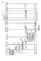
図6は、ハンドオフが行われるときに図2の様々なエンティティの間で交換される信号フローを説明する別の例示的な信号フロー図を示す。詳細には、図6は、VSNCPコンテキスト確立動作によって生じる中断ギャップを低減するためにハンドオフ段階中に交換され得る信号を説明するフロー図の例を示す。図6に示すように、604において、UE206がeHRPDへのハンドオフが必要であると判断したとき、602において、UEがE−UTRAネットワーク上で動作していることがある。ターゲットeHRPDネットワークとの部分コンテキストがあらかじめ確立されていることがある。606において、パイロット取得およびオーバーヘッド更新が実行され得る。図5とは対照的に、トラフィックチャネルが確立される前に、608において、DoSを使用してシグナリングチャネル上でeAN/ePCF212にVSNCP構成要求メッセージとともに接続要求が送信され得る。たとえば、アクセスチャネルが使用され得る。この場合、VSNCPデータパケットによって使用されるオクテットの数は、最小値に低減される必要があり得る。次いで、610において、eAN/ePCF212が、HSGW214にVSNCP構成要求メッセージを送信し得る。この時点で、612において、HSGW214は、PCRF230を用いてゲートウェイ制御セッションセットアップを実行することが可能である。次いで、614において、プロキシモバイルIP(PMIP)バインディング更新メッセージが送信され得、616において、P−GW218が、たとえば、QoSポリシーパラメータを取り出すために、PCRFインタラクションを実行し得る。次いで、618において、応答してHSGW214にPMIPバインディング確認メッセージが送信され得る。シグナリングチャネルを使用してVSNCP構成要求メッセージを送ることは、トラフィックチャネルが確立される前または間にVSNCPコンテキスト確立プロシージャが開始することを可能にし得る。このようにして、(PMIPバインディングとともに)トラフィックチャネル確立とVSNCPセットアッププロシージャとが並行して実行され得る。トラフィックチャネル確立はVSNCPセットアップおよびPMIPバインディングよりも多くの時間を要し得るので、動作を並行して行うことは、VSNCPセットアップおよびPMIPバインディングに必要とされる時間を本質的に見えなくし得る。したがって、VSNCPセットアップおよびPMIPバインディングのために必要とされる時間は、中断ギャップにさらに寄与し得ない。したがって、VSNCPコンテキスト確立がトラフィックチャネルセットアップの完了に依存する必要がなくなり得るので、シグナリングチャネル上でVSNCP構成要求メッセージを送ることは、ハンドオフプロセス中の著しい時間節約をもたらし得る。
FIG. 6 shows another exemplary signal flow diagram illustrating the signal flow exchanged between the various entities of FIG. 2 when a handoff occurs. Specifically, FIG. 6 shows an example flow diagram illustrating signals that may be exchanged during the handoff phase to reduce the break gap caused by the VSNCP context establishment operation. As shown in FIG. 6, at 604, when the
図6を続けると、608においてUE206がVSNCP構成要求を送信した後、620においてトラフィックチャネルセットアッププロシージャが実行される。トラフィックチャネルセットアップは、VSNCPコンテキスト確立動作により、ほとんどまたはまったく中断ギャップがもたらされないように、610、612、614、616、および618においてメッセージが交換されるのと同時に実行され得る。620においてトラフィックチャネルがセットアップされた後、UE206が、UE206に関連するA10セッションが利用可能であることを認識し得、622において「アクティブ開始」メッセージを送信し得、624においてA11登録応答メッセージを受信し得る。この時点で、626において、HSGW214がUE206にVSNCP構成確認メッセージを送信し得る。628において、HSGW214はまた、UE206にVSNCP構成要求メッセージを送信し得、630において、UE206は、応答してHSGW214にVSNCP構成確認メッセージを送信し得る。632において、データ転送はまた、eHRPD上で開始し得る。
Continuing with FIG. 6, after
図7Aは、VSNCPメッセージフォーマットの例を示す。上述のように、VSNCPシグナリングデータパケットのサイズを縮小すること(たとえば、必要とされるオクテットの数を低減すること)は、シグナリングチャネルを通してVSNCP構成要求を送信することを促進し得、ハンドオフ中の中断ギャップを低減するための他の処理利点を提供し得る。VSNCPパケットに関連する様々な態様は、その全体の中に参照によりここに組み込まれる、Point−to−Point Protocol(PPP)Vendor Protocolと題するRFC3772にさらに記載されている。さらに、VSNCPパケットに関連する様々な態様は、その全体の中に参照によりここに組み込まれもする、The Point−to−Point Protocol(PPP)と題するRFC1661にも記載されている。VSNCPパケットは、制御パケットのタイプを識別するために使用され得る1オクテットのコードフィールド702を含み得る。コードフィールド702は、VSNCP構成要求コード、構成確認コード、構成否定(configure-nak)コード、構成拒否(configure-reject)コード、終了要求(terminate-request)コード、終了確認(terminate-ack)コード、およびコード拒否(code-reject)コードを含み得る、7つの異なるコードを使用するように構成され得る。一態様では、構成否定コードは使用されないことがあり、このコードとともに送られるメッセージは、コード拒否メッセージが応答して送信されることがある。VSNCPパケットはさらに、要求と応答をマッチさせるために使用され得る1オクテットの識別子フィールド704を含み得る。VSNCPパケットはまた、コードフィールド、識別子フィールド、長さフィールドおよびデータフィールドを含むパケットの全長を示すために使用される2オクテットの長さフィールド706を含み得る。VSNCPパケットはまた、特定のベンダーを識別するための3オクテットのベンダー組織固有識別子(organizationally unique identifier)(OUI)708フィールドを含み得る。図7Aに示すように、メッセージの残りは、さらに以下で説明するように、データ710を送るために割り振られる。
FIG. 7A shows an example of the VSNCP message format. As described above, reducing the size of the VSNCP signaling data packet (eg, reducing the number of octets required) may facilitate sending a VSNCP configuration request over the signaling channel, during handoff Other processing advantages for reducing the interruption gap may be provided. Various aspects related to VSNCP packets are further described in RFC 3772 entitled Point-to-Point Protocol (PPP) Vendor Protocol, which is incorporated herein by reference in its entirety. Further, various aspects related to VSNCP packets are also described in RFC 1661 entitled The Point-to-Point Protocol (PPP), which is also incorporated herein by reference in its entirety. The VSNCP packet may include a one
ハンドオフアタッチのためのVSNCP構成要求メッセージを送信するとき、メッセージは、データフィールド710中で送られるいくつかの構成オプションを含む。以下に含まれる表1は、3GPP2 VSNCPの一実装で送信され得る様々な構成オプションのリストを提供する。

表1は、本開示の範囲内として企図される例および他の変形を表す。いくつかの実装では、構成オプション名は変わり得、タイプは非デシマル(non-decimal)値(たとえば、整数)によって表され得、非連続であり得、長さは変わり得、および/または有効値は示されているものよりも多くの値または少ない値を含み得る。たとえば、いくつかの実装では、5オクテットのアタッチタイプと1から6までの範囲の有効値とを有することが望ましいことがある。 Table 1 represents examples and other variations contemplated within the scope of this disclosure. In some implementations, configuration option names can vary, types can be represented by non-decimal values (eg, integers), can be non-contiguous, lengths can vary, and / or valid values May contain more or less values than those shown. For example, in some implementations it may be desirable to have an attach type of 5 octets and a valid value in the range of 1-6.
表1で分かるように、構成オプションは、VSNCP構成要求メッセージ中の多数のオクテットを占有し得、それは、ハンドオフ中の中断ギャップを増加させることに寄与し得、シグナリングチャネル上でVNSCP構成要求メッセージを送信することを困難にすることがある。上述の複数の構成オプションを送信するのではなく、ソースネットワークの構成とターゲットネットワークの構成との間の共通情報を活用し得る単一の構成オプションが提供され得る。たとえば、2つのネットワークの能力のうちの多くが共通であり得るので、ソースLTEネットワークと通信しているターゲットeHRPDネットワークによって構成オプションのうちの多くが取得され得る。 As can be seen in Table 1, the configuration option may occupy a large number of octets in the VSNCP configuration request message, which may contribute to increasing the break gap during handoff, and the VNSCP configuration request message on the signaling channel. It may be difficult to send. Rather than transmitting the multiple configuration options described above, a single configuration option may be provided that may leverage common information between the source network configuration and the target network configuration. For example, many of the configuration options may be obtained by the target eHRPD network in communication with the source LTE network, since many of the capabilities of the two networks may be common.
図7Bは、表1中の上述の構成オプションの代わりに、様々な実装に従って使用され得る単一の構成オプションの例を示す。新しい構成オプション703は、高速ハンドオフアタッチ構成オプションとして説明され得る。新しい構成オプションデータは、HSGW214がPDNゲートウェイとの接続を確立するために必要とされる構成オプションのフルセットを取得または導出することを可能にするために十分な情報を、eHRPDネットワーク中のHSGW214に提供するために、上記の表1中に記載された構成オプションからの必要なデータをカプセル化し得る。構成オプション703は、使用されている構成オプションタイプを示す1オクテットのタイプフィールド712によって識別され得る。構成オプションタイプは、現在定義されている構成オプションタイプとの重複を回避するように10進値18に設定され得る。
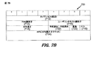
FIG. 7B shows an example of a single configuration option that may be used in accordance with various implementations instead of the configuration options described above in Table 1.
構成オプション703は、4ビットのPDN識別子フィールド714を含み得る。このフィールドの有効値は0〜14の間であるように定義され得るので、4ビットのみが必要であり得る。いくつかの構成オプションが高速アタッチ構成オプションにカプセル化される(encapsulated)ので、表1中の構成オプションによって必要とされるタイプフィールドおよび長さフィールドは省略され得る。たとえば、PDN識別子フィールドは、通常、3オクテットを必要とし得、そのうちの2オクテットは構成オプションのタイプフィールドおよび長さフィールドによって占有され得る。対照的に、構成オプション703は、他の構成オプションとともにちょうど4ビットのPDN−ID値を使用することを可能にする。構成オプション703は、複数のPDN接続の識別を可能にするために4ビットのユーザコンテキスト識別子フィールド716をさらに含み得る。構成オプション703はまた、APNフィールド724によって必要とされるオクテットの数を指定するために使用され得る4ビットのAPN長さフィールド715を含む。構成オプション703は、ネットワーク主導型QoS(network-initiated QoS)またはUE主導型QoS(UE-initiated QoS)のいずれかなど、どのタイプのサービス品質(QoS)能力をネットワークがサポートし得るかを判断するために使用され得る1ビットのベアラ制御モジュールフィールド718をさらに含み得る。さらに、緊急サービス要求があるかどうかを判断するための1ビットの緊急フィールド720が提供され得る。2つの予約済みフィールド722も含まれ得る。
さらに、APNフィールド724はまた構成オプション703メッセージ中に含まれ、UEがそれと接続することを望むパケットデータネットワーク(PDN)を識別するために使用される。表1に記載したように、APNは、合計100オクテットを必要とするように定義され得る。ここに提供する一実装によれば、APNフィールド724の長さは、(4ビットのAPN長さフィールド715が指定し得る最大値である)16オクテットに限定され得る。これは、構成オプション703によって必要とされるオクテットの最大数がメッセージの効率的な送信および処理のために十分に小さいままであることを保証するのに役立つ。さらに、APN長さフィールド734を使用することによって、APNフィールド724中のオクテットの数は変わり得、APNが16オクテット未満を使用するときに構成オプション703のために必要とされるオクテットの低減された数を可能にし得る。
In addition, the
図7Bに記載されている構成オプション703を使用することによって、残りの構成オプションが送られ得ない。HSGW214が構成オプション703をもつVNSCPメッセージを受信したとき、HSGWは、その低減されたメッセージを、PDN−GW218と通信するために必要とされるフォーマットに変換するために、部分コンテキストを使用して保持されたか、またはLTEネットワークから取り出された共通情報を使用し得る。LTEネットワークとeHRPDネットワークとの間の共通情報を使用し、構成オプションデータを構成オプション703にカプセル化し/低減することによって、VSNCP構成要求メッセージのために必要とされるバイトの総数が著しく低減される。図7Bに示すように、VSNCP構成要求メッセージ701の総サイズは、APNフィールド724のための最大値16バイトとともに、APNフィールド724なしの構成オプションの3バイトとともに図7Aに示したVSCNPメッセージフォーマットヘッダフィールドのための7バイトを含む最大値26バイトであり得る。図6に示したようにトラフィックチャネルが構成される前にシグナリングチャネル上でメッセージを送信することとともに図7Aおよび図7Bに記載した低減されたサイズの構成要求メッセージを使用することによって、VSNCPコンテキストが確立されるために必要とされる時間が、トラフィックチャネル確立のために必要とされる時間以上に余分の時間を追加することなしに達成され得るので、中断ギャップは著しく低減され得る。
By using the
図7Cは、別の実装によるVSNCPパケットデータフォーマットの例を示す。上述したように、制御パケットのタイプを識別するために使用されるコードフィールド726のために7つのコードが定義され得る。一実装によれば、構成要求メッセージとは別の追加のVSNCP制御メッセージ705を定義するために、第8のコードが追加され得る。この構成メッセージ705は、高速ハンドオフ要求メッセージとして説明され得る。メッセージフォーマットは、その場合、構成要求メッセージによって必要とされるフォーマットとは無関係に定義され得、したがって、図7Bに示した構成オプションのタイプフィールド712を指定する必要がないことがある。その結果、図7Bに示したフィールドのうちのいくつかが、1オクテットのタイプフィールド712の省略を伴って高速ハンドオフ要求メッセージ中に含まれ得る。さらに、3オクテットのOUIフィールド708も、VSNCPデータメッセージフォーマット705から省略され得る。したがって、VSNCPデータメッセージフォーマット705のためのバイトの総数は、APNフィールド742の最大値16バイトとともにVSNCPパケットヘッダと構成オプションとの4バイトの合計最大値20バイトに低減され得る。
FIG. 7C shows an example of a VSNCP packet data format according to another implementation. As described above, seven codes may be defined for the code field 726 used to identify the type of control packet. According to one implementation, an eighth code may be added to define an additional
図7Bに記載したメッセージフォーマットでは、最大値において、APNフィールド724は16バイトまでを含むことができるので、APNフィールド724はメッセージフォーマット703によって必要とされる総バイトの大部分を占有する。別の実装によれば、APNフィールド724の必要をなくすために、図4を参照しながら上記で説明した事前登録段階が、APNを事前構成するように変更され得る。より詳細には、APNとPDN−IDとの間のマッピングがUE206からHSGW214に送信され得る。ハンドオフが行われた後に、マッピングは削除され得る。次いで、以下でさらに詳細に説明するようにAPNフィールド724とAPN長さフィールド715とを含むことなしに、図6を参照しながら上記で説明したようにハンドオフが実行され得る。
In the message format described in FIG. 7B, at maximum, the
図8は、ハンドオフが行われる前に図2の様々なエンティティの間で交換される信号フローを説明する別の例示的な信号フロー図を示す。詳細には、図8は、今上述したような実装に従ってeHRPD RANとの部分コンテキストを確立するためにハンドオフが行われる前に交換され得る信号を説明するフロー図の例を示す。802において、UE206がeHRPDを通して部分コンテキストを確立することを判断した後に、UEは、804においてeHRPDセッション確立を実行し、806においてeAN/ePCF212とのデバイス認証を(たとえば、A12認証を使用して)実行する。これの後に、808において、HSGW214とのA10接続セットアップが続き得る。PPP LCPコンテキスト確立中に、810において、UEは、APNへのPDN−IDのマッピングを含んでいるLCP構成要求メッセージをHSGW214に送信し得る。812において、HSGW214がマッピングを受け付けた場合、LCP構成確認メッセージ中で値が送信される。次いで、814において、HSGW214はUE206にLCP構成要求メッセージを送信し、816において、UE206はLCP構成確認メッセージで応答する。この時点で、次いで、818a、818bおよび818cにおいて、EAP−AKA認証コンテキストが確立される。認証の後、820において、HSGW212が、加入者プロファイル、デフォルトアクセスポイント名(APN)、ネットワークアクセス識別子(NAI)、および他の必要な情報をキャッシュし得る。次いで、822において、HSGWは部分コンテキストを維持することができる。部分コンテキストが確立された後、824において、UEはE−UTRAネットワークに同調し得る。図8に示されていない他のLCPメッセージも、HSGW214にマッピングを送信するために使用され得ることを諒解されたい。たとえば、LCPエコー要求および返答が、ベンダー固有のオプションとともに使用され得、またはベンダー固有のパケットが使用され得る。
FIG. 8 shows another exemplary signal flow diagram illustrating the signal flow exchanged between the various entities of FIG. 2 before the handoff takes place. Specifically, FIG. 8 shows an example flow diagram illustrating signals that may be exchanged before a handoff is made to establish a partial context with an eHRPD RAN according to an implementation as just described above. After the
HSGWは、図8に示す事前登録段階中にAPNへのPDN−IDのマッピングを受信するように構成され得るので、ハンドオフ中に受信されたPDN識別子は関連するAPNを識別するために十分であり得る。その結果、図7Bおよび図7Cに示したメッセージフォーマットは、APNフィールドおよびAPN長さフィールドを除去するように変更され得る。 Since the HSGW may be configured to receive the PDN-ID mapping to APN during the pre-registration phase shown in FIG. 8, the PDN identifier received during handoff is sufficient to identify the associated APN. obtain. As a result, the message format shown in FIGS. 7B and 7C can be modified to remove the APN field and the APN length field.
図9は、構成要求メッセージフォーマットを説明する例を示す。図9Aおよび図9Bは、図8に示した事前登録段階など、事前登録段階での使用のために、変更されたVNSCPパケットデータフォーマットの例を示す。図9Aは、表1に記載され、および図7Bに同様に示された構成オプションの代わりに使用される単一の構成オプション901を示す。図9Aでは、APN長さフィールドおよびAPNフィールドは省略される。その結果、示されている実装では、必要とされるバイトの総数は、VSCNPメッセージフォーマットヘッダに必要とされる7バイト、および新しい構成オプション901を指定するタイプフィールド902と図7Bを参照しながら説明した他のフィールドとのための2バイトを含む9バイトであり得る。図9Bは図7Cに対応し、タイプフィールド902とOUIフィールド708との除去を可能にする、さらに提供されたVSNCP高速ハンドオフ要求メッセージを識別するための第8のコードを定義する。図9Bでは、APNフィールドおよびAPN長さフィールドはまた、図8に示した事前登録段階に関連して省略され得る。その結果、図9Bに示すように、必要とされるVSNCPメッセージフォーマットは合計3バイトであり得る。
FIG. 9 shows an example for explaining the configuration request message format. 9A and 9B show examples of modified VNSCP packet data formats for use in the pre-registration phase, such as the pre-registration phase shown in FIG. FIG. 9A shows a
図10は、ワイヤレス通信システムにおけるハンドオフの方法のプロセスフロー図を示す。ブロック1002において、方法を実装するデバイスは、第1のネットワークにアタッチし、それとのコンテキストを作成する。デバイスは、データ非アクティビティ期間中にアタッチするように構成され得る。いくつかの実装では、第1のネットワークは、第2のネットワークと比較して好適でないネットワークであり得る。ブロック1004において、第1のネットワークとの少なくとも部分コンテキストを維持しながら、第1のネットワークとの作成されたコンテキストに基づいて第2のネットワークへの接続が確立される。
FIG. 10 shows a process flow diagram of a method of handoff in a wireless communication system. In
図11は、ソースネットワークからターゲットネットワークへのワイヤレスデバイスのハンドオフに関連する情報を通信するための方法の例を示す。ブロック10−1において、UEが、シグナリングチャネルを使用して、パケットデータネットワークへの接続を確立するための要求をターゲットネットワークに送信し得る。要求は、図7Bに関して上記でさらに説明したように、VSNCP構成要求メッセージであり得る。構成要求メッセージは、上述のように単一の構成オプションメッセージを含み得る。さらに、要求は、図7CによるVSNCP高速ハンドオフ要求メッセージであり得る。いくつかの実装では、要求は、電源投入など、データ非アクティビティ期間中に送信され得る。したがって、要求は、ハンドオフの必要に先立って送信され得る。シグナリングチャネルは、たとえば、アクセスチャネルであり得、要求は、データオーバーシグナリング(DoS)を使用するアクセスチャネル上で送信され得る。ブロック10−2において、UEは、ターゲットネットワーク上でトラフィックチャネルを確立するためのプロシージャを開始し得る。ブロック10−2において、トラフィックチャネルが構成される前にパケットデータネットワークへの接続を確立するための要求が送信され得る。 FIG. 11 illustrates an example method for communicating information related to a handoff of a wireless device from a source network to a target network. In block 10-1, the UE may send a request to the target network to establish a connection to the packet data network using the signaling channel. The request may be a VSNCP configuration request message as described further above with respect to FIG. 7B. The configuration request message may include a single configuration option message as described above. Further, the request may be a VSNCP fast handoff request message according to FIG. 7C. In some implementations, the request may be sent during a data inactivity period, such as a power up. Thus, the request can be sent prior to the need for handoff. The signaling channel can be, for example, an access channel, and the request can be sent on an access channel that uses data over signaling (DoS). In block 10-2, the UE may initiate a procedure for establishing a traffic channel on the target network. In block 10-2, a request to establish a connection to the packet data network may be sent before the traffic channel is configured.
図12は、通信システムにおける様々なコンポーネントの機能ブロック図の例を示す。上記で説明したシステムおよび方法によって示される、ここにおける教示は、少なくとも1つの他のノードと通信するための様々なコンポーネントを使用するノード(たとえば、デバイス)に組み込まれ得る。図12は、ノード間の通信を促進するために使用され得るいくつかのサンプルコンポーネントを示す。詳細には、図12は、多入力多出力(MIMO)システム1200の第1のワイヤレスデバイス1210(たとえば、アクセスポイント)および第2のワイヤレスデバイス1250(たとえば、アクセス端末)の簡易ブロック図である。第1のデバイス1210では、いくつかのデータストリームのトラフィックデータが、データソース1212から送信(TX)データプロセッサ1214に提供される。
FIG. 12 shows an example functional block diagram of various components in a communication system. The teachings presented herein by the systems and methods described above may be incorporated into nodes (eg, devices) that use various components to communicate with at least one other node. FIG. 12 illustrates some sample components that can be used to facilitate communication between nodes. In particular, FIG. 12 is a simplified block diagram of a first wireless device 1210 (eg, an access point) and a second wireless device 1250 (eg, an access terminal) of a multiple-input multiple-output (MIMO)
いくつかの態様では、各データストリームは、それぞれの送信アンテナを通して送信される。TXデータプロセッサ1214は、コード化されたデータを提供するために各データストリーム用に選択された特定のコーディングスキームに基づいて、各データストリームのためにトラフィックデータをフォーマットし、コード化し、インターリーブする。
In some aspects, each data stream is transmitted through a respective transmit antenna.
各データストリームのコード化されたデータは、OFDM技法を使用してパイロットデータで多重化され得る。パイロットデータは、典型的には、知られている方法で処理され、チャネル応答を推定するために受信機システムにおいて使用され得る、既知のデータパターンである。次いで、多重化された、パイロットデータおよび各データストリームのコード化されたデータは、変調シンボルを提供するために、そのデータストリーム用に選択された特定の変調スキーム(たとえば、BPSK、QSPK、M−PSK、またはM−QAM)に基づいて変調(すなわち、シンボルマッピング)される。各データストリームのデータレート、コーディング、および変調は、プロセッサ1230によって実行される命令によって判断され得る。データメモリ1232は、プロセッサ1230またはデバイス1210の他のコンポーネントによって使用されるプログラムコード、データ、および他の情報を記憶し得る。
The coded data for each data stream may be multiplexed with pilot data using OFDM techniques. The pilot data is typically a known data pattern that is processed in a known manner and may be used at the receiver system to estimate the channel response. The multiplexed pilot data and coded data for each data stream is then sent to a specific modulation scheme (eg, BPSK, QPSP, M−) selected for that data stream to provide modulation symbols. Modulation (that is, symbol mapping) is performed based on PSK or M-QAM. The data rate, coding, and modulation for each data stream may be determined by instructions performed by processor 1230.
次いで、データストリームの変調シンボルがTX MIMOプロセッサ1220に提供され、それはさらに(たとえば、OFDM用に)その変調シンボルを処理し得る。次いで、TX MIMOプロセッサ1220は、NT個の変調シンボルストリームをNT個のトランシーバ(XCVR)1222A〜1222Tに提供する。いくつかの態様では、TX MIMOプロセッサ1220は、データストリームのシンボルと、それからシンボルが送信されているアンテナとにビームフォーミング重みを付加する。
The modulation symbols for the data stream are then provided to
各トランシーバ1222は、1つまたは複数のアナログ信号を提供するために、それぞれのシンボルストリームを受信し、処理して、さらに、MIMOチャネルを通して送信するのに適した変調された信号を提供するために、それらのアナログ信号を調整(condition)(たとえば、増幅、フィルタ処理、およびアップコンバート)する。次いで、トランシーバ1222A〜1222TからのNT個の変調された信号は、それぞれ、NT個のアンテナ1224A〜1224Tから送信される。
Each transceiver 1222 receives and processes a respective symbol stream to provide one or more analog signals and further provides a modulated signal suitable for transmission over a MIMO channel. , Condition (eg, amplify, filter, and upconvert) those analog signals. N T modulated signals from
第2のデバイス1250では、送信された変調された信号はNR個のアンテナ1252A〜1252Rによって受信され、各アンテナ1252からの受信された信号は、それぞれのトランシーバ(XCVR)1254A〜1254Rに提供される。各トランシーバ1254は、それぞれの受信された信号を調整(たとえば、フィルタ処理、増幅、およびダウンコンバート)し、サンプルを提供するために、調整された信号をデジタル化して、さらに対応する「受信された」シンボルストリームを提供するために、それらのサンプルを処理する。
At
次いで、受信(RX)データプロセッサ1260は、NT個の「検出された」シンボルストリームを提供するために、特定の受信機処理技法に基づいてNR個のトランシーバ1254からNR個の受信されたシンボルストリームを受信し、処理する。次いで、RXデータプロセッサ1260は、データストリームのトラフィックデータを回復するために、各検出されたシンボルストリームを復調し、デインターリーブし、復号する。RXデータプロセッサ1260による処理は、デバイス1210におけるTX MIMOプロセッサ1220およびTXデータプロセッサ1214によって実行される処理を補足するものである。
A receive (RX)
プロセッサ1270は、どのプリコーディング行列(以下で論じる)を使用すべきかを定期的に判断する。プロセッサ1270は、行列インデックス部とランク値部とを備える逆方向リンクメッセージを作成する(formulate)。データメモリ1272は、プロセッサ1270または第2のデバイス1250の他のコンポーネントによって使用されるプログラムコード、データおよび他の情報を記憶し得る。
The processor 1270 periodically determines which precoding matrix (discussed below) to use. The processor 1270 creates a reverse link message comprising a matrix index portion and a rank value portion.
逆方向リンクメッセージは、通信リンクおよび/または受信データストリームに関する様々なタイプの情報を備え得る。次いで、逆方向リンクメッセージは、データソース1236からいくつかのデータストリームのトラフィックデータをも受信するTXデータプロセッサ1238によって処理され、変調器1280によって変調され、トランシーバ1254A〜1254Rによって調整され、デバイス1210に戻される。
The reverse link message may comprise various types of information regarding the communication link and / or the received data stream. The reverse link message is then processed by a
デバイス1210では、第2のデバイス1250からの変調された信号は、第2のデバイス1250によって送信された逆方向リンクメッセージが抽出するために、アンテナ1224によって受信され、トランシーバ1222によって調整され、復調器(DEMOD)1240によって復調され、RXデータプロセッサ1242によって処理される。次いで、プロセッサ1230は、ビームフォーミング重みを判断するためにどのプリコーディング行列を使用すべきかを判断し、次いで、抽出されたメッセージを処理する。
At
図12はまた、通信コンポーネントが、ここに教示するアクセス制御動作を実行する1つまたは複数のコンポーネントを含み得ることを示す。たとえば、アクセス制御コンポーネント1290は、ここに教示する別のデバイス(たとえば、デバイス1250)に/から信号を送信/受信するために、デバイス1210のプロセッサ1230および/または他のコンポーネントと連携し得る。同様に、アクセス制御コンポーネント1292は、別のデバイス(たとえば、デバイス1210)に/から信号を送信/受信するために、デバイス1250のプロセッサ1270および/または他のコンポーネントと連携し得る。各デバイス1210および1250について、説明するコンポーネントのうちの2つ以上の機能が単一のコンポーネントによって提供され得ることを諒解されたい。たとえば、単一の処理コンポーネントがアクセス制御コンポーネント1290およびプロセッサ1230の機能を提供し得、単一の処理コンポーネントがアクセス制御コンポーネント1292およびプロセッサ1270の機能を提供し得る。さらに、図3を参照しながら説明した装置1200のコンポーネントは、図12のコンポーネントと統合され/に組み込まれ得る。
FIG. 12 also illustrates that a communication component can include one or more components that perform the access control operations taught herein. For example, the
図13は、別のワイヤレス通信デバイスの機能ブロック図を示す。ワイヤレス通信デバイスが、図13に示す簡略化されたワイヤレス通信デバイス1300よりも多くのコンポーネントを有し得ることを、当業者ならば諒解されよう。図示するワイヤレス通信デバイス1300は、クレームの範囲内の実装のいくつかの顕著な特徴について説明するために有用なそれらのコンポーネントのみを含む。ワイヤレス通信デバイス1300は、アタッチおよび作成回路1302と、接続回路1304とを含む。
FIG. 13 shows a functional block diagram of another wireless communication device. Those skilled in the art will appreciate that a wireless communication device may have more components than the simplified
アタッチおよび作成回路1302は、データ非アクティビティ期間中に、第1のネットワークにアタッチし、それとのコンテキストを作成するように構成され得る。アタッチおよび作成回路1902は、アンテナ、トランシーバ、およびデジタル信号プロセッサのうちの1つまたは複数を含み得る。いくつかの実装では、アタッチし、作成するための手段は、アタッチおよび作成回路1302を含み得る。 Attach and create circuit 1302 may be configured to attach to and create a context with the first network during data inactivity. Attach and create circuit 1902 may include one or more of an antenna, a transceiver, and a digital signal processor. In some implementations, means for attaching and creating may include an attach and creation circuit 1302.
接続回路1304は、第1のネットワークとの少なくとも部分コンテキストを維持しながら、第1のネットワークとの作成されたコンテキストに基づいて第2のネットワークに接続するように構成され得る。接続回路1304は、アンテナ、トランシーバ、およびデジタル信号プロセッサのうちの1つまたは複数を含み得る。いくつかの実装では、接続するための手段は、接続回路1304を含む。 The connection circuit 1304 may be configured to connect to the second network based on the created context with the first network while maintaining at least a partial context with the first network. The connection circuit 1304 may include one or more of an antenna, a transceiver, and a digital signal processor. In some implementations, the means for connecting includes a connection circuit 1304.
図14は、ワイヤレス通信システムにおけるノンオプティマイズド・ハンドオフのための例示的なプロセスフローを示す。フローの実装は、上述の方法またはデバイスの1つまたは複数を含み得る。ブロック1402において、ネットワークアクセスを望むデバイスは、電源投入時などのデータ非アクティビティ期間中にある。デバイスは、たとえば、モバイルフォンであり得る。ブロック1404において、デバイスは、eHRPDネットワークなど、第1のネットワークにアタッチし、それとのコンテキストを確立する。eHRPDネットワークは、デバイスのための好適なネットワークではないことがある。デバイスは、複数の好適でないネットワークとアタッチし、それとのコンテキストを確立し得る。しかしながら、明確にするため、第1の好適でないネットワークと第2の好適なネットワークとを含む実装が説明される。
FIG. 14 illustrates an example process flow for non-optimized handoff in a wireless communication system. The implementation of the flow may include one or more of the methods or devices described above. At
ブロック1406において、デバイスは、LTEネットワークなど、第2のネットワークにアタッチし、それとのコンテキストを確立する。LTEネットワークは、eHRPDネットワークと比較して好適なネットワークであり得る。ブロック1408において、デバイスは、第2のネットワークを介して通信を開始する。デバイスは、一般に、1つのアクティブコンテキストを有し得るので、第1のネットワークとの元のコンテキストは休止状態(dormant)である。並行して、決定ブロック1410において、第1のネットワークとのフルコンテキストが期限切れになり得る。たとえば、いくつかの実装では、eHRPD接続が使用されない場合、たとえば、ネットワークリソースを節約するのを助けるために、リンクの全部または一部分が閉じられ得る。第1のネットワークのフルコンテキストが期限切れになっていない場合、フローはループし続け、周期的に有効期限について検査する。第1のネットワークのフルコンテキストが期限切れになった場合、ブロック1412において、第1のネットワークとの部分コンテキストが維持される。たとえば、eHRPDアクセスノードを介したデバイスからHRPDゲートウェイへのリンクなど、デバイスへのeHRPDネットワークリンクの一部分が維持され得、ゲートウェイからIPアンカーへのリンクはデバイスに対して閉じられ得る。したがって、いくつかの実装では、部分コンテキストは、ネットワーク用のゲートウェイ(たとえば、HRPDゲートウェイ)によって維持され得る。
At
決定ブロック1414において、第2のネットワークへの接続が維持される限り、通信は継続する。決定ブロック1414が第2のネットワークへの接続がまだ有効(alive)であると判断した場合、フローはブロック1410に戻る。決定ブロック1414が、(たとえば、劣悪なワイヤレス信号状態により)接続がドロップされたと判断した場合、フローはブロック1416に続く。ブロック1416において、デバイスは、シグナリングチャネルを介して第1のネットワークに回復要求を送信する。シグナリングチャネルを使用することによって、回復プロセスは、ネットワークとのトラフィックチャネルを確立した後に回復要求を送る場合よりもすぐに進み得る。ブロック1418において、トラフィックチャネルは第1のネットワークのために取得される。この時点で、ブロック1420において、第1のネットワーク上でデバイスのためのコンテキストが回復され、通信が継続し得る。このようにして、第2のネットワークから第1のネットワークへのハンドオフは、部分コンテキストが使用されない実装においてよりもより効率的な方法で達成される。さらに、ハンドオフは、コンテキストを回復することが、コンテキストを回復するより前にトラフィックチャネルを確立することに依存する実装においてよりも効率的に達成される。
In
ここにおける「第1」、「第2」などの名称を使用した要素への言及は、それらの要素の数量または順序を概括的に限定するものでないことを理解されたい。むしろ、これらの名称は、ここにおいて2つ以上の要素またはある要素の複数の例を区別する便利な方法として使用され得る。したがって、第1および第2の要素への言及は、そこで2つの要素のみが使用され得ること、または第1の要素が何らかの方法で第2の要素に先行しなければならないことを意味するものではない。また、別段の規定がない限り、要素のセットは1つまたは複数の要素を含み得る。 It should be understood that references herein to elements using names such as “first”, “second”, etc. do not generally limit the quantity or order of those elements. Rather, these names may be used herein as a convenient way to distinguish between two or more elements or examples of an element. Thus, a reference to the first and second elements does not mean that only two elements can be used there, or that the first element must precede the second element in some way. Absent. Also, unless otherwise specified, a set of elements may include one or more elements.
情報および信号は多種多様な技術および技法のいずれかを使用して表され得ることを、当業者なら理解されよう。たとえば、上記の説明全体にわたって言及され得るデータ、命令、コマンド、情報、信号、ビット、シンボル、およびチップは、電圧、電流、電磁波、磁場または磁性粒子、光場(optical fields)または光学粒子、あるいはそれらの任意の組合せによって表され得る。 Those of skill in the art will understand that information and signals may be represented using any of a variety of different technologies and techniques. For example, data, instructions, commands, information, signals, bits, symbols, and chips that may be referred to throughout the above description are voltages, currents, electromagnetic waves, magnetic fields or magnetic particles, optical fields or optical particles, or It can be represented by any combination thereof.
さらに、ここに開示された態様に関連して説明した様々な実例となる論理ブロック、モジュール、プロセッサ、手段、回路、およびアルゴリズムステップのいずれかは、電子ハードウェア(たとえば、ソースコーディングまたは何らかの他の技法を使用して設計され得る、デジタル実装、アナログ実装、またはそれら2つの組合せ)、命令を組み込んだ様々な形態のプログラムまたは設計コード(便宜上、ここでは「ソフトウェア」または「ソフトウェアモジュール」と呼ぶことがある)、あるいは両方の組合せとして実装され得ることを当業者は諒解されよう。ハードウェアとソフトウェアのこの互換性を明確に示すために、様々な実例となるコンポーネント、ブロック、モジュール、回路、およびステップが、上記では概してそれらの機能に関して説明された。そのような機能がハードウェアとして実装されるか、ソフトウェアとして実装されるかは、特定のアプリケーションおよび全体的なシステムに課された設計制約に依存する。当業者は、説明した機能を特定のアプリケーションごとに様々な方法で実装し得るが、そのような実装の決定は、本開示の範囲からの逸脱(departure)を生じるものと解釈すべきではない。 Moreover, any of the various illustrative logic blocks, modules, processors, means, circuits, and algorithm steps described in connection with the aspects disclosed herein may be implemented by electronic hardware (eg, source coding or some other Digital implementation, analog implementation, or a combination of the two, which can be designed using techniques, various forms of programs or design code incorporating instructions (referred to herein as “software” or “software modules” for convenience) Those skilled in the art will appreciate that they may be implemented as a combination of both. To clearly illustrate this interchangeability of hardware and software, various illustrative components, blocks, modules, circuits, and steps have been described above generally in terms of their functionality. Whether such functionality is implemented as hardware or software depends upon the particular application and design constraints imposed on the overall system. Those skilled in the art may implement the described functionality in a variety of ways for each particular application, but such implementation decisions should not be construed as causing departure from the scope of the present disclosure.
ここに開示した態様に関連して、および図1〜図12に関して説明した様々な実例となる論理ブロック、モジュール、および回路は、集積回路(IC)、アクセス端末、またはアクセスポイント内に実装され得るか、またはそれらによって実行され得る。ICは、汎用プロセッサ、デジタル信号プロセッサ(DSP)、特定用途向け集積回路(ASIC)、フィールドプログラマブルゲートアレイ(FPGA)もしくは他のプログラマブル論理デバイス、個別ゲートもしくはトランジスタ論理、個別ハードウェアコンポーネント、電気コンポーネント、光学コンポーネント、機械コンポーネント、またはここに説明する機能を実行するように設計されたそれらの任意の組合せを含み得、IC内に、ICの外部に、またはその両方に存在する(reside)コードまたは命令を実行し得る。論理ブロック、モジュール、および回路は、ネットワーク内またはデバイス内の様々なコンポーネントと通信するためにアンテナおよび/またはトランシーバを含み得る。汎用プロセッサはマイクロプロセッサであり得るが、代替として、プロセッサは、任意の従来のプロセッサ、コントローラ、マイクロコントローラ、または状態機械であり得る。プロセッサはまた、コンピューティングデバイスの組合せ、たとえば、DSPとマイクロプロセッサとの組合せ、複数のマイクロプロセッサ、DSPコアと連結する1つまたは複数のマイクロプロセッサ、あるいは任意の他のそのような構成として実装され得る。モジュールの機能は、ここに教示した方法とは別の何らかの方法で実装され得る。(たとえば、添付の図の1つまたは複数に関して)ここに説明した機能は、いくつかの態様では、添付のクレームにおいて同様に指定された「手段(means for)」機能に対応し得る。 Various illustrative logic blocks, modules, and circuits described in connection with the aspects disclosed herein and with respect to FIGS. 1-12 may be implemented within an integrated circuit (IC), access terminal, or access point. Or can be performed by them. ICs include general purpose processors, digital signal processors (DSPs), application specific integrated circuits (ASICs), field programmable gate arrays (FPGAs) or other programmable logic devices, individual gate or transistor logic, individual hardware components, electrical components, Code or instructions that may include optical components, mechanical components, or any combination thereof designed to perform the functions described herein, residing in the IC, external to the IC, or both Can be performed. The logic blocks, modules, and circuits may include antennas and / or transceivers to communicate with various components in the network or device. A general purpose processor may be a microprocessor, but in the alternative, the processor may be any conventional processor, controller, microcontroller, or state machine. The processor is also implemented as a combination of computing devices, eg, a combination of a DSP and a microprocessor, a plurality of microprocessors, one or more microprocessors coupled to a DSP core, or any other such configuration. obtain. The functionality of the module may be implemented in some way other than that taught herein. The functions described herein (eg, with respect to one or more of the accompanying figures) may correspond in some aspects to “means for” functions similarly specified in the appended claims.
ソフトウェアで実装した場合、機能は、1つまたは複数の命令またはコードとしてコンピュータ可読媒体上に記憶され得るか、あるいはコンピュータ可読媒体を通して送信され得る。ここに開示した方法またはアルゴリズムのステップは、コンピュータ可読媒体上に存在し得る、プロセッサ実行可能ソフトウェアモジュールで実装され得る。コンピュータ可読媒体は、ある場所から別の場所にコンピュータプログラムを転送することを可能にされ得る任意の媒体を含む、コンピュータ記憶媒体と通信媒体の両方を含む。記憶媒体は、コンピュータによってアクセスされ得る任意の利用可能な媒体であり得る。限定ではなく例として、そのようなコンピュータ可読媒体は、RAM、ROM、EEPROM、CD−ROMまたは他の光ディスクストレージ、磁気ディスクストレージまたは他の磁気ストレージデバイス、あるいは命令またはデータ構造の形態で所望のプログラムコードを記憶するために使用され得、コンピュータによってアクセスされ得る、任意の他の媒体を含み得る。また、いかなる接続もコンピュータ可読媒体と適切に呼ばれ得る。ここに使用するディスク(disk)およびディスク(disc)は、コンパクトディスク(disc)(CD)、レーザーディスク(登録商標)(disc)、光ディスク(disc)、デジタル多用途ディスク(disc)(DVD)、フロッピー(登録商標)ディスク(disk)、およびブルーレイ(登録商標)ディスク(disc)を含み、この場合、ディスク(disk)は、通常、データを磁気的に再生し(reproduce)、ディスク(disc)は、データをレーザーで光学的に再生する(reproduce)。上記の組合せもコンピュータ可読媒体の範囲内に含めるべきである。さらに、方法またはアルゴリズムの動作は、コンピュータプログラム製品に組み込まれ得る、機械可読媒体およびコンピュータ可読媒体上のコードおよび命令の1つまたは任意の組合せ、あるいはそのセットとして存在し得る。 If implemented in software, the functions may be stored on or transmitted over as one or more instructions or code on a computer-readable medium. The method or algorithm steps disclosed herein may be implemented in a processor-executable software module that may reside on a computer-readable medium. Computer-readable media includes both computer storage media and communication media including any medium that may be enabled to transfer a computer program from one place to another. A storage media may be any available media that can be accessed by a computer. By way of example, and not limitation, such computer-readable media may be RAM, ROM, EEPROM, CD-ROM or other optical disk storage, magnetic disk storage or other magnetic storage device, or desired program in the form of instructions or data structures. It can include any other medium that can be used to store code and that can be accessed by a computer. Also, any connection may be properly referred to as a computer readable medium. The disc and disc used here are a compact disc (CD), a laser disc (registered trademark) (disc), an optical disc (disc), a digital versatile disc (DVD), Including a floppy disk and a Blu-ray disk, where the disk typically reproduces data magnetically and the disk is Reproduce data optically with laser. Combinations of the above should also be included within the scope of computer-readable media. Further, the operation of the method or algorithm may exist as one or any combination or set of codes and instructions on a machine-readable medium and computer-readable medium that may be incorporated into a computer program product.
任意の開示されたプロセス中のステップの任意の特定の順序または階層(hierarchy)はサンプル手法の一例であることを理解されたい。設計プリファレンスに基づいて、プロセス中のステップの特定の順序または階層は本開示の範囲内のまま再構成され得ることを理解されたい。添付の方法クレームは、様々なステップの要素をサンプル順序で提示したものであり、提示された特定の順序または階層に限定されるものではない。 It should be understood that any particular order or hierarchy of steps in any disclosed process is an example of a sample approach. It should be understood that based on design preferences, a particular order or hierarchy of steps in the process may be reconfigured while remaining within the scope of this disclosure. The accompanying method claims present elements of the various steps in a sample order, and are not limited to the specific order or hierarchy presented.
本開示で説明する実装への様々な修正は当業者には容易に明らかであり得、ここに定義した一般的な原理は、本開示の精神または範囲から逸脱することなく他の実装に適用され得る。したがって、本開示は、ここに示した実装に限定されるものではなく、ここに開示するクレーム、原理および新しい特徴に一致する、最も広い範囲を与られるべきである。「例示的」という単語は、ここではもっぱら「例、事例、または例示の働きをすること」を意味するために使用される。ここに「例示的」と記載されたいかなる実施も、必ずしも他の実装よりも好ましいまたは有利であると解釈されるべきではない。 Various modifications to the implementations described in this disclosure may be readily apparent to those skilled in the art, and the general principles defined herein may be applied to other implementations without departing from the spirit or scope of this disclosure. obtain. Accordingly, the present disclosure is not limited to the implementations shown herein but is to be accorded the widest scope consistent with the claims, principles and new features disclosed herein. The word "exemplary" is used herein exclusively to mean "serving as an example, instance, or illustration." Any implementation described herein as "exemplary" is not necessarily to be construed as preferred or advantageous over other implementations.
また、別個の実装に関して本明細書で説明されたいくつかの特徴は、単一の実装において組合せで実装され得る。また、逆に、単一の実装に関して説明された様々な特徴は、複数の実装において別個に、あるいは任意の適切なサブコンビネーションで実装され得る。その上、特徴は、いくつかの組合せで働くものとして上記で説明され得、初めにそのようにクレームされることさえあるが、クレームされる組合せからの1つまたは複数の特徴は、場合によってはその組合せから削除され得、クレームされる組合せは、サブコンビネーション、またはサブコンビネーションの変形に向けられ得る。 Also, some features described herein with respect to separate implementations can be implemented in combination in a single implementation. Conversely, the various features described with respect to a single implementation may be implemented separately in multiple implementations or in any suitable sub-combination. Moreover, a feature may be described above as working in several combinations and may even be so claimed initially, but one or more features from the claimed combination may in some cases The combinations that can be deleted from the combination and that are claimed can be directed to sub-combinations, or variations of sub-combinations.
同様に、動作は特定の順序で図面に示されているが、これは、望ましい結果を達成するために、そのような動作が、示される特定の順序でまたは順番に実行されることを、あるいはすべての図示の動作が実行されることを必要とするものとして理解されるべきでない。いくつかの状況では、マルチタスキングおよび並列処理が有利であり得る。その上、上記で説明した実装における様々なシステムコンポーネントの分離は、すべての実装においてそのような分離を必要とするものとして理解されるべきでなく、説明するプログラムコンポーネントおよびシステムは、概して、単一のソフトウェア製品において互いに一体化されるか、または複数のソフトウェア製品にパッケージングされ得ることを理解されたい。さらに、他の実装が以下のクレームの範囲内にある。場合によっては、クレームに記載のアクションは、異なる順序で実行され得、依然として望ましい結果を達成することができる。
以下に、本願出願の当初の特許請求の範囲に記載された発明を付記する。
[1]下記を備える、ワイヤレス通信システムにおけるハンドオフの方法、
データ非アクティビティ期間中に、第1のネットワークにアタッチし、それとのコンテキストを作成することであって、前記第1のネットワークが第2のネットワークと比較して好適でないネットワークである、アタッチし、コンテキストを作成することと、
前記第1のネットワークとの少なくとも部分コンテキストを維持しながら、前記第1のネットワークとの作成された前記コンテキストに基づいて前記第2のネットワークに接続すること。
[2]前記第2のネットワークの非可用性に基づいて前記第2のネットワークから前記第1のネットワークに切り替えることをさらに備える、[1]に記載の方法。
[3]切り替えることが、前記元のコンテキストを回復することを備える、[2]に記載の方法。
[4]前記フルコンテキストを回復することが、
シグナリングチャネルを使用して、パケットデータネットワークへの接続を確立するための要求を前記第1のネットワークに送信することと、
前記第1のネットワーク上でトラフィックチャネルを確立することと
を備え、
ここにおいて前記トラフィックチャネルが確立される前に、前記パケットデータネットワークへの接続を確立するための前記要求が送信される、[3]に記載の方法。
[5]前記シグナリングチャネル上で前記要求を前記送信することが、データオーバーシグナリングを使用して前記要求を送信することを備え、ここにおいて前記シグナリングチャネルがアクセスチャネルを備える、[4]に記載の方法。
[6]パケットデータネットワークへの接続を確立するための前記要求が単一構成オプションメッセージをさらに備え、前記単一構成オプションメッセージが、少なくともアクセスポイント名とアクセスポイント名の長さとを備える、[4]に記載の方法。
[7]前記単一構成オプションメッセージが、構成オプションタイプ、パケットデータネットワーク識別子、ユーザコンテキスト識別子、緊急インジケータ、およびベアラ制御モードのうちの少なくとも1つをさらに備える、[6]に記載の方法。
[8]パケットデータネットワークへの接続を確立するための前記要求が、ベンダー固有のネットワーク制御プロトコル高速ハンドオフ要求メッセージをさらに備える、[4]に記載の方法。
[9]前記方法が、
前記部分コンテキストが確立されるときに、少なくとも1つのアクセスポイント名への少なくとも1つのパケットデータネットワーク識別子のマッピングを送信することをさらに備える、[4]に記載の方法。
[10]前記コンテキストを作成することが、パケットデータネットワーク識別子を含むパケットデータネットワークへの接続を確立するための要求を送信することを備え、ここにおいて前記ターゲットネットワークが、前記パケットデータネットワーク識別子に関連するアクセスポイント名を判断するために前記マッピングを使用するように構成された、[9]に記載の方法。
[11]前記第2のネットワークが、ロングタームエボリューション無線アクセス技術を使用するように構成されたネットワークを備え、ここにおいて前記第1のネットワークが、発展型高速パケットデータ無線アクセス技術を使用するように構成されたネットワークを備える、[1]に記載の方法。
[12]通信ネットワークにおいて作用するワイヤレス通信装置であって、前記装置は下記を備える、
データ非アクティビティ期間中に、第1のネットワークにアタッチし、それとのコンテキストを作成することであって、前記第1のネットワークが第2のネットワークと比較して好適でないネットワークである、アタッチし、コンテキストを作成することと、
前記第1のネットワークとの少なくとも部分コンテキストを維持しながら、前記第1のネットワークとの作成された前記コンテキストに基づいて前記第2のネットワークに接続することと
を行うように構成されたプロセッサ。
[13]前記プロセッサが、前記第2のネットワークの非可用性に基づいて前記第2のネットワークから前記第1のネットワークに切り替えるようにさらに構成された、[12]に記載のワイヤレス通信装置。
[14]切り替えることが、前記元のコンテキストを回復することを備える、[13]に記載のワイヤレス通信装置。
[15]前記元のコンテキストを回復することが、
シグナリングチャネルを使用して、パケットデータネットワークへの接続を確立するための要求を前記第1のネットワークに送信することと、
前記第1のネットワーク上でトラフィックチャネルを確立することと
を備え、
ここにおいて前記トラフィックチャネルが確立される前に、前記パケットデータネットワークへの接続を確立するための前記要求が送信される、[14]に記載のワイヤレス通信装置。
[16]前記プロセッサが、データオーバーシグナリングを使用して、前記パケットデータネットワークへの接続を確立するための前記要求を送信するように構成され、ここにおいて前記シグナリングチャネルがアクセスチャネルを備える、[15]に記載のワイヤレス通信装置。
[17]パケットデータネットワークへの接続を確立するための前記要求が単一構成オプションメッセージをさらに備え、ここにおいて前記単一構成オプションメッセージが、少なくともアクセスポイント名とアクセスポイント名の長さとを備える、[15]に記載のワイヤレス通信装置。
[18]前記単一構成オプションメッセージが、構成オプションタイプ、パケットデータネットワーク識別子、ユーザコンテキスト識別子、緊急インジケータ、およびベアラ制御モードのうちの少なくとも1つをさらに備える、[17]に記載のワイヤレス通信装置。
[19]パケットデータネットワークへの接続を確立するための前記要求が、ベンダー固有のネットワーク制御プロトコル高速ハンドオフ要求メッセージをさらに備える、[15]に記載のワイヤレス通信装置。
[20]前記プロセッサが、
前記部分コンテキストが確立されるときに、少なくとも1つのアクセスポイント名への少なくとも1つのパケットデータネットワーク識別子のマッピングを送信するようにさらに構成された、[15]に記載のワイヤレス通信装置。
[21]パケットデータネットワークへの接続を確立するための前記要求が、パケットデータネットワーク識別子を備え、ここにおいて前記第1のネットワークが、前記パケットデータネットワーク識別子に関連するアクセスポイント名を判断するために前記マッピングを使用するように構成された、[20]に記載のワイヤレス通信装置。
[22]前記第2のネットワークが、ロングタームエボリューション無線アクセス技術を使用するように構成されたネットワークを備え、ここにおいて前記第1のネットワークが、発展型高速パケットデータ無線アクセス技術を使用するように構成されたネットワークを備える、[12]に記載のワイヤレス通信装置。
[23]通信ネットワークにおいて作用するワイヤレス通信装置であって、前記装置は下記を備える、
データ非アクティビティ期間中に、第1のネットワークにアタッチし、それとのコンテキストを作成するための手段であって、前記第1のネットワークが前記第2のネットワークと比較して好適でないネットワークである、アタッチし、コンテキストを作成するための手段と、
前記第1のネットワークとの少なくとも部分コンテキストを維持しながら、前記第1のネットワークとの作成された前記コンテキストに基づいて前記第2のネットワークに接続するための手段。
[24]前記第2のネットワークの非可用性に基づいて前記第2のネットワークから前記第1のネットワークに切り替えるための手段をさらに備える、[23]に記載のワイヤレス通信装置。
[25]前記切り替えるための手段が、前記元のコンテキストを回復するための手段に結合される、[24]に記載のワイヤレス通信装置。
[26]前記復元するための手段が、
シグナリングチャネルを使用して、パケットデータネットワークへの接続を確立するための要求を前記第1のネットワークに送信するための手段と、
前記第1のネットワーク上でトラフィックチャネルの前記確立を開始するための手段と
を備え、
ここにおいて前記トラフィックチャネルが確立される前に、前記パケットデータネットワークへの接続を確立するための前記要求が送信される、[25]に記載のワイヤレス通信装置。
[27]パケットデータネットワークへの接続を確立するための要求を送信するための前記手段が、データオーバーシグナリングを使用して前記要求を送信するための手段をさらに備え、ここにおいて前記シグナリングチャネルがアクセスチャネルを備える、[26]に記載のワイヤレス通信装置。
[28]パケットデータネットワークへの接続を確立するための前記要求が単一構成オプションメッセージをさらに備え、ここにおいて前記単一構成オプションメッセージが、少なくともアクセスポイント名とアクセスポイント名の長さとを備える、[26]に記載のワイヤレス通信装置。
[29]前記単一構成オプションメッセージが、構成オプションタイプ、パケットデータネットワーク識別子、ユーザコンテキスト識別子、緊急インジケータ、およびベアラ制御モードのうちの少なくとも1つをさらに備える、[28]に記載のワイヤレス通信装置。
[30]パケットデータネットワークへの接続を確立するための前記要求が、ベンダー固有のネットワーク制御プロトコル高速ハンドオフ要求メッセージをさらに備える、[26]に記載のワイヤレス通信装置。
[31]前記装置が、
前記部分コンテキストが確立されるときに、少なくとも1つのアクセスポイント名への少なくとも1つのパケットデータネットワーク識別子のマッピングを送信するための手段をさらに備える、[26]に記載のワイヤレス通信装置。
[32]パケットデータネットワークへの接続を確立するための前記要求が、パケットデータネットワーク識別子を備え、ここにおいて前記ターゲットネットワークが、前記パケットデータネットワーク識別子に関連するアクセスポイント名を判断するために前記マッピングを使用するように構成された、[31]に記載のワイヤレス通信装置。
[33]前記第2のネットワークが、ロングタームエボリューション無線アクセス技術を使用するように構成されたネットワークを備え、ここにおいて前記第1のネットワークが、発展型高速パケットデータ無線アクセス技術を使用するように構成されたネットワークを備える、[23]に記載のワイヤレス通信装置。
[34]データ非アクティビティ期間中に、第1のネットワークにアタッチし、それとのコンテキストを作成することであって、前記第1のネットワークが第2のネットワークと比較して好適でないネットワークである、アタッチし、コンテキストを作成することをコンピュータに行わせるためのコードと、
前記第1のネットワークとの少なくとも部分コンテキストを維持しながら、前記第1のネットワークとの作成された前記コンテキストに基づいて前記第2のネットワークに接続することをコンピュータに行わせるためのコードと
を備えるコンピュータ可読媒体
を備える、コンピュータプログラム製品。
[35]コンピュータに前記第2のネットワークの非可用性に基づいて前記第2のネットワークから前記第1のネットワークに切り替えさせるためのコードをさらに備える、[34]に記載のコンピュータプログラム製品。
[36]切り替えることが、前記元のコンテキストを回復することを備える、[35]に記載のコンピュータプログラム製品。
[37]前記コンピュータ可読媒体が、
コンピュータに、シグナリングチャネルを使用して、パケットデータネットワークへの接続を確立するための要求を前記第1のネットワークに送信させるためのコードと、
コンピュータに前記第1のネットワーク上でトラフィックチャネルの前記確立を開始させるためのコードと
をさらに備え、
前記トラフィックチャネルが確立される前に、前記パケットデータネットワークへの接続を確立するための前記要求が送信される、[36]に記載のコンピュータプログラム製品。
[38]コンピュータにシグナリングチャネル上で前記要求を送信させるための前記コードが、データオーバーシグナリングを使用して前記要求を送信するためのコードをさらに備え、ここにおいて前記シグナリングチャネルがアクセスチャネルを備える、[37]に記載のコンピュータプログラム製品。
[39]パケットデータネットワークへの接続を確立するための前記要求が単一構成オプションメッセージをさらに備え、ここにおいて前記単一構成オプションメッセージが、少なくともアクセスポイント名とアクセスポイント名の長さとを備える、[37]に記載のコンピュータプログラム製品。
[40]前記単一構成オプションメッセージが、構成オプションタイプ、パケットデータネットワーク識別子、ユーザコンテキスト識別子、緊急インジケータ、およびベアラ制御モードのうちの少なくとも1つをさらに備える、[39]に記載のコンピュータプログラム製品。
[41]パケットデータネットワークへの接続を確立するための前記要求が、ベンダー固有のネットワーク制御プロトコル高速ハンドオフ要求メッセージをさらに備える、[37]に記載のコンピュータプログラム製品。
[42]前記コンピュータ可読媒体が、
前記部分コンテキストが確立されるときに、少なくとも1つのアクセスポイント名への少なくとも1つのパケットデータネットワーク識別子のマッピングを送信するためのコードをさらに備える、[37]に記載のコンピュータプログラム製品。
[43]パケットデータネットワークへの接続を確立するための前記要求が、パケットデータネットワーク識別子を備え、ここにおいて前記ターゲットネットワークが、前記パケットデータネットワーク識別子に関連するアクセスポイント名を判断するために前記マッピングを使用するように構成された、[42]に記載のコンピュータプログラム製品。
[44]前記第2のネットワークが、ロングタームエボリューション無線アクセス技術を使用するように構成されたネットワークを備え、ここにおいて前記第1のネットワークが、発展型高速パケットデータ無線アクセス技術を使用するように構成されたネットワークを備える、[34]に記載のコンピュータプログラム製品。
Similarly, operations are shown in the drawings in a particular order, which means that such operations are performed in the particular order shown or in order to achieve the desired result, or It should not be understood as requiring that all illustrated operations be performed. In some situations, multitasking and parallel processing may be advantageous. Moreover, the separation of various system components in the implementations described above should not be understood as requiring such separation in all implementations, and the described program components and systems are generally single. It should be understood that the software products may be integrated with each other or packaged into multiple software products. In addition, other implementations are within the scope of the following claims. In some cases, the actions recited in the claims can be performed in a different order and still achieve desirable results.
Hereinafter, the invention described in the scope of claims of the present application will be appended.
[1] A handoff method in a wireless communication system, comprising:
Attach to the first network and create a context with it during the data inactivity period, wherein the first network is a less preferred network compared to the second network Creating
Connecting to the second network based on the created context with the first network while maintaining at least a partial context with the first network.
[2] The method according to [1], further comprising switching from the second network to the first network based on non-availability of the second network.
[3] The method of [2], wherein switching comprises recovering the original context.
[4] recovering the full context,
Using a signaling channel to send a request to the first network to establish a connection to a packet data network;
Establishing a traffic channel on the first network;
With
The method according to [3], wherein the request for establishing a connection to the packet data network is transmitted before the traffic channel is established.
[5] The transmission according to [4], wherein the transmitting the request on the signaling channel comprises transmitting the request using data over signaling, wherein the signaling channel comprises an access channel. Method.
[6] The request for establishing a connection to a packet data network further comprises a single configuration option message, the single configuration option message comprising at least an access point name and an access point name length. ] Method.
[7] The method of [6], wherein the single configuration option message further comprises at least one of a configuration option type, a packet data network identifier, a user context identifier, an emergency indicator, and a bearer control mode.
[8] The method of [4], wherein the request to establish a connection to a packet data network further comprises a vendor specific network control protocol fast handoff request message.
[9] The method includes:
The method of [4], further comprising transmitting a mapping of at least one packet data network identifier to at least one access point name when the partial context is established.
[10] Creating the context comprises sending a request to establish a connection to a packet data network including a packet data network identifier, wherein the target network is associated with the packet data network identifier The method of [9], configured to use the mapping to determine an access point name to perform.
[11] The second network comprises a network configured to use a long term evolution radio access technology, wherein the first network uses an advanced high-speed packet data radio access technology. The method of [1], comprising a configured network.
[12] A wireless communication device operating in a communication network, the device comprising:
Attach to the first network and create a context with it during the data inactivity period, wherein the first network is a less preferred network compared to the second network Creating
Connecting to the second network based on the created context with the first network while maintaining at least a partial context with the first network;
A processor configured to do.
[13] The wireless communication device according to [12], wherein the processor is further configured to switch from the second network to the first network based on non-availability of the second network.
[14] The wireless communication device of [13], wherein switching comprises recovering the original context.
[15] recovering the original context;
Using a signaling channel to send a request to the first network to establish a connection to a packet data network;
Establishing a traffic channel on the first network;
With
The wireless communication device of [14], wherein the request for establishing a connection to the packet data network is transmitted before the traffic channel is established.
[16] The processor is configured to send the request to establish a connection to the packet data network using data over signaling, wherein the signaling channel comprises an access channel. ] The wireless communication apparatus as described in.
[17] The request for establishing a connection to a packet data network further comprises a single configuration option message, wherein the single configuration option message comprises at least an access point name and an access point name length. [15] The wireless communication device according to [15].
[18] The wireless communication apparatus of [17], wherein the single configuration option message further comprises at least one of a configuration option type, a packet data network identifier, a user context identifier, an emergency indicator, and a bearer control mode. .
[19] The wireless communications apparatus of [15], wherein the request to establish a connection to a packet data network further comprises a vendor specific network control protocol fast handoff request message.
[20] The processor
The wireless communications apparatus of [15], further configured to transmit a mapping of at least one packet data network identifier to at least one access point name when the partial context is established.
[21] The request for establishing a connection to a packet data network comprises a packet data network identifier, wherein the first network determines an access point name associated with the packet data network identifier. The wireless communication device of [20], configured to use the mapping.
[22] The second network comprises a network configured to use a long term evolution radio access technology, wherein the first network uses an evolved high-speed packet data radio access technology. The wireless communication device according to [12], comprising a configured network.
[23] A wireless communication device operating in a communication network, the device comprising:
A means for attaching to and creating a context with a first network during a period of data inactivity, wherein the first network is an unsuitable network compared to the second network And means for creating a context;
Means for connecting to the second network based on the created context with the first network while maintaining at least a partial context with the first network.
[24] The wireless communication device according to [23], further comprising means for switching from the second network to the first network based on non-availability of the second network.
[25] The wireless communication apparatus of [24], wherein the means for switching is coupled to means for recovering the original context.
[26] The means for restoring
Means for transmitting to the first network a request to establish a connection to a packet data network using a signaling channel;
Means for initiating the establishment of a traffic channel on the first network;
With
The wireless communication device of [25], wherein the request to establish a connection to the packet data network is transmitted before the traffic channel is established.
[27] The means for transmitting a request to establish a connection to a packet data network further comprises means for transmitting the request using data over signaling, wherein the signaling channel is accessed. The wireless communication device according to [26], comprising a channel.
[28] The request to establish a connection to a packet data network further comprises a single configuration option message, wherein the single configuration option message comprises at least an access point name and an access point name length. [26] The wireless communication device according to [26].
[29] The wireless communication apparatus of [28], wherein the single configuration option message further comprises at least one of a configuration option type, a packet data network identifier, a user context identifier, an emergency indicator, and a bearer control mode. .
[30] The wireless communications apparatus of [26], wherein the request to establish a connection to a packet data network further comprises a vendor specific network control protocol fast handoff request message.
[31] The device
The wireless communications apparatus of [26], further comprising means for transmitting a mapping of at least one packet data network identifier to at least one access point name when the partial context is established.
[32] The request to establish a connection to a packet data network comprises a packet data network identifier, wherein the target network determines the mapping to determine an access point name associated with the packet data network identifier. The wireless communication device according to [31], wherein the wireless communication device is configured to be used.
[33] The second network comprises a network configured to use a long term evolution radio access technology, wherein the first network uses an evolved high-speed packet data radio access technology. The wireless communication apparatus according to [23], comprising a configured network.
[34] Attach to and create a context with a first network during a data inactivity period, wherein the first network is an unsuitable network compared to a second network And code to cause the computer to create the context,
Code for causing a computer to connect to the second network based on the created context with the first network while maintaining at least a partial context with the first network;
A computer-readable medium comprising
A computer program product comprising:
[35] The computer program product according to [34], further comprising code for causing a computer to switch from the second network to the first network based on non-availability of the second network.
[36] The computer program product of [35], wherein switching comprises recovering the original context.
[37] The computer-readable medium is
Code for causing a computer to send a request to establish a connection to a packet data network to the first network using a signaling channel;
Code for causing a computer to initiate the establishment of a traffic channel on the first network;
Further comprising
The computer program product of [36], wherein the request to establish a connection to the packet data network is transmitted before the traffic channel is established.
[38] The code for causing a computer to send the request on a signaling channel further comprises code for sending the request using data over signaling, wherein the signaling channel comprises an access channel. [37] The computer program product according to [37].
[39] The request to establish a connection to a packet data network further comprises a single configuration option message, wherein the single configuration option message comprises at least an access point name and an access point name length. [37] The computer program product according to [37].
[40] The computer program product of [39], wherein the single configuration option message further comprises at least one of a configuration option type, a packet data network identifier, a user context identifier, an emergency indicator, and a bearer control mode. .
[41] The computer program product of [37], wherein the request to establish a connection to a packet data network further comprises a vendor specific network control protocol fast handoff request message.
[42] The computer-readable medium is
[37] The computer program product of [37], further comprising code for sending a mapping of at least one packet data network identifier to at least one access point name when the partial context is established.
[43] The request for establishing a connection to a packet data network comprises a packet data network identifier, wherein the target network determines the mapping to determine an access point name associated with the packet data network identifier. The computer program product according to [42], wherein the computer program product is configured to be used.
[44] The second network comprises a network configured to use a long term evolution radio access technology, wherein the first network uses an evolved high-speed packet data radio access technology. The computer program product of [34], comprising a configured network.
Claims (8)
データ非アクティビティ期間中に、第1のネットワークにアタッチし、それとの間でコンテキストを作成することであって、前記コンテキストはハンドオフを実行するときに使用するための、前記第1のネットワークに関する情報であり、前記第1のネットワークが第2のネットワークと比較して好適でないネットワークである、アタッチし、コンテキストを作成することと、
前記第1のネットワークとの間で少なくとも部分コンテキストを維持しながら、前記第1のネットワークとの間で作成された前記コンテキストを休止状態にし、前記第2のネットワークにアタッチし、それとの間で新しいコンテキストを作成することによって、前記第2のネットワークに接続することと、
前記第2のネットワークの非可用性に基づいて前記第2のネットワークから前記第1のネットワークに切り替えること、
ここにおいて切り替えることが、前記元のコンテキストを回復することを備え、
前記元のコンテキストを回復することが、
シグナリングチャネルを使用して、パケットデータネットワークへの接続を確立するための要求を前記第1のネットワークに送信することと、
前記第1のネットワーク上でトラフィックチャネルを確立することと、
を備え、
ここにおいて前記トラフィックチャネルが確立される前に、前記パケットデータネットワークへの接続を確立するための前記要求が送信され、
パケットデータネットワークへの接続を確立するための前記要求が単一構成オプションメッセージをさらに備え、前記単一構成オプションメッセージが、少なくともアクセスポイント名とアクセスポイント名の長さとを備える、低減されたサイズの構成オプションメッセージであり、
前記部分コンテキストを使用することにより、前記低減されたサイズの構成オプションメッセージが、前記トラフィックチャネルを確立するために必要とされるフォーマットに変換される。 A method of handoff in a wireless communication system, comprising:
During the data inactivity period, attach to the first network and create a context there between, wherein the context is information about the first network for use when performing a handoff Attaching and creating a context, wherein the first network is an unsuitable network compared to a second network;
While maintaining at least a partial context with the first network, the context created with the first network is put into a dormant state, attached to the second network, and new to it Connecting to the second network by creating a context;
Switching from the second network to the first network based on the non-availability of the second network;
Switching here comprises recovering the original context;
Recovering the original context,
Using a signaling channel to send a request to the first network to establish a connection to a packet data network;
Establishing a traffic channel on the first network;
With
Wherein the request to establish a connection to the packet data network is transmitted before the traffic channel is established;
The request for establishing a connection to a packet data network further comprises a single configuration option message, the single configuration option message comprising at least an access point name and an access point name length . Configuration option message ,
By using the partial context, the reduced size configuration option message is converted to the format required to establish the traffic channel.
データ非アクティビティ期間中に、第1のネットワークにアタッチし、それとの間でコンテキストを作成することであって、前記コンテキストはハンドオフを実行するときに使用するための、前記第1のネットワークに関する情報であり、前記第1のネットワークが第2のネットワークと比較して好適でないネットワークである、アタッチし、コンテキストを作成することと、
前記第1のネットワークとの間で少なくとも部分コンテキストを維持しながら、前記第1のネットワークとの間で作成された前記コンテキストを休止状態にし、前記第2のネットワークにアタッチし、それとの間で新しいコンテキストを作成することによって、前記第2のネットワークに接続することと、
前記第2のネットワークの非可用性に基づいて前記第2のネットワークから前記第1のネットワークに切り替えることと
を行うように構成され、
ここにおいて切り替えることが、前記元のコンテキストを回復することを備え、
前記元のコンテキストを回復することが、
シグナリングチャネルを使用して、パケットデータネットワークへの接続を確立するための要求を前記第1のネットワークに送信することと、
前記第1のネットワーク上でトラフィックチャネルを確立することと
を備え、
ここにおいて前記トラフィックチャネルが確立される前に、前記パケットデータネットワークへの接続を確立するための前記要求が送信され、
パケットデータネットワークへの接続を確立するための前記要求が単一構成オプションメッセージをさらに備え、ここにおいて前記単一構成オプションメッセージが、少なくともアクセスポイント名とアクセスポイント名の長さとを備える、低減されたサイズの構成オプションメッセージであり、
前記部分コンテキストを使用することにより、前記低減されたサイズの構成オプションメッセージが、前記トラフィックチャネルを確立するために必要とされるフォーマットに変換される、プロセッサ。 A wireless communication device operating in a communication network, the device comprising:
During the data inactivity period, attach to the first network and create a context there between, wherein the context is information about the first network for use when performing a handoff Attaching and creating a context, wherein the first network is an unsuitable network compared to a second network;
While maintaining at least a partial context with the first network, the context created with the first network is put into a dormant state, attached to the second network, and new to it Connecting to the second network by creating a context;
Switching from the second network to the first network based on the non-availability of the second network;
Configured to do
Switching here comprises recovering the original context;
Recovering the original context,
Using a signaling channel to send a request to the first network to establish a connection to a packet data network;
Establishing a traffic channel on the first network;
With
Wherein the request to establish a connection to the packet data network is transmitted before the traffic channel is established;
The request for establishing a connection to a packet data network further comprises a single configuration option message, wherein the single configuration option message comprises at least an access point name and an access point name length . Size configuration option message ,
A processor, by using the partial context, wherein the reduced size configuration option message is converted to the format required to establish the traffic channel.
データ非アクティビティ期間中に、第1のネットワークにアタッチし、それとの間でコンテキストを作成するための手段であって、前記コンテキストはハンドオフを実行するときに使用するための、前記第1のネットワークに関する情報であり、前記第1のネットワークが第2のネットワークと比較して好適でないネットワークである、アタッチし、コンテキストを作成するための手段と、
前記第1のネットワークとの間で少なくとも部分コンテキストを維持しながら、前記第1のネットワークとの間で作成された前記コンテキストを休止状態にし、前記第2のネットワークにアタッチし、それとの間で新しいコンテキストを作成することによって、前記第2のネットワークに接続するための手段と、
前記第2のネットワークの非可用性に基づいて前記第2のネットワークから前記第1のネットワークに切り替えるための手段、
ここにおいて前記切り替えるための手段が、前記元のコンテキストを回復するための手段に結合され、
前記回復するための手段が、
シグナリングチャネルを使用して、パケットデータネットワークへの接続を確立するための要求を前記第1のネットワークに送信するための手段と、
前記第1のネットワーク上でトラフィックチャネルの前記確立を開始するための手段と
を備え、
ここにおいて前記トラフィックチャネルが確立される前に、前記パケットデータネットワークへの接続を確立するための前記要求が送信され、
パケットデータネットワークへの接続を確立するための前記要求が単一構成オプションメッセージをさらに備え、ここにおいて前記単一構成オプションメッセージが、少なくともアクセスポイント名とアクセスポイント名の長さとを備える、低減されたサイズの構成オプションメッセージであり、
前記部分コンテキストを使用することにより、前記低減されたサイズの構成オプションメッセージが、前記トラフィックチャネルを確立するために必要とされるフォーマットに変換される。 A wireless communication device operating in a communication network, the device comprising:
Means for attaching to and creating a context with a first network during a period of data inactivity, the context being used when performing a handoff Information and means for attaching and creating a context, wherein the first network is a network that is not preferred compared to a second network;
While maintaining at least a partial context with the first network, the context created with the first network is put into a dormant state, attached to the second network, and new to it Means for connecting to the second network by creating a context;
Means for switching from the second network to the first network based on non-availability of the second network;
Wherein said means for switching is coupled to means for recovering said original context;
The means for recovering is
Means for transmitting to the first network a request to establish a connection to a packet data network using a signaling channel;
Means for initiating the establishment of a traffic channel on the first network;
With
Wherein the request to establish a connection to the packet data network is transmitted before the traffic channel is established;
The request for establishing a connection to a packet data network further comprises a single configuration option message, wherein the single configuration option message comprises at least an access point name and an access point name length . Size configuration option message ,
By using the partial context, the reduced size configuration option message is converted to the format required to establish the traffic channel.
前記第1のネットワークとの間で少なくとも部分コンテキストを維持しながら、前記第1のネットワークとの間で作成された前記コンテキストを休止状態にし、前記第2のネットワークにアタッチし、それとの間で新しいコンテキストを作成することによって、前記第2のネットワークに接続することをコンピュータに行わせるためのコードと、
コンピュータに前記第2のネットワークの非可用性に基づいて前記第2のネットワークから前記第1のネットワークに切り替えさせるためのコードと、切り替えることが、前記元のコンテキストを回復することを備え、
コンピュータに、シグナリングチャネルを使用して、パケットデータネットワークへの接続を確立するための要求を前記第1のネットワークに送信させるためのコードと、
コンピュータに、前記第1のネットワーク上でトラフィックチャネルの前記確立を開始させるためのコードと
を記憶しているコンピュータ可読記憶媒体であって、
前記トラフィックチャネルが確立される前に、前記パケットデータネットワークへの接続を確立するための前記要求が送信され、
パケットデータネットワークへの接続を確立するための前記要求が単一構成オプションメッセージをさらに備え、ここにおいて前記単一構成オプションメッセージが、少なくともアクセスポイント名とアクセスポイント名の長さとを備える、低減されたサイズの構成オプションメッセージであり、
前記部分コンテキストを使用することにより、前記低減されたサイズの構成オプションメッセージが、前記トラフィックチャネルを確立するために必要とされるフォーマットに変換される、コンピュータ可読記憶媒体。 During the data inactivity period, attach to the first network and create a context there between, wherein the context is information about the first network for use when performing a handoff Code for causing the computer to attach and create a context, wherein the first network is an unsuitable network compared to the second network;
While maintaining at least a partial context with the first network, the context created with the first network is put into a dormant state, attached to the second network, and new to it Code for causing a computer to connect to the second network by creating a context;
Switching with code for causing a computer to switch from the second network to the first network based on the non-availability of the second network comprises recovering the original context;
Code for causing a computer to send a request to establish a connection to a packet data network to the first network using a signaling channel;
Code for causing a computer to initiate the establishment of a traffic channel on the first network;
A computer-readable storage medium storing
Before the traffic channel is established, the request to establish a connection to the packet data network is transmitted;
The request for establishing a connection to a packet data network further comprises a single configuration option message, wherein the single configuration option message comprises at least an access point name and an access point name length . Size configuration option message ,
A computer readable storage medium wherein, by using the partial context, the reduced size configuration option message is converted to the format required to establish the traffic channel.
Applications Claiming Priority (7)
| Application Number | Priority Date | Filing Date | Title |
|---|---|---|---|
| US41436510P | 2010-11-16 | 2010-11-16 | |
| US61/414,365 | 2010-11-16 | ||
| US201161440382P | 2011-02-07 | 2011-02-07 | |
| US61/440,382 | 2011-02-07 | ||
| US13/297,196 | 2011-11-15 | ||
| US13/297,196 US8929334B2 (en) | 2010-11-16 | 2011-11-15 | Systems and methods for non-optimized handoff |
| PCT/US2011/061069 WO2012068304A1 (en) | 2010-11-16 | 2011-11-16 | Systems and methods for non-optimized handoff |
Related Child Applications (1)
| Application Number | Title | Priority Date | Filing Date |
|---|---|---|---|
| JP2015046195A Division JP6017611B2 (en) | 2010-11-16 | 2015-03-09 | System and method for non-optimized handoff |
Publications (3)
| Publication Number | Publication Date |
|---|---|
| JP2013543360A JP2013543360A (en) | 2013-11-28 |
| JP2013543360A5 JP2013543360A5 (en) | 2014-01-16 |
| JP5992430B2 true JP5992430B2 (en) | 2016-09-14 |
Family
ID=45316053
Family Applications (2)
| Application Number | Title | Priority Date | Filing Date |
|---|---|---|---|
| JP2013539988A Active JP5992430B2 (en) | 2010-11-16 | 2011-11-16 | System and method for non-optimized handoff |
| JP2015046195A Expired - Fee Related JP6017611B2 (en) | 2010-11-16 | 2015-03-09 | System and method for non-optimized handoff |
Family Applications After (1)
| Application Number | Title | Priority Date | Filing Date |
|---|---|---|---|
| JP2015046195A Expired - Fee Related JP6017611B2 (en) | 2010-11-16 | 2015-03-09 | System and method for non-optimized handoff |
Country Status (8)
| Country | Link |
|---|---|
| US (1) | US8929334B2 (en) |
| EP (1) | EP2641423A1 (en) |
| JP (2) | JP5992430B2 (en) |
| KR (1) | KR101529123B1 (en) |
| CN (1) | CN103210684B (en) |
| BR (1) | BR112013012059A2 (en) |
| TW (1) | TW201228421A (en) |
| WO (1) | WO2012068304A1 (en) |
Families Citing this family (28)
| Publication number | Priority date | Publication date | Assignee | Title |
|---|---|---|---|---|
| CN101431780B (en) * | 2007-11-09 | 2010-12-22 | 华为技术有限公司 | Method, equipment and system for implementing network optimization switch |
| EP2301301B1 (en) * | 2008-04-30 | 2016-11-16 | Telefonaktiebolaget LM Ericsson (publ) | Bearer control mode (nw-only or user-only) handling in intersystem handover |
| US8743828B2 (en) | 2010-11-16 | 2014-06-03 | Qualcomm Incorporated | Systems and methods for non-optimized handoff |
| US9049537B2 (en) | 2011-10-06 | 2015-06-02 | Open Garden Inc. | Discovering and connecting wireless devices without discoverability |
| KR101941505B1 (en) * | 2012-02-15 | 2019-01-23 | 삼성전자주식회사 | Method and apparatus for providing a service in a wireless communication system with cooperative base stations and system thereof |
| US9369864B2 (en) * | 2012-03-09 | 2016-06-14 | Apple Inc. | Methods and apparatus for client-based capabilities management for communications networks |
| US9084268B2 (en) * | 2012-04-27 | 2015-07-14 | Apple Inc. | Method for implementing specific termination cause codes in termination requests |
| GB2503247A (en) * | 2012-06-20 | 2013-12-25 | Renesas Mobile Corp | User equipment only reports measurements relevant to maintaining a network connection when experiencing unfavourable signal conditions |
| CN103702364B (en) * | 2012-09-27 | 2017-08-25 | 华为技术有限公司 | A kind of method of business data transmission, equipment and system |
| US8942705B1 (en) * | 2012-12-18 | 2015-01-27 | Sprint Spectrum L.P. | Systems and methods for redirecting a mobile station via a traffic channel |
| US9705957B2 (en) | 2013-03-04 | 2017-07-11 | Open Garden Inc. | Virtual channel joining |
| JP6218166B2 (en) * | 2013-03-04 | 2017-10-25 | 国立研究開発法人情報通信研究機構 | Inter-base station handover method |
| EP2779702A1 (en) | 2013-03-12 | 2014-09-17 | Alcatel Lucent | Optimization of application layer traffic carried by an IP connection over a mobile network |
| CN103763746B (en) * | 2014-01-21 | 2017-09-26 | 宇龙计算机通信科技(深圳)有限公司 | Network switching device and method for switching network |
| US9503975B2 (en) | 2014-02-07 | 2016-11-22 | Open Garden Inc. | Exchanging energy credits wirelessly |
| US9055499B1 (en) * | 2014-02-25 | 2015-06-09 | Sprint Communications Company L.P. | Communication control system to control communication sessions over a long term evolution (LTE) network |
| CN105230074B (en) * | 2014-05-13 | 2019-05-28 | 华为技术有限公司 | Video cache switching handling method, device and system |
| CN105208610A (en) * | 2014-06-18 | 2015-12-30 | 中兴通讯股份有限公司 | IPv6 proprietary bearing recovery processing method, apparatus, system and HSGW |
| WO2016075356A1 (en) * | 2014-11-12 | 2016-05-19 | Nokia Technologies Oy | Method and apparatus for cellular access point control |
| CN105704764A (en) * | 2014-11-26 | 2016-06-22 | 中兴通讯股份有限公司 | Network switching method and network system |
| JP6380071B2 (en) | 2014-12-11 | 2018-08-29 | ソニー株式会社 | Communication control device, wireless communication device, communication control method, and wireless communication method |
| CN113556684A (en) * | 2015-02-13 | 2021-10-26 | 北京三星通信技术研究有限公司 | Method and device for processing UE context of User Equipment (UE) |
| FR3043522A1 (en) * | 2015-11-10 | 2017-05-12 | Orange | TRANSMITTING VARIABLE VOLUME DATA IN A MOBILE COMMUNICATION NETWORK |
| WO2017121485A1 (en) * | 2016-01-15 | 2017-07-20 | Nokia Solutions And Networks Oy | Low activity state operation |
| JP7085478B2 (en) * | 2016-08-10 | 2022-06-16 | 株式会社Nttドコモ | Terminals, terminal communication methods, and wireless communication systems |
| JPWO2018030281A1 (en) | 2016-08-10 | 2019-06-13 | 株式会社Nttドコモ | Wireless communication system |
| KR102444377B1 (en) | 2016-11-23 | 2022-09-19 | 한국전자통신연구원 | Access method in communication system and apparatus for the same |
| CN110521193B (en) * | 2017-03-29 | 2021-04-06 | 株式会社Ntt都科摩 | Connection control system, connection control method, and management server |
Family Cites Families (24)
| Publication number | Priority date | Publication date | Assignee | Title |
|---|---|---|---|---|
| FR2841425B1 (en) * | 2002-06-20 | 2004-09-24 | Cit Alcatel | METHOD FOR PROVIDING SERVICE CONFIGURATION DATA TO A MOBILE TELEPHONY DEVICE THROUGH A COMPUTER TERMINAL |
| US20050025164A1 (en) | 2003-07-16 | 2005-02-03 | Telefonaktiebolaget L M Ericsson (Publ) | Seamless hand-off of mobile node to a wireless local area network (WLAN) |
| WO2005027558A1 (en) | 2003-09-12 | 2005-03-24 | Ntt Docomo, Inc. | Context transfer for seamless handover |
| US7606201B2 (en) | 2005-04-25 | 2009-10-20 | Telefonaktiebolaget Lm Ericsson (Publ) | Handover enabler |
| EP2950583B1 (en) | 2005-05-12 | 2020-06-03 | Apple Inc. | Using an access point name to select an access gateway node |
| GB0602402D0 (en) * | 2006-02-07 | 2006-03-15 | Lucent Technologies Inc | Interworking between communication systems |
| EP1841142A1 (en) * | 2006-03-27 | 2007-10-03 | Matsushita Electric Industries Co., Ltd. | Sleep-state and service initiation for mobile terminal |
| US8743825B2 (en) | 2006-08-17 | 2014-06-03 | Nokia Corporation | Handovers in a communication system |
| US8644247B2 (en) | 2006-10-12 | 2014-02-04 | Telefonaktiebolaget L M Ericsson (Publ) | Inter-system handoffs in multi-access environments |
| CN102047722B (en) | 2007-06-18 | 2014-07-23 | 摩托罗拉移动公司 | Non-3GPP access to 3GPP access inter-rat handover with resource preparation |
| EP2007161A1 (en) | 2007-06-18 | 2008-12-24 | Motorola, Inc. | Non-3GPP access to 3GPP access inter-rat handover with resource preparation |
| US8780856B2 (en) | 2007-09-18 | 2014-07-15 | Telefonaktiebolaget Lm Ericsson (Publ) | Inter-system handoffs in multi-access environments |
| US20090279502A1 (en) | 2008-05-09 | 2009-11-12 | Nokia Corporation | Internetworking between wman and wlan networks |
| JP5133127B2 (en) * | 2008-05-15 | 2013-01-30 | 京セラ株式会社 | Wireless communication system, wireless base station, and wireless communication method |
| WO2009150493A1 (en) | 2008-06-13 | 2009-12-17 | Nokia Corporation | Methods, apparatuses, and computer program products for providing fresh security context during intersystem mobility |
| EP3554113A1 (en) | 2008-08-15 | 2019-10-16 | Samsung Electronics Co., Ltd. | Security protected non-access stratum protocol operation supporting method in a mobile telecommunication system |
| US8190158B2 (en) * | 2008-09-22 | 2012-05-29 | Cellco Partnership | Robust and fast inter-EBS handoff mechanism |
| CN101730024B (en) * | 2008-10-28 | 2012-07-04 | 华为技术有限公司 | Method, system and device for network switch |
| EP2214444A1 (en) * | 2009-01-30 | 2010-08-04 | Nec Corporation | Method for optimizing the reduction of mobility signalling at inter-rat change |
| CN102804911B (en) | 2009-06-19 | 2015-08-05 | 中兴通讯(美国)公司 | The network interconnection technology of packet is transmitted between source gateway and destination service gateway |
| US8559392B2 (en) | 2009-07-30 | 2013-10-15 | Cisco Technology, Inc. | Inter-technology handovers for wireless networks |
| US8553647B2 (en) * | 2010-01-22 | 2013-10-08 | Telefonaktiebolaget Lm Ericsson (Publ) | Optimization of non-optimized handoff from a first access technology to a second access technology |
| US20110213897A1 (en) | 2010-02-26 | 2011-09-01 | Qualcomm Incorporated | Systems and methods for releasing stale connection contexts |
| US8743828B2 (en) | 2010-11-16 | 2014-06-03 | Qualcomm Incorporated | Systems and methods for non-optimized handoff |
-
2011
- 2011-11-15 US US13/297,196 patent/US8929334B2/en active Active
- 2011-11-16 TW TW100141906A patent/TW201228421A/en unknown
- 2011-11-16 EP EP11794284.7A patent/EP2641423A1/en not_active Withdrawn
- 2011-11-16 JP JP2013539988A patent/JP5992430B2/en active Active
- 2011-11-16 BR BR112013012059A patent/BR112013012059A2/en not_active IP Right Cessation
- 2011-11-16 WO PCT/US2011/061069 patent/WO2012068304A1/en active Application Filing
- 2011-11-16 CN CN201180054997.3A patent/CN103210684B/en not_active Expired - Fee Related
- 2011-11-16 KR KR1020137015648A patent/KR101529123B1/en active IP Right Grant
-
2015
- 2015-03-09 JP JP2015046195A patent/JP6017611B2/en not_active Expired - Fee Related
Also Published As
| Publication number | Publication date |
|---|---|
| JP6017611B2 (en) | 2016-11-02 |
| EP2641423A1 (en) | 2013-09-25 |
| CN103210684A (en) | 2013-07-17 |
| KR20130094840A (en) | 2013-08-26 |
| JP2013543360A (en) | 2013-11-28 |
| TW201228421A (en) | 2012-07-01 |
| JP2015146596A (en) | 2015-08-13 |
| KR101529123B1 (en) | 2015-06-16 |
| US20120188980A1 (en) | 2012-07-26 |
| CN103210684B (en) | 2016-10-19 |
| US8929334B2 (en) | 2015-01-06 |
| WO2012068304A1 (en) | 2012-05-24 |
| BR112013012059A2 (en) | 2016-08-16 |
Similar Documents
| Publication | Publication Date | Title |
|---|---|---|
| JP6017611B2 (en) | System and method for non-optimized handoff | |
| US8743828B2 (en) | Systems and methods for non-optimized handoff | |
| CN111165014B (en) | Method for transmitting and receiving signal related to handover from 5GS to EPS in wireless communication system and apparatus therefor | |
| CA3132854C (en) | Wireless device paging by a wireless network | |
| CN108702723B (en) | Logout method and apparatus in wireless communication system | |
| CN109673174B (en) | Method for supporting session continuity on a session-by-session basis | |
| CN111466136B (en) | Processing method for mapping evolved packet system bearer context and user equipment thereof | |
| US9554366B2 (en) | Optimized always-on wireless service using network assistance and keep-alives | |
| CN113225702B (en) | UE and communication method | |
| CN101496431B (en) | Seamless handoff between access networks with saved session information | |
| WO2017124003A1 (en) | Mobility management for next generation mobile network | |
| KR101509084B1 (en) | Creating pdn context in ehrpd network over a lte tunnel | |
| CN104919855A (en) | Method and terminal for determining handover for traffic offloaded onto wlan | |
| EP2668754A1 (en) | Coexistence of user equipment initiated and network initiated quality of service flows | |
| EP2810479A1 (en) | Cs/ps coordination for csfb/srvcc | |
| EP2679031A2 (en) | Stable local breakout concept and usage | |
| CN112637963B (en) | Method for releasing multiple access protocol data unit session and user equipment thereof | |
| WO2019216392A1 (en) | User equipment (ue) | |
| WO2023013276A1 (en) | User equipment (ue) | |
| WO2014146500A1 (en) | Radio access network switching method, and switching processing method and device | |
| CN115278930A (en) | MA PDU session processing method and user equipment thereof | |
| WO2023013277A1 (en) | User equipment (ue) | |
| WO2023013278A1 (en) | User equipment (ue) |
Legal Events
| Date | Code | Title | Description |
|---|---|---|---|
| A621 | Written request for application examination |
Free format text: JAPANESE INTERMEDIATE CODE: A621 Effective date: 20130716 |
|
| A521 | Request for written amendment filed |
Free format text: JAPANESE INTERMEDIATE CODE: A523 Effective date: 20131118 |
|
| A977 | Report on retrieval |
Free format text: JAPANESE INTERMEDIATE CODE: A971007 Effective date: 20140305 |
|
| A131 | Notification of reasons for refusal |
Free format text: JAPANESE INTERMEDIATE CODE: A131 Effective date: 20140408 |
|
| A521 | Request for written amendment filed |
Free format text: JAPANESE INTERMEDIATE CODE: A523 Effective date: 20140616 |
|
| A131 | Notification of reasons for refusal |
Free format text: JAPANESE INTERMEDIATE CODE: A131 Effective date: 20141209 |
|
| A521 | Request for written amendment filed |
Free format text: JAPANESE INTERMEDIATE CODE: A523 Effective date: 20150309 |
|
| A02 | Decision of refusal |
Free format text: JAPANESE INTERMEDIATE CODE: A02 Effective date: 20150707 |
|
| A521 | Request for written amendment filed |
Free format text: JAPANESE INTERMEDIATE CODE: A523 Effective date: 20151109 |
|
| A911 | Transfer to examiner for re-examination before appeal (zenchi) |
Free format text: JAPANESE INTERMEDIATE CODE: A911 Effective date: 20151117 |
|
| A912 | Re-examination (zenchi) completed and case transferred to appeal board |
Free format text: JAPANESE INTERMEDIATE CODE: A912 Effective date: 20151228 |
|
| A61 | First payment of annual fees (during grant procedure) |
Free format text: JAPANESE INTERMEDIATE CODE: A61 Effective date: 20160817 |
|
| R150 | Certificate of patent or registration of utility model |
Ref document number: 5992430 Country of ref document: JP Free format text: JAPANESE INTERMEDIATE CODE: R150 |
|
| R250 | Receipt of annual fees |
Free format text: JAPANESE INTERMEDIATE CODE: R250 |
|
| R250 | Receipt of annual fees |
Free format text: JAPANESE INTERMEDIATE CODE: R250 |
|
| R250 | Receipt of annual fees |
Free format text: JAPANESE INTERMEDIATE CODE: R250 |
|
| R250 | Receipt of annual fees |
Free format text: JAPANESE INTERMEDIATE CODE: R250 |