JP5991908B2 - Log generator - Google Patents
Log generator Download PDFInfo
- Publication number
- JP5991908B2 JP5991908B2 JP2012270220A JP2012270220A JP5991908B2 JP 5991908 B2 JP5991908 B2 JP 5991908B2 JP 2012270220 A JP2012270220 A JP 2012270220A JP 2012270220 A JP2012270220 A JP 2012270220A JP 5991908 B2 JP5991908 B2 JP 5991908B2
- Authority
- JP
- Japan
- Prior art keywords
- log
- capture
- packet data
- file
- capture file
- Prior art date
- Legal status (The legal status is an assumption and is not a legal conclusion. Google has not performed a legal analysis and makes no representation as to the accuracy of the status listed.)
- Active
Links
Images

Landscapes
- Debugging And Monitoring (AREA)
- Data Exchanges In Wide-Area Networks (AREA)
- Small-Scale Networks (AREA)
Description
本発明は、通信機器のログを生成する技術に関する。 The present invention relates to a technique for generating a log of a communication device.
ネットワークのトラブルの原因を追求する方法として、通信機器が出力するログを解析する方法がある。例えば、特許文献1には、各クライアント端末が出力するログを収集する技術が開示されている。 As a method of pursuing the cause of network trouble, there is a method of analyzing a log output from a communication device. For example, Patent Document 1 discloses a technique for collecting logs output from each client terminal.
複数の通信機器から出力されるログをログサーバに集めて一元管理することはできるが、通信機器それぞれが出力するログは、通信機器それぞれの形式で出力されている。また、各通信機器の時間がずれている場合は、ずれた時間を記載したログが生成されるので、各通信機器間のログを見比べて解析する場合、各通信機器の時間のずれを考慮しつつログを解析する必要があり、ログの解析を困難にするものであった。 Logs output from a plurality of communication devices can be collected and managed in a log server, but the logs output from each communication device are output in the format of each communication device. In addition, when the time of each communication device is shifted, a log describing the shifted time is generated. Therefore, when analyzing by comparing the logs between the communication devices, the time shift of each communication device is taken into account. However, it is necessary to analyze the log, which makes it difficult to analyze the log.
本発明は、上記に鑑みてなされたものであり、複数の通信機器に関するログを解析し易くすることを目的とする。 The present invention has been made in view of the above, and an object of the present invention is to facilitate analysis of logs related to a plurality of communication devices.
本発明に係るログ生成装置は、複数の通信機器が送受信するパケットをキャプチャしたパケットデータを記載したキャプチャファイルからログを生成するログ生成装置であって、キャプチャファイルを入力する入力手段と、パケットデータに基づくイベントとログの雛形となる文字列とを関連付けて蓄積した蓄積手段と、前記キャプチャファイルからパケットデータを取得し、当該パケットデータに基づくイベントをキーにして前記蓄積手段から対応する前記文字列を読み出してログを生成する生成手段と、前記ログを出力する出力手段と、を有し、前記生成手段は、取得した前記パケットデータに対して応答される返信パケットデータが存在すると推定されるときに、前記キャプチャファイルに前記返信パケットデータが存在しない場合は、その旨のログを生成することを特徴とする。 A log generation device according to the present invention is a log generation device that generates a log from a capture file that describes packet data obtained by capturing packets transmitted and received by a plurality of communication devices, and includes an input unit that inputs a capture file, and packet data Storage means that associates and accumulates an event based on a character string as a log template, and obtains packet data from the capture file, and uses the event based on the packet data as a key to correspond to the character string from the storage means And generating means for generating a log and output means for outputting the log, and when the generating means is estimated that there is return packet data to be responded to the acquired packet data If the return packet data does not exist in the capture file Characterized in that it generates a log of that effect.
本発明によれば、複数の通信機器に関するログを解析し易くすることができる。 According to the present invention, it is possible to easily analyze logs related to a plurality of communication devices.
以下、本発明の実施の形態について図面を用いて説明する。 Hereinafter, embodiments of the present invention will be described with reference to the drawings.
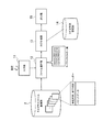
図1は、本実施の形態におけるログ生成装置の構成を示す機能ブロック図である。同図に示すログ生成装置は、ユーザ宅内の複数の通信機器が送受信するパケットを複数の通信機器の上流(例えば、ユーザ宅のローカルネットワークを外部のネットワークに接続するルータのユーザ宅側)でキャプチャしたパケットデータを記載したキャプチャファイルをキャプチャファイル蓄積部2から読み出し、パケットデータからログを生成する装置である。キャプチャファイル蓄積部2には、数カ月分のキャプチャデータが記載されたキャプチャファイルが蓄積される。キャプチャデータを記載したキャプチャファイルは、キャプチャファイルのサイズやキャプチャの期間に応じて複数に分割されてキャプチャファイル蓄積部2に蓄積される。キャプチャファイルには、キャプチャしたパケットデータがキャプチャ時刻とともに時系列順に記載される。また、キャプチャファイル内で一番最初のキャプチャデータのキャプチャ時刻を開始時刻、一番最後のキャプチャデータのキャプチャ時刻を終了時刻としたヘッダーを備える。
FIG. 1 is a functional block diagram illustrating a configuration of a log generation device according to the present embodiment. The log generation device shown in the figure captures packets transmitted and received by a plurality of communication devices in the user's home upstream of the plurality of communication devices (for example, the user's home side of a router that connects the local network of the user's home to an external network). This is a device that reads a capture file that describes the packet data from the capture
図1に示すログ生成装置は、入力部11、ファイル操作部12、ログ生成部13、ログ文字列蓄積部14、および出力部15を備える。ログ生成装置が備える各部は、演算処理装置、記憶装置等を備えたコンピュータにより構成して、各部の処理がプログラムによって実行されるものとしてもよい。このプログラムはログ生成装置が備える記憶装置に記憶されており、磁気ディスク、光ディスク、半導体メモリ等の記録媒体に記録することも、ネットワークを通して提供することも可能である。
The log generation device illustrated in FIG. 1 includes an
入力部11は、キャプチャファイルが蓄積されている格納場所の指定、生成するログに関する設定、およびログをファイルに書き出す場合の出力先を入力する。
The
キャプチャファイルが蓄積されている格納場所の指定は、例えば、キャプチャファイル蓄積部2がキャプチャファイルを蓄積しているフォルダを指定する。指定されたフォルダに存在するキャプチャファイル全てが処理対象となる。あるいは、キャプチャファイルを複数選択して処理対象のキャプチャファイルを指定してもよい。
The storage location where the capture file is stored is, for example, a folder where the capture
ファイル操作部12は、入力部11が入力したキャプチャファイルの格納場所からキャプチャファイルを時系列順に取得してキャプチャデータ解析装置が備えるメモリ上に読み込む。指定された格納場所に存在する全てのキャプチャファイルをメモリ上に一度に全部読み込むことはできないので、メモリ上に読み込んだキャプチャファイルをログ生成部13が処理した後は、メモリ上のデータを破棄して次のキャプチャファイルを読み込む。キャプチャファイルの時系列順は、キャプチャファイルの先頭に記述されたヘッダーの開始時刻、終了時刻を参照して判定する。あるいは、キャプチャファイルのファイル名が規則的に付けられる場合、例えばファイル名に通し番号が付与される場合、ファイル名に作成された日時を含む場合など、そのファイル名によりキャプチャファイルの時系列順を判定してもよい。キャプチャファイルの時系列順は、例えばキャプチャファイルのファイル名を時系列順に並べてファイル操作部12が保持しておくとよい。
The
ログ生成部13は、ファイル操作部12が読み込んだキャプチャファイルからパケットデータを順次取得して、パケットデータからパケットの種別、イベント、パラメータなどを抽出し、パケットの種別、イベントをキーにして出力する文字列をログ文字列蓄積部14から検索し、検索した文字列にパラメータを付与してログを生成する。パケットの種別としては、トランスポート層以下のPPP、ARP、TCP、UDPに加えて、アプリケーション層のDNS、SIP、ICMPv6、DHCPも区別する。イベントは、パケットデータ中のフラグやメッセージなどから判断する。イベントとしては、例えばPPP接続開始、ARP Request、SIPのINVITEメッセージなどがある。パラメータとしては、例えばIPアドレス、セッションID、SIPのCall−IDなどがある。
The
また、ログ生成部13は、パケットデータから直接生成できるログだけでなく、間接的に生成できるログも生成する。例えば、TCPのSYNパケットに対してはSYN/ACKパケットが返送されるが、SYNパケットを送信してから所定の時間以内に対応するSYN/ACKパケットを受信していない場合、つまりSYN/ACKパケットのパケットデータがキャプチャファイル中のSYNパケットのキャプチャ時刻から所定の時間までの間に記載されていない場合、その旨を示すログを生成する。
In addition, the
ログ文字列蓄積部14は、ログ生成部13が出力するログの雛形となる文字列、パケットの種別、イベント、および重要度を関連付けて蓄積する。重要度は、関連付けられた文字列が単なる情報の提供なのか警告であるのかを示す値である。
The log character
出力部15は、ログ生成部13が生成したログを出力する。出力方法としては、ログ生成装置に接続されたディスプレイに表示する方法や、入力部11で入力した出力先のファイルに書き出す方法がある。なお、出力するログの種類については入力部11を用いて設定できる。例えば、入力部11でログを出力するパケットの種別を選択するチェックボックスを表示し、出力部15は、チェックされたパケットの種別についてのみログを出力する。あるいは、重要度を選択したり、特定のサービスに関連するログを選択できるようにする。
The
次に、本実施の形態におけるログ生成装置の動作について説明する。 Next, the operation of the log generation device in this embodiment will be described.
図2は、本実施の形態におけるログ生成装置の処理の流れを示すフローチャートである。 FIG. 2 is a flowchart showing a processing flow of the log generation device according to the present embodiment.
まず、入力部11がキャプチャファイルの格納場所を入力する(ステップS11)。このとき、ログ生成の対象期間を示す抜き出し期間やオフセット時間を入力してもよい。抜き出し期間が指定された場合は、キャプチャファイルすべてからログを生成するのではなく、抜き出し期間内にキャプチャされたパケットデータからログを生成する。オフセット時間が指定された場合は、キャプチャファイルに記録されたパケットのキャプチャ時刻をオフセット時間で補正する。
First, the
続いて、ファイル操作部12がキャプチャファイルを時系列順に取得してメモリ上に読み込む(ステップS12)。
Subsequently, the
そして、ログ生成部13が読み込まれたキャプチャファイルに記載されたパケットデータを取得してログを生成する(ステップS13)。ログ生成処理の詳細については後述する。
Then, the
読み込んだキャプチャファイルの処理が終了すると、処理対象となるキャプチャファイルを全て処理したか否か判定し(ステップS14)、まだ処理していないキャプチャファイルが存在する場合は(ステップS14のNo)、ステップS12に戻り次のキャプチャファイルを読み込む。このときメモリ上に読み込まれているキャプチャファイルは処理し終えているので破棄する。 When processing of the read capture file is completed, it is determined whether or not all capture files to be processed have been processed (step S14). If there is a capture file that has not been processed yet (No in step S14), step Returning to S12, the next capture file is read. At this time, the capture file read in the memory has been processed and is discarded.
処理対象となるキャプチャファイルを全て処理した場合は(ステップS14のYes)、ログ生成部13が生成したログを出力部15が出力する(ステップS15)。
When all the capture files to be processed are processed (Yes in step S14), the
次に、ログ生成部13によるログ生成処理について説明する。
Next, log generation processing by the
ログ生成部13は、ファイル操作部12が読み込んだキャプチャファイルからパケットデータを取得し、パケットの種別を判定する。
The
また、ログ生成部13は、パケットデータ中のフラグやメッセージを取得してイベントを判定する。例えば、パケットの種別がTCPでSYNフラグがセットされている場合は、SYNパケットを送信するイベントであると判定する。別の例としては、パケットの種別がSIPでINVITEメッセージであればINVITEのイベントであると判定する。
In addition, the
そして、パケットの種別とイベントの組みをキーにログ文字列蓄積部14を検索して文字列を取得する。
Then, the log character
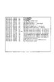
図3に、ログ文字列蓄積部14に蓄積されたデータの例を示す。同図に示すように、ログ文字列蓄積部14には、パケットの種別、イベント、重要度、および文字列が関連付けられて格納されている。重要度は、イベントの重要度を示しており、本実施の形態では、単なる通知を示すINFOあるいは警告を示すWARNを記載する。文字列には、パケットデータから取得するパラメータを付与する部分を有するものもある。例えば、図3のARP Requestのイベントに対応する文字列には、尋ねるIPアドレスを付与する部分(xxx.xxx.xxx.xxx)が存在する。ログ生成時には、この部分にパケットデータから取得したIPアドレスが付与される。
FIG. 3 shows an example of data stored in the log character
ログ生成部13は、必要ならばパラメータを文字列に付与し、キャプチャ時刻、パケットの種別、および文字列で構成されたログを出力部15へ渡す。図4に、出力部15によるログの出力例を示す。同図に示す出力例は、キャプチャ時刻、パケットの種別、文字列を表示している。ログの各行には、キャプチャファイル中の該当パケットデータへのリンクを張っておき、そのリンクを選択することで、対応するパケットデータの閲覧が可能となる。
If necessary, the
なお、応答の返信があると推定されるパケットデータについてはタイマを設定し、キャプチャ時刻にタイマを加えた時刻内に、対応する返信パケットデータがキャプチャファイルに存在しない場合は、応答無しのイベントをログ文字列蓄積部14から検索してログを生成する。このとき、ログとして出力する時刻はキャプチャ時刻にタイマを加えた値とし、文字列に付与するパラメータは元となるパケットデータから取得する。タイマの値は利用者が任意に設定できる。
Note that a timer is set for packet data that is estimated to have a response reply, and if there is no corresponding reply packet data in the capture file within the time that is added to the capture time, an event with no response is sent. A log is generated by searching from the log character
以上説明したように、本実施の形態によれば、複数の通信機器が送受信するパケットをキャプチャしたキャプチャデータを記載したキャプチャファイルからキャプチャデータを取得してパケットの種別とイベントを判別し、ログ文字列蓄積部14から対応する文字列を検索してログを生成することにより、複数の通信機器に関するログを所望の形式で一括して生成することができる。また、パケットのキャプチャ時刻を用いてログを生成するので、各通信機器の時刻がずれていた場合でもログの並び順が前後することがない。さらに、通信機器が保持するログが消去されていた場合でも、キャプチャファイル蓄積部2にパケットデータが存在すればログが生成できる。
As described above, according to the present embodiment, the capture data is acquired from the capture file describing the capture data obtained by capturing the packets transmitted / received by a plurality of communication devices, the packet type and event are determined, and the log character By searching for a corresponding character string from the
11…入力部
12…ファイル操作部
13…ログ生成部
14…ログ文字列蓄積部
15…出力部
2…キャプチャファイル蓄積部
DESCRIPTION OF
Claims (1)
キャプチャファイルを入力する入力手段と、
パケットデータに基づくイベントとログの雛形となる文字列とを関連付けて蓄積した蓄積手段と、
前記キャプチャファイルからパケットデータを取得し、当該パケットデータに基づくイベントをキーにして前記蓄積手段から対応する前記文字列を読み出してログを生成する生成手段と、
前記ログを出力する出力手段と、を有し、
前記生成手段は、取得した前記パケットデータに対して応答される返信パケットデータが存在すると推定されるときに、前記キャプチャファイルに前記返信パケットデータが存在しない場合は、その旨のログを生成することを特徴とするログ生成装置。 A log generation device that generates a log from a capture file that describes packet data obtained by capturing packets transmitted and received by a plurality of communication devices,
An input means for inputting a capture file;
An accumulation means for accumulating an event based on packet data and a character string as a log template in association with each other,
Generating means for acquiring packet data from the capture file, reading the corresponding character string from the storage means using an event based on the packet data as a key, and generating a log;
Output means for outputting the log ,
The generation means generates a log to that effect when there is no reply packet data in the capture file when it is estimated that there is reply packet data to be responded to the acquired packet data. A log generation device characterized by the above.
Priority Applications (1)
| Application Number | Priority Date | Filing Date | Title |
|---|---|---|---|
| JP2012270220A JP5991908B2 (en) | 2012-12-11 | 2012-12-11 | Log generator |
Applications Claiming Priority (1)
| Application Number | Priority Date | Filing Date | Title |
|---|---|---|---|
| JP2012270220A JP5991908B2 (en) | 2012-12-11 | 2012-12-11 | Log generator |
Publications (2)
| Publication Number | Publication Date |
|---|---|
| JP2014115871A JP2014115871A (en) | 2014-06-26 |
| JP5991908B2 true JP5991908B2 (en) | 2016-09-14 |
Family
ID=51171790
Family Applications (1)
| Application Number | Title | Priority Date | Filing Date |
|---|---|---|---|
| JP2012270220A Active JP5991908B2 (en) | 2012-12-11 | 2012-12-11 | Log generator |
Country Status (1)
| Country | Link |
|---|---|
| JP (1) | JP5991908B2 (en) |
Families Citing this family (1)
| Publication number | Priority date | Publication date | Assignee | Title |
|---|---|---|---|---|
| WO2022123677A1 (en) * | 2020-12-09 | 2022-06-16 | 日本電信電話株式会社 | Packet capture device, time stamp correction method, packet capture method, and packet capture program |
Family Cites Families (4)
| Publication number | Priority date | Publication date | Assignee | Title |
|---|---|---|---|---|
| JPH07271696A (en) * | 1994-03-30 | 1995-10-20 | Hitachi Software Eng Co Ltd | Analytic display method for protocol data |
| JP3343054B2 (en) * | 1997-07-01 | 2002-11-11 | ケイディーディーアイ株式会社 | Internet compatible link monitor method |
| JP4699893B2 (en) * | 2005-12-19 | 2011-06-15 | 三菱スペース・ソフトウエア株式会社 | Packet analysis system, packet analysis program, packet analysis method, and packet acquisition device |
| JP5271247B2 (en) * | 2009-12-15 | 2013-08-21 | 日本電信電話株式会社 | Communication quality data monitoring measurement apparatus and method and program |
-
2012
- 2012-12-11 JP JP2012270220A patent/JP5991908B2/en active Active
Also Published As
| Publication number | Publication date |
|---|---|
| JP2014115871A (en) | 2014-06-26 |
Similar Documents
| Publication | Publication Date | Title |
|---|---|---|
| JP4479459B2 (en) | Packet analysis system | |
| CN106878074B (en) | Flow filtering method and device | |
| CN109361573B (en) | Flow log analysis method, system and computer readable storage medium | |
| CN106250290A (en) | The analysis method and device of abnormal information | |
| JP2016177594A (en) | COMMUNICATION TERMINAL DEVICE, COMMUNICATION SYSTEM, COMMUNICATION METHOD, AND PROGRAM | |
| JP6733147B2 (en) | Communication system, relay method, and relay program | |
| CN111277569B (en) | Network message decoding method and device and electronic equipment | |
| JP5768448B2 (en) | Log management system, log analysis device, log analysis method, and log analysis program | |
| JP5991908B2 (en) | Log generator | |
| CN111586092A (en) | Full link monitoring method, system and CAT client | |
| JP2006190033A (en) | Information processing system and communication reproduction processing method | |
| JP2012156853A (en) | Communication network test data generation device and communication network test data generation method | |
| JP6157189B2 (en) | Identification device, identification method, and identification program | |
| JP2014225179A (en) | Log acquisition device, log acquisition method, and log acquisition program | |
| JP5287898B2 (en) | Flow monitoring apparatus, flow monitoring method and program | |
| JP2016075974A (en) | COMMUNICATION TERMINAL DEVICE, COMMUNICATION SYSTEM, COMMUNICATION METHOD, AND PROGRAM | |
| JP5686001B2 (en) | Information processing apparatus, message isolation method, and message isolation program | |
| JP5870078B2 (en) | Capture data analyzer | |
| JP5820749B2 (en) | Identification device, identification method, and identification program | |
| JP2019082941A (en) | Log collection system and program | |
| JP2014116827A (en) | Capture data analysis device | |
| JP2008305289A (en) | How to find applications | |
| KR20100133646A (en) | How to create an application signature | |
| JP2013150195A (en) | Communication packet analyzer | |
| JP6023738B2 (en) | Transmission packet analysis system, transmission packet analysis device, and transmission packet analysis program |
Legal Events
| Date | Code | Title | Description |
|---|---|---|---|
| A621 | Written request for application examination |
Free format text: JAPANESE INTERMEDIATE CODE: A621 Effective date: 20150319 |
|
| A977 | Report on retrieval |
Free format text: JAPANESE INTERMEDIATE CODE: A971007 Effective date: 20151216 |
|
| A131 | Notification of reasons for refusal |
Free format text: JAPANESE INTERMEDIATE CODE: A131 Effective date: 20160126 |
|
| A521 | Request for written amendment filed |
Free format text: JAPANESE INTERMEDIATE CODE: A523 Effective date: 20160316 |
|
| TRDD | Decision of grant or rejection written | ||
| A01 | Written decision to grant a patent or to grant a registration (utility model) |
Free format text: JAPANESE INTERMEDIATE CODE: A01 Effective date: 20160809 |
|
| A61 | First payment of annual fees (during grant procedure) |
Free format text: JAPANESE INTERMEDIATE CODE: A61 Effective date: 20160816 |
|
| R150 | Certificate of patent or registration of utility model |
Ref document number: 5991908 Country of ref document: JP Free format text: JAPANESE INTERMEDIATE CODE: R150 |
|
| R250 | Receipt of annual fees |
Free format text: JAPANESE INTERMEDIATE CODE: R250 |
|
| R250 | Receipt of annual fees |
Free format text: JAPANESE INTERMEDIATE CODE: R250 |
|
| R250 | Receipt of annual fees |
Free format text: JAPANESE INTERMEDIATE CODE: R250 |
|
| R250 | Receipt of annual fees |
Free format text: JAPANESE INTERMEDIATE CODE: R250 |
|
| R250 | Receipt of annual fees |
Free format text: JAPANESE INTERMEDIATE CODE: R250 |
|
| R250 | Receipt of annual fees |
Free format text: JAPANESE INTERMEDIATE CODE: R250 |
|
| R250 | Receipt of annual fees |
Free format text: JAPANESE INTERMEDIATE CODE: R250 |
|
| S533 | Written request for registration of change of name |
Free format text: JAPANESE INTERMEDIATE CODE: R313533 |
|
| R350 | Written notification of registration of transfer |
Free format text: JAPANESE INTERMEDIATE CODE: R350 |