JP5990480B2 - Manufacturing method of resin composite structure - Google Patents
Manufacturing method of resin composite structure Download PDFInfo
- Publication number
- JP5990480B2 JP5990480B2 JP2013048599A JP2013048599A JP5990480B2 JP 5990480 B2 JP5990480 B2 JP 5990480B2 JP 2013048599 A JP2013048599 A JP 2013048599A JP 2013048599 A JP2013048599 A JP 2013048599A JP 5990480 B2 JP5990480 B2 JP 5990480B2
- Authority
- JP
- Japan
- Prior art keywords
- resin composite
- composite material
- overlapping
- manufacturing
- resin
- Prior art date
- Legal status (The legal status is an assumption and is not a legal conclusion. Google has not performed a legal analysis and makes no representation as to the accuracy of the status listed.)
- Expired - Fee Related
Links
Images


Classifications
-
- B—PERFORMING OPERATIONS; TRANSPORTING
- B29—WORKING OF PLASTICS; WORKING OF SUBSTANCES IN A PLASTIC STATE IN GENERAL
- B29C—SHAPING OR JOINING OF PLASTICS; SHAPING OF MATERIAL IN A PLASTIC STATE, NOT OTHERWISE PROVIDED FOR; AFTER-TREATMENT OF THE SHAPED PRODUCTS, e.g. REPAIRING
- B29C65/00—Joining or sealing of preformed parts, e.g. welding of plastics materials; Apparatus therefor
- B29C65/02—Joining or sealing of preformed parts, e.g. welding of plastics materials; Apparatus therefor by heating, with or without pressure
- B29C65/18—Joining or sealing of preformed parts, e.g. welding of plastics materials; Apparatus therefor by heating, with or without pressure using heated tools
- B29C65/20—Joining or sealing of preformed parts, e.g. welding of plastics materials; Apparatus therefor by heating, with or without pressure using heated tools with direct contact, e.g. using "mirror"
-
- B—PERFORMING OPERATIONS; TRANSPORTING
- B32—LAYERED PRODUCTS
- B32B—LAYERED PRODUCTS, i.e. PRODUCTS BUILT-UP OF STRATA OF FLAT OR NON-FLAT, e.g. CELLULAR OR HONEYCOMB, FORM
- B32B3/00—Layered products comprising a layer with external or internal discontinuities or unevennesses, or a layer of non-planar form; Layered products having particular features of form
- B32B3/02—Layered products comprising a layer with external or internal discontinuities or unevennesses, or a layer of non-planar form; Layered products having particular features of form characterised by features of form at particular places, e.g. in edge regions
- B32B3/06—Layered products comprising a layer with external or internal discontinuities or unevennesses, or a layer of non-planar form; Layered products having particular features of form characterised by features of form at particular places, e.g. in edge regions for securing layers together; for attaching the product to another member, e.g. to a support, or to another product, e.g. groove/tongue, interlocking
-
- B—PERFORMING OPERATIONS; TRANSPORTING
- B29—WORKING OF PLASTICS; WORKING OF SUBSTANCES IN A PLASTIC STATE IN GENERAL
- B29C—SHAPING OR JOINING OF PLASTICS; SHAPING OF MATERIAL IN A PLASTIC STATE, NOT OTHERWISE PROVIDED FOR; AFTER-TREATMENT OF THE SHAPED PRODUCTS, e.g. REPAIRING
- B29C65/00—Joining or sealing of preformed parts, e.g. welding of plastics materials; Apparatus therefor
- B29C65/02—Joining or sealing of preformed parts, e.g. welding of plastics materials; Apparatus therefor by heating, with or without pressure
- B29C65/022—Particular heating or welding methods not otherwise provided for
-
- B—PERFORMING OPERATIONS; TRANSPORTING
- B29—WORKING OF PLASTICS; WORKING OF SUBSTANCES IN A PLASTIC STATE IN GENERAL
- B29C—SHAPING OR JOINING OF PLASTICS; SHAPING OF MATERIAL IN A PLASTIC STATE, NOT OTHERWISE PROVIDED FOR; AFTER-TREATMENT OF THE SHAPED PRODUCTS, e.g. REPAIRING
- B29C65/00—Joining or sealing of preformed parts, e.g. welding of plastics materials; Apparatus therefor
- B29C65/02—Joining or sealing of preformed parts, e.g. welding of plastics materials; Apparatus therefor by heating, with or without pressure
- B29C65/18—Joining or sealing of preformed parts, e.g. welding of plastics materials; Apparatus therefor by heating, with or without pressure using heated tools
- B29C65/24—Joining or sealing of preformed parts, e.g. welding of plastics materials; Apparatus therefor by heating, with or without pressure using heated tools characterised by the means for heating the tool
- B29C65/30—Electrical means
- B29C65/305—Electrical means involving the use of cartridge heaters
-
- B—PERFORMING OPERATIONS; TRANSPORTING
- B29—WORKING OF PLASTICS; WORKING OF SUBSTANCES IN A PLASTIC STATE IN GENERAL
- B29C—SHAPING OR JOINING OF PLASTICS; SHAPING OF MATERIAL IN A PLASTIC STATE, NOT OTHERWISE PROVIDED FOR; AFTER-TREATMENT OF THE SHAPED PRODUCTS, e.g. REPAIRING
- B29C65/00—Joining or sealing of preformed parts, e.g. welding of plastics materials; Apparatus therefor
- B29C65/72—Joining or sealing of preformed parts, e.g. welding of plastics materials; Apparatus therefor by combined operations or combined techniques, e.g. welding and stitching
-
- B—PERFORMING OPERATIONS; TRANSPORTING
- B29—WORKING OF PLASTICS; WORKING OF SUBSTANCES IN A PLASTIC STATE IN GENERAL
- B29C—SHAPING OR JOINING OF PLASTICS; SHAPING OF MATERIAL IN A PLASTIC STATE, NOT OTHERWISE PROVIDED FOR; AFTER-TREATMENT OF THE SHAPED PRODUCTS, e.g. REPAIRING
- B29C65/00—Joining or sealing of preformed parts, e.g. welding of plastics materials; Apparatus therefor
- B29C65/78—Means for handling the parts to be joined, e.g. for making containers or hollow articles, e.g. means for handling sheets, plates, web-like materials, tubular articles, hollow articles or elements to be joined therewith; Means for discharging the joined articles from the joining apparatus
- B29C65/7841—Holding or clamping means for handling purposes
-
- B—PERFORMING OPERATIONS; TRANSPORTING
- B29—WORKING OF PLASTICS; WORKING OF SUBSTANCES IN A PLASTIC STATE IN GENERAL
- B29C—SHAPING OR JOINING OF PLASTICS; SHAPING OF MATERIAL IN A PLASTIC STATE, NOT OTHERWISE PROVIDED FOR; AFTER-TREATMENT OF THE SHAPED PRODUCTS, e.g. REPAIRING
- B29C66/00—General aspects of processes or apparatus for joining preformed parts
- B29C66/01—General aspects dealing with the joint area or with the area to be joined
- B29C66/05—Particular design of joint configurations
- B29C66/10—Particular design of joint configurations particular design of the joint cross-sections
- B29C66/11—Joint cross-sections comprising a single joint-segment, i.e. one of the parts to be joined comprising a single joint-segment in the joint cross-section
- B29C66/112—Single lapped joints
- B29C66/1122—Single lap to lap joints, i.e. overlap joints
-
- B—PERFORMING OPERATIONS; TRANSPORTING
- B29—WORKING OF PLASTICS; WORKING OF SUBSTANCES IN A PLASTIC STATE IN GENERAL
- B29C—SHAPING OR JOINING OF PLASTICS; SHAPING OF MATERIAL IN A PLASTIC STATE, NOT OTHERWISE PROVIDED FOR; AFTER-TREATMENT OF THE SHAPED PRODUCTS, e.g. REPAIRING
- B29C66/00—General aspects of processes or apparatus for joining preformed parts
- B29C66/01—General aspects dealing with the joint area or with the area to be joined
- B29C66/05—Particular design of joint configurations
- B29C66/20—Particular design of joint configurations particular design of the joint lines, e.g. of the weld lines
- B29C66/22—Particular design of joint configurations particular design of the joint lines, e.g. of the weld lines said joint lines being in the form of recurring patterns
- B29C66/221—Particular design of joint configurations particular design of the joint lines, e.g. of the weld lines said joint lines being in the form of recurring patterns being in the form of a sinusoidal wave
-
- B—PERFORMING OPERATIONS; TRANSPORTING
- B29—WORKING OF PLASTICS; WORKING OF SUBSTANCES IN A PLASTIC STATE IN GENERAL
- B29C—SHAPING OR JOINING OF PLASTICS; SHAPING OF MATERIAL IN A PLASTIC STATE, NOT OTHERWISE PROVIDED FOR; AFTER-TREATMENT OF THE SHAPED PRODUCTS, e.g. REPAIRING
- B29C66/00—General aspects of processes or apparatus for joining preformed parts
- B29C66/01—General aspects dealing with the joint area or with the area to be joined
- B29C66/05—Particular design of joint configurations
- B29C66/20—Particular design of joint configurations particular design of the joint lines, e.g. of the weld lines
- B29C66/22—Particular design of joint configurations particular design of the joint lines, e.g. of the weld lines said joint lines being in the form of recurring patterns
- B29C66/223—Particular design of joint configurations particular design of the joint lines, e.g. of the weld lines said joint lines being in the form of recurring patterns being in the form of a triangle wave or of a sawtooth wave, e.g. zigzagged
-
- B—PERFORMING OPERATIONS; TRANSPORTING
- B29—WORKING OF PLASTICS; WORKING OF SUBSTANCES IN A PLASTIC STATE IN GENERAL
- B29C—SHAPING OR JOINING OF PLASTICS; SHAPING OF MATERIAL IN A PLASTIC STATE, NOT OTHERWISE PROVIDED FOR; AFTER-TREATMENT OF THE SHAPED PRODUCTS, e.g. REPAIRING
- B29C66/00—General aspects of processes or apparatus for joining preformed parts
- B29C66/01—General aspects dealing with the joint area or with the area to be joined
- B29C66/341—Measures for intermixing the material of the joint interlayer
-
- B—PERFORMING OPERATIONS; TRANSPORTING
- B29—WORKING OF PLASTICS; WORKING OF SUBSTANCES IN A PLASTIC STATE IN GENERAL
- B29C—SHAPING OR JOINING OF PLASTICS; SHAPING OF MATERIAL IN A PLASTIC STATE, NOT OTHERWISE PROVIDED FOR; AFTER-TREATMENT OF THE SHAPED PRODUCTS, e.g. REPAIRING
- B29C66/00—General aspects of processes or apparatus for joining preformed parts
- B29C66/40—General aspects of joining substantially flat articles, e.g. plates, sheets or web-like materials; Making flat seams in tubular or hollow articles; Joining single elements to substantially flat surfaces
- B29C66/41—Joining substantially flat articles ; Making flat seams in tubular or hollow articles
- B29C66/43—Joining a relatively small portion of the surface of said articles
-
- B—PERFORMING OPERATIONS; TRANSPORTING
- B29—WORKING OF PLASTICS; WORKING OF SUBSTANCES IN A PLASTIC STATE IN GENERAL
- B29C—SHAPING OR JOINING OF PLASTICS; SHAPING OF MATERIAL IN A PLASTIC STATE, NOT OTHERWISE PROVIDED FOR; AFTER-TREATMENT OF THE SHAPED PRODUCTS, e.g. REPAIRING
- B29C66/00—General aspects of processes or apparatus for joining preformed parts
- B29C66/50—General aspects of joining tubular articles; General aspects of joining long products, i.e. bars or profiled elements; General aspects of joining single elements to tubular articles, hollow articles or bars; General aspects of joining several hollow-preforms to form hollow or tubular articles
- B29C66/51—Joining tubular articles, profiled elements or bars; Joining single elements to tubular articles, hollow articles or bars; Joining several hollow-preforms to form hollow or tubular articles
- B29C66/52—Joining tubular articles, bars or profiled elements
- B29C66/524—Joining profiled elements
- B29C66/5241—Joining profiled elements for forming coaxial connections, i.e. the profiled elements to be joined forming a zero angle relative to each other
-
- B—PERFORMING OPERATIONS; TRANSPORTING
- B29—WORKING OF PLASTICS; WORKING OF SUBSTANCES IN A PLASTIC STATE IN GENERAL
- B29C—SHAPING OR JOINING OF PLASTICS; SHAPING OF MATERIAL IN A PLASTIC STATE, NOT OTHERWISE PROVIDED FOR; AFTER-TREATMENT OF THE SHAPED PRODUCTS, e.g. REPAIRING
- B29C66/00—General aspects of processes or apparatus for joining preformed parts
- B29C66/50—General aspects of joining tubular articles; General aspects of joining long products, i.e. bars or profiled elements; General aspects of joining single elements to tubular articles, hollow articles or bars; General aspects of joining several hollow-preforms to form hollow or tubular articles
- B29C66/51—Joining tubular articles, profiled elements or bars; Joining single elements to tubular articles, hollow articles or bars; Joining several hollow-preforms to form hollow or tubular articles
- B29C66/54—Joining several hollow-preforms, e.g. half-shells, to form hollow articles, e.g. for making balls, containers; Joining several hollow-preforms, e.g. half-cylinders, to form tubular articles
- B29C66/543—Joining several hollow-preforms, e.g. half-shells, to form hollow articles, e.g. for making balls, containers; Joining several hollow-preforms, e.g. half-cylinders, to form tubular articles joining more than two hollow-preforms to form said hollow articles
-
- B—PERFORMING OPERATIONS; TRANSPORTING
- B29—WORKING OF PLASTICS; WORKING OF SUBSTANCES IN A PLASTIC STATE IN GENERAL
- B29C—SHAPING OR JOINING OF PLASTICS; SHAPING OF MATERIAL IN A PLASTIC STATE, NOT OTHERWISE PROVIDED FOR; AFTER-TREATMENT OF THE SHAPED PRODUCTS, e.g. REPAIRING
- B29C66/00—General aspects of processes or apparatus for joining preformed parts
- B29C66/50—General aspects of joining tubular articles; General aspects of joining long products, i.e. bars or profiled elements; General aspects of joining single elements to tubular articles, hollow articles or bars; General aspects of joining several hollow-preforms to form hollow or tubular articles
- B29C66/63—Internally supporting the article during joining
-
- B—PERFORMING OPERATIONS; TRANSPORTING
- B29—WORKING OF PLASTICS; WORKING OF SUBSTANCES IN A PLASTIC STATE IN GENERAL
- B29C—SHAPING OR JOINING OF PLASTICS; SHAPING OF MATERIAL IN A PLASTIC STATE, NOT OTHERWISE PROVIDED FOR; AFTER-TREATMENT OF THE SHAPED PRODUCTS, e.g. REPAIRING
- B29C66/00—General aspects of processes or apparatus for joining preformed parts
- B29C66/70—General aspects of processes or apparatus for joining preformed parts characterised by the composition, physical properties or the structure of the material of the parts to be joined; Joining with non-plastics material
- B29C66/72—General aspects of processes or apparatus for joining preformed parts characterised by the composition, physical properties or the structure of the material of the parts to be joined; Joining with non-plastics material characterised by the structure of the material of the parts to be joined
- B29C66/721—Fibre-reinforced materials
- B29C66/7214—Fibre-reinforced materials characterised by the length of the fibres
- B29C66/72143—Fibres of discontinuous lengths
-
- B—PERFORMING OPERATIONS; TRANSPORTING
- B29—WORKING OF PLASTICS; WORKING OF SUBSTANCES IN A PLASTIC STATE IN GENERAL
- B29C—SHAPING OR JOINING OF PLASTICS; SHAPING OF MATERIAL IN A PLASTIC STATE, NOT OTHERWISE PROVIDED FOR; AFTER-TREATMENT OF THE SHAPED PRODUCTS, e.g. REPAIRING
- B29C66/00—General aspects of processes or apparatus for joining preformed parts
- B29C66/70—General aspects of processes or apparatus for joining preformed parts characterised by the composition, physical properties or the structure of the material of the parts to be joined; Joining with non-plastics material
- B29C66/73—General aspects of processes or apparatus for joining preformed parts characterised by the composition, physical properties or the structure of the material of the parts to be joined; Joining with non-plastics material characterised by the intensive physical properties of the material of the parts to be joined, by the optical properties of the material of the parts to be joined, by the extensive physical properties of the parts to be joined, by the state of the material of the parts to be joined or by the material of the parts to be joined being a thermoplastic or a thermoset
- B29C66/739—General aspects of processes or apparatus for joining preformed parts characterised by the composition, physical properties or the structure of the material of the parts to be joined; Joining with non-plastics material characterised by the intensive physical properties of the material of the parts to be joined, by the optical properties of the material of the parts to be joined, by the extensive physical properties of the parts to be joined, by the state of the material of the parts to be joined or by the material of the parts to be joined being a thermoplastic or a thermoset characterised by the material of the parts to be joined being a thermoplastic or a thermoset
- B29C66/7392—General aspects of processes or apparatus for joining preformed parts characterised by the composition, physical properties or the structure of the material of the parts to be joined; Joining with non-plastics material characterised by the intensive physical properties of the material of the parts to be joined, by the optical properties of the material of the parts to be joined, by the extensive physical properties of the parts to be joined, by the state of the material of the parts to be joined or by the material of the parts to be joined being a thermoplastic or a thermoset characterised by the material of the parts to be joined being a thermoplastic or a thermoset characterised by the material of at least one of the parts being a thermoplastic
- B29C66/73921—General aspects of processes or apparatus for joining preformed parts characterised by the composition, physical properties or the structure of the material of the parts to be joined; Joining with non-plastics material characterised by the intensive physical properties of the material of the parts to be joined, by the optical properties of the material of the parts to be joined, by the extensive physical properties of the parts to be joined, by the state of the material of the parts to be joined or by the material of the parts to be joined being a thermoplastic or a thermoset characterised by the material of the parts to be joined being a thermoplastic or a thermoset characterised by the material of at least one of the parts being a thermoplastic characterised by the materials of both parts being thermoplastics
-
- B—PERFORMING OPERATIONS; TRANSPORTING
- B29—WORKING OF PLASTICS; WORKING OF SUBSTANCES IN A PLASTIC STATE IN GENERAL
- B29C—SHAPING OR JOINING OF PLASTICS; SHAPING OF MATERIAL IN A PLASTIC STATE, NOT OTHERWISE PROVIDED FOR; AFTER-TREATMENT OF THE SHAPED PRODUCTS, e.g. REPAIRING
- B29C66/00—General aspects of processes or apparatus for joining preformed parts
- B29C66/80—General aspects of machine operations or constructions and parts thereof
- B29C66/81—General aspects of the pressing elements, i.e. the elements applying pressure on the parts to be joined in the area to be joined, e.g. the welding jaws or clamps
- B29C66/814—General aspects of the pressing elements, i.e. the elements applying pressure on the parts to be joined in the area to be joined, e.g. the welding jaws or clamps characterised by the design of the pressing elements, e.g. of the welding jaws or clamps
- B29C66/8141—General aspects of the pressing elements, i.e. the elements applying pressure on the parts to be joined in the area to be joined, e.g. the welding jaws or clamps characterised by the design of the pressing elements, e.g. of the welding jaws or clamps characterised by the surface geometry of the part of the pressing elements, e.g. welding jaws or clamps, coming into contact with the parts to be joined
- B29C66/81427—General aspects of the pressing elements, i.e. the elements applying pressure on the parts to be joined in the area to be joined, e.g. the welding jaws or clamps characterised by the design of the pressing elements, e.g. of the welding jaws or clamps characterised by the surface geometry of the part of the pressing elements, e.g. welding jaws or clamps, coming into contact with the parts to be joined comprising a single ridge, e.g. for making a weakening line; comprising a single tooth
-
- B—PERFORMING OPERATIONS; TRANSPORTING
- B29—WORKING OF PLASTICS; WORKING OF SUBSTANCES IN A PLASTIC STATE IN GENERAL
- B29C—SHAPING OR JOINING OF PLASTICS; SHAPING OF MATERIAL IN A PLASTIC STATE, NOT OTHERWISE PROVIDED FOR; AFTER-TREATMENT OF THE SHAPED PRODUCTS, e.g. REPAIRING
- B29C66/00—General aspects of processes or apparatus for joining preformed parts
- B29C66/80—General aspects of machine operations or constructions and parts thereof
- B29C66/81—General aspects of the pressing elements, i.e. the elements applying pressure on the parts to be joined in the area to be joined, e.g. the welding jaws or clamps
- B29C66/814—General aspects of the pressing elements, i.e. the elements applying pressure on the parts to be joined in the area to be joined, e.g. the welding jaws or clamps characterised by the design of the pressing elements, e.g. of the welding jaws or clamps
- B29C66/8141—General aspects of the pressing elements, i.e. the elements applying pressure on the parts to be joined in the area to be joined, e.g. the welding jaws or clamps characterised by the design of the pressing elements, e.g. of the welding jaws or clamps characterised by the surface geometry of the part of the pressing elements, e.g. welding jaws or clamps, coming into contact with the parts to be joined
- B29C66/81431—General aspects of the pressing elements, i.e. the elements applying pressure on the parts to be joined in the area to be joined, e.g. the welding jaws or clamps characterised by the design of the pressing elements, e.g. of the welding jaws or clamps characterised by the surface geometry of the part of the pressing elements, e.g. welding jaws or clamps, coming into contact with the parts to be joined comprising a single cavity, e.g. a groove
-
- B—PERFORMING OPERATIONS; TRANSPORTING
- B29—WORKING OF PLASTICS; WORKING OF SUBSTANCES IN A PLASTIC STATE IN GENERAL
- B29C—SHAPING OR JOINING OF PLASTICS; SHAPING OF MATERIAL IN A PLASTIC STATE, NOT OTHERWISE PROVIDED FOR; AFTER-TREATMENT OF THE SHAPED PRODUCTS, e.g. REPAIRING
- B29C66/00—General aspects of processes or apparatus for joining preformed parts
- B29C66/80—General aspects of machine operations or constructions and parts thereof
- B29C66/83—General aspects of machine operations or constructions and parts thereof characterised by the movement of the joining or pressing tools
- B29C66/832—Reciprocating joining or pressing tools
- B29C66/8322—Joining or pressing tools reciprocating along one axis
-
- B—PERFORMING OPERATIONS; TRANSPORTING
- B29—WORKING OF PLASTICS; WORKING OF SUBSTANCES IN A PLASTIC STATE IN GENERAL
- B29C—SHAPING OR JOINING OF PLASTICS; SHAPING OF MATERIAL IN A PLASTIC STATE, NOT OTHERWISE PROVIDED FOR; AFTER-TREATMENT OF THE SHAPED PRODUCTS, e.g. REPAIRING
- B29C65/00—Joining or sealing of preformed parts, e.g. welding of plastics materials; Apparatus therefor
- B29C65/48—Joining or sealing of preformed parts, e.g. welding of plastics materials; Apparatus therefor using adhesives, i.e. using supplementary joining material; solvent bonding
- B29C65/4805—Joining or sealing of preformed parts, e.g. welding of plastics materials; Apparatus therefor using adhesives, i.e. using supplementary joining material; solvent bonding characterised by the type of adhesives
- B29C65/481—Non-reactive adhesives, e.g. physically hardening adhesives
- B29C65/4815—Hot melt adhesives, e.g. thermoplastic adhesives
-
- B—PERFORMING OPERATIONS; TRANSPORTING
- B29—WORKING OF PLASTICS; WORKING OF SUBSTANCES IN A PLASTIC STATE IN GENERAL
- B29C—SHAPING OR JOINING OF PLASTICS; SHAPING OF MATERIAL IN A PLASTIC STATE, NOT OTHERWISE PROVIDED FOR; AFTER-TREATMENT OF THE SHAPED PRODUCTS, e.g. REPAIRING
- B29C65/00—Joining or sealing of preformed parts, e.g. welding of plastics materials; Apparatus therefor
- B29C65/48—Joining or sealing of preformed parts, e.g. welding of plastics materials; Apparatus therefor using adhesives, i.e. using supplementary joining material; solvent bonding
- B29C65/50—Joining or sealing of preformed parts, e.g. welding of plastics materials; Apparatus therefor using adhesives, i.e. using supplementary joining material; solvent bonding using adhesive tape, e.g. thermoplastic tape; using threads or the like
- B29C65/5007—Joining or sealing of preformed parts, e.g. welding of plastics materials; Apparatus therefor using adhesives, i.e. using supplementary joining material; solvent bonding using adhesive tape, e.g. thermoplastic tape; using threads or the like characterised by the structure of said adhesive tape, threads or the like
- B29C65/5014—Joining or sealing of preformed parts, e.g. welding of plastics materials; Apparatus therefor using adhesives, i.e. using supplementary joining material; solvent bonding using adhesive tape, e.g. thermoplastic tape; using threads or the like characterised by the structure of said adhesive tape, threads or the like being fibre-reinforced
-
- B—PERFORMING OPERATIONS; TRANSPORTING
- B29—WORKING OF PLASTICS; WORKING OF SUBSTANCES IN A PLASTIC STATE IN GENERAL
- B29C—SHAPING OR JOINING OF PLASTICS; SHAPING OF MATERIAL IN A PLASTIC STATE, NOT OTHERWISE PROVIDED FOR; AFTER-TREATMENT OF THE SHAPED PRODUCTS, e.g. REPAIRING
- B29C65/00—Joining or sealing of preformed parts, e.g. welding of plastics materials; Apparatus therefor
- B29C65/48—Joining or sealing of preformed parts, e.g. welding of plastics materials; Apparatus therefor using adhesives, i.e. using supplementary joining material; solvent bonding
- B29C65/50—Joining or sealing of preformed parts, e.g. welding of plastics materials; Apparatus therefor using adhesives, i.e. using supplementary joining material; solvent bonding using adhesive tape, e.g. thermoplastic tape; using threads or the like
- B29C65/5042—Joining or sealing of preformed parts, e.g. welding of plastics materials; Apparatus therefor using adhesives, i.e. using supplementary joining material; solvent bonding using adhesive tape, e.g. thermoplastic tape; using threads or the like covering both elements to be joined
-
- B—PERFORMING OPERATIONS; TRANSPORTING
- B29—WORKING OF PLASTICS; WORKING OF SUBSTANCES IN A PLASTIC STATE IN GENERAL
- B29C—SHAPING OR JOINING OF PLASTICS; SHAPING OF MATERIAL IN A PLASTIC STATE, NOT OTHERWISE PROVIDED FOR; AFTER-TREATMENT OF THE SHAPED PRODUCTS, e.g. REPAIRING
- B29C65/00—Joining or sealing of preformed parts, e.g. welding of plastics materials; Apparatus therefor
- B29C65/48—Joining or sealing of preformed parts, e.g. welding of plastics materials; Apparatus therefor using adhesives, i.e. using supplementary joining material; solvent bonding
- B29C65/50—Joining or sealing of preformed parts, e.g. welding of plastics materials; Apparatus therefor using adhesives, i.e. using supplementary joining material; solvent bonding using adhesive tape, e.g. thermoplastic tape; using threads or the like
- B29C65/5064—Joining or sealing of preformed parts, e.g. welding of plastics materials; Apparatus therefor using adhesives, i.e. using supplementary joining material; solvent bonding using adhesive tape, e.g. thermoplastic tape; using threads or the like of particular form, e.g. being C-shaped, T-shaped
- B29C65/5071—Joining or sealing of preformed parts, e.g. welding of plastics materials; Apparatus therefor using adhesives, i.e. using supplementary joining material; solvent bonding using adhesive tape, e.g. thermoplastic tape; using threads or the like of particular form, e.g. being C-shaped, T-shaped and being composed by one single element
-
- B—PERFORMING OPERATIONS; TRANSPORTING
- B29—WORKING OF PLASTICS; WORKING OF SUBSTANCES IN A PLASTIC STATE IN GENERAL
- B29C—SHAPING OR JOINING OF PLASTICS; SHAPING OF MATERIAL IN A PLASTIC STATE, NOT OTHERWISE PROVIDED FOR; AFTER-TREATMENT OF THE SHAPED PRODUCTS, e.g. REPAIRING
- B29C65/00—Joining or sealing of preformed parts, e.g. welding of plastics materials; Apparatus therefor
- B29C65/48—Joining or sealing of preformed parts, e.g. welding of plastics materials; Apparatus therefor using adhesives, i.e. using supplementary joining material; solvent bonding
- B29C65/50—Joining or sealing of preformed parts, e.g. welding of plastics materials; Apparatus therefor using adhesives, i.e. using supplementary joining material; solvent bonding using adhesive tape, e.g. thermoplastic tape; using threads or the like
- B29C65/5064—Joining or sealing of preformed parts, e.g. welding of plastics materials; Apparatus therefor using adhesives, i.e. using supplementary joining material; solvent bonding using adhesive tape, e.g. thermoplastic tape; using threads or the like of particular form, e.g. being C-shaped, T-shaped
- B29C65/5078—Joining or sealing of preformed parts, e.g. welding of plastics materials; Apparatus therefor using adhesives, i.e. using supplementary joining material; solvent bonding using adhesive tape, e.g. thermoplastic tape; using threads or the like of particular form, e.g. being C-shaped, T-shaped and being composed by several elements
-
- B—PERFORMING OPERATIONS; TRANSPORTING
- B29—WORKING OF PLASTICS; WORKING OF SUBSTANCES IN A PLASTIC STATE IN GENERAL
- B29C—SHAPING OR JOINING OF PLASTICS; SHAPING OF MATERIAL IN A PLASTIC STATE, NOT OTHERWISE PROVIDED FOR; AFTER-TREATMENT OF THE SHAPED PRODUCTS, e.g. REPAIRING
- B29C65/00—Joining or sealing of preformed parts, e.g. welding of plastics materials; Apparatus therefor
- B29C65/78—Means for handling the parts to be joined, e.g. for making containers or hollow articles, e.g. means for handling sheets, plates, web-like materials, tubular articles, hollow articles or elements to be joined therewith; Means for discharging the joined articles from the joining apparatus
- B29C65/7802—Positioning the parts to be joined, e.g. aligning, indexing or centring
- B29C65/7832—Positioning the parts to be joined, e.g. aligning, indexing or centring by setting the overlap between the parts to be joined, e.g. the overlap between sheets, plates or web-like materials
-
- B—PERFORMING OPERATIONS; TRANSPORTING
- B29—WORKING OF PLASTICS; WORKING OF SUBSTANCES IN A PLASTIC STATE IN GENERAL
- B29C—SHAPING OR JOINING OF PLASTICS; SHAPING OF MATERIAL IN A PLASTIC STATE, NOT OTHERWISE PROVIDED FOR; AFTER-TREATMENT OF THE SHAPED PRODUCTS, e.g. REPAIRING
- B29C66/00—General aspects of processes or apparatus for joining preformed parts
- B29C66/01—General aspects dealing with the joint area or with the area to be joined
- B29C66/05—Particular design of joint configurations
- B29C66/20—Particular design of joint configurations particular design of the joint lines, e.g. of the weld lines
- B29C66/22—Particular design of joint configurations particular design of the joint lines, e.g. of the weld lines said joint lines being in the form of recurring patterns
- B29C66/225—Particular design of joint configurations particular design of the joint lines, e.g. of the weld lines said joint lines being in the form of recurring patterns being castellated, e.g. in the form of a square wave or of a rectangular wave
-
- B—PERFORMING OPERATIONS; TRANSPORTING
- B29—WORKING OF PLASTICS; WORKING OF SUBSTANCES IN A PLASTIC STATE IN GENERAL
- B29C—SHAPING OR JOINING OF PLASTICS; SHAPING OF MATERIAL IN A PLASTIC STATE, NOT OTHERWISE PROVIDED FOR; AFTER-TREATMENT OF THE SHAPED PRODUCTS, e.g. REPAIRING
- B29C66/00—General aspects of processes or apparatus for joining preformed parts
- B29C66/70—General aspects of processes or apparatus for joining preformed parts characterised by the composition, physical properties or the structure of the material of the parts to be joined; Joining with non-plastics material
- B29C66/72—General aspects of processes or apparatus for joining preformed parts characterised by the composition, physical properties or the structure of the material of the parts to be joined; Joining with non-plastics material characterised by the structure of the material of the parts to be joined
- B29C66/721—Fibre-reinforced materials
- B29C66/7212—Fibre-reinforced materials characterised by the composition of the fibres
-
- B—PERFORMING OPERATIONS; TRANSPORTING
- B29—WORKING OF PLASTICS; WORKING OF SUBSTANCES IN A PLASTIC STATE IN GENERAL
- B29C—SHAPING OR JOINING OF PLASTICS; SHAPING OF MATERIAL IN A PLASTIC STATE, NOT OTHERWISE PROVIDED FOR; AFTER-TREATMENT OF THE SHAPED PRODUCTS, e.g. REPAIRING
- B29C66/00—General aspects of processes or apparatus for joining preformed parts
- B29C66/70—General aspects of processes or apparatus for joining preformed parts characterised by the composition, physical properties or the structure of the material of the parts to be joined; Joining with non-plastics material
- B29C66/73—General aspects of processes or apparatus for joining preformed parts characterised by the composition, physical properties or the structure of the material of the parts to be joined; Joining with non-plastics material characterised by the intensive physical properties of the material of the parts to be joined, by the optical properties of the material of the parts to be joined, by the extensive physical properties of the parts to be joined, by the state of the material of the parts to be joined or by the material of the parts to be joined being a thermoplastic or a thermoset
- B29C66/731—General aspects of processes or apparatus for joining preformed parts characterised by the composition, physical properties or the structure of the material of the parts to be joined; Joining with non-plastics material characterised by the intensive physical properties of the material of the parts to be joined, by the optical properties of the material of the parts to be joined, by the extensive physical properties of the parts to be joined, by the state of the material of the parts to be joined or by the material of the parts to be joined being a thermoplastic or a thermoset characterised by the intensive physical properties of the material of the parts to be joined
- B29C66/7311—Thermal properties
- B29C66/73111—Thermal expansion coefficient
- B29C66/73112—Thermal expansion coefficient of different thermal expansion coefficient, i.e. the thermal expansion coefficient of one of the parts to be joined being different from the thermal expansion coefficient of the other part
-
- B—PERFORMING OPERATIONS; TRANSPORTING
- B29—WORKING OF PLASTICS; WORKING OF SUBSTANCES IN A PLASTIC STATE IN GENERAL
- B29L—INDEXING SCHEME ASSOCIATED WITH SUBCLASS B29C, RELATING TO PARTICULAR ARTICLES
- B29L2031/00—Other particular articles
- B29L2031/30—Vehicles, e.g. ships or aircraft, or body parts thereof
- B29L2031/3055—Cars
-
- Y—GENERAL TAGGING OF NEW TECHNOLOGICAL DEVELOPMENTS; GENERAL TAGGING OF CROSS-SECTIONAL TECHNOLOGIES SPANNING OVER SEVERAL SECTIONS OF THE IPC; TECHNICAL SUBJECTS COVERED BY FORMER USPC CROSS-REFERENCE ART COLLECTIONS [XRACs] AND DIGESTS
- Y10—TECHNICAL SUBJECTS COVERED BY FORMER USPC
- Y10T—TECHNICAL SUBJECTS COVERED BY FORMER US CLASSIFICATION
- Y10T428/00—Stock material or miscellaneous articles
- Y10T428/18—Longitudinally sectional layer of three or more sections
-
- Y—GENERAL TAGGING OF NEW TECHNOLOGICAL DEVELOPMENTS; GENERAL TAGGING OF CROSS-SECTIONAL TECHNOLOGIES SPANNING OVER SEVERAL SECTIONS OF THE IPC; TECHNICAL SUBJECTS COVERED BY FORMER USPC CROSS-REFERENCE ART COLLECTIONS [XRACs] AND DIGESTS
- Y10—TECHNICAL SUBJECTS COVERED BY FORMER USPC
- Y10T—TECHNICAL SUBJECTS COVERED BY FORMER US CLASSIFICATION
- Y10T428/00—Stock material or miscellaneous articles
- Y10T428/19—Sheets or webs edge spliced or joined
- Y10T428/192—Sheets or webs coplanar
Description
本発明は、不連続繊維を含む熱可塑性樹脂繊維強化複合材同士を接合一体化して得る樹脂複合材製構造体及びその製造方法に関する。 The present invention relates to a structure made of a resin composite material obtained by joining and integrating thermoplastic resin fiber reinforced composite materials containing discontinuous fibers, and a method for producing the same.
熱可塑性樹脂繊維強化複合材(以下、単に「樹脂複合材」と表記することもある)は、ガラス繊維や炭素繊維を熱可塑性樹脂に含浸させた複合材である。近時、この種の樹脂複合材により、自動車車体の構成部材(例えば、フロアやモノコック等)を作製することが試みられている。 A thermoplastic resin fiber reinforced composite material (hereinafter sometimes simply referred to as “resin composite material”) is a composite material obtained by impregnating a thermoplastic resin with glass fibers or carbon fibers. Recently, attempts have been made to produce components of automobile bodies (for example, floors, monocoques, etc.) using this type of resin composite material.
ところで、自動車車体の構成部材は概して大形状であるため、1回の成形で構成部材の全体を作製しようとすると、成形の際に大荷重を付与し得る大型の成形装置が必要となる。このような成形装置は高額である上、成形時の電力消費量が大きい。従って、大量生産において、設備投資やランニングコストが高騰するという不都合がある。 By the way, since the structural member of an automobile body is generally large in shape, if an attempt is made to produce the entire structural member by a single molding, a large molding apparatus capable of applying a large load during molding is required. Such a molding apparatus is expensive and consumes a large amount of power during molding. Therefore, in mass production, there is an inconvenience that the capital investment and running cost increase.
そこで、複数個の部品を別個に作製し、これら部品同士を接合して構成部材を得ることが想起される。しかしながら、ボルト・ナットやリベット(いわゆる金属製ファスナー)による機械接合では、穿孔作業や締結作業が必要であるので、作業コストが高騰する。また、金属製ファスナーを取り付けるので、重量増加を招く。さらに、この場合、強化繊維と金属製ファスナーとの組み合わせによっては、異種材料の接触によって電蝕が生じる懸念がある。また、熱膨張率が相違することの対策を講じる必要がある場合もある。 Therefore, it is recalled that a plurality of parts are separately produced and these components are joined together to obtain a constituent member. However, in mechanical joining using bolts / nuts or rivets (so-called metal fasteners), a drilling operation or a fastening operation is required, so that the operation cost increases. Moreover, since a metal fastener is attached, an increase in weight is caused. Further, in this case, depending on the combination of the reinforcing fiber and the metal fastener, there is a concern that electric corrosion may occur due to contact of different materials. In some cases, it is necessary to take measures against differences in thermal expansion coefficients.
その他の接合手法としては、熱溶着、振動溶着、超音波溶着、レーザ溶着等が知られている。しかしながら、いずれの手法も、接合強度が十分であるとは今ひとつ言い難い側面がある。 As other joining methods, thermal welding, vibration welding, ultrasonic welding, laser welding, and the like are known. However, each method has another aspect that it is difficult to say that the bonding strength is sufficient.
特許文献1には、接合部となる部位に存在する強化繊維の一部が表面に露出するように加熱溶融した後、該溶融部同士を加圧成形しながら溶着することが提案されている。該特許文献1には、このような溶着方法により、美観に優れ且つ接合強度が良好な接合部が得られる、との記載がある。 Patent Document 1 proposes to heat and melt a part of the reinforcing fibers present at the part to be a joint part and expose the surface, and then weld the melted parts while being pressure-molded. In Patent Document 1, there is a description that such a welding method can provide a bonded portion having excellent aesthetics and good bonding strength.
特許文献1の図1、図4、図5を参照して諒解されるように、該特許文献1記載の技術では、接合部を段部とせざるを得ない。従って、外観が平坦であることが望まれる構成部材とすることができない。そのような構成部材として採用しない場合であっても、接合部の厚みが大きくなること、その結果として重量が増加することを回避することができない。 As will be understood with reference to FIGS. 1, 4, and 5 of Patent Document 1, in the technique described in Patent Document 1, the joint must be stepped. Therefore, it cannot be a constituent member that is desired to have a flat appearance. Even if it is not employed as such a constituent member, it is impossible to avoid an increase in the thickness of the joint and, as a result, an increase in weight.
また、この技術によって得られた接合部も、その接合強度が十分であるとは言い難い。 Also, it is difficult to say that the joint strength obtained by this technique is sufficient.
本発明は上記した問題を解決するためになされたもので、軽量で且つ十分な接合強度及び剛性を示すとともに、必要に応じて接合部を平坦面として得ながら大型一体化した樹脂複合材製構造体及びその製造方法を提供することを目的とする。 The present invention has been made in order to solve the above-described problems, and is a resin composite material structure that is lightweight and exhibits sufficient bonding strength and rigidity, and that is large-sized and integrated while obtaining a bonded portion as a flat surface as necessary. It aims at providing a body and its manufacturing method.
前記の目的を達成するために、本発明は、不連続繊維を含む第1の樹脂複合材及び第2の樹脂複合材が接合一体化されてなる樹脂複合材製構造体であって、
前記第1の樹脂複合材と前記第2の樹脂複合材との接合部に存在する前記不連続繊維の繊維方向が、ランダムであることを特徴とする。
In order to achieve the above object, the present invention is a resin composite structure made by joining and integrating a first resin composite containing discontinuous fibers and a second resin composite,
A fiber direction of the discontinuous fibers present at a joint portion between the first resin composite material and the second resin composite material is random.
本発明者の鋭意検討によれば、従来技術に係る樹脂複合材製構造体では、樹脂複合材同士の接合部に存在する不連続繊維がランダムに絡み合うことはない。従って、接合部には、樹脂溶着に基づく接合力のみが作用する。 According to the earnest study of the present inventors, in the resin composite material structure according to the prior art, the discontinuous fibers present at the joint portion between the resin composite materials are not entangled randomly. Therefore, only the joining force based on the resin welding acts on the joining portion.
これに対し、本発明に係る樹脂複合材製構造体の接合部においては、不連続繊維の繊維方向がランダムであるため、不連続繊維同士がランダムに絡み合う。この絡み合いと、母材である熱可塑性樹脂同士が樹脂溶着によって接合することとが相俟って、接合部の強度及び剛性が優れたものとなる。 On the other hand, in the joint part of the resin composite structure according to the present invention, since the fiber directions of the discontinuous fibers are random, the discontinuous fibers are entangled randomly. Combined with this entanglement and the joining of the thermoplastic resins as the base material by resin welding, the strength and rigidity of the joint portion are excellent.
第2の樹脂複合材に対し、不連続繊維を含む第3の樹脂複合材をさらに接合一体化するようにしてもよい。勿論、第2の樹脂複合材と第3の樹脂複合材との接合部に存在する不連続繊維の繊維方向もランダムであり、このため、不連続繊維同士がランダムに絡み合っている。従って、これら第2の樹脂複合材と第3の樹脂複合材との接合部も、強度及び剛性に優れたものとなる。 A third resin composite material including discontinuous fibers may be further joined and integrated with the second resin composite material. Of course, the fiber directions of the discontinuous fibers present at the joint between the second resin composite material and the third resin composite material are also random, and therefore, the discontinuous fibers are intertwined randomly. Accordingly, the joint portion between the second resin composite material and the third resin composite material is also excellent in strength and rigidity.
以上の接合部は、平坦面として形成することも可能である。接合部を平坦面とし得る理由、及び接合部で不連続繊維がランダムに絡み合う理由については、後述する。 The above joint portion can also be formed as a flat surface. The reason why the joint portion can be a flat surface and the reason why the discontinuous fibers are randomly entangled at the joint portion will be described later.
また、本発明は、不連続繊維を含む第1の樹脂複合材及び第2の樹脂複合材同士を接合して樹脂複合材製構造体を得る樹脂複合材製構造体の製造方法であって、
前記第1の樹脂複合材と前記第2の樹脂複合材の端部同士の間に、前記端部同士に跨る重畳部と、該重畳部以外の部位の非重畳空間とを形成する重畳工程と、
前記重畳部と前記端部に荷重を付与することで前記非重畳空間を充填するとともに前記重畳部と前記端部とを接合一体化して、前記不連続繊維の繊維方向がランダムな接合部を備える樹脂複合材製構造体を得る接合工程と、
前記重畳工程を行う前、前記重畳工程を行った後、又は前記接合工程の最中のいずれかで、少なくとも前記重畳部を加熱して軟化させる加熱工程と、
を有することを特徴とする。
In addition, the present invention is a method for manufacturing a resin composite material structure, in which a first resin composite material containing discontinuous fibers and a second resin composite material are joined together to obtain a resin composite material structure,
A superimposing step of forming a superposed portion straddling the end portions and a non-overlapping space other than the superposed portion between the end portions of the first resin composite material and the second resin composite material; ,
The non-overlapping space is filled by applying a load to the overlapping part and the end part, and the overlapping part and the end part are joined and integrated, and the discontinuous fiber has a random joining direction. A bonding step for obtaining a resin composite structure;
Before performing the superimposing step, after performing the superimposing step, or during the joining step, at least a heating step of heating and softening the overlapping portion;
It is characterized by having.
すなわち、本発明においては、重畳部を、接合一体化すべき樹脂複合材(相手材)に重畳するとともに、重畳部以外の部位を相手材に重畳せずに離間させることで非重畳空間を形成し、この状態で、重畳部と相手材を押圧する(荷重を付与する)ようにしている。重畳部は、押圧前又は押圧時に加熱されて軟化しているので、重畳部を構成していた熱可塑性樹脂及び不連続繊維が前記非重畳空間に向かって流動する。その後の冷却硬化により、重畳部と相手材が接合一体化する。 That is, in the present invention, the overlapping portion is overlapped with the resin composite material (partner material) to be joined and integrated, and the non-overlapping space is formed by separating the portions other than the overlapping portion without overlapping with the counterpart member. In this state, the overlapping portion and the counterpart material are pressed (a load is applied). Since the overlapping portion is heated and softened before or during pressing, the thermoplastic resin and the discontinuous fibers that have formed the overlapping portion flow toward the non-overlapping space. By the subsequent cooling and hardening, the overlapping portion and the counterpart material are joined and integrated.
上記の流動が起こる結果、接合部においては、不連続繊維の繊維方向がランダムとなり、このために不連続繊維同士がランダムに絡み合うようになる。このことと、母材である熱可塑性樹脂同士が樹脂溶着によって接合することとが相俟って、優れた強度及び剛性を示す接合部を備える樹脂複合材製構造体を得ることができる。 As a result of the above flow, the fiber direction of the discontinuous fibers becomes random in the joint, and therefore, the discontinuous fibers are entangled randomly. In combination with this, the thermoplastic resin as a base material is joined by resin welding, and a resin composite structure having a joint portion exhibiting excellent strength and rigidity can be obtained.
本発明では、不連続繊維を含み前記第1の樹脂複合材及び前記第2の樹脂複合材とは別の樹脂複合材を1個以上用いて前記重畳部とする。この場合、第1の樹脂複合材と前記第2の樹脂複合材を離間させるとともに、前記別の樹脂複合材(重畳部)を、これら第1の樹脂複合材と前記第2の樹脂複合材との間に橋架されるように双方に重畳すればよい。
In the present invention, and the superimposing unit using one or more different resin composite and the comprises a discontinuous fibers first resin composite material and the second resin composite. In this case, the first resin composite material and the second resin composite material are separated from each other, and the other resin composite material (overlapping portion) is separated from the first resin composite material and the second resin composite material. What is necessary is just to superimpose on both sides so that it may be bridged between.
また、重畳部の重畳された部位の面積と、前記非重畳空間の面積との間に、
0.75≦重畳部の重畳された部位の面積/非重畳空間の面積≦2
の関係を成立させることが好ましい。
Further, between the area of the superimposed portion of the overlapping portion and the area of the non-overlapping space,
0.75 ≦ area of the overlapped portion / area of the non-overlapping space ≦ 2
It is preferable to establish the relationship.
上記の面積比が0.75以上1未満のときには、接合部の強度及び剛性を維持しつつ、その厚みを、第1の樹脂複合材及び第2の樹脂複合材に比して小さくすることができる。すなわち、接合部を、陥没部として形成することが可能である。一方、上記の面積比が1よりも大きく2以下であるときには、接合部の強度及び剛性を一層向上させることができる。この場合、接合部は、隆起部として形成される。
When the above-mentioned area ratio is 0.75 or more and less than 1, the thickness can be reduced as compared with the first resin composite and the second resin composite while maintaining the strength and rigidity of the joint. it can. That is, the joint portion can be formed as a depressed portion. On the other hand, when the area ratio is greater than 1 and 2 or less, the strength and rigidity of the joint can be further improved. In this case, the joint portion is formed as a raised portion.
以上のように、接合部が陥没部又は段部として形成される場合、これら陥没部又は隆起部を、例えば、意匠形状として活用するようにすればよい。すなわち、製品の美観のために樹脂複合材製構造体に陥没部又は隆起部を形成することが必要な場合、接合部を、当該陥没部又は当該隆起部として活用すればよい。 As mentioned above, when a junction part is formed as a depression part or a step part, what is necessary is just to utilize these depression parts or a protruding part as a design shape, for example. That is, when it is necessary to form a depressed portion or a raised portion in the resin composite structure for the aesthetic appearance of the product, the joint portion may be used as the depressed portion or the raised portion.
ここで、上記の面積比が1である場合、換言すれば、
重畳部の重畳された部位の面積/非重畳空間の面積=1
の関係が成立する場合、重畳部を構成していた熱可塑性樹脂及び不連続繊維が全て非重畳空間に流動するので、接合部が平坦面となる。すなわち、接合部を平坦面として形成することができる。
Here, when the area ratio is 1, in other words,
Area of superposed part / area of non-superimposed space = 1
When the above relationship is established, the thermoplastic resin and the discontinuous fibers constituting the overlapping portion all flow into the non-overlapping space, so that the joining portion becomes a flat surface. That is, the joint portion can be formed as a flat surface.
以上のように、上記の面積比を適宜設定することによって、接合部を、陥没部、平坦面又は隆起部のいずれかとすることが可能である。 As described above, by appropriately setting the above area ratio, the joint portion can be any one of a depressed portion, a flat surface, or a raised portion.
樹脂複合材構造体を、第2の樹脂複合材に対して第3の樹脂複合材をさらに接合一体化したものとして得るようにしてもよい。この場合、前記第2の樹脂複合材と、不連続繊維を含む第3の樹脂複合材の端部同士の間に、これらの端部同士に跨る第2の重畳部と、該第2の重畳部以外の部位の第2の非重畳空間とを形成する第2の重畳工程と、
前記第2の重畳部と前記第2の樹脂複合材及び前記第3の樹脂複合材の端部に荷重を付与することで前記第2の非重畳空間を充填するとともに前記第2の重畳部と前記第2の樹脂複合材及び前記第3の樹脂複合材の端部とを接合一体化して、前記不連続繊維の繊維方向がランダムな第2の接合部を備える樹脂複合材製構造体を得る第2の接合工程と、
前記第2の重畳工程を行う前、前記第2の重畳工程を行った後、又は前記第2の接合工程の最中のいずれかで、少なくとも前記第2の重畳部を加熱して軟化させる第2の加熱工程と、
を実施すればよい。
The resin composite structure may be obtained by further joining and integrating the third resin composite to the second resin composite. In this case, between the second resin composite material and the end portions of the third resin composite material including discontinuous fibers, a second overlapping portion straddling these end portions, and the second overlapping portion. A second superimposing step for forming a second non-superimposing space of a part other than the part;
Filling the second non-overlapping space by applying a load to the second overlapping portion, the second resin composite material, and the end of the third resin composite material, and the second overlapping portion The second resin composite material and the end portion of the third resin composite material are joined and integrated to obtain a resin composite material structure including a second joint portion in which the fiber directions of the discontinuous fibers are random. A second joining step;
Before performing the second overlapping step, after performing the second overlapping step, or during the second bonding step, at least the second overlapping portion is heated and softened. 2 heating steps;
Should be implemented.
第1の樹脂複合材と第2の樹脂複合材を接合一体化する接合工程と、第2の樹脂複合材と第3の樹脂複合材を接合一体化する第2の接合工程は、同時に行うようにしてもよい。また、重畳部形成工程と第2の重畳部形成工程も同時に行うことができる。この場合、樹脂複合材製構造体を効率よく得ることができる。 The joining step of joining and integrating the first resin composite material and the second resin composite material and the second joining step of joining and integrating the second resin composite material and the third resin composite material are performed simultaneously. It may be. Also, the overlapping portion forming step and the second overlapping portion forming step can be performed simultaneously. In this case, the resin composite structure can be obtained efficiently.
勿論、例えば、大形状の樹脂複合材製構造体を作製するような場合には、前記接合工程と前記第2の接合工程を個別に実施するようにしてもよい。 Of course, for example, in the case of producing a large resin composite structure, the joining step and the second joining step may be performed separately.
本発明によれば、樹脂複合材同士を接合一体化するに際し、これら樹脂複合材同士の間に、重畳部と非重畳空間とを形成し、この状態で、重畳部と相手材に荷重を付与する(押圧する)ようにしている。このため、重畳部を構成していた熱可塑性樹脂及び不連続繊維が前記非重畳空間に向かって流動する。 According to the present invention, when the resin composite materials are joined and integrated, an overlapping portion and a non-overlapping space are formed between the resin composite materials, and a load is applied to the overlapping portion and the counterpart material in this state. To do (press). For this reason, the thermoplastic resin and the discontinuous fibers constituting the overlapping portion flow toward the non-overlapping space.
その結果、接合部では、不連続繊維の繊維方向がランダムとなり、該不連続繊維同士がランダムに絡み合う。この絡み合いにより、接合部の強度及び剛性が優れたものとなる。すなわち、十分な強度及び剛性を示す接合部を備える樹脂複合材製構造体を得ることができる。 As a result, the fiber directions of the discontinuous fibers are random at the joint, and the discontinuous fibers are entangled randomly. Due to this entanglement, the strength and rigidity of the joint are excellent. That is, it is possible to obtain a resin composite material structure including a joint that exhibits sufficient strength and rigidity.
また、重畳された重畳部の面積を、非重畳空間の面積に合わせることにより、接合部を平坦面として得ることも可能である。 Moreover, it is also possible to obtain a joined part as a flat surface by matching the area of the superimposed part with the area of the non-overlapping space.
以下、本発明に係る樹脂複合材製構造体及びその製造方法につき好適な実施の形態を挙げ、添付の図面を参照して詳細に説明する。 Hereinafter, preferred embodiments of a resin composite structure and a method for producing the same according to the present invention will be described in detail with reference to the accompanying drawings.
図1は、第1実施形態に係る樹脂複合材製構造体10の概略全体斜視図である。略平板形状をなすこの樹脂複合材製構造体10は、第1の樹脂複合材12と、第2の樹脂複合材14の端部同士が接合一体化されることによって構成される。すなわち、樹脂複合材製構造体10は、接合部16を有する。
FIG. 1 is a schematic overall perspective view of a resin
第1の樹脂複合材12は、熱可塑性樹脂からなる母材中に不連続繊維(チョップド繊維)がランダムに分散した繊維強化樹脂である。第2の樹脂複合材14もこれと同様である。なお、不連続繊維はガラス繊維であってもよいが、耐熱性や強度、剛性に優れることから、炭素繊維が一層好適である。
The first
接合部16は、後述するように、第1の樹脂複合材12と第2の樹脂複合材14の端部同士が加熱・加圧されることによって接合一体化された部位である。なお、以下においては、説明の便宜上、第1の樹脂複合材12における接合部16以外の部位を第1部位、第2の樹脂複合材14における接合部16以外の部位を第2部位と表記し、各々の参照符号を18、20とする。
As will be described later, the joining
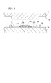
図2は、図1中のII−II線矢視断面、すなわち、接合部16の水平方向に沿う断面を模式的に示した水平方向断面模式図である。後述するように、樹脂複合材の端部同士を単純に加熱・加圧することで得られる接合部では、不連続繊維22がランダムに絡み合うことはない。これに対し、樹脂複合材製構造体10における接合部16に存在する不連続繊維22の繊維方向は、図2に示すようにランダムである。換言すれば、接合部16では、不連続繊維22同士がランダムに絡み合っている。この理由については後述する。
FIG. 2 is a horizontal cross-sectional schematic view schematically showing a cross section taken along line II-II in FIG. 1, that is, a cross section along the horizontal direction of the
この場合、樹脂複合材製構造体10の両端面は、ともに平坦面である。すなわち、第1部位18、接合部16及び第2部位20は面一として連なり、第1部位18と接合部16の間、又は接合部16と第2部位20との間に視認し得るような明確な段差は存在しない。
In this case, both end surfaces of the resin
また、第1部位18と接合部16の間、接合部16と第2部位20との間に、明確な境界は存在しない。すなわち、樹脂複合材製構造体10は、いわゆるシームレスである。ただし、図1においては、接合部16(すなわち、接合された端部同士)の位置を示すべく、該接合部16を仮想線で示している。
In addition, there is no clear boundary between the
すなわち、樹脂複合材製構造体10は、2個の樹脂複合材12、14を接合一体化したものであるにも関わらず、段部が存在しない。このため、外観が平坦であることが望まれる構成部材とすることが可能となる。また、接合部16の厚みが大きくなることを回避することもできる。
That is, although the resin
さらに、この接合部16は、該接合部16に存在する不連続繊維22同士が絡み合っている(図2参照)ために、十分な接合強度及び剛性を示す。従って、第1の樹脂複合材12と第2の樹脂複合材14が、接合部16から分離することが回避される。
Furthermore, since the
すなわち、第1実施形態によれば、外観が良好であり、しかも、接合強度及び剛性に優れる樹脂複合材製構造体10が得られる。このような樹脂複合材製構造体10、10同士をさらに接合一体化することにより、大形状の部材を作製することができる。勿論、この部材も、外観が良好であり且つ接合強度及び剛性に優れる。このような部材は、例えば、自動車車体の構成部材として採用することができる。
That is, according to the first embodiment, it is possible to obtain the resin
第1実施形態に係る樹脂複合材製構造体10は、以下のようにして作製することができる。
The resin
はじめに、第1の樹脂複合材12と第2の樹脂複合材14を用意する。この時点では、第1の樹脂複合材12及び第2の樹脂複合材14の双方とも、単純な平板形状をなす。
First, a first
次に、これら第1の樹脂複合材12及び第2の樹脂複合材14の端部に切削加工(カッティング)を施し、図3Aに示すように、凹部24と凸部26(重畳部)からなる波形状部28a、28bをそれぞれ形成する。なお、波形状部28aと波形状部28bの位相は同一である。また、この場合、凸部26は略二等辺三角形状に突出し、その頂角は略90°である。従って、波形状部28a、28bは、歯形形状をなす。
Next, the end portions of the first
次に、波形状部28a、28bを含む端部を加熱するとともに加圧する。加熱と加圧は同一工程として行ってもよいが、別工程としても特に差し支えはない。以降では、加熱と加圧を別工程とする場合につき説明する。
Next, the end including the wave-shaped
波形状部28a、28bを加熱するための装置の一例としては、図4に示す加熱装置30が挙げられる。この加熱装置30につき概略説明する。
As an example of an apparatus for heating the
加熱装置30は、下側支持ブロック32と上側支持ブロック34を有する。この中の下側支持ブロック32には、その長手方向に沿って2個の挿入孔36a、36bが形成される。各挿入孔36a、36bには、図示しない制御回路に対して電気的に接続されたロッドヒータ38a、38bが挿入される。
The
また、下側支持ブロック32の上端面には、その幅方向略中央に、上側支持ブロック34に指向して突出するとともに、前記長手方向に沿って延在する長尺な係合突部40が設けられる。従って、下側支持ブロック32の上端面には、係合突部40を挟んで、第1平坦面42a及び第2平坦面42bが形成される。さらに、係合突部40の上端部には、複数個のボルト止穴44が形成される。
In addition, on the upper end surface of the
一方の上側支持ブロック34には、前記係合突部40に対応する位置に係合溝46が形成される。上側支持ブロック34が下側支持ブロック32に重畳された際には、前記係合突部40は、この係合溝46に係合する。
One
上側支持ブロック34にも、前記挿入孔36a、36bに対して鉛直上方となる位置に挿入孔36c、36dが形成される。この挿入孔36c、36dには、ロッドヒータ38c、38dが挿入される。
In the
上側支持ブロック34には、その上端面から前記係合溝46の天井面に到達するようにして複数個のボルト通穴48が貫通形成される。各ボルト通穴48に通されたボルト50は、前記ボルト止穴44に螺合される。
A plurality of bolt through
波形状部28a、28bに対する加熱は、上記のように構成される加熱装置30を用い、以下のようにして行われる。
The heating of the wave-shaped
先ず、第1平坦面42a、第2平坦面42bに、第1の樹脂複合材12の波形状部28a、第2の樹脂複合材14の波形状部28bをそれぞれ載置する。
First, the
その後、上側支持ブロック34が、係合溝46に下側支持ブロック32の係合突部40が挿入されるようにして下側支持ブロック32に重畳される。下側支持ブロック32と上側支持ブロック34は、ボルト通穴48に通されたボルト50がボルト止穴44に螺合されることにより連結される。その結果、第1樹脂複合材における波形状部28aを含む一端部と、第2樹脂複合材における波形状部28bを含む一端部とが、下側支持ブロック32と上側支持ブロック34によって挟持される。さらに、挿入孔36a〜36dにロッドヒータ38a〜38dがそれぞれ挿入される。
Thereafter, the
この状態で、前記制御回路の制御作用下にロッドヒータ38a〜38dに通電がなされる。これによりロッドヒータ38a〜38dが発熱し、下側支持ブロック32と上側支持ブロック34によって挟持された第1の樹脂複合材12の一端部(波形状部28a)、及び第2の樹脂複合材14の一端部(波形状部28b)が加熱される。その結果、波形状部28a、28bを含む各端部が軟化する。
In this state, the
次に、第1の樹脂複合材12及び第2の樹脂複合材14を、成型するための型に移す。このような型の一例としては、図5に示す成形型52が挙げられる。
Next, the first
ここで、成形型52は、固定型である下型54と、図示しない昇降機構の作用下に下型54に対して接近又は離間するように変位する上型56とを有し、下型54には、略矩形状の枠体58が位置決め固定されている。第1の樹脂複合材12と第2の樹脂複合材14は、枠体58内に収容されるとともに、加熱された端部同士が重畳される。なお、図5においては、加熱された端部(加熱部位)を、ハッチングを付すことで示している。
Here, the molding die 52 includes a
この際には、図3Bに示すように、波形状部28a、28bの凸部26、26同士を重畳する。このため、互いに対向する凹部24、24同士の間に非重畳空間60が形成される。
At this time, as shown in FIG. 3B, the
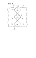
図6は、前記非重畳空間60を、その近傍とともに示した要部拡大図である。この場合、非重畳空間60は略菱形形状をなす。第1実施形態においては、この非重畳空間60の面積S1と、凸部26、26同士の重畳された部位の面積S2とが同等となるように、凸部26、26同士が重畳される。すなわち、S2/S1=1が成立する。
FIG. 6 is an enlarged view of a main part showing the
第2の樹脂複合材14における加熱部位が第1の樹脂複合材12の加熱部位に重畳されると、図5に示すように、第2の樹脂複合材14の非加熱部位が下型54に当接する。加熱部位(端部)は軟化しているので、該加熱部位が起点となって容易に撓むからである。
When the heated part of the second
この状態で、前記昇降機構が付勢されることにより、図7に示すように、上型56が降下する。これにより、重畳された端部同士(加熱部位同士)が圧潰されて一体化し、接合部16が形成される。なお、図7中のハッチングは図5同様に加熱部位を示し、断面を示しているのではない。また、ハッチング同士が重なっている部分は、圧潰によって混ざり合った(一体化した)端部同士を表す。
In this state, when the lifting mechanism is biased, the
圧潰に際しては、重畳された凸部26を構成していた母材(熱可塑性樹脂)が、図6に矢印で示すように流動する。その結果、非重畳空間60が母材及び不連続繊維22で充填されるとともに、凸部26、26同士の重畳による段差が解消される。このため、接合部16は、平坦部として形成される。なお、第1の樹脂複合材12及び第2の樹脂複合材14が延伸するときには、これら第1の樹脂複合材12及び第2の樹脂複合材14の端部が枠体58によって堰止される。
At the time of crushing, the base material (thermoplastic resin) constituting the superimposed
その後、接合部16を冷却硬化することにより、図1及び図3Cに示すように、第1の樹脂複合材12の非加熱部位を主体とする第1部位18と、接合部16と、第2の樹脂複合材14の非加熱部位を主体とする第2部位20とを有し、且つこれら第1部位18、接合部16及び第2部位20に段差や明確な境界が存在しない平坦な樹脂複合材製構造体10が得られるに至る。
Thereafter, the joint 16 is cooled and hardened, as shown in FIGS. 1 and 3C, the
重畳された加熱部位同士を圧潰する際、母材及び不連続繊維22が上記したような流動を起こす(図6参照)ことに伴い、接合部16では、不連続繊維22同士がランダムに絡み合う。このため、接合部16の強度及び剛性が優れたものとなる。
When crushing the overlapping heating sites, the
これに対し、図8A及び図8Bに示すように波形状部28a、28bが形成されていない平板形状の第1の樹脂複合材62及び第2の樹脂複合材64の端部同士を加熱して重畳し、圧潰を行った場合、その接合部では、不連続繊維22がランダムに絡み合うことはない。この理由は、重畳された端部同士を圧潰する際、母材及び不連続繊維22に上記したような流動が起こらないためであると推察される。そして、このような接合部では、樹脂溶着によって形成された接合部の強度・剛性を上回ることは困難である。
On the other hand, as shown in FIGS. 8A and 8B, the end portions of the first
以上のように、端部に波形状部28a、28bを形成し、これら波形状部28a、28b同士を重畳して接合一体化することにより、十分な強度及び剛性を示す接合部16を具備する樹脂複合材製構造体10を得ることができる。
As described above, the
なお、波形状部として、歯形形状をなすものを例示しているが、特にこれに限定されるものではない。別の一例としては、図9A〜図9Cに示すように、正弦波形状の波形状部28c、28dが挙げられる。この場合も、図3A〜図3Cに示す場合に準拠して非重畳空間60が充填され、不連続繊維22の繊維方向がランダムな接合部16が形成される。
In addition, although the thing which makes a tooth profile shape is illustrated as a waveform part, it is not specifically limited to this. As another example, as shown in FIGS. 9A to 9C, sinusoidal wave shapes 28 c and 28 d can be cited. Also in this case, the
上記した第1実施形態では、重畳する端部の各々に波形状部28a、28b、28c、28dを形成するようにしているが、波形状部は、重畳する端部の少なくとも一方に形成すればよい。さらに、接合する樹脂複合材は、平板形状のものに限定されるものではなく、立体形状が付与されたものであってもよい。以下、これにつき第2実施形態として説明する。
In the first embodiment described above, the
図10は、第2実施形態に係る樹脂複合材製構造体70の概略全体斜視図である。この樹脂複合材製構造体70は、開口が図10における下方に臨む断面コの字形状をなし、長尺な第1の樹脂複合材72と、短尺な第2の樹脂複合材74と、長尺な第3の樹脂複合材76とが長手方向に沿ってこの順序で連なるようにして接合一体化されたものである。ここで、第1の樹脂複合材72と第2の樹脂複合材74の間、第2の樹脂複合材74と第3の樹脂複合材76との間には、段差及び明確な境界は存在しない。すなわち、この場合も、樹脂複合材製構造体70の両端面は、シームレスな平坦面をなす。ただし、図10においては、接合前の第2の樹脂複合材74の位置を示すべく、該第2の樹脂複合材74からなる部位を仮想線で示している。
FIG. 10 is a schematic overall perspective view of a resin
なお、第2実施形態では、第2の樹脂複合材74の両端部にのみ波形状部78a、78bが形成され、第1の樹脂複合材72及び第3の樹脂複合材76の端部は直線形状である(図11参照)。この直線形状の各端部に前記波形状部78a、78bが重畳され、圧潰されることによって接合部が形成される。以上については、後述する。
In the second embodiment, the
第1の樹脂複合材72、第2の樹脂複合材74及び第3の樹脂複合材76は、第1実施形態と同様に、熱可塑性樹脂からなる母材中に不連続繊維22(図2参照)がランダムに分散した繊維強化樹脂である。不連続繊維22はガラス繊維であってもよいが、炭素繊維が一層好適である。
As in the first embodiment, the first
この樹脂複合材製構造体70の接合部においても、不連続繊維22の繊維方向はランダムである。すなわち、図2と同様に不連続繊維22同士が絡み合った状態である。このため、第1実施形態と同様に、接合部の強度が優れたものとなる。
Also in the joint portion of the resin
次に、この樹脂複合材製構造体70の製造方法につき説明する。
Next, a method for manufacturing the resin
図11に示すように、第2実施形態では、接合前の第1の樹脂複合材72及び第3の樹脂複合材76は、断面コの字形状の長尺物からなる。また、上記したように、これら第1の樹脂複合材72及び第3の樹脂複合材76には、波形状部が形成されていない。
As shown in FIG. 11, in the second embodiment, the first
残余の第2の樹脂複合材74は、加熱前は、凹部80と凸部82からなる波形状部78a、78bがその両端部に形成された略平板形状体である。このような形状の第2の樹脂複合材74は、第1の樹脂複合材72及び第3の樹脂複合材76に比して短尺な平板の両端部に対してカッティングを施すことで作製することができる。
The remaining second
次に、第1の樹脂複合材72及び第3の樹脂複合材76を、成形するための型に移す。このような型の一例としては、図11に示す成形型84が挙げられる。
Next, the first
この成形型84につき概略説明すると、該成形型84は、固定型である下型86と、図示しない昇降機構の作用下に下型86に対して接近又は離間するように変位する上型88とを有する。この中の下型86は、基部89から突出した支持凸部90が設けられた、いわゆる凸型である。また、上型88は、前記支持凸部90が進入する進入凹部92が陥没形成された、いわゆる凹型である。進入凹部92には、上型88とは個別に昇降可能な押圧型(図示せず)が配設される。成形型84は、さらに、断面コの字形状の堰止部材94a、94bを具備する。
The molding die 84 will be described briefly. The molding die 84 includes a
第1の樹脂複合材72及び第3の樹脂複合材76は、前記下型86の支持凸部90に、該支持凸部90を覆うようにして載置される。その一方で、波形状部78a、78bが形成された第2の樹脂複合材74が、例えば、加熱炉によって全体が加熱される。加熱された第2の樹脂複合材74は軟化しているので、波形状部78a、78bが第1の樹脂複合材72及び第3の樹脂複合材76の端部に重畳されると、第2の樹脂複合材74において、支持凸部90の上端面から突出した部位は、該支持凸部90の縦壁に沿って容易に撓む。図11では、この状態を、第2の樹脂複合材74を第1の樹脂複合材72及び第3の樹脂複合材76から離間させて示している。
The first
第2の樹脂複合材74の波形状部78a、78bの凸部82が第1の樹脂複合材72及び第3の樹脂複合材76の端部に重畳されると、図12に示すように、第1の樹脂複合材72の端部と、第2の樹脂複合材74の波形状部78aの凹部80との間に非重畳空間96が形成される。凸部82において、非重畳空間96の面積S3と、第1の樹脂複合材72の端部に重畳された部位の面積S4とは同等である。すなわち、S4/S3=1が成り立つ。また、堰止部材94a、94bが第1の樹脂複合材72、第3の樹脂複合材76の各上端面の所定箇所に載置される。
図示しないが、第2の樹脂複合材74の波形状部78bの凹部80と、第3の樹脂複合材76の端部との間にも同様に非重畳空間96が形成される。また波形状部78bの凸部82において、第3の樹脂複合材76の端部に重畳された部位の面積と、非重畳空間96の面積は同等である。
Although not shown, the
その後、前記昇降機構の作用下に上型88(図11参照)が下型86に向かって降下する。その結果、支持凸部90が進入凹部92に進入する。上型88が最下点に到達すると、次に、進入凹部92内に配設された前記押圧型が降下し、波形状部78aと第1の樹脂複合材72の端部との重畳箇所から、波形状部78bと第3の樹脂複合材76の端部との重畳箇所にわたる範囲を押圧する。これにより、前記2個の重畳箇所が圧潰される。
Thereafter, the upper mold 88 (see FIG. 11) descends toward the
この際、第1の樹脂複合材72の端部に重畳された凸部82が、図12に矢印で示すように流動する。その結果、非重畳空間96が母材及び不連続繊維22で充填されるとともに、凸部82と前記端部の重畳による段差が解消される。このため、接合部は、平坦部として形成される。なお、第2の樹脂複合材74が延伸するときには、第2の樹脂複合材74の端部が堰止部材94a、94bによって堰止される。勿論、第3の樹脂複合材76の端部に重畳された凸部82においても同様である。
At this time, the
その後、接合部を冷却硬化することにより、図10に示すように、長尺な第1の樹脂複合材72と、短尺な第2の樹脂複合材74と、長尺な第3の樹脂複合材76とが長手方向に沿ってこの順序で連なるようにして接合一体化され、第1の樹脂複合材72と第2の樹脂複合材74の接合部、及び第2の樹脂複合材74と第3の樹脂複合材76の接合部に段差や明確な境界が存在しない平坦な樹脂複合材製構造体70が得られるに至る。
Thereafter, the joint is cooled and cured, as shown in FIG. 10, the long first
第1実施形態と同様に、第2実施形態においても、重畳箇所において母材及び不連続繊維22が上記したような流動を起こす(図12参照)ことに伴い、接合部では、不連続繊維22の繊維方向がランダムとなる。すなわち、不連続繊維22同士が絡み合う。このため、接合部の強度及び剛性が優れたものとなる。
Similar to the first embodiment, in the second embodiment, the base material and the
本発明は、上記した第1及び第2実施形態に特に限定されるものではなく、本発明の要旨を逸脱しない範囲で種々の変更が可能である。 The present invention is not particularly limited to the first and second embodiments described above, and various modifications can be made without departing from the scope of the present invention.
例えば、S2/S1=1(図6参照)とする必要は特になく、0.75≦S2/S1≦2とするようにしてもよい。S2/S1が0.75以上1未満のときには、接合部の強度を維持しつつ、その厚みを、第1部位18や第2部位20の厚みに比して小さくすることができる。すなわち、接合部を、陥没部として形成することが可能である。一方、S2/S1が1よりも大きく2以下であるときには、接合部の強度を一層向上させることができる。この場合、接合部は、隆起部として形成される。以上においては、例えば、陥没部又は隆起部を意匠形状として活用するようにすればよい。
For example, it is not particularly necessary to set S 2 / S 1 = 1 (see FIG. 6), and 0.75 ≦ S 2 / S 1 ≦ 2 may be satisfied. When S 2 / S 1 is 0.75 or more and less than 1, the thickness can be reduced as compared with the thickness of the
勿論、第2実施形態においても、S4/S3=1(図12参照)とする必要は特になく、0.75≦S4/S3≦2とするようにしてもよい。
Of course, in the second embodiment, it is not particularly necessary to set S 4 / S 3 = 1 (see FIG. 12), and 0.75 ≦ S 4 / S 3 ≦ 2 may be satisfied.
また、第2実施形態では、第1の樹脂複合材72と第2の樹脂複合材74を接合一体化すると同時に、第2の樹脂複合材74と第3の樹脂複合材76を接合一体化するようにしているが、例えば、第1の樹脂複合材72、第2の樹脂複合材74及び第3の樹脂複合材76が大形状のものであり、全重畳部位を成形型に収容することが困難である場合には、第1の樹脂複合材72と第2の樹脂複合材74とを先ず接合一体化した後、第2の樹脂複合材74と第3の樹脂複合材76とを接合一体化するようにしてもよい。換言すれば、第1の樹脂複合材72と第2の樹脂複合材74の接合一体化と、第2の樹脂複合材74と第3の樹脂複合材76の接合一体化を別個の工程として実施すればよい。
In the second embodiment, the first
さらに、波形状部28a〜28d、78a、78bは、樹脂複合材12、14、74を成形加工によって作製する際に同時に形成することも可能である。
Further, the
さらにまた、本発明においては、波形状部28a〜28d、78a、78bを形成する場合に特に限定されるものではなく、相手材に重畳する重畳部と、相手材に重畳されることなく非重畳空間を形成し得る部位とが存在すればよい。
Furthermore, in the present invention, there is no particular limitation when forming the
また、第1実施形態及び第2実施形態では、樹脂複合材12、14、74に波形状部28a〜28d、78a、78bを形成して重畳部である凸部26、82を設けるようにしているが、図13及び図14に示すように、別の樹脂複合材98、100そのものを重畳部とするようにしてもよい。
In the first embodiment and the second embodiment, the
図13に示す実施形態につき説明すると、この場合、第1の樹脂複合材62及び第2の樹脂複合材64は、単純な平板形状である。そして、これら第1の樹脂複合材62と第2の樹脂複合材64との間に橋架されるようにして、略菱形形状の樹脂複合材98が複数個重畳されるとともに、第1の樹脂複合材62と樹脂複合材98との間、及び樹脂複合材98と第2の樹脂複合材64との間に非重畳空間102が形成される。なお、この場合、隣接する樹脂複合材98、98同士の頂部が重畳されるようにしてもよい。
The embodiment shown in FIG. 13 will be described. In this case, the first
一方、図14に示す実施形態においては、第1の樹脂複合材62と第2の樹脂複合材64との間に橋架された樹脂複合材100は、略長方形をなす平板形状である。そして、互いに離間した樹脂複合材100、100同士の間に、非重畳空間104が形成される。
On the other hand, in the embodiment shown in FIG. 14, the
いずれの場合においても、第1実施形態及び第2実施形態と同様に、樹脂複合材98、100の母材である熱可塑性樹脂と、これに含まれる不連続繊維22とが非重畳空間102、104を充填するように流動する。従って、不連続繊維22の繊維方向がランダムな接合部が得られる。
In any case, as in the first and second embodiments, the thermoplastic resin that is the base material of the
10、70…樹脂複合材製構造体
12、14、62、64、72、74、76、98、100…樹脂複合材
16…接合部 24、80…凹部
26、82…凸部
28a〜28d、78a、78b…波形状部
30…加熱装置 38a〜38d…ロッドヒータ
52、84…成形型 54、86…下型
56、88…上型 58…枠体
60、96、100、102…非重畳空間 90…支持凸部
92…進入凹部 94a、94b…堰止部材
DESCRIPTION OF
Claims (5)
前記第1の樹脂複合材と前記第2の樹脂複合材の端部同士の間に、前記端部同士に跨る重畳部と、該重畳部以外の部位の非重畳空間とを形成する重畳工程と、
前記重畳部と前記端部に荷重を付与することで前記非重畳空間を充填するとともに前記重畳部と前記端部とを接合一体化して、前記不連続繊維の繊維方向がランダムな接合部を備える樹脂複合材製構造体を得る接合工程と、
前記重畳工程を行う前、前記重畳工程を行った後、又は前記接合工程の最中のいずれかで、少なくとも前記重畳部を加熱して軟化させる加熱工程と、
を有し、
前記重畳工程で、不連続繊維を含み前記第1の樹脂複合材及び前記第2の樹脂複合材とは別の樹脂複合材を1個以上用いて前記重畳部とし、該重畳部を、互いに離間した前記第1の樹脂複合材と前記第2の樹脂複合材とに橋架されるように該第1の樹脂複合材及び該第2の樹脂複合材の双方に重畳することを特徴とする樹脂複合材製構造体の製造方法。 A method for producing a resin composite material structure, in which a first resin composite material containing discontinuous fibers and a second resin composite material are joined together to obtain a resin composite material structure,
A superimposing step of forming a superposed portion straddling the end portions and a non-overlapping space other than the superposed portion between the end portions of the first resin composite material and the second resin composite material; ,
The non-overlapping space is filled by applying a load to the overlapping part and the end part, and the overlapping part and the end part are joined and integrated, and the discontinuous fiber has a random joining direction. A bonding step for obtaining a resin composite structure;
Before performing the superimposing step, after performing the superimposing step, or during the joining step, at least a heating step of heating and softening the overlapping portion;
I have a,
In the superimposing step, at least one resin composite material including discontinuous fibers and different from the first resin composite material and the second resin composite material is used as the superposition portion, and the superposition portions are separated from each other. A resin composite that overlaps both the first resin composite and the second resin composite so as to be bridged by the first resin composite and the second resin composite A method for manufacturing a material structure.
0.75≦重畳部の重畳された部位の面積/非重畳空間の面積≦2
の関係を成立させることを特徴とする樹脂複合材製構造体の製造方法。 The manufacturing method of claim 1 Symbol placement, and the area of the superimposed portions of the superimposed portion, between the area of the non-overlapping space,
0.75 ≦ area of the overlapped portion / area of the non-overlapping space ≦ 2
The manufacturing method of the structure made from a resin composite material characterized by establishing the relationship of these.
重畳部の重畳された部位の面積/非重畳空間の面積=1
の関係を成立させることを特徴とする樹脂複合材製構造体の製造方法。 In the manufacturing method according to claim 2 , between the area of the superposed part of the superposition part and the area of the non-superimposition space,
Area of superposed part / area of non-superimposed space = 1
The manufacturing method of the structure made from a resin composite material characterized by establishing the relationship of these.
前記第2の重畳部と前記第2の樹脂複合材及び前記第3の樹脂複合材の端部に荷重を付与することで前記第2の非重畳空間を充填するとともに前記第2の重畳部と前記第2の樹脂複合材及び前記第3の樹脂複合材の端部とを接合一体化して、前記不連続繊維の繊維方向がランダムな第2の接合部を備える樹脂複合材製構造体を得る第2の接合工程と、
前記第2の重畳工程を行う前、前記第2の重畳工程を行った後、又は前記第2の接合工程の最中のいずれかで、少なくとも前記第2の重畳部を加熱して軟化させる第2の加熱工程と、
を有することを特徴とする樹脂複合材製構造体の製造方法。 The manufacturing method according to any one of claims 1 to 3 , further comprising an end between the second resin composite material and ends of the third resin composite material including discontinuous fibers. A second superimposing step for forming a second superimposing portion straddling the parts and a second non-superimposing space of a part other than the second superimposing portion;
Filling the second non-overlapping space by applying a load to the second overlapping portion, the second resin composite material, and the end of the third resin composite material, and the second overlapping portion The second resin composite material and the end portion of the third resin composite material are joined and integrated to obtain a resin composite material structure including a second joint portion in which the fiber directions of the discontinuous fibers are random. A second joining step;
Before performing the second overlapping step, after performing the second overlapping step, or during the second bonding step, at least the second overlapping portion is heated and softened. 2 heating steps;
The manufacturing method of the structure made from a resin composite material characterized by having.
Priority Applications (4)
| Application Number | Priority Date | Filing Date | Title |
|---|---|---|---|
| JP2013048599A JP5990480B2 (en) | 2013-03-12 | 2013-03-12 | Manufacturing method of resin composite structure |
| DE201410204113 DE102014204113A1 (en) | 2013-03-12 | 2014-03-06 | Plastic composite structure and process for its production |
| CN201410082119.8A CN104044266B (en) | 2013-03-12 | 2014-03-07 | Resin compounded structure and the method being used for manufacturing resin compounded structure |
| US14/202,139 US9314990B2 (en) | 2013-03-12 | 2014-03-10 | Resin composite structure and method for producing the same |
Applications Claiming Priority (1)
| Application Number | Priority Date | Filing Date | Title |
|---|---|---|---|
| JP2013048599A JP5990480B2 (en) | 2013-03-12 | 2013-03-12 | Manufacturing method of resin composite structure |
Publications (3)
| Publication Number | Publication Date |
|---|---|
| JP2014172334A JP2014172334A (en) | 2014-09-22 |
| JP2014172334A5 JP2014172334A5 (en) | 2016-06-16 |
| JP5990480B2 true JP5990480B2 (en) | 2016-09-14 |
Family
ID=51419238
Family Applications (1)
| Application Number | Title | Priority Date | Filing Date |
|---|---|---|---|
| JP2013048599A Expired - Fee Related JP5990480B2 (en) | 2013-03-12 | 2013-03-12 | Manufacturing method of resin composite structure |
Country Status (4)
| Country | Link |
|---|---|
| US (1) | US9314990B2 (en) |
| JP (1) | JP5990480B2 (en) |
| CN (1) | CN104044266B (en) |
| DE (1) | DE102014204113A1 (en) |
Families Citing this family (6)
| Publication number | Priority date | Publication date | Assignee | Title |
|---|---|---|---|---|
| KR20190104988A (en) * | 2017-02-02 | 2019-09-11 | 도레이 카부시키가이샤 | Manufacturing method of fiber reinforced plastic |
| CA3048978A1 (en) | 2017-02-02 | 2018-08-09 | Toray Industries, Inc. | Method for producing fiber-reinforced plastic |
| CN111319269A (en) * | 2018-12-13 | 2020-06-23 | 财团法人金属工业研究发展中心 | Jointing device of thermoplastic composite board and jointing method using same |
| US20220410497A1 (en) * | 2021-06-23 | 2022-12-29 | Arris Composites Inc. | Modular thermoplastic composite structures |
| FR3134740A1 (en) * | 2022-04-20 | 2023-10-27 | Technip N-Power | Process for manufacturing a strip of composite material intended to form a tubular structure and corresponding installation |
| CN115214157A (en) * | 2022-06-16 | 2022-10-21 | 北京工业大学 | Node connection method of thermoplastic resin-based composite material pultrusion section bar |
Family Cites Families (7)
| Publication number | Priority date | Publication date | Assignee | Title |
|---|---|---|---|---|
| JP3169153B2 (en) * | 1993-12-28 | 2001-05-21 | トヨタ自動車株式会社 | How to join plastic members |
| JPH09314669A (en) * | 1996-05-30 | 1997-12-09 | Aisin Seiki Co Ltd | Bonding of resin parts |
| JP3859321B2 (en) | 1997-09-25 | 2006-12-20 | プレス工業株式会社 | Method of welding fiber reinforced resin moldings |
| JP2007313778A (en) * | 2006-05-26 | 2007-12-06 | Teijin Techno Products Ltd | Joining method of fiber-reinforced thermoplastic resin composite material |
| FR2933966B1 (en) * | 2008-07-15 | 2013-10-11 | Gerflor | JUNCTION BY RABBING TWO BANDS OF DEFORMABLE MATERIALS AND METHOD OF IMPLEMENTING SAME, AND THE PRODUCTS OBTAINED BY THE PROCESS |
| GB2489212B (en) * | 2011-03-15 | 2013-11-20 | Gurit Uk Ltd | Sandwich panel and manufacture thereof |
| JP2013158914A (en) * | 2012-02-01 | 2013-08-19 | Toyota Motor Corp | Welding structure and welding method |
-
2013
- 2013-03-12 JP JP2013048599A patent/JP5990480B2/en not_active Expired - Fee Related
-
2014
- 2014-03-06 DE DE201410204113 patent/DE102014204113A1/en not_active Withdrawn
- 2014-03-07 CN CN201410082119.8A patent/CN104044266B/en active Active
- 2014-03-10 US US14/202,139 patent/US9314990B2/en active Active
Also Published As
| Publication number | Publication date |
|---|---|
| US9314990B2 (en) | 2016-04-19 |
| JP2014172334A (en) | 2014-09-22 |
| DE102014204113A1 (en) | 2014-09-18 |
| US20140272243A1 (en) | 2014-09-18 |
| CN104044266B (en) | 2016-08-17 |
| CN104044266A (en) | 2014-09-17 |
Similar Documents
| Publication | Publication Date | Title |
|---|---|---|
| JP5990480B2 (en) | Manufacturing method of resin composite structure | |
| JP6286411B2 (en) | Method for manufacturing vehicle skeleton member | |
| CN105722661B (en) | The method for manufacturing component by organic plates | |
| JP7136625B2 (en) | Design features of dissimilar material reinforced blanks and extrudates for molding | |
| RU2595650C2 (en) | Self-reinforcing composite panel, in particular, for aircraft floor and method of making said panel | |
| JP6354662B2 (en) | Vehicle member joining structure and vehicle member joining method | |
| US20190283805A1 (en) | Vehicle frame structure | |
| JP6007132B2 (en) | Side panel | |
| WO2015055419A1 (en) | Battery housing, battery and method for producing a battery housing | |
| CA2969909C (en) | Method for manufacturing a sandwich panel | |
| EP2565021B1 (en) | A curable assembly and a method of forming a component from a curable assembly comprising a filler component | |
| US10513067B2 (en) | Metal/composite assembly method | |
| JP2015083869A (en) | Compound component | |
| TWI758381B (en) | Method for manufacturing a weldable metal-polymer multilayer composite | |
| GB2182703A (en) | Improvements relating to structural sandwich sheet material comprising two face sheets and two core sheets | |
| EP3319783B1 (en) | Bonding objects together | |
| JP6521135B2 (en) | Bonding structure of vehicle members and method of bonding vehicle members | |
| EP3409446A1 (en) | Method of creating large complex composite panels using co-consolidation of thermoplastic material subpanels | |
| US9919473B2 (en) | Method for producing fiber-reinforced resin bonded body | |
| JP6045431B2 (en) | Method and apparatus for joining fiber reinforced resin laminate and fiber reinforced resin material | |
| JP6521134B2 (en) | Bonding structure of vehicle members and method of bonding vehicle members | |
| JP7231439B2 (en) | Resin molding and its manufacturing method | |
| JP2007015187A (en) | Frp molding | |
| JP6491005B2 (en) | Method for manufacturing composite structure and temperature control panel | |
| KR20180074604A (en) | Insert designed to be fitted on a support and fixing assembly comprising one such insert |
Legal Events
| Date | Code | Title | Description |
|---|---|---|---|
| A621 | Written request for application examination |
Free format text: JAPANESE INTERMEDIATE CODE: A621 Effective date: 20151126 |
|
| A521 | Request for written amendment filed |
Free format text: JAPANESE INTERMEDIATE CODE: A523 Effective date: 20160415 |
|
| A977 | Report on retrieval |
Free format text: JAPANESE INTERMEDIATE CODE: A971007 Effective date: 20160623 |
|
| A131 | Notification of reasons for refusal |
Free format text: JAPANESE INTERMEDIATE CODE: A131 Effective date: 20160628 |
|
| A521 | Request for written amendment filed |
Free format text: JAPANESE INTERMEDIATE CODE: A523 Effective date: 20160715 |
|
| TRDD | Decision of grant or rejection written | ||
| A01 | Written decision to grant a patent or to grant a registration (utility model) |
Free format text: JAPANESE INTERMEDIATE CODE: A01 Effective date: 20160809 |
|
| A61 | First payment of annual fees (during grant procedure) |
Free format text: JAPANESE INTERMEDIATE CODE: A61 Effective date: 20160815 |
|
| R150 | Certificate of patent or registration of utility model |
Ref document number: 5990480 Country of ref document: JP Free format text: JAPANESE INTERMEDIATE CODE: R150 |
|
| R250 | Receipt of annual fees |
Free format text: JAPANESE INTERMEDIATE CODE: R250 |
|
| LAPS | Cancellation because of no payment of annual fees |