JP5988994B2 - Turbine engine blades with improved stacking rules - Google Patents
Turbine engine blades with improved stacking rules Download PDFInfo
- Publication number
- JP5988994B2 JP5988994B2 JP2013543865A JP2013543865A JP5988994B2 JP 5988994 B2 JP5988994 B2 JP 5988994B2 JP 2013543865 A JP2013543865 A JP 2013543865A JP 2013543865 A JP2013543865 A JP 2013543865A JP 5988994 B2 JP5988994 B2 JP 5988994B2
- Authority
- JP
- Japan
- Prior art keywords
- blade
- compressor
- turbomachine
- curvature
- wing
- Prior art date
- Legal status (The legal status is an assumption and is not a legal conclusion. Google has not performed a legal analysis and makes no representation as to the accuracy of the status listed.)
- Active
Links
- 230000009466 transformation Effects 0.000 claims description 3
- 230000008859 change Effects 0.000 description 21
- 230000006872 improvement Effects 0.000 description 7
- 230000000694 effects Effects 0.000 description 5
- 238000010586 diagram Methods 0.000 description 4
- 230000000630 rising effect Effects 0.000 description 4
- 238000005452 bending Methods 0.000 description 2
- 238000006243 chemical reaction Methods 0.000 description 2
- 230000006835 compression Effects 0.000 description 2
- 238000007906 compression Methods 0.000 description 2
- 230000002411 adverse Effects 0.000 description 1
- 238000013459 approach Methods 0.000 description 1
- 230000009286 beneficial effect Effects 0.000 description 1
- 230000015572 biosynthetic process Effects 0.000 description 1
- 238000002485 combustion reaction Methods 0.000 description 1
- 238000007796 conventional method Methods 0.000 description 1
- 238000012937 correction Methods 0.000 description 1
- 238000013461 design Methods 0.000 description 1
- 239000012530 fluid Substances 0.000 description 1
- 230000005484 gravity Effects 0.000 description 1
- 238000004519 manufacturing process Methods 0.000 description 1
- 238000000034 method Methods 0.000 description 1
- 238000012986 modification Methods 0.000 description 1
- 230000004048 modification Effects 0.000 description 1
- 230000008569 process Effects 0.000 description 1
- 238000012545 processing Methods 0.000 description 1
- 230000007480 spreading Effects 0.000 description 1
- 238000012360 testing method Methods 0.000 description 1
- 238000011144 upstream manufacturing Methods 0.000 description 1
Images


Classifications
-
- F—MECHANICAL ENGINEERING; LIGHTING; HEATING; WEAPONS; BLASTING
- F01—MACHINES OR ENGINES IN GENERAL; ENGINE PLANTS IN GENERAL; STEAM ENGINES
- F01D—NON-POSITIVE DISPLACEMENT MACHINES OR ENGINES, e.g. STEAM TURBINES
- F01D5/00—Blades; Blade-carrying members; Heating, heat-insulating, cooling or antivibration means on the blades or the members
- F01D5/12—Blades
- F01D5/14—Form or construction
- F01D5/141—Shape, i.e. outer, aerodynamic form
- F01D5/145—Means for influencing boundary layers or secondary circulations
-
- F—MECHANICAL ENGINEERING; LIGHTING; HEATING; WEAPONS; BLASTING
- F01—MACHINES OR ENGINES IN GENERAL; ENGINE PLANTS IN GENERAL; STEAM ENGINES
- F01D—NON-POSITIVE DISPLACEMENT MACHINES OR ENGINES, e.g. STEAM TURBINES
- F01D5/00—Blades; Blade-carrying members; Heating, heat-insulating, cooling or antivibration means on the blades or the members
- F01D5/12—Blades
- F01D5/14—Form or construction
- F01D5/20—Specially-shaped blade tips to seal space between tips and stator
-
- F—MECHANICAL ENGINEERING; LIGHTING; HEATING; WEAPONS; BLASTING
- F04—POSITIVE - DISPLACEMENT MACHINES FOR LIQUIDS; PUMPS FOR LIQUIDS OR ELASTIC FLUIDS
- F04D—NON-POSITIVE-DISPLACEMENT PUMPS
- F04D29/00—Details, component parts, or accessories
- F04D29/26—Rotors specially for elastic fluids
- F04D29/32—Rotors specially for elastic fluids for axial flow pumps
- F04D29/321—Rotors specially for elastic fluids for axial flow pumps for axial flow compressors
- F04D29/324—Blades
-
- F—MECHANICAL ENGINEERING; LIGHTING; HEATING; WEAPONS; BLASTING
- F05—INDEXING SCHEMES RELATING TO ENGINES OR PUMPS IN VARIOUS SUBCLASSES OF CLASSES F01-F04
- F05D—INDEXING SCHEME FOR ASPECTS RELATING TO NON-POSITIVE-DISPLACEMENT MACHINES OR ENGINES, GAS-TURBINES OR JET-PROPULSION PLANTS
- F05D2240/00—Components
- F05D2240/20—Rotors
- F05D2240/30—Characteristics of rotor blades, i.e. of any element transforming dynamic fluid energy to or from rotational energy and being attached to a rotor
- F05D2240/307—Characteristics of rotor blades, i.e. of any element transforming dynamic fluid energy to or from rotational energy and being attached to a rotor related to the tip of a rotor blade
-
- F—MECHANICAL ENGINEERING; LIGHTING; HEATING; WEAPONS; BLASTING
- F05—INDEXING SCHEMES RELATING TO ENGINES OR PUMPS IN VARIOUS SUBCLASSES OF CLASSES F01-F04
- F05D—INDEXING SCHEME FOR ASPECTS RELATING TO NON-POSITIVE-DISPLACEMENT MACHINES OR ENGINES, GAS-TURBINES OR JET-PROPULSION PLANTS
- F05D2250/00—Geometry
- F05D2250/70—Shape
- F05D2250/71—Shape curved
- F05D2250/713—Shape curved inflexed
-
- Y—GENERAL TAGGING OF NEW TECHNOLOGICAL DEVELOPMENTS; GENERAL TAGGING OF CROSS-SECTIONAL TECHNOLOGIES SPANNING OVER SEVERAL SECTIONS OF THE IPC; TECHNICAL SUBJECTS COVERED BY FORMER USPC CROSS-REFERENCE ART COLLECTIONS [XRACs] AND DIGESTS
- Y02—TECHNOLOGIES OR APPLICATIONS FOR MITIGATION OR ADAPTATION AGAINST CLIMATE CHANGE
- Y02T—CLIMATE CHANGE MITIGATION TECHNOLOGIES RELATED TO TRANSPORTATION
- Y02T50/00—Aeronautics or air transport
- Y02T50/60—Efficient propulsion technologies, e.g. for aircraft
Landscapes
- Engineering & Computer Science (AREA)
- Mechanical Engineering (AREA)
- General Engineering & Computer Science (AREA)
- Physics & Mathematics (AREA)
- Fluid Mechanics (AREA)
- Structures Of Non-Positive Displacement Pumps (AREA)
- Turbine Rotor Nozzle Sealing (AREA)
Description
本発明の分野は熱力学の分野であり、より具体的にはターボ機械の圧縮機用ブレードの分野である。 The field of the invention is that of thermodynamics, more specifically that of turbomachine compressor blades.
航空用ターボ機械は従来、気体が流れる方向の上流から下流に向かって、ファン、たとえば低圧圧縮機および高圧圧縮機などの1つ以上の圧縮機段、燃焼室、たとえば高圧タービンおよび低圧タービンなどの1つ以上のタービン段、ならびにガス排出ノズルからなる。1つまたは複数の圧縮機は、案内羽根として知られる複数組のステータ羽根配列を通り越して回転する複数組のロータ羽根配列の形態で、製造される。ロータ羽根配列は、ターボ機械のロータによって駆動されるディスクの周囲に均等に配置され、その翼はロータディスクと空気流路を囲う筐体との間で半径方向に延在する。 Aviation turbomachines conventionally have fans, such as one or more compressor stages such as low pressure compressors and high pressure compressors, combustion chambers such as high pressure turbines and low pressure turbines, from upstream to downstream in the direction of gas flow. It consists of one or more turbine stages, as well as a gas discharge nozzle. One or more compressors are manufactured in the form of multiple sets of rotor blades that rotate past multiple sets of stator blades known as guide blades. The rotor blade arrangement is evenly arranged around the disk driven by the rotor of the turbomachine, and its blades extend radially between the rotor disk and the housing surrounding the air flow path.
各ロータブレードは、その上で流路の空気がブレード翼の近傍に広がる平均圧力よりも高い圧力になる圧力面と、その上で空気がこの平均圧力と比較して低い圧力になる吸引面とを含む。するとこれはブレードの外端に空気回路を確立させ、ブレードと筐体との間にある間隙を通じて圧力面から吸引面へと空気を通過させる。周知の方法において、この空気の循環は、ブレードの翼弦の全長に沿って発達し、ブレードの後縁の下流に広がるブレード端間隙渦と称される渦の形態を取る。 Each rotor blade has a pressure surface on which the air in the flow path is higher than the average pressure spreading near the blade blades, and a suction surface on which the air is lower than this average pressure. including. This in turn establishes an air circuit at the outer end of the blade and allows air to pass from the pressure surface to the suction surface through a gap between the blade and the housing. In a known manner, this air circulation takes the form of a vortex called blade edge gap vortex that develops along the entire length of the blade chord and extends downstream of the trailing edge of the blade.
この渦の存在は、圧縮機のさらに下流の段における流れを妨害し、圧縮機の効率に悪影響を及ぼす損失を生じる。したがって、この渦を排除すること、または最低限でもそれが運ぶ空気の流量を低減することが、望ましいだろう。 The presence of this vortex impedes the flow in the downstream stages of the compressor and causes losses that adversely affect the efficiency of the compressor. Therefore, it would be desirable to eliminate this vortex, or at a minimum reduce the flow of air it carries.
この渦を制御しようとする試みがなされてきたが、これらはたとえば圧縮機を囲む筐体に適用される処理、または「トレンチ」すなわち筐体に空けられた空洞の形成を、含む。このような処理の一例は、本出願人による仏国特許発明第2940374号明細書に記載されている。これらのすべては、ターボ機械の製造に追加コストが発生し、特定の動作点における効率という観点で圧縮機の性能を低下させる可能性があるという不都合を有する。 Attempts have been made to control this vortex, which includes, for example, a process applied to the enclosure surrounding the compressor, or the formation of a “trench” or cavity vacated in the enclosure. An example of such processing is described in French Patent No. 2940374 by the present applicant. All of these have the disadvantage that additional costs are incurred in the manufacture of the turbomachine and can reduce the performance of the compressor in terms of efficiency at a particular operating point.
この渦が圧縮機またはタービン段の効率に対して及ぼす影響を減じる試みとしての特許出願もなされており、これらはたとえば米国特許出願公開第2010/0054946号明細書および欧州特許第1953341号明細書を含む。これらの出願は、前縁に付与された形状を変更することによって、すなわちブレードの根元から先端までの間のその前縁に沿った掃引角度を変更することによって、ブレードの形状を変更しようとするものである。これらは、該米国明細書の図12を例外として、ブレードの高さに沿った要素プロファイルのスタッキングラインに対する変更に関して、いかなる指示も与えていない。 Patent applications have also been made in an attempt to reduce the effect of this vortex on the efficiency of a compressor or turbine stage, such as US 2010/0054946 and EP 1953341. Including. These applications attempt to change the shape of the blade by changing the shape imparted to the leading edge, i.e. changing the sweep angle along its leading edge from the root to the tip of the blade. Is. They do not give any indication regarding changes to the stacking line of the element profile along the height of the blade, with the exception of FIG. 12 of the US specification.
さらに、米国特許第6341942号明細書は、その質量を増加させることなくその曲げ剛性を増加させることを目的として、圧縮機ブレードの高さに沿った起伏を記載している。これは1つの起伏がブレード上の高い位置にあってもよいことを示しているものの、これに関わる曲率の転換点の位置を特定するものではなく、ましてや二重屈曲の場合に屈曲の低い方の点の位置を示すものでもない。また、ブレードの振動挙動の問題を強調することによって、演繹的に、ブレード端間隙渦を制御することによって段の効率をどのように改善するかを検討する当業者の役に立つものでもない。 Furthermore, US Pat. No. 6,341,942 describes relief along the height of the compressor blade with the aim of increasing its flexural rigidity without increasing its mass. Although this indicates that one undulation may be at a higher position on the blade, it does not specify the position of the turning point of the associated curvature, and in the case of double bending, the one with the lower bending It does not indicate the position of the point. Nor is it helpful to those skilled in the art to consider how to improve the efficiency of the stage by controlling the blade end gap vortices a priori by highlighting the problem of blade vibration behavior.
本発明の目的は、圧縮機筐体をまったく変更することなく翼の圧力面と吸引面との間のこの漏れ流の影響を低減する特殊な形状をブレードに付与することによって、ターボ機械の圧縮機またはタービン段の効率を可能な限り改善することである。 It is an object of the present invention to provide turbomachine compression by imparting a special shape to the blade that reduces the effect of this leakage flow between the pressure and suction surfaces of the blades without any change in the compressor housing. To improve the efficiency of the machine or turbine stage as much as possible.
上記の目的のため、本発明の対象はターボ機械ブレードであって、その翼がブレード根元と翼端との間で半径方向に、前縁と後縁との間で軸方向に、そして圧力面と吸引面との間で接線方向に延在し、前記ブレードのプロファイルは、断面のすべての重心をつなげたスタッキングラインとして知られる線に沿って互いに積み重ねられた、羽根断面の形状の、一連の基本プロファイルからなり、ブレード根元から半径方向に延在する少なくとも1つの平面上への翼の前記スタッキングラインの投影はその曲率の方向の二重接線転換を含み、この転換は翼の高さの最後の30パーセント以内に位置し、投影面はブレードの翼弦に対して実質的に直角に配向されている。 For the above purpose, the subject of the present invention is a turbomachine blade, whose wings are radially between the blade root and tip, axially between the leading and trailing edges, and pressure surface The blade profile extends in a tangential direction between the blade and the suction surface, and the blade profile is a series of blade cross-sectional shapes stacked together along a line known as a stacking line connecting all the centroids of the cross-section The projection of the wing stacking line on the at least one plane consisting of the basic profile and extending radially from the blade root includes a double tangential transformation in the direction of its curvature, this transformation being the last of the wing height. The projection plane is oriented substantially perpendicular to the blade chord.
これらの積み重ねの修正は、流れのより良い誘導を通じて、翼によって発生したブレード端間隙渦を減少させることができるようにする。 These stacking modifications allow blade tip clearance vortices generated by the blades to be reduced through better flow guidance.
実際、転換がこれら最後の30パーセントよりも下に位置する場合には、本発明によって提供される有益な効果が維持されなくなることが、計算によって示されている。ブレード端よりも遠くにあるいずれかの起伏が及ぼす影響は、これらがブレード端間隙渦に緩衝する程度の弱さのため、小さくなるだろう。 In fact, calculations show that the beneficial effects provided by the present invention are not maintained if the conversion is below these last 30 percent. The effect of any undulations farther away from the blade edge will be small due to the weakness that they buffer into the blade edge gap vortex.
好ましくは、2つの接線転換点は翼の高さの最後の10パーセント以内に位置する。 Preferably, the two tangential turning points are located within the last 10 percent of the wing height.
別の特定の実施形態において、ブレードは軸方向転換をさらに含み、投影面はブレードの翼弦に対して実質的に平行に配向される。 In another particular embodiment, the blade further comprises an axial turn and the projection plane is oriented substantially parallel to the blade chord.
好ましくは、前記投影は二重半径方向転換を包含する。 Preferably, the projection includes a double radial turn.
本発明はまた、上記で説明したようなブレードからなる少なくとも1つのロータホイールを含むターボ機械の圧縮機またはタービン、およびこのような圧縮機またはこのようなタービンを含むターボ機械にも関する。 The invention also relates to a turbomachine compressor or turbine comprising at least one rotor wheel consisting of blades as described above, and to a turbomachine comprising such a compressor or such turbine.
添付図面を参照して純粋に例示的におよび非限定例によって示される本発明のいくつかの実施形態の以下の詳細な説明を通じて、本発明がより良く理解され、本発明のその他の目的、詳細、特徴、および利点がより明確になるだろう。 The invention will be better understood through the following detailed description of several embodiments of the invention, given purely by way of example and by way of non-limiting example with reference to the accompanying drawings, and other objects, details of the invention , Features, and benefits will be clearer.
本明細書の以下の部分において、軸方向のおよび接線方向のという言及はターボ機械の回転軸を基準とし、軸方向はこの回転軸と一致し、接線方向はターボ機械の外周との接線に沿った方向であると理解されるべきである。本明細書の残部においては慣習によりブレードに対して軸方向と称される方向は、実質的にブレードの先端において翼弦と平行な線であり、その一方で接線方向と称される方向は、実質的にブレードの先端において翼弦と直角の方向に対応する。 In the following part of the description, reference to axial and tangential refers to the rotational axis of the turbomachine, the axial direction coincides with this rotational axis, and the tangential direction is along the tangent to the outer periphery of the turbomachine. It should be understood that In the remainder of this specification, the direction that is conventionally referred to as axial with respect to the blade is a line that is substantially parallel to the chord at the tip of the blade, while the direction referred to as tangential is: It corresponds substantially to the direction perpendicular to the chord at the blade tip.
図1を参照すると、圧力面4および吸引面5を備えて前縁2と後縁3との間に延在する、先行技術による航空用ターボ機械の圧縮機の2つのブレード1が示されている。図示される2つのブレードは隣り合って位置し、圧縮される空気のストリームの主流10を誘導する。各ブレード1の圧力面4の上にある上昇した圧力のため、およびその吸引面5の上にある低下した圧力のため、圧力面から吸引面に向かう漏れ流11が、ブレードの上部末端において、このブレード端と筐体との間の間隙に、確立される。この流れはブレード1の翼弦の全長にわたって発生するので、ブレードの下流においてその翼弦の軸に沿って広がるブレード端間隙渦12の形状に成長し、こうして圧縮機の効率を低下させる。
Referring to FIG. 1, there are shown two
図2および図3は、それぞれ吸引面側5から見た正面の、および後縁3から見たプロファイルの、本発明によるブレード1の翼を示す。通常は図の下方に位置しているブレード根元は、図示されていない。
FIGS. 2 and 3 show the blades of the
翼の形状は、羽根断面の形状の一連の要素プロファイルとして定義され、これに沿って圧縮される空気が流れ、これらのプロファイルは、翼の根元から始まって先端で終わり、様々な断面の重心をつなぐ、スタッキングラインと称される線に沿って互いに積み重ねられている。ブレードの形状は、翼の底部分と上部分との間の要素プロファイルの変化を除き、一方では翼の高さに沿ってその位置にしたがって要素プロファイルに印加される回転によって、および他方ではこのスタッキングラインに付与された形状によって、定義されることが可能である。 The shape of the wing is defined as a series of element profiles of the shape of the blade cross-section along which the compressed air flows, and these profiles start at the root of the wing and end at the tip, with the center of gravity of the various cross sections They are stacked together along a line called a stacking line. The shape of the blade excludes changes in the element profile between the bottom and top part of the wing, on the one hand by the rotation applied to the element profile according to its position along the height of the wing and on the other hand this stacking It can be defined by the shape given to the line.
先行技術のブレードにおいて、スタッキングラインの曲率は、ブレード1の翼の根元と先端との間でほとんど変化しない。これは一般的に、その上部に(通常は高さの20から100%の領域にわたって)凸形状を有し、これはスタッキングラインの曲率の方向が維持されることを意味する。米国特許出願公開第2010/0054946号明細書の図12は、ブレードの高さに足りない位置にあり、この低い位置決めのため、ブレード端間隙渦に対し、またはブレードが属する段の効率に対してこれが及ぼす影響に対して何ら影響を及ぼさない、ブレードの曲率における転換を示している。
In prior art blades, the curvature of the stacking line hardly changes between the root and tip of the blade of
本発明の場合、より具体的には図2および図3に示されるブレードの場合、このスタッキングラインは軸方向の曲率に2つの変化、および接線方向の曲率に2つの変化を有し、これらの変化は翼の高さの最後の10パーセントの範囲内で生じる。図示される例において、積み重ねの軸方向変化は正と称され、曲率の第一の変化(根元から先端に向かって進むときに遭遇する)は積み重ねを後縁に向かってずらす。別の実施形態において(図6に示す)、ずれは負であってもよく、本発明は曲率の変化を1つしか想定していないので、これは前縁に向かってすでに大きくずれている位置から後縁に向かって戻るような積み重ねをもたらす。積み重ねの接線方向修正に関する限り、これは図2および図3において正であり、つまりスタッキングラインは曲率の第一変化において吸引面の方向に変形し、その後曲率の第二変化において圧力面に向かって戻ってくる。 In the case of the present invention, more specifically in the case of the blades shown in FIGS. 2 and 3, this stacking line has two changes in the axial curvature and two changes in the tangential curvature, The change occurs within the last 10 percent of the wing height. In the example shown, the axial change in the stack is referred to as positive, and the first change in curvature (seen when going from the root toward the tip) shifts the stack toward the trailing edge. In another embodiment (shown in FIG. 6), the shift may be negative, and since the present invention assumes only one change in curvature, this is already a large shift toward the leading edge. A stack that returns from the back towards the trailing edge. As far as the tangential correction of the stack is concerned, this is positive in FIGS. 2 and 3, ie the stacking line is deformed towards the suction surface at the first change in curvature and then towards the pressure surface at the second change in curvature. Come back.
ここで図4および図5を参照すると、それぞれ実質的に軸方向および接線方向に、すなわちブレードの翼弦に対して平行および直角に配向された平面における、ブレードの高さに沿った投影において、本発明の第一の実施形態によるブレードのスタッキングラインの形状を示している。この第一の実施形態において、スタッキングラインの曲率の変化は、その最後の10パーセントにわたってのみ生じる(これらはブレードの根元と従来考えられているゼロから測定開始してその先端に向かって測定し、先端における読み取りが100%に対応する)。図4は翼のスタッキングラインの軸方向変形、すなわちこの翼の翼弦に対して半径方向および平行に配向された平面上にその投影が有する形状を、示す。これは、1つは先行技術により(凸状線)、1つは本発明による(曲率が2回変化している線)の、2つの構成におけるこの変形を示す。図5は、スタッキングラインの同じ接線方向変化、すなわち翼の翼弦に対して半径方向および平行に配向された平面上のその投影の形状を、示す。先行技術のブレードは、軸方向に凸形状を有し、すなわち一定軌跡として残る曲率を有し、第一の実施形態による翼は、その高さの90%までは先行技術と同一の曲率を維持するが、その後まず後縁に向かって曲がり、次に再び曲がって前縁の方に戻る。最終的に、翼の先端において、これは事実上、先行技術のブレードと同じレベルに戻っている。したがって、翼の軸方向曲率の方向の変化には、その高さの最後の10パーセントにわたって二重変化がある。接線方向でも同じ現象に遭遇し、先行技術の翼はその高さの大部分にわたって、いずれの場合もその最後の80%にわたって、一定軌跡の曲率を有する。本発明の第一の実施形態による翼は、その高さの最初の90%までは先行技術と同じ形状を有するが、その後曲率の2つの変化の存在を通じて先行技術とは異なり、第一の変化は吸引面に向かってそのスタッキングラインをシフトさせ、その後このスタッキングラインをある程度先行技術のブレードと同じ位置まで戻す第二の変化が続く。 Referring now to FIGS. 4 and 5, in a projection along the height of the blade, substantially axially and tangentially, ie in a plane oriented parallel and perpendicular to the blade chord, respectively. 2 shows the shape of a stacking line of blades according to a first embodiment of the present invention. In this first embodiment, the stacking line curvature change occurs only over its last 10 percent (these start from zero, which is conventionally considered the blade root and measure towards its tip, Reading at the tip corresponds to 100%). FIG. 4 shows the axial deformation of the wing stacking line, ie the shape that the projection has on a plane oriented radially and parallel to the chord of the wing. This shows this variant in two configurations, one according to the prior art (convex line) and one according to the present invention (a line where the curvature changes twice). FIG. 5 shows the same tangential variation of the stacking line, ie its projected shape on a plane oriented radially and parallel to the chord of the wing. The prior art blade has a convex shape in the axial direction, that is, has a curvature that remains as a constant trajectory, and the wing according to the first embodiment maintains the same curvature as the prior art up to 90% of its height But then turn first towards the trailing edge, then turn again and return towards the leading edge. Eventually, at the tip of the wing, this has essentially returned to the same level as the prior art blade. Thus, the change in direction of the axial curvature of the wing has a double change over the last 10 percent of its height. The same phenomenon is encountered in the tangential direction, and the prior art wing has a constant trajectory curvature over most of its height, in each case over the last 80%. The wing according to the first embodiment of the present invention has the same shape as the prior art up to the first 90% of its height, but unlike the prior art through the presence of two changes in curvature, the first change Shifts its stacking line towards the suction surface, followed by a second change that returns this stacking line to the same position as the prior art blade to some extent.
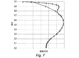
同様に、図6および図7は、スタッキングラインの形状の変化がこの場合はスタッキングラインの高さの最後の30パーセントにわたって生じている、本発明の第二の実施形態を示す。この第二の実施形態において、スタッキングラインの軸方向変形は曲率が1回しか変化しておらず、この変化は最後の30パーセントのうちの最初の25パーセントにわたって先行技術よりも突出しており、最後の5%では反転して、先行技術のスタッキングラインに向かって戻っている。この部分の接線方向変形は、第一の実施形態と同じ曲率の二重変化を有する。 Similarly, FIGS. 6 and 7 illustrate a second embodiment of the present invention in which the change in stacking line shape has occurred over the last 30 percent of the stacking line height in this case. In this second embodiment, the axial deformation of the stacking line has changed in curvature only once, and this change is more prominent than the prior art over the first 25 percent of the last 30 percent. 5% of the turn is reversed and back towards the prior art stacking line. The tangential deformation of this part has the same double curvature change as in the first embodiment.
いずれの実施形態においても、図5および図7に示されたように、スタッキングラインの接線方向変形はブレードの先端に近づくにつれて非常にわかりやすく平坦化していること、および先端におけるこの線との接線は、ターボ機械が回っているときにブレード端において翼弦が描く円筒形と接する平面に含まれるようになることが、わかるだろう。第一の実施形態におけるこのスタッキングラインの軸方向変形にも、同じことが当てはまる(図4参照)。 In either embodiment, as shown in FIGS. 5 and 7, the tangential deformation of the stacking line is very clearly flattened as it approaches the tip of the blade, and tangent to this line at the tip. Will be included in the plane that contacts the cylindrical shape drawn by the chord at the blade end when the turbomachine is turning. The same applies to the axial deformation of this stacking line in the first embodiment (see FIG. 4).
図8は、従来の方法で生じる段と比較したときの、本発明による圧縮段において三次元ナビエストークス計算を用いて得られた性能の改善を示す。2つの曲線は、先行技術の段(下の曲線)および本発明による段(上の曲線)について、等回転速度で得られた点を示す。横軸は、増分あたり0.5kg/sの単位で、段を通過する空気の流量の変化を表し、縦軸は、増分あたり0.1ポイントのスケールで、様々なテスト点で得られた効率を示す。左端の点は、この段の急上昇する線上に位置する点を表し、右端の点は、段の作動線上に位置する点を表し、これは演繹的に圧縮機の設計に採用される。2つの間で、段は最大効率点と称される点を通過するが、これは圧縮機全体の作動線を位置決めするときに目標とされる点である。 FIG. 8 shows the performance improvement obtained using the 3D Navier Stokes calculation in the compression stage according to the invention when compared to the stage occurring in the conventional method. The two curves show the points obtained at the same rotational speed for the prior art stage (lower curve) and the stage according to the invention (upper curve). The horizontal axis represents the change in air flow rate through the stage in units of 0.5 kg / s per increment, and the vertical axis represents the efficiency obtained at various test points on a scale of 0.1 points per increment. Indicates. The leftmost point represents the point located on the steeply rising line of this stage, and the rightmost point represents the point located on the operating line of the stage, which is a priori adopted in the compressor design. Between the two, the stage passes through a point called the maximum efficiency point, which is the point targeted when positioning the operating line of the entire compressor.
本発明による修正ブレードは、ナビエストークス方程式を解けるようにする三次元計算コードを用いて、航空力学的な観点から評価された。得られた結果は、両方の実施形態について、以下のように、圧縮機の効率は、0から100ポイントのスケールで、任意の圧力増加によって流体に実際に適用される仕事と、同じ圧力増加のために供給されなければならない理想的な仕事(等エントロピーの転換)の比率として、設計され得る。すなわち、
−その翼の高さの最後の10パーセントにわたって修正されたブレードについて、平均的に、各段で、圧縮機作動線において先行技術に対して0.15ポイントの効率の増加が見られた(流量の関数として得られる圧力の比率を示す図)。上昇線上で、達成された改善は、平均的に、先行技術に対しておよそ0.30である。上昇の境界線上でのこの改善は、空気ストリームに対するブレードの迎え角を変更することによって作動線を上昇線に近づけることによって、作動線上の効率の改善に変換されてもよい。したがって、本発明によるブレード配列の寄与は、先行技術のブレード配列に対するかなりの改善を示している。
−その高さの最後の30パーセントにわたって修正されたブレードは、実質的に同一の結果をもたらす。
−対照的に、最後の30パーセント超における高さにわたってブレードを修正することでは、目立った付加的な改善は提供されない。この理由は、その先端からのブレードの起伏の距離が大きいことである可能性があり、するとこれらの起伏がブレード端間隙渦に対して及ぼす影響は、無視できなくなる。
The modified blade according to the present invention was evaluated from an aerodynamic point of view using a three-dimensional calculation code that enables the Naviestokes equation to be solved. The results obtained are that, for both embodiments, the compressor efficiency is the same pressure increase as the work actually applied to the fluid by any pressure increase, on a scale of 0 to 100 points, as follows: It can be designed as a ratio of ideal work (isentropic conversion) that must be supplied for. That is,
-On average, for each blade modified over the last 10 percent of its blade height, there was a 0.15 point increase in efficiency in the compressor operating line over the prior art (flow rate) The pressure ratio obtained as a function of. On the rising line, the improvement achieved is on average approximately 0.30 over the prior art. This improvement on the rising boundary may be translated into an improvement in efficiency on the operating line by bringing the operating line closer to the rising line by changing the angle of attack of the blade relative to the air stream. Thus, the blade arrangement contribution according to the present invention represents a considerable improvement over the prior art blade arrangement.
-A blade modified over the last 30 percent of its height yields substantially the same results.
-In contrast, modifying the blade over the height above the last 30 percent does not provide a noticeable additional improvement. The reason for this may be that the undulation distance of the blade from its tip is large, and the influence of these undulations on the blade end gap vortex is not negligible.
本発明は圧縮機ブレードに関連して記載されてきた。先行技術において、ブレード端間隙渦の制御における同じ問題に悩まされてきたタービンブレードでも、同様の改善が得られるだろう。 The present invention has been described in connection with a compressor blade. Similar improvements would be obtained in the prior art for turbine blades that have suffered from the same problems in blade edge clearance vortex control.
Claims (8)
ブレード根元から半径方向に延在する1つの平面上への翼の前記スタッキングラインの投影は、その曲率の方向の少なくとも1つの軸方向転換を含み、この転換は翼の高さの最後の30パーセント以内に位置し、投影面はブレードの翼弦に対して実質的に平行に配向されていることを特徴とする、ブレード。 A turbomachine blade, whose wings are radially between the blade root and tip, axially between the leading edge (2) and trailing edge (3), and suctioned with the pressure surface (4) Extending in a tangential direction with respect to the surface (5), the profile of the blade is a series of blade cross-sectional shapes stacked on each other along a line known as a stacking line connecting all centroids of the cross-section Consisting of basic profiles
Projection of the stacking line of a wing onto a plane extending radially from the blade root includes at least one axial turn in the direction of its curvature, this turn being the last 30 percent of the wing height. A blade, characterized in that it is located within and the projection plane is oriented substantially parallel to the chord of the blade.
Applications Claiming Priority (3)
| Application Number | Priority Date | Filing Date | Title |
|---|---|---|---|
| FR1060538A FR2969230B1 (en) | 2010-12-15 | 2010-12-15 | COMPRESSOR BLADE WITH IMPROVED STACKING LAW |
| FR1060538 | 2010-12-15 | ||
| PCT/FR2011/053000 WO2012080669A1 (en) | 2010-12-15 | 2011-12-15 | Turbine engine blade having improved stacking law |
Publications (2)
| Publication Number | Publication Date |
|---|---|
| JP2013545936A JP2013545936A (en) | 2013-12-26 |
| JP5988994B2 true JP5988994B2 (en) | 2016-09-07 |
Family
ID=44310935
Family Applications (1)
| Application Number | Title | Priority Date | Filing Date |
|---|---|---|---|
| JP2013543865A Active JP5988994B2 (en) | 2010-12-15 | 2011-12-15 | Turbine engine blades with improved stacking rules |
Country Status (9)
| Country | Link |
|---|---|
| US (1) | US9650896B2 (en) |
| EP (1) | EP2652336B1 (en) |
| JP (1) | JP5988994B2 (en) |
| CN (1) | CN103261700B (en) |
| BR (1) | BR112013013569B8 (en) |
| CA (1) | CA2820030C (en) |
| FR (1) | FR2969230B1 (en) |
| RU (1) | RU2603204C2 (en) |
| WO (1) | WO2012080669A1 (en) |
Families Citing this family (44)
| Publication number | Priority date | Publication date | Assignee | Title |
|---|---|---|---|---|
| FR2983234B1 (en) | 2011-11-29 | 2014-01-17 | Snecma | AUBE FOR TURBOMACHINE MONOBLOC AUBING DISK |
| FR2993323B1 (en) * | 2012-07-12 | 2014-08-15 | Snecma | TURBOMACHINE DAWN HAVING A PROFIL CONFIGURED TO OBTAIN IMPROVED AERODYNAMIC AND MECHANICAL PROPERTIES |
| FR2999151B1 (en) * | 2012-12-07 | 2017-01-27 | Snecma | PROPELLER BLADE FOR TURBOMACHINE |
| FR3003598B1 (en) * | 2013-03-20 | 2018-04-06 | Safran Aircraft Engines | DAWN AND ANGEL OF DIEDRE D'AUBE |
| US10233758B2 (en) | 2013-10-08 | 2019-03-19 | United Technologies Corporation | Detuning trailing edge compound lean contour |
| EP3108115B8 (en) | 2014-02-19 | 2023-11-08 | RTX Corporation | Turbofan engine with geared architecture and lpc blades |
| US9140127B2 (en) | 2014-02-19 | 2015-09-22 | United Technologies Corporation | Gas turbine engine airfoil |
| WO2015126449A1 (en) | 2014-02-19 | 2015-08-27 | United Technologies Corporation | Gas turbine engine airfoil |
| WO2015126824A1 (en) | 2014-02-19 | 2015-08-27 | United Technologies Corporation | Gas turbine engine airfoil |
| WO2015175044A2 (en) | 2014-02-19 | 2015-11-19 | United Technologies Corporation | Gas turbine engine airfoil |
| US9163517B2 (en) | 2014-02-19 | 2015-10-20 | United Technologies Corporation | Gas turbine engine airfoil |
| WO2015126451A1 (en) | 2014-02-19 | 2015-08-27 | United Technologies Corporation | Gas turbine engine airfoil |
| EP3108100B1 (en) | 2014-02-19 | 2021-04-14 | Raytheon Technologies Corporation | Gas turbine engine fan blade |
| US10557477B2 (en) | 2014-02-19 | 2020-02-11 | United Technologies Corporation | Gas turbine engine airfoil |
| WO2015126454A1 (en) | 2014-02-19 | 2015-08-27 | United Technologies Corporation | Gas turbine engine airfoil |
| US10465702B2 (en) | 2014-02-19 | 2019-11-05 | United Technologies Corporation | Gas turbine engine airfoil |
| EP3108120B1 (en) | 2014-02-19 | 2021-03-31 | Raytheon Technologies Corporation | Gas turbine engine having a geared architecture and a specific fixed airfoil structure |
| WO2015126774A1 (en) | 2014-02-19 | 2015-08-27 | United Technologies Corporation | Gas turbine engine airfoil |
| EP3108112B1 (en) * | 2014-02-19 | 2023-10-11 | Raytheon Technologies Corporation | Turbofan engine with geared architecture and lpc airfoils |
| EP3108119B1 (en) | 2014-02-19 | 2023-10-04 | RTX Corporation | Turbofan engine with geared architecture and lpc blade airfoils |
| US10422226B2 (en) | 2014-02-19 | 2019-09-24 | United Technologies Corporation | Gas turbine engine airfoil |
| EP3108118B1 (en) | 2014-02-19 | 2019-09-18 | United Technologies Corporation | Gas turbine engine airfoil |
| EP3108123B1 (en) | 2014-02-19 | 2023-10-04 | Raytheon Technologies Corporation | Turbofan engine with geared architecture and lpc airfoils |
| US9567858B2 (en) | 2014-02-19 | 2017-02-14 | United Technologies Corporation | Gas turbine engine airfoil |
| EP3108121B1 (en) | 2014-02-19 | 2023-09-06 | Raytheon Technologies Corporation | Turbofan engine with geared architecture and lpc airfoils |
| US10385866B2 (en) | 2014-02-19 | 2019-08-20 | United Technologies Corporation | Gas turbine engine airfoil |
| EP3575551B1 (en) | 2014-02-19 | 2021-10-27 | Raytheon Technologies Corporation | Gas turbine engine airfoil |
| US10584715B2 (en) | 2014-02-19 | 2020-03-10 | United Technologies Corporation | Gas turbine engine airfoil |
| US9845684B2 (en) * | 2014-11-25 | 2017-12-19 | Pratt & Whitney Canada Corp. | Airfoil with stepped spanwise thickness distribution |
| FR3040071B1 (en) * | 2015-08-11 | 2020-03-27 | Safran Aircraft Engines | TURBOMACHINE ROTOR DAWN |
| ES2717801T3 (en) * | 2015-10-26 | 2019-06-25 | MTU Aero Engines AG | Mobile praise |
| FR3043428B1 (en) * | 2015-11-10 | 2020-05-29 | Safran Aircraft Engines | TURBOMACHINE RECTIFIER DAWN |
| GB2544735B (en) * | 2015-11-23 | 2018-02-07 | Rolls Royce Plc | Vanes of a gas turbine engine |
| CN106351872A (en) * | 2016-09-12 | 2017-01-25 | 深圳友铂科技有限公司 | Compressor rotor blade meeting both pneumatic and strength requirements |
| FR3062431B1 (en) * | 2017-01-27 | 2021-01-01 | Safran Helicopter Engines | WHEEL BLADE FOR TURBOMACHINE, INCLUDING A VANE AT ITS TOP AND ATTACKING EDGE |
| FR3062432B1 (en) * | 2017-01-30 | 2020-11-13 | Safran Aircraft Engines | IMPROVED AUBES ATTACK EDGE PROFILE |
| CN106931512B (en) * | 2017-03-02 | 2019-08-20 | 南京航空航天大学 | Air-conditioning omnidirectional air outlet indoor unit and its outlet air method |
| WO2019119379A1 (en) * | 2017-12-21 | 2019-06-27 | 深圳市大疆创新科技有限公司 | Propeller, power assembly, and unmanned aerial vehicle |
| EP3760875B1 (en) * | 2018-06-22 | 2022-06-15 | Mitsubishi Heavy Industries Engine & Turbocharger, Ltd. | Rotor and centrifugal compression machine provided with said rotor |
| BE1026579B1 (en) * | 2018-08-31 | 2020-03-30 | Safran Aero Boosters Sa | PROTUBERANCE VANE FOR TURBOMACHINE COMPRESSOR |
| WO2020161943A1 (en) * | 2019-02-07 | 2020-08-13 | 株式会社Ihi | Method for designing blade for axial flow type fan, compressor and turbine, and blade obtained by means of said design |
| BE1028118B1 (en) | 2020-03-02 | 2021-09-27 | Safran Aero Boosters | BLADE FOR TURBOMACHINE COMPRESSOR |
| BE1028234B1 (en) | 2020-04-24 | 2021-12-03 | Safran Aero Boosters | BLADE FOR TURBOMACHINE COMPRESSOR |
| CN115717552A (en) * | 2022-11-08 | 2023-02-28 | 东方电气集团东方汽轮机有限公司 | Turbine moving blade |
Family Cites Families (23)
| Publication number | Priority date | Publication date | Assignee | Title |
|---|---|---|---|---|
| US1469973A (en) * | 1922-10-06 | 1923-10-09 | Westinghouse Electric & Mfg Co | Turbine blading |
| US2714499A (en) * | 1952-10-02 | 1955-08-02 | Gen Electric | Blading for turbomachines |
| DE9013099U1 (en) * | 1990-09-14 | 1991-11-07 | Moser, Josef, 8058 Pretzen | rotor |
| US5525038A (en) * | 1994-11-04 | 1996-06-11 | United Technologies Corporation | Rotor airfoils to control tip leakage flows |
| JPH08312303A (en) * | 1995-05-18 | 1996-11-26 | Mitsubishi Heavy Ind Ltd | Curved stacking method for axial compressor |
| US6071077A (en) | 1996-04-09 | 2000-06-06 | Rolls-Royce Plc | Swept fan blade |
| JPH10103002A (en) * | 1996-09-30 | 1998-04-21 | Toshiba Corp | Blade for axial flow fluid machine |
| DE19812624A1 (en) * | 1998-03-23 | 1999-09-30 | Bmw Rolls Royce Gmbh | Rotor blade of an axial flow machine |
| US6331100B1 (en) * | 1999-12-06 | 2001-12-18 | General Electric Company | Doubled bowed compressor airfoil |
| US6341942B1 (en) * | 1999-12-18 | 2002-01-29 | General Electric Company | Rotator member and method |
| JP3979388B2 (en) | 2002-02-28 | 2007-09-19 | ダイキン工業株式会社 | Blower |
| FR2851798B1 (en) * | 2003-02-27 | 2005-04-29 | Snecma Moteurs | TURBOREACTOR TURBINE BOW |
| DE102004011607B4 (en) * | 2004-03-10 | 2016-11-24 | MTU Aero Engines AG | Compressor of a gas turbine and gas turbine |
| GB0701866D0 (en) * | 2007-01-31 | 2007-03-14 | Rolls Royce Plc | Tone noise reduction in turbomachines |
| EP1953344B1 (en) * | 2007-02-05 | 2012-04-11 | Siemens Aktiengesellschaft | Turbine blade |
| US8083487B2 (en) * | 2007-07-09 | 2011-12-27 | General Electric Company | Rotary airfoils and method for fabricating same |
| RU2354854C1 (en) * | 2007-12-20 | 2009-05-10 | Федеральное государственное унитарное предприятие "Центральный институт авиационного моторостроения имени П.И. Баранова" | Axial blower or compressor high-rpm impeller |
| US8147207B2 (en) * | 2008-09-04 | 2012-04-03 | Siemens Energy, Inc. | Compressor blade having a ratio of leading edge sweep to leading edge dihedral in a range of 1:1 to 3:1 along the radially outer portion |
| US8480372B2 (en) * | 2008-11-06 | 2013-07-09 | General Electric Company | System and method for reducing bucket tip losses |
| US8167567B2 (en) * | 2008-12-17 | 2012-05-01 | United Technologies Corporation | Gas turbine engine airfoil |
| FR2940374B1 (en) | 2008-12-23 | 2015-02-20 | Snecma | COMPRESSOR HOUSING WITH OPTIMIZED CAVITIES. |
| JP4923073B2 (en) * | 2009-02-25 | 2012-04-25 | 株式会社日立製作所 | Transonic wing |
| JP5461029B2 (en) * | 2009-02-27 | 2014-04-02 | 三菱重工業株式会社 | Gas turbine blade |
-
2010
- 2010-12-15 FR FR1060538A patent/FR2969230B1/en active Active
-
2011
- 2011-12-15 CN CN201180059503.0A patent/CN103261700B/en active Active
- 2011-12-15 US US13/993,079 patent/US9650896B2/en active Active
- 2011-12-15 EP EP11817347.5A patent/EP2652336B1/en active Active
- 2011-12-15 WO PCT/FR2011/053000 patent/WO2012080669A1/en active Application Filing
- 2011-12-15 BR BR112013013569A patent/BR112013013569B8/en active IP Right Grant
- 2011-12-15 CA CA2820030A patent/CA2820030C/en active Active
- 2011-12-15 JP JP2013543865A patent/JP5988994B2/en active Active
- 2011-12-15 RU RU2013126514/06A patent/RU2603204C2/en active
Also Published As
| Publication number | Publication date |
|---|---|
| CN103261700B (en) | 2016-06-15 |
| FR2969230B1 (en) | 2014-11-21 |
| US9650896B2 (en) | 2017-05-16 |
| WO2012080669A1 (en) | 2012-06-21 |
| BR112013013569B8 (en) | 2020-12-08 |
| RU2603204C2 (en) | 2016-11-27 |
| BR112013013569B1 (en) | 2020-09-15 |
| JP2013545936A (en) | 2013-12-26 |
| EP2652336A1 (en) | 2013-10-23 |
| CA2820030C (en) | 2020-07-07 |
| RU2013126514A (en) | 2015-01-20 |
| CA2820030A1 (en) | 2012-06-21 |
| US20130266451A1 (en) | 2013-10-10 |
| BR112013013569A2 (en) | 2016-10-11 |
| CN103261700A (en) | 2013-08-21 |
| EP2652336B1 (en) | 2019-05-01 |
| FR2969230A1 (en) | 2012-06-22 |
Similar Documents
| Publication | Publication Date | Title |
|---|---|---|
| JP5988994B2 (en) | Turbine engine blades with improved stacking rules | |
| EP2820279B1 (en) | Turbomachine blade | |
| JP6034860B2 (en) | Turbomachine element | |
| CA2849651C (en) | Axial turbomachine stator with ailerons at the blade roots | |
| JP4923073B2 (en) | Transonic wing | |
| JP5410014B2 (en) | The latest booster stator vane | |
| JP2015183691A (en) | gas turbine blade | |
| JP6367917B2 (en) | Radial or mixed flow compressor diffuser with vanes | |
| US20090041576A1 (en) | Fluid flow machine featuring an annulus duct wall recess | |
| US20170218773A1 (en) | Blade cascade and turbomachine | |
| JPWO2012053024A1 (en) | Transonic wing | |
| JP2011528081A (en) | Axial flow turbomachine with low gap loss | |
| JP5351941B2 (en) | Centrifugal compressor, its impeller, its operating method, and impeller design method | |
| US9377029B2 (en) | Blade of a turbomachine | |
| US20140248154A1 (en) | Blade of a row of rotor blades or stator blades for use in a turbomachine | |
| US11047238B2 (en) | Leading edge profile of vanes | |
| US20180298912A1 (en) | Compressor blades and/or vanes | |
| CA2856264A1 (en) | Blade for axial compressor rotor | |
| US10655471B2 (en) | Turbine and gas turbine | |
| EP2369133B1 (en) | Airfoil for a turbo-machine | |
| JP7025444B2 (en) | Reinforced axial diffuser | |
| JP2010534792A (en) | Steam turbine stage | |
| JP2015121221A (en) | Rotary machine blade having asymmetric part-span shroud and method of making the same | |
| WO2016075955A1 (en) | Impeller and centrifugal compressor | |
| RU2794951C2 (en) | Gas turbine engine blade with maximum thickness rule with high flutter strength |
Legal Events
| Date | Code | Title | Description |
|---|---|---|---|
| A521 | Request for written amendment filed |
Free format text: JAPANESE INTERMEDIATE CODE: A523 Effective date: 20130814 |
|
| A621 | Written request for application examination |
Free format text: JAPANESE INTERMEDIATE CODE: A621 Effective date: 20141210 |
|
| A977 | Report on retrieval |
Free format text: JAPANESE INTERMEDIATE CODE: A971007 Effective date: 20151016 |
|
| A131 | Notification of reasons for refusal |
Free format text: JAPANESE INTERMEDIATE CODE: A131 Effective date: 20151104 |
|
| TRDD | Decision of grant or rejection written | ||
| A01 | Written decision to grant a patent or to grant a registration (utility model) |
Free format text: JAPANESE INTERMEDIATE CODE: A01 Effective date: 20160726 |
|
| A61 | First payment of annual fees (during grant procedure) |
Free format text: JAPANESE INTERMEDIATE CODE: A61 Effective date: 20160809 |
|
| R150 | Certificate of patent or registration of utility model |
Ref document number: 5988994 Country of ref document: JP Free format text: JAPANESE INTERMEDIATE CODE: R150 |
|
| R250 | Receipt of annual fees |
Free format text: JAPANESE INTERMEDIATE CODE: R250 |
|
| R250 | Receipt of annual fees |
Free format text: JAPANESE INTERMEDIATE CODE: R250 |
|
| R250 | Receipt of annual fees |
Free format text: JAPANESE INTERMEDIATE CODE: R250 |
|
| R250 | Receipt of annual fees |
Free format text: JAPANESE INTERMEDIATE CODE: R250 |
|
| R250 | Receipt of annual fees |
Free format text: JAPANESE INTERMEDIATE CODE: R250 |
|
| R250 | Receipt of annual fees |
Free format text: JAPANESE INTERMEDIATE CODE: R250 |