JP5988992B2 - Tubular separator as an ultra-precision separator to reduce fine dust emissions and avoid stack rain - Google Patents
Tubular separator as an ultra-precision separator to reduce fine dust emissions and avoid stack rain Download PDFInfo
- Publication number
- JP5988992B2 JP5988992B2 JP2013543618A JP2013543618A JP5988992B2 JP 5988992 B2 JP5988992 B2 JP 5988992B2 JP 2013543618 A JP2013543618 A JP 2013543618A JP 2013543618 A JP2013543618 A JP 2013543618A JP 5988992 B2 JP5988992 B2 JP 5988992B2
- Authority
- JP
- Japan
- Prior art keywords
- separator
- separation
- separation system
- droplets
- droplet
- Prior art date
- Legal status (The legal status is an assumption and is not a legal conclusion. Google has not performed a legal analysis and makes no representation as to the accuracy of the status listed.)
- Active
Links
Images


Classifications
-
- B—PERFORMING OPERATIONS; TRANSPORTING
- B01—PHYSICAL OR CHEMICAL PROCESSES OR APPARATUS IN GENERAL
- B01D—SEPARATION
- B01D53/00—Separation of gases or vapours; Recovering vapours of volatile solvents from gases; Chemical or biological purification of waste gases, e.g. engine exhaust gases, smoke, fumes, flue gases, aerosols
- B01D53/34—Chemical or biological purification of waste gases
- B01D53/46—Removing components of defined structure
- B01D53/48—Sulfur compounds
- B01D53/50—Sulfur oxides
-
- B—PERFORMING OPERATIONS; TRANSPORTING
- B01—PHYSICAL OR CHEMICAL PROCESSES OR APPARATUS IN GENERAL
- B01D—SEPARATION
- B01D45/00—Separating dispersed particles from gases or vapours by gravity, inertia, or centrifugal forces
- B01D45/04—Separating dispersed particles from gases or vapours by gravity, inertia, or centrifugal forces by utilising inertia
- B01D45/08—Separating dispersed particles from gases or vapours by gravity, inertia, or centrifugal forces by utilising inertia by impingement against baffle separators
-
- B—PERFORMING OPERATIONS; TRANSPORTING
- B01—PHYSICAL OR CHEMICAL PROCESSES OR APPARATUS IN GENERAL
- B01D—SEPARATION
- B01D45/00—Separating dispersed particles from gases or vapours by gravity, inertia, or centrifugal forces
- B01D45/04—Separating dispersed particles from gases or vapours by gravity, inertia, or centrifugal forces by utilising inertia
- B01D45/06—Separating dispersed particles from gases or vapours by gravity, inertia, or centrifugal forces by utilising inertia by reversal of direction of flow
-
- B—PERFORMING OPERATIONS; TRANSPORTING
- B01—PHYSICAL OR CHEMICAL PROCESSES OR APPARATUS IN GENERAL
- B01D—SEPARATION
- B01D45/00—Separating dispersed particles from gases or vapours by gravity, inertia, or centrifugal forces
- B01D45/12—Separating dispersed particles from gases or vapours by gravity, inertia, or centrifugal forces by centrifugal forces
-
- B—PERFORMING OPERATIONS; TRANSPORTING
- B01—PHYSICAL OR CHEMICAL PROCESSES OR APPARATUS IN GENERAL
- B01D—SEPARATION
- B01D46/00—Filters or filtering processes specially modified for separating dispersed particles from gases or vapours
- B01D46/66—Regeneration of the filtering material or filter elements inside the filter
- B01D46/70—Regeneration of the filtering material or filter elements inside the filter by acting counter-currently on the filtering surface, e.g. by flushing on the non-cake side of the filter
- B01D46/71—Regeneration of the filtering material or filter elements inside the filter by acting counter-currently on the filtering surface, e.g. by flushing on the non-cake side of the filter with pressurised gas, e.g. pulsed air
-
- B—PERFORMING OPERATIONS; TRANSPORTING
- B01—PHYSICAL OR CHEMICAL PROCESSES OR APPARATUS IN GENERAL
- B01D—SEPARATION
- B01D50/00—Combinations of methods or devices for separating particles from gases or vapours
- B01D50/20—Combinations of devices covered by groups B01D45/00 and B01D46/00
-
- B—PERFORMING OPERATIONS; TRANSPORTING
- B01—PHYSICAL OR CHEMICAL PROCESSES OR APPARATUS IN GENERAL
- B01D—SEPARATION
- B01D53/00—Separation of gases or vapours; Recovering vapours of volatile solvents from gases; Chemical or biological purification of waste gases, e.g. engine exhaust gases, smoke, fumes, flue gases, aerosols
- B01D53/34—Chemical or biological purification of waste gases
- B01D53/46—Removing components of defined structure
- B01D53/48—Sulfur compounds
-
- B—PERFORMING OPERATIONS; TRANSPORTING
- B01—PHYSICAL OR CHEMICAL PROCESSES OR APPARATUS IN GENERAL
- B01D—SEPARATION
- B01D53/00—Separation of gases or vapours; Recovering vapours of volatile solvents from gases; Chemical or biological purification of waste gases, e.g. engine exhaust gases, smoke, fumes, flue gases, aerosols
- B01D53/34—Chemical or biological purification of waste gases
- B01D53/74—General processes for purification of waste gases; Apparatus or devices specially adapted therefor
- B01D53/77—Liquid phase processes
- B01D53/78—Liquid phase processes with gas-liquid contact
-
- B—PERFORMING OPERATIONS; TRANSPORTING
- B01—PHYSICAL OR CHEMICAL PROCESSES OR APPARATUS IN GENERAL
- B01D—SEPARATION
- B01D2251/00—Reactants
- B01D2251/40—Alkaline earth metal or magnesium compounds
- B01D2251/404—Alkaline earth metal or magnesium compounds of calcium
-
- B—PERFORMING OPERATIONS; TRANSPORTING
- B01—PHYSICAL OR CHEMICAL PROCESSES OR APPARATUS IN GENERAL
- B01D—SEPARATION
- B01D2257/00—Components to be removed
- B01D2257/30—Sulfur compounds
- B01D2257/302—Sulfur oxides
-
- B—PERFORMING OPERATIONS; TRANSPORTING
- B01—PHYSICAL OR CHEMICAL PROCESSES OR APPARATUS IN GENERAL
- B01D—SEPARATION
- B01D53/00—Separation of gases or vapours; Recovering vapours of volatile solvents from gases; Chemical or biological purification of waste gases, e.g. engine exhaust gases, smoke, fumes, flue gases, aerosols
- B01D53/34—Chemical or biological purification of waste gases
- B01D53/46—Removing components of defined structure
- B01D53/48—Sulfur compounds
- B01D53/50—Sulfur oxides
- B01D53/501—Sulfur oxides by treating the gases with a solution or a suspension of an alkali or earth-alkali or ammonium compound
- B01D53/504—Sulfur oxides by treating the gases with a solution or a suspension of an alkali or earth-alkali or ammonium compound characterised by a specific device
-
- F—MECHANICAL ENGINEERING; LIGHTING; HEATING; WEAPONS; BLASTING
- F01—MACHINES OR ENGINES IN GENERAL; ENGINE PLANTS IN GENERAL; STEAM ENGINES
- F01M—LUBRICATING OF MACHINES OR ENGINES IN GENERAL; LUBRICATING INTERNAL COMBUSTION ENGINES; CRANKCASE VENTILATING
- F01M13/00—Crankcase ventilating or breathing
- F01M13/04—Crankcase ventilating or breathing having means for purifying air before leaving crankcase, e.g. removing oil
Landscapes
- Chemical & Material Sciences (AREA)
- Chemical Kinetics & Catalysis (AREA)
- Engineering & Computer Science (AREA)
- Environmental & Geological Engineering (AREA)
- Health & Medical Sciences (AREA)
- Biomedical Technology (AREA)
- Analytical Chemistry (AREA)
- General Chemical & Material Sciences (AREA)
- Oil, Petroleum & Natural Gas (AREA)
- Treating Waste Gases (AREA)
- Separating Particles In Gases By Inertia (AREA)
- Gas Separation By Absorption (AREA)
Description
本発明は、発電所の煙道ガス脱硫部において使用するための液滴分離システムに関する。この分離器コンセプトは、一方ではヨーロッパや米国における新しいエミッション規制の要求に応えて、当該規制において要求された分離能力を提供することが望まれる。他方において、このコンセプトはスタックレイン(湿式煙突からの著しい液滴放出)の既知の問題を克服することが望まれる。さらに、この分離器コンセプトは、液滴分離器に(煙道ガス流れ方向で)続くコンポーネントの汚染を最小限に抑えることが望まれる。 The present invention relates to a droplet separation system for use in a flue gas desulfurization section of a power plant. On the one hand, this separator concept is desired to meet the requirements of new emission regulations in Europe and the United States and provide the separation capacity required in such regulations. On the other hand, this concept is desired to overcome the known problem of stuck rain (significant droplet ejection from a wet chimney). Further, this separator concept is desired to minimize contamination of the components that follow the droplet separator (in the flue gas flow direction).
化石燃料を燃焼させる火力発電所からの煙道ガスは、主として、湿式洗浄法により脱硫される。硫黄含有の煙道ガスには、石灰乳(懸濁溶液)が噴霧され、煙道ガス中に存在するSO2はこの懸濁溶液のスプレイ滴に結合され、次いで硫酸カルシウムの二水和物(石膏)に変換される。これらのスプレイ滴のうちの小さなスプレイ滴は、ガス流によって一緒に案内される。 Flue gas from a thermal power plant that burns fossil fuel is mainly desulfurized by a wet cleaning method. The sulfur-containing flue gas is sprayed with lime milk (suspension solution), the SO 2 present in the flue gas is bound to the spray droplets of this suspension solution, and then the calcium sulfate dihydrate ( Gypsum). Small spray droplets of these spray droplets are guided together by the gas flow.
液滴分離システムの役目は、煙道ガス流中に同伴されてきたこれらの液滴を捕集して、洗浄循環路内に戻すことである。さもないと、後置された、つまり下流側に配置されたコンポーネント(熱交換器、煙道ガス通路、湿式ブロワ、煙突等)において焼付きが生じ、ひいては腐食や圧力損失増大が生じる。その結果は、発電所の出力減少(圧力損失増大は、高められた電流自己消費および場合によっては発電量の減少の原因となる)および保守コスト(腐食個所の補修および焼付きを除去するためのクリーニングコスト)である。 The role of the droplet separation system is to collect these droplets entrained in the flue gas stream and return them to the cleaning circuit. Otherwise, seizure occurs in the components (heat exchangers, flue gas passages, wet blowers, chimneys, etc.) disposed downstream, that is, downstream, which in turn causes corrosion and increased pressure loss. The result is reduced power plant output (increased pressure loss causes increased current self-consumption and, in some cases, reduced power generation) and maintenance costs (to eliminate repairs and seizure of corrosion sites). Cleaning cost).
ヨーロッパおよび米国において適用または計画された新しいエミッション規制は、さらに煙道ガス中の固形物含量の著しい低減を規定している(微細ダスト低減)。これらの新規の限界値は、煙道ガス脱硫における分離の抜本的な改善を強要している。ヨーロッパの幾つかの国々や地域は最近、微細ダストおよび固形物含量を3〜6mg/Nm3にまで低減させることを要求している。 New emission regulations applied or planned in Europe and the United States further define a significant reduction in solids content in flue gas (fine dust reduction). These new limits force a radical improvement in separation in flue gas desulfurization. Several countries and regions in Europe have recently required to reduce the fine dust and solids content to 3-6 mg / Nm 3 .
さらに、米国および最近ではヨーロッパにおいても、多数の発電所が、いわゆる「湿式煙突(ウエットスタック)」を装備している。煙道ガスは再加熱なしに飽和されてスタックもしくは煙突内に導入され、煙突を通る途中で冷却されることに基づき液体を凝縮させ、そして「湿った」煙突を生ぜしめる。このような湿式煙突の多くに認められる問題は、大量の液滴が煙突から放出されることである。液滴は煙突のすぐ近くに降雨し、そして時には少し離れた場所にも降雨する。発電所の設備は汚染され、近くに設置された別の装置や建造物も汚染され、さらに人間や動物も煩わされる。これらの液滴はどちらかと云えば酸性であるので、この煙突雨、すなわちスタックレインは、当該設備の腐食や損傷を招き、自動車の塗装は破壊され、土壌は酸性化され、建物ファサードや屋根は腐食により損傷されることなどが起こる。 In addition, many power plants in the United States and more recently in Europe are equipped with so-called “wet chimneys”. The flue gas saturates without reheating and is introduced into the stack or chimney, condensing the liquid based on cooling on the way through the chimney and creating a “wet” chimney. A problem observed in many of such wet chimneys is that a large number of droplets are ejected from the chimney. The droplets rain in the immediate vicinity of the chimney, and sometimes also at some distance. Power plant equipment is polluted, nearby equipment and structures are polluted, and humans and animals are bothered. Because these droplets are rather acidic, this chimney rain, or stack rain, can lead to corrosion and damage to the equipment, the car paint is destroyed, the soil is acidified, and the building facade and roof are It can be damaged by corrosion.
スタックレインの被害や、微細ダストエミッションの問題は、伝統的に使用される2段式の液滴分離器(ミストエリミネータ)ではもはや十分ではないことを示している。液滴分離器の背後における残留含量中の固形物(微細ダスト、塩等)の量は、これらの限界値内で許容される値よりも高い。液滴放出(スタックレイン)は、大きな問題であり、近隣住民や環境保護団体との摩擦を生む要因となる。煙道ガス経路における焼付きや閉塞は、コストの原因となり、電流生産量を減少させる。 The damage of stuck rain and the problem of fine dust emissions indicate that traditionally used two-stage droplet separators (mist eliminators) are no longer sufficient. The amount of solids (fine dust, salt, etc.) in the residual content behind the droplet separator is higher than allowed within these limits. Droplet discharge (stack rain) is a major problem and causes friction with neighboring residents and environmental groups. Seizures and blockages in the flue gas path cause costs and reduce current production.
背景技術
煙道ガス脱硫用の最新の液滴分離器は、現在、洗浄器ヘッド上部に、煙道ガス通路内への流出部の手前で取り付けられる。この液滴分離器は、鉛直方向上方へ向かって流れる煙道ガスによって負荷される。この配置構成は、コストならびに運転理由から、最良の配置構成である。
State of the art Modern state-of-the-art droplet separators for flue gas desulfurization are currently mounted on top of the scrubber head, just before the outlet into the flue gas passage. The droplet separator is loaded with flue gas flowing upward in the vertical direction. This arrangement is the best arrangement for cost and operational reasons.
液滴分離システムはこの場合、液滴ならびに乾燥した固形物成分をガス流から分離し、この場合、液滴分離システムは煙道ガス流を変向させる。このときに、液滴および乾燥した固形物は、遠心力にさらされる。液滴および乾燥した固形物は、煙道ガスの軌道に従うことができず、流れ抵抗に衝突して跳ね返る。これらの流れ抵抗が、煙道ガスの変向を生ぜしめる。これにより、液滴はこれらの「跳ね返し体(バッフル体)」において分離され、これによって煙道ガス流から除去される。分離された液体は、次いで重力により再び下方へ向かって洗浄循環路に逆流する。 The droplet separation system in this case separates the droplets as well as the dried solid component from the gas stream, in which case the droplet separation system redirects the flue gas stream. At this time, the droplets and dried solids are subjected to centrifugal force. The droplets and dried solids cannot follow the flue gas trajectory and bounce off the flow resistance. These flow resistances cause the flue gas diversion. Thereby, the droplets are separated in these “bounce bodies” and thereby removed from the flue gas stream. The separated liquid then flows back down into the washing circuit again by gravity.
液滴分離器は慣用的には、複数の曲げられたプレート状の変向体から成るユニットから構成されている。曲げられかつ剛性的に懸吊されたこれらのプレート状の変向体は、複数の通路が形成されて、これらの通路を通って煙道ガスが流れるように構成される。この構成の目的は、一方では煙道ガスの強力な変向を生ぜしめ、他方では流れ抵抗による煙道ガス経路の「遮断」を最小限に抑えることである。これらのバッフル体または変向金属薄板は、一般に「多板(Lamellen)」と呼ばれ、分離器自体は、相応して「多板式分離器(Lamellenabscheider)」と呼ばれる。種々の製造業者の汎用の多板式分離器は、そのジオメトリ(幾何学的形状)、多板間隔および変向部ならびに構造(屋根型、フラット型または水平方向流過型)に基づいてのみ互いに異なっている。これらの多板式分離器は機能の点では基本的に同一である。 A droplet separator is conventionally composed of a unit consisting of a plurality of bent plate-shaped deflectors. The bent and rigidly suspended plate-like deflectors are configured such that a plurality of passages are formed and flue gas flows through the passages. The purpose of this configuration is, on the one hand, to produce a strong turn of the flue gas and on the other hand to minimize the “blocking” of the flue gas path due to flow resistance. These baffles or diverted sheet metal are generally referred to as “Lamellen” and the separator itself is correspondingly called “Lamellenabscheider”. General-purpose multi-plate separators from different manufacturers differ from each other only based on their geometry, multi-plate spacing and turning parts and structure (roof type, flat type or horizontal flow type) ing. These multi-plate separators are basically the same in terms of function.
液滴分離システムは、少なくとも2段式に設計されている。運転経験により、液滴を煙道ガスから確実に除去するためには、1段式の分離システムでは基本的に十分でないことが判っている。しかし、2段式の液滴分離器(粗分離器と精密分離器)も、固形物を有するまだかなりの量の液滴を煙道ガスと共に逃し、しかもこの量は、しばしば環境規制の要求、運転要件および湿式煙突の運転のためには多過ぎる。 The droplet separation system is designed in at least two stages. Operating experience has shown that a single-stage separation system is basically not sufficient to reliably remove droplets from flue gas. However, two-stage droplet separators (coarse and precision separators) also escape a significant amount of droplets with solids along with the flue gas, and this amount is often required by environmental regulations, Too many for operating requirements and wet chimney operation.
それゆえに、最近では多くの液滴分離器が3段式に構成される。このような3段式の配置構成では、実際の分離が、粗分離器と精密分離器とにより実施される。粗分離器は煙道ガスから液滴の質量を取り出し、部分的には90%を著しく上回る分離度を達成する。精密分離器は、一方では煙道ガスからさらに液滴を取り出し、粗分離器の洗浄から液滴を捕集し、なお、粗分離器の多板における液滴の跳ね返りの際に発生し得る二次液滴の大部分をも捕集する(反射液滴)。第3の分離器または「極精密分離器」は、3つの機能を具備している。 Therefore, recently, many droplet separators are configured in a three-stage manner. In such a three-stage arrangement, the actual separation is performed by a coarse separator and a fine separator. The coarse separator takes the mass of the droplets from the flue gas and achieves a degree of separation in part significantly exceeding 90%. The precision separator, on the one hand, removes further droplets from the flue gas, collects the droplets from the cleaning of the coarse separator, and can also occur when the droplets bounce on multiple plates of the coarse separator. It also collects most of the next droplet (reflecting droplet). The third separator or “ultra-precision separator” has three functions.
1.微細液滴
極精密分離器は、粗分離器および精密分離器を通過することのできた超微細液滴を引き続き煙道ガスから濾別する。しかし、この超微細液滴の液体量および固形物量は極めて僅かである。したがって、この極精密分離はあまり重要ではない。
1. Fine droplets The ultrafine separator continues to filter the ultrafine droplets that could pass through the coarse and fine separators from the flue gas. However, the amount of liquid and solid matter of the ultrafine droplets is extremely small. Therefore, this ultra-precise separation is not very important.
2.故障
極精密分離器は、故障に基づき精密分離器を通り抜ける液滴を分離する。このような故障の原因は、通り抜けを招く粗分離器および精密分離器の汚染であるか、または最初の2つの分離器の性能を損なう局所的な速度ピークを生ぜしめる煙道ガス流の著しい不均一分配である。しかし、最新の煙道ガス脱硫設備においては、このような事態はむしろ希である。したがって、このような機能も、やはりあまり重要ではない。
2. Failure The ultra-precision separator separates droplets that pass through the precision separator based on failure. The cause of such a failure is a coarse and fine separator contamination leading to the passage, or a significant fault in the flue gas flow that causes local velocity peaks that impair the performance of the first two separators. Uniform distribution. However, this situation is rather rare in the latest flue gas desulfurization equipment. Therefore, this function is also not very important.
3.精密分離器の洗浄
極精密分離器は、精密分離器の洗浄時にこの精密分離器から引き出される洗浄液を分離する。精密分離器の洗浄が著しい液滴エミッションを生ぜしめることは、多くの測定から知られている。実験室での測定、たとえば発電所における保証測定は、液体量の60〜80%が精密分離器の洗浄中に精密分離器の下流側で放出されるという結果をもたらした。この洗浄滴の分離は、極精密分離器の主機能である。
3. Cleaning the precision separator The ultra-precision separator separates the cleaning liquid drawn from the precision separator when the precision separator is cleaned. It is known from many measurements that the cleaning of precision separators produces significant droplet emissions. Laboratory measurements, such as warranty measurements at power plants, have resulted in 60-80% of the liquid volume being discharged downstream of the precision separator during the precision separator cleaning. This washing droplet separation is the main function of the ultra-precision separator.
微細ダストエミッション/スタックレイン
微細ダストエミッションの問題は、ここ数年の間にかなり注目されており、多くの国では微細ダストエミッションに関する規制が厳格化された。その目的は、もちろん人間の健康の保護である。
Fine Dust Emission / Stack Rain The problem of fine dust emission has received considerable attention over the last few years, and regulations on fine dust emission have been tightened in many countries. The purpose is of course to protect human health.
この議論の第2の理由としては、CO2削減のための計画された設備が挙げられる。多くのCO2分離技術は、煙道ガス中の極めて僅かな微細ダスト含量を要求する。これらの分離技術は、CO2をパッケージおよび充填体の形でかつ結合剤を介して分離する方法である。煙道ガスからの固形物は、分離設備を汚染しかつ閉塞させ、それゆえに故障発生因子となる。 The second reason of this discussion, and the like planned facilities for CO 2 reduction. Many CO 2 separation techniques require very little fine dust content in the flue gas. These separation techniques are methods of separating CO 2 in the form of packages and packings and via a binder. Solids from the flue gas can contaminate and clog the separation equipment and thus become a failure factor.
さらに、湿式煙突からのスタックレインの問題により、微細ダストへの注目が集まっている。スタックもしくは煙突からの酸性雨は、煙突のすぐ周辺の地域における汚染や腐食損害をもたらし、そして近隣住民との相応する摩擦や紛争を招く。 In addition, attention has been focused on fine dust due to the problem of stack rain from wet chimneys. Acid rain from stacks or chimneys causes pollution and corrosion damage in the immediate surroundings of the chimney and causes corresponding friction and conflict with neighboring residents.
液滴分離器は、もちろん関心の中心である。なぜならば、液滴分離器は分離に対して、ひいては微細ダストエミッションの低減に対して責任ある役割を担っているからである。それゆえに、高い微細ダストエミッション、スタックレインおよびCO2分離における問題は、当然、煙道ガス脱硫設備における液滴の「分離不良」に帰因される。 The droplet separator is of course the center of interest. This is because the droplet separator plays a responsible role for separation and thus for reducing fine dust emissions. Therefore, problems in high fine dust emissions, stack rain and CO 2 separation are naturally attributed to the “separation failure” of the droplets in the flue gas desulfurization facility.
スタックレインはこの場合、多くの発電所においては直接的な関心事である。スタックレインは、発電所の従業員、近隣住民および発電所近隣で働く人々にとってはすぐに気づくものであり、不都合な結果(汚染および腐食)も迅速に確認され得る。 Stack rain is in this case a direct concern at many power plants. Stack rain is immediately noticeable to power plant employees, neighbors and people working near the power plant, and adverse consequences (contamination and corrosion) can also be quickly identified.
このスタックレインは、著しい固形物含量(石膏および石灰石)を有する大きな液滴から成っていて、酸性である(軽度の酸含量)。これらの液滴は、鏡面状の表面(自動車)の上ではすぐに認識可能である。急速に開始する腐食は、車両の塗装を腐食させ、庭、建物および設備における被害を招く。 This stack train consists of large droplets with a significant solids content (gypsum and limestone) and is acidic (mild acid content). These droplets are readily recognizable on specular surfaces (automobiles). Rapidly starting corrosion corrodes the vehicle's paint and causes damage to gardens, buildings and equipment.
米国では、スタックレインは既に多くの訴訟や、発電所経営者と、近隣住民、環境保護団体および環境官庁との間での法的な紛争の対象となっている。 In the United States, stackrains are already the subject of many lawsuits and legal disputes between power plant managers, neighborhood residents, environmental groups, and environmental authorities.
すなわち、スタックレインにおける濃度は、純然たる液体容量によっても、液滴の大きさによっても、説明され得る。標準運転(洗浄なし)における液滴分離器をすり抜ける小さな液滴または煙突内での凝縮により生じる小さな液滴は、スタックレインとして目に付かない。なぜならば、このような液滴は通常、地上に到達する前に蒸発してしまうからである。煙突先端部と地上との距離は、このために十分な大きさに設定されている。さらに、洗浄時における液滴の量は、スタックレインが気づかれることを招く。個々の液滴は無視され、気づかれないかもしれない。 That is, the concentration in the stack rain can be explained either by pure liquid volume or by droplet size. Small droplets that slip through the droplet separator in normal operation (without washing) or that are caused by condensation in the chimney are not visible as stack rain. This is because such droplets usually evaporate before reaching the ground. The distance between the chimney tip and the ground is set large enough for this purpose. Further, the amount of droplets during cleaning causes the stack rain to be noticed. Individual droplets are ignored and may not be noticed.
スタックレインの問題は、ヨーロッパの旧式の発電所においては知られていない。なぜならば、再加熱がこの問題を回避したからである。しかし、これらの発電所においては、一見別と思われる問題が繰返し持ち上がった。すなわち、微細ダスト放出である。発電所は煙突における煙道ガス中のダスト含量を測定し、この場合、再三、ダスト放出におけるピークが生じ、このピークが監督官庁との軋轢を招いた。 The problem of stuck rain is not known in older European power plants. This is because reheating avoided this problem. However, at these power plants, problems that seemed otherwise seemed to be raised repeatedly. That is, fine dust emission. The power plant measured the dust content in the flue gas at the chimney, in which case there were repeated peaks in the dust emission, which led to a trap with the supervisory authorities.
この微細ダスト問題は、米国の旧式の発電所におけるスタックレインまたは現在ではヨーロッパの最新の発電所におけるスタックレインと同様に説明され得る。ヨーロッパの旧式の発電所では、再加熱により、液滴が煙突の先端に到達する前に液滴がすべて蒸発することが配慮される。液滴の質量は、液滴が熱交換器の面に衝突しかつ蒸発することにより、熱交換器中ですぐに蒸発される。その他の液滴は熱交換器を通過する恐れがあるが、しかしその場合、これらの液滴は一方では著しく収縮され、他方では、もはや飽和されないガス中に存在するので、引き続き液体は温かい煙道ガスによって吸収され、かつ蒸発することができる。 This fine dust problem can be explained in the same way as a stack rain in an older US power plant or a current one in a modern European power plant. In older European power plants, reheating takes into account that all droplets evaporate before they reach the chimney tip. The mass of the droplet is immediately evaporated in the heat exchanger as the droplet impinges on the face of the heat exchanger and evaporates. Other droplets may pass through the heat exchanger, but in that case the liquid will continue to be warm in the flue because these droplets will be significantly shrunk on the one hand and on the other hand no longer saturated. It can be absorbed by the gas and evaporated.
この蒸発の結果として、熱交換器面には、堆積物が形成する。これらの堆積物は熱交換器面から吹き払われなければならない。一方では、この吹き払いは、熱交換器をきれいに保つためには不十分である。すなわち、圧力損失の増大が生じ、それどころか時々、圧力損失に基づいた発電所の停止が生じる。他方において、吹き払われたダスト量は煙突を通じて環境へ廃棄される。スタックレインの場合と同様に、不都合な環境効果が与えられている。 As a result of this evaporation, deposits form on the heat exchanger surface. These deposits must be blown off the heat exchanger surface. On the one hand, this blow-off is insufficient to keep the heat exchanger clean. That is, an increase in pressure loss occurs, and sometimes the power plant shuts down based on pressure loss. On the other hand, the amount of dust that has been blown away is discarded into the environment through the chimney. As in the case of the stack rain, an adverse environmental effect is given.
スタックレインの分析
微細ダスト量の分析の際に、スタックレインは、エミッションが特に良好に観察され得ると共に、エミッションの原因の分析が一層簡単に行われるという利点を有する。さらに、スタックレインは多くの発電所およびその近隣住民にとって、直接的な問題である。したがって、この不都合なスタックレイン効果へ関心が集中している。しかし、スタックレインに関して述べた事項は、別種の微細ダストエミッションにも云える。
Analysis of stack rain When analyzing the amount of fine dust, stack rain has the advantage that the emission can be observed particularly well and the cause of the emission is more easily analyzed. In addition, stack rain is a direct problem for many power plants and their neighbors. Therefore, the focus is on this inconvenient stack rain effect. However, the matters mentioned for the stack rain can be applied to other types of fine dust emissions.
スタックレインの既知の原因は、分離不良および凝縮である。分離不良は、多くの液滴が液滴分離器をすり抜け、液体が煙突内に持ち込まれ、そしてスタックレインとして放出されることを意味する。別の液滴は凝縮により生じる。なぜならば、煙道ガスは煙突内で冷却され、飽和煙道ガスから凝縮滴が発生するからである。 Known causes of stuck rain are poor separation and condensation. Poor separation means that many droplets pass through the droplet separator, liquid is brought into the chimney and released as stack rain. Another droplet is produced by condensation. This is because the flue gas is cooled in the chimney and condensed droplets are generated from the saturated flue gas.
分離能力不良は、明らかにスタックレインの原因の1つとして挙げられる。発電所はさらに、スタックレインが液滴分離器の汚染と関連していることを認識することができた。汚染された液滴分離器は、増幅されたスタックレインをもたらす。この汚染は、構造上および運転上の多数の欠陥により生ぜしめられたものである。煙道ガス流の著しい不均一分配ならびに洗浄システムの一部の故障も、やはり局所的な汚染を生ぜしめる恐れがある。不都合に構成された液滴分離器の使用ならびに洗浄装置の誤った運転形式も、原因として知られている。 The poor separation ability is obviously one of the causes of stack rain. The power plant was further able to recognize that stack rain is associated with droplet separator contamination. A contaminated droplet separator results in an amplified stack rain. This contamination is caused by a number of structural and operational defects. Significant non-uniform distribution of flue gas flow as well as some failure of the cleaning system can also cause local contamination. The use of a poorly configured droplet separator as well as an incorrect mode of operation of the cleaning device are also known causes.
汚染された液滴分離器は、極めて制限された範囲でしか機能しない。焼付き物および汚染物は、液滴のためのいわば「ジャンプ台」として作用する。すなわち、分離されたばかりの液滴は、再び煙道ガス中へ投げ戻され、引き続き飛翔するわけである。 A contaminated droplet separator functions only to a very limited extent. Seizures and contaminants act as a so-called “jump platform” for the droplets. In other words, the droplet just separated is thrown back into the flue gas and continues to fly.
このような認識に基づいて、発電所は、「不良」の液滴分離器をシステマティックに改善し、オーバホールし、かつ組み替えた。これにより、これらの発電所はこの問題をかなり減少させることができた。 Based on this recognition, the power plant has systematically improved, overhauled and reassembled the “bad” drop separator. This allowed these power plants to significantly reduce this problem.
液滴分離器の改善にもかかわらず、スタックレインは問題のままとなった。すなわち、この問題を完全に取り除くことはできなかった。 Despite improvements in the droplet separator, stack rain remained a problem. In other words, this problem could not be completely removed.
このスタックレインの第2の原因としては、飽和煙道ガスからの液滴の凝縮が挙げられる。煙道ガスは煙突を通る途中で冷却される。この冷却が僅か1ケルビンよりも少ない場合でも、その効果は著しい。なぜならば、煙道ガスはほぼ完全に飽和されているからである。既に1Kの冷却により、1時間の経過中にかつ大きな煙道ガス容積においては、数トンの凝縮物の凝縮量が生ぜしめられる恐れがある。これによって、残留するスタックレインの原因は解明されかつ納得できるものであるように思われた。 A second cause of this stack rain is the condensation of droplets from saturated flue gas. The flue gas is cooled on the way through the chimney. Even if this cooling is less than 1 Kelvin, the effect is significant. This is because the flue gas is almost completely saturated. Already 1 K of cooling can cause condensation of several tons of condensate over the course of one hour and in large flue gas volumes. This seemed to explain and convince the cause of the remaining stack rain.
しかし、この「推測」の根拠が再度問われなければならない。凝縮は、観察されたスタックレイン効果の原因にはなり得ない。煙突中での短い通過時間(Reisezeit)は、大きな液滴を形成するためには不十分である。煙突中での10〜20秒間の通過時間および1Kよりも小さな温度差という条件では、極めて小さな極めて多くの凝縮核が形成されるが、しかし大きな液滴は形成されない。しかし、スタックレインは大きな液滴から成る。液滴は、一方では重力により地表に到達しなければならず(降雨)、他方では周辺空気中で再び蒸発しないくらいに大きくなければならない。冬期における冷たくて乾燥した空気も、夏期における暖かい周辺空気も、大きな液体量を吸収することができる。したがって、小さな液滴は既に5〜30分後には蒸発している。 However, the grounds for this “guess” must be revisited. Condensation cannot contribute to the observed stack rain effect. The short transit time (Reisezeit) in the chimney is insufficient to form large droplets. Under the conditions of a 10-20 second passage time in the chimney and a temperature difference of less than 1K, very small condensation nuclei are formed, but large droplets are not formed. However, the stack rain consists of large droplets. The droplet must on the one hand reach the surface by gravity (rainfall) and on the other hand be large enough not to evaporate again in the surrounding air. Both cold and dry air in winter and warm ambient air in summer can absorb large amounts of liquid. Thus, the small droplets have already evaporated after 5-30 minutes.
この事実を認識した上で、以下のような仮説が立てられた。すなわち、多くの液滴は煙突壁に沈着し、こうして大きな液滴になるまで溜まる。次いで、これらの液滴は煙道ガス流によって液体膜から剥離されて、大きな液滴として放出される。このような効果は実際に観察され得るが、しかし、時々煙突から降雨する大きな液滴・固形物量の説明としては不十分である。 After recognizing this fact, the following hypothesis was established. That is, many droplets accumulate on the chimney wall and thus accumulate until they become large droplets. These droplets are then separated from the liquid film by the flue gas stream and released as large droplets. Such an effect can be observed in practice, but is not sufficient to explain the amount of large droplets / solids that sometimes rain from the chimney.
この場合、注目したい1つの重要な点は、スタックレインの高い固形物含量である。液滴は、たとえば自動車の屋根やラジエータフード(ボンネット)における平滑な面の上に、大きな白色のしみを残す。これらのしみは、明らかに石膏および石灰石である。煙道ガス中に存在する石膏および石灰石含量(微細ダスト)は、むしろ少量である。しかし、凝縮物は極めて僅かな固形物しか含有し得ない。なぜならば、凝縮物は、飽和煙道ガスおよび過飽和煙道ガスからの液体の凝縮分離により生じるからである。その場合、凝縮滴が、煙道ガスから高い固形物量を吸引しかつ吸収することは考えられない。つまり、推定された凝縮物量に対して相対的に、煙道ガス中の、液体中に結合されていない固形物は極めて僅かであり、また微細液滴中に結合された固形物も極めて少量である。したがって、スタックレインの高い固形物含量は、凝縮が決定的な要因ではないことを示唆している。 In this case, one important point to note is the high solids content of the stack rain. The droplets leave large white spots on the smooth surface of, for example, a car roof or radiator hood (bonnet). These stains are clearly gypsum and limestone. The gypsum and limestone content (fine dust) present in the flue gas is rather small. However, the condensate can contain very little solid matter. This is because the condensate is produced by condensation separation of liquid from saturated and supersaturated flue gases. In that case, it is unlikely that the condensed droplets will suck and absorb high solids amounts from the flue gas. In other words, relative to the estimated amount of condensate, very few solids in the flue gas are not bound in the liquid, and very little solids are bound in the fine droplets. is there. Thus, the high solids content of the stack rain suggests that condensation is not a critical factor.
すなわち、分離不良や凝縮の他に、煙突中へ液体(および固形物)を導きかつスタックレインを生ぜしめる原因となる第3の効果が存在するに違いない。液滴分離器の洗浄、特に精密分離器の洗浄が、スタックレインの決定的な原因として認識された。 That is, in addition to poor separation and condensation, there must be a third effect that leads to liquid (and solids) into the chimney and causes stack rain. Drop separator cleaning, particularly precision separator cleaning, has been recognized as a critical cause of stuck rain.
液滴分離器の洗浄
液滴分離器の洗浄と、微細ダストエミッションもしくはスタックレインとの間の関連性は、長い間、認識されていなかった。スタックレインおよび微細ダストエミッションは、「分離不良」として認識されかつ抑制すべく努力されてきた。このことはたびたび、実際に主要原因でもあったし、そして種々の手段により、かなりの改善(低減)を達成することができた。しかし、スタックレインはその後も、問題であり続けている。
Drop separator cleaning The link between droplet separator cleaning and fine dust emissions or stack rain has long been unrecognized. Stack rain and fine dust emissions have been recognized as “separation failures” and have been tried to suppress. This was often the main cause in practice, and considerable improvements (reductions) could be achieved by various means. However, stuck rain has continued to be a problem.
ところで、実験において、残ったスタックレインの強さが、液滴分離器の洗浄サイクルに関連し、しかも特に煙道ガス流の方向で見て最後の液滴分離器の洗浄に関連することが判った。この洗浄システムを遮断することにより、最初は強力だったスタックレインが、ほとんど感じられない程度にまで減少したことを確認することができた。 By the way, it has been found in experiments that the strength of the remaining stack rain is related to the cleaning cycle of the droplet separator, and in particular to the cleaning of the last droplet separator as viewed in the flue gas flow direction. It was. By shutting off this cleaning system, we were able to confirm that the initially strong stack rain has been reduced to an almost undetectable level.
この確認は、液滴分離器の下流側におけるすり抜け量の測定結果とも合致している。実験室測定においても、発電所における保証測定においても、煙道ガス流の方向で見て最後の液滴分離器の洗浄の間、洗浄なしの運転の場合よりも約100倍の液体量がすり抜けたことが確認された。 This confirmation is consistent with the measurement result of the slip-through amount on the downstream side of the droplet separator. In both laboratory and power plant warranty measurements, about 100 times the amount of liquid slipped through during the last droplet separator cleaning in the direction of the flue gas flow than in the case of operation without cleaning. It was confirmed that
さらに、洗浄中の液滴の大きさは、標準運転時よりも著しく大きくなることが判った。特に大きな液滴が連行された。洗浄すり抜け量は、煙突からの放出後に一方では地表に到達し、他方では地表で大きな液滴として感じられるために十分な大きさを有する液滴から成る。 Furthermore, it has been found that the size of the droplets during cleaning is significantly larger than in standard operation. Especially large droplets were entrained. The wash-through amount consists of droplets that are large enough to reach the ground surface on the one hand after discharge from the chimney and on the other hand to be felt as large droplets on the ground surface.
長い間、洗浄液は、ほぼ固形物不含のきれいな液体であると推測されていた。それゆえに、洗浄は、固形物で負荷された煙突液滴の原因から排除されると思われていた。しかし、洗浄液がきれいであるとは云えない。洗浄とは、バッフル体における付着部(固形物)を溶かして、バッフル体システムから除去するという目的を持っている。相応して、洗浄中に生じる液体膜は、高い固形物含量を含み、そして汚染時ではそれどころか極めて高い固形物含量を含む。それゆえに、この液体膜から剥離されかつ煙道ガスによって引き続き案内される二次液滴は、高い固形物含量を有することができ、理論的かつ実際的にはそれどころか、懸濁溶液の固形物含量よりも多い固形物含量を有する恐れがある。 For a long time, it was assumed that the cleaning liquid was a clean liquid almost free of solids. It was therefore believed that cleaning was eliminated from the cause of the chimney droplets loaded with solids. However, it cannot be said that the cleaning liquid is clean. Washing has the purpose of dissolving the adhering portion (solid matter) in the baffle body and removing it from the baffle body system. Correspondingly, the liquid film produced during washing contains a high solids content and, on the contrary, a very high solids content. Therefore, secondary droplets that are peeled from this liquid film and that are subsequently guided by flue gas can have a high solids content, and, theoretically and practically, the solids content of the suspension solution. May have a higher solids content.
固形物含量はこの場合、明らかにバッフル体の汚染度に関連している。バッフル体が比較的きれいな場合には、バッフル体は洗浄時に比較的僅かな固形物しか放出しないが、バッフル体が著しく汚染されている場合には、洗浄時に高い固形物負荷量を放出する。すなわち、洗浄時における液滴放出の固形物負荷量は、運転および設備に関連している。 The solids content in this case is clearly related to the baffle body contamination. If the baffle body is relatively clean, the baffle body will release relatively little solids during cleaning, but if the baffle body is heavily contaminated, it will release a high solids load during cleaning. That is, the solid load amount of droplet discharge during cleaning is related to operation and equipment.
工業的な発電所における一連の実験により、煙突への洗浄の作用が判明した。液滴分離器は、その機能を確保するために再生された。その場合、煙道ガス脱硫設備は一日、液滴分離器の洗浄なしで運転された。その後に、煙突は比較的乾燥し、もはやスタックレインは生じなかった。液滴分離器の洗浄が再び開始された後に、洗浄の再スタートから僅か約60秒後にはスタックレインが開始した。 A series of experiments at an industrial power plant revealed the effect of cleaning the chimney. The droplet separator was regenerated to ensure its function. In that case, the flue gas desulfurization facility was operated for one day without washing the droplet separator. Thereafter, the chimney was relatively dry and no longer stuck rain. After the droplet separator cleaning was started again, the stack rain started only about 60 seconds after the cleaning restart.
3段式の分離器−背景技術
これらの認識に基づき、最近の液滴分離システムは、第3の液滴分離器(極精密分離器)を備えて形成されるようになった。この第3の液滴分離器の役割は、第1に精密分離器の洗浄のすり抜け量を分離することである。
Three-stage separator-background art Based on these recognitions, modern droplet separation systems have been formed with a third droplet separator (ultra-precision separator). The role of the third droplet separator is to firstly separate the amount of cleaning of the precision separator.
これだけでも、微細ダストのすり抜け量は1/2以下にまで低減され得る。このような利点は、第3の液滴分離器が全く洗浄されないか、または極めて希にしか洗浄されないという理由で生じる。洗浄時の繰り越し、すなわちキャリオーバはもはや生じなくなる。 This alone can reduce the amount of fine dust passing through to 1/2 or less. Such an advantage arises because the third drop separator is not cleaned at all or very rarely. Carryover during cleaning, ie carryover, no longer occurs.
この考えは、やはり十分に正しかった。希に行われる洗浄により、液滴分離器の背後で測定された液体量を著しく減少させることができるようになった。以前はまだ30〜50mg/Nm3が、2段式の液滴分離器の分離能力に関する通常の限界値であったが、現在では10〜20mg/Nm3から出発することができる。相応して、3段式の液滴分離器により、微細ダスト値の減少を得ることができた。 This idea was correct enough. Rare cleaning has made it possible to significantly reduce the amount of liquid measured behind the droplet separator. Previously, 30-50 mg / Nm 3 was still the normal limit for the separation capacity of a two-stage drop separator, but now it can start from 10-20 mg / Nm 3 . Correspondingly, a reduction in fine dust value could be obtained with a three-stage droplet separator.
しかし、このような設備の多くにおいても、運転問題が生じた。規則的な洗浄なしでは第3の液滴分離器は十分ではないことが判った。第3の液滴分離器は、運転サイクルの数ヶ月にわたって著しく汚れ、圧力損失の著しい増大を生ぜしめた。 However, many of these facilities also have operational problems. It has been found that without regular cleaning, the third drop separator is not sufficient. The third drop separator was significantly soiled over several months of the operating cycle and caused a significant increase in pressure drop.
幾つかの設備では、それどころか、毎日の洗浄にもかかわらず、相変わらず第3の液滴分離器における多板の汚染進行が生じたことが確認された。1日の経過中に形成された汚れを再び多板から洗浄するためには、1日当たり1回の洗浄では明らかに不十分であった。個々の事例では、第3の液滴分離器の汚染が極めて激しかったので、この液滴分離器のエレメントがブロワによりその位置からブローされたか、または圧力損失が極めて著しかったので、既に数ヶ月後には、手作業により掃除するために発電所が停止した。この場合、第3の液滴分離器だけが汚染されていた。 On the contrary, it was confirmed that, despite the daily cleaning, some of the equipment still experienced a multiplate contamination progression in the third drop separator. One wash per day was clearly inadequate in order to wash again the stains formed during the course of the day from the multiplate. In individual cases, the contamination of the third drop separator was so severe that the element of this drop separator was blown from its position by the blower or the pressure drop was so severe that it was already several months later. The plant was shut down for manual cleaning. In this case, only the third droplet separator was contaminated.
そして、もちろんスタックレインが観察された。たしかに、このスタックレインは、2つの液滴分離器を備えた設備におけるよりも著しく少なかったが、しかし工場においても、幾人かの近隣住民においても気付かれるのに十分であった。このスタックレインの原因は、一方ではまだ必要である洗浄であり、他方では汚染された分離器の不十分な機能であった。 And of course, a stack rain was observed. Indeed, this stack rain was significantly less than in a facility with two droplet separators, but was sufficient to be noticed in the factory and in some neighborhoods. The cause of this stack rain was on the one hand the cleaning that was still necessary and on the other hand the poor functioning of the contaminated separator.
すなわち、結果は不満足なものであり、一方ではたしかにエミッション全体は減少された(有利である)が、他方では、残りのエミッションは、監督官庁および環境保護団体との摩擦を生むに違いない形で放出される。なぜならば、エミッション(スタックレイン)は測定器具なしでも検知可能であり、素人でも感じられたからである。スタックレインは自動車の平滑な面および植物に沈着し、そして白色の石膏成分に基づき、素人にとっても直ちに認識され得る。 That is, the results were unsatisfactory, while indeed the overall emissions were reduced (advantageous), while on the other hand, the remaining emissions must produce friction with supervisory authorities and environmental groups. Released. This is because emissions (stack rain) can be detected without a measuring instrument and felt even by an amateur. The stack rain deposits on the smooth surface of the car and on the plants and can be readily recognized by amateurs based on the white gypsum component.
これによって、発電所の利益になるに違いないものとは反対のことが生じた。エミッションの低減により、規制や環境を満足させるだけでなく、世間での発電所のイメージをも改善しようとしたが、しかしスタックレインにより、それとは反対のことが生じた。エミッションをこのように低減させることは、湿式煙突への転換と相まって、素人にも感じられる、目に見える汚染を招く。摩擦や衝突は避けられない。 This resulted in the opposite of what would have benefited the power plant. By reducing emissions, we tried not only to satisfy regulations and the environment, but also to improve the image of the power plant in the world, but the opposite was caused by stuck rain. This reduction in emissions, coupled with the conversion to a wet chimney, results in visible pollution that is felt by amateurs. Friction and collision are inevitable.
すなわち、3段式の液滴分離器を用いた運転経験は、以下のように要約され得る:
1.エミッション低減
第3の液滴分離器の使用により、微細ダストのエミッションを著しく低減させることができる。
That is, the operating experience with a three-stage droplet separator can be summarized as follows:
1. Emission reduction By using the third droplet separator, the emission of fine dust can be significantly reduced.
2.極精密分離器の汚染
極精密分離器は、所定時間を越えると汚れ、圧力損失は増大する。運転形式に応じて、運転を所望の稼働時間(Reisezeit)にわたり確保することができない。
2. Contamination of the ultra-precision separator The ultra-precision separator becomes dirty and the pressure loss increases after a predetermined time. Depending on the mode of operation, it is not possible to ensure operation over the desired operating time (Reisezeit).
3.極精密分離器の洗浄
極精密分離器の洗浄は、必ずしも汚染を防止するとは限らないが、しかし設備に、より長い稼働時間を可能にするために必要である。
3. Cleaning the ultra-precision separators Cleaning the ultra-precision separators does not necessarily prevent contamination, but is necessary to allow the equipment to have a longer uptime.
4.スタックレイン(煙突雨)
残念ながら回避することのできない極精密分離器の洗浄もしくは汚染により、湿式煙突ではスタックレインが生じる。これによって、環境庁や環境保護団体との摩擦は避けられない。
4. Stack rain
Unfortunately, cleaning or contamination of the precision separator, which cannot be avoided, causes stack rain in the wet chimney. As a result, friction with the Environment Agency and environmental protection groups is inevitable.
3段式の液滴分離器のコンセプトは、たしかに従来汎用の分離器の改善策として評価され得るが、しかし本来の目的は達成されていない。3段式の液滴分離器の目的は、第3の液滴分離器の洗浄を完全に不要にすることであった。第1および第2の両液滴分離器は、極めて僅かな固形物量しか第3の液滴分離器へ到達せず、これにより第3の液滴分離器がもはや汚れなくなるように効果的に分離を行うことが望まれる。そうすれば、汚染が少ないことに基づき、洗浄システムの使用も、もはや必要でなくなる。 The concept of a three-stage droplet separator can certainly be evaluated as an improvement to a conventional universal separator, but the original purpose has not been achieved. The purpose of the three-stage droplet separator was to completely eliminate the need for cleaning the third droplet separator. Both the first and second droplet separators effectively separate so that only a very small amount of solids reaches the third droplet separator, so that the third droplet separator is no longer dirty. It is hoped that Then, based on the low contamination, the use of a cleaning system is no longer necessary.
しかし、この推測は、実際の運転においては残念ながら誤りであることが判明した。第3の液滴分離器が頻繁に洗浄されるか、あるいは著しい汚染が生じ、最終的には閉塞に至る。両事項ともに、スタックレインを発生させる。 However, this guess proved to be unfortunately incorrect in actual operation. The third drop separator is frequently washed or significant contamination occurs, eventually leading to blockage. Both items cause a stack rain.
それゆえに最近では、液滴分離器を4段式の液滴分離器として構成することが考えられている。その場合、第4の液滴分離器は、それまで第3の液滴分離器に割り振られていた運転形式で運転されることが望まれる。第3の液滴分離器は、より頻繁に洗浄され、それゆえにきれいな状態に維持され、汚染の危険はもはや生じない。第4の液滴分離器は洗浄されないか、または極めて希にしか洗浄されないことが望まれる。このことは、第3の液滴分離器によって極めて多くの固形物が付加的に除去され、これにより第4の液滴分離器の汚染が極めて緩慢に進行するので、洗浄が極めて希にしか必要とならなくなることにより可能となることが望まれる。 Therefore, recently, it has been considered that the droplet separator is configured as a four-stage droplet separator. In that case, it is desired that the fourth droplet separator be operated in the operating mode previously allocated to the third droplet separator. The third droplet separator is washed more frequently and is therefore kept clean and the risk of contamination no longer arises. It is desired that the fourth drop separator is not washed or is washed very rarely. This is because very much solids are additionally removed by the third droplet separator, which causes the contamination of the fourth droplet separator to proceed very slowly so that cleaning is very rarely required. It is hoped that it will be possible by not becoming.
たしかに、第4の分離器段により状況の一層の改善がもたらされることを期待することができる。第4の液滴分離器における固形物含量は、第3の液滴分離器におけるよりも少なくなる。しかし、引き続き汚染が生じ、洗浄または汚染された分離器により高められた微細ダストエミッションまたはスタックレインが生ぜしめられることを前提としなければならない。 Indeed, it can be expected that the fourth separator stage will result in a further improvement of the situation. The solids content in the fourth droplet separator is less than in the third droplet separator. However, it must be assumed that contamination will continue to occur, resulting in increased fine dust emissions or stuck rain from the cleaned or contaminated separator.
液滴分離器のためのコンセプト
エミッション防止および運転安全性に関する、増大した要求に対応するための幾つかのコンセプトが知られている。
Concepts for droplet separators Several concepts are known to meet the increased demands for emission prevention and operational safety.
特に有効な1つのコンセプトは、いわゆる「管式分離器(Rollenabscheider)」である。管式分離器は、押出し成形されかつ特に成形されたプロファイル(異形成形体)を使用する慣用の多板式分離器(Lamellenabscheider)とは異なり、跳ね返り体もしくはバッフル体として管セグメントを使用する。 One particularly effective concept is the so-called “Rollenabscheider”. Unlike conventional multi-plate separators (Lamellenabscheider) that use extruded and specifically shaped profiles (profiles), tube separators use tube segments as rebound or baffles.
この管式分離器は、実際の運転においては、汚染や焼付きに対して特に耐性を有していることが判っている。それどころか、この管式分離器は、幾つかの設備では洗浄システムなしに運転され得る。それにもかかわらず、管式分離器は、なお許容可能な分離能力をもたらす。 This tubular separator has been found to be particularly resistant to contamination and seizure in actual operation. On the contrary, this tubular separator can be operated without a washing system in some installations. Nevertheless, tubular separators still provide an acceptable separation capability.
しかし、管式分離器はこれまで粗分離器としてしか使用されていない。精密分離器としての使用では、分離能力の点で多板式分離器の方がすぐれている。なぜならば、多板は小さな液滴をも効率良く分離するからである。 However, tubular separators have so far been used only as coarse separators. For use as a precision separator, the multi-plate separator is superior in terms of separation capability. This is because the multiplate efficiently separates small droplets.
このような特別な特性、すなわち洗浄システムなしでも耐汚染性を有し、かつ大きな液滴において有効であるという特性に基づき、管式分離器は関心を集めている。 Tubular separators are of interest because of these special properties, i.e., they are resistant to contamination without a cleaning system and are effective in large droplets.
課題設定
第3の「極精密分離器」の不十分な運転形式を有する状況は、エミッションならびに公共イメージに関して不満足なものである。
Setting the task The situation of the third “ultra-precision separator” with an inadequate mode of operation is unsatisfactory with regard to emissions and public image.
この経験は、将来的にはSO2分離につなげようとしている、計画されたCO2分離システムを考えると、引き続き問題となる。現在テスト中のシステムコンセプトの多くは、大きな接触面を用いて作業する化学・熱的なプロセスをベースとしている。このことは、煙道ガスの高い純度もしくは煙道ガスからの微細ダストおよび固形物成分の十分な除去を必要とする。さもないと、固形物は比較的短い時間で接触面を覆い、いつしか固定層の閉塞を招いてしまう。 This experience continues to be a problem when considering planned CO 2 separation systems that will lead to SO 2 separation in the future. Many of the system concepts currently being tested are based on chemical and thermal processes that work with large contact surfaces. This requires high purity of the flue gas or sufficient removal of fine dust and solids components from the flue gas. Otherwise, the solid material will cover the contact surface in a relatively short time, and will eventually cause the fixed layer to become clogged.
したがって、課題設定は、以下の3つの条件を満たす分離器構想を見いだすことでなければならない:
1.高い分離能力を永続的に保証する。
すなわち、汚染進行により、分離能力の減少が生じないようにする。
Therefore, the task setting must be to find a separator concept that satisfies the following three conditions:
1. Permanent guarantee of high separation capacity.
That is, the reduction of separation ability is prevented from occurring due to the progress of contamination.
2.洗浄キャリオーバ(洗浄からの繰り越し)を回避する。
慣用の設備においては液体キャリオーバ全体の60〜70%を占めていた洗浄キャリオーバは回避され、これにより微細ダストに関する清浄化能力が倍増される。
2. Avoid cleaning carryover.
Washing carryover, which accounted for 60-70% of the total liquid carryover in conventional equipment, is avoided, thereby doubling the cleaning capacity for fine dust.
3.圧力損失の増大が生じない。
焼付きの形成進行により生じる圧力損失増大が回避される。
3. No increase in pressure loss occurs.
An increase in pressure loss caused by the progress of seizure formation is avoided.
本発明は、新しいエミッション規制の要求に応え、かつ上で説明した誤効果(汚染された極精密分離器の結果としてのスタックレインまたは極精密分離器の洗浄によるスタックレイン)を回避する分離能力を保証することが望まれる。この場合、運転上の要求(通行可能性および保守可能性)を考慮することが重視される。特に、提案された配置構成は、前で挙げた3つの課題設定を満たすことが望まれる。 The present invention provides a separation capability that meets the requirements of new emission regulations and avoids the above-described miseffects (stack rain as a result of contaminated ultra-precision separators or cleaning of ultra-precision separators). It is desirable to guarantee. In this case, it is important to consider operational requirements (passability and maintainability). In particular, the proposed arrangement is desired to satisfy the three problem settings listed above.
発明
本発明による分離システムは、好ましくは3つまたは4つの分離器層を有し、この場合、煙道ガス方向で見て第1の分離器層(粗分離器)は、管式分離器または多板式分離器として設計されていてよい。
The separation system according to the invention preferably has three or four separator layers, in which case the first separator layer (coarse separator) as viewed in the flue gas direction is a tubular separator or It may be designed as a multi-plate separator.
第2の分離器層(精密分離器)は、好ましくは多板式分離器として設計されており、これにより、多板式分離器の一層高い出力(管式分離器に比べて)が利用される。 The second separator layer (precision separator) is preferably designed as a multi-plate separator, which takes advantage of the higher output of the multi-plate separator (compared to a tubular separator).
4段式または多段式の設備の場合には、第3の(多段式の設備の場合には最後の段を除いた別の)分離器段が、同じく好ましくは多板式分離器として設計されており、これにより、小さな液滴において、多板式分離器の、より高い出力(管式分離器に比べて)が利用される。 In the case of a four-stage or multi-stage installation, a third separator stage (other than the last stage in the case of a multi-stage installation) is also preferably designed as a multi-plate separator. This makes use of the higher power (compared to a tube separator) of a multiplate separator in small droplets.
この場合、最後の分離器段を除いて、すべての分離器段も、両側の洗浄装置を備えている。このことは、管式分離器として形成された粗分離器においては必要とならない。 In this case, except for the last separator stage, all the separator stages are also equipped with cleaning devices on both sides. This is not necessary in a coarse separator formed as a tubular separator.
最後の分離器段は、本発明によれば、先行の分離器段に比べて低い分離能力を有する分離器、好ましくは管式分離器として形成されている。 The last separator stage is formed according to the invention as a separator, preferably a tubular separator, having a lower separation capacity compared to the preceding separator stage.
この分離システムは、支配的な思想によれば、矛盾しているように見える。これまでは、分離能力が段毎に高められることが前提とされていた。各段が進むにつれて、分離多板の間隔は減じられ、これにより一層小さな液滴(多板間隔が小さくなる=限界液滴が小さくなる)が煙道ガス流から濾過された。 This separation system appears to be contradictory according to the dominant idea. In the past, it was assumed that the separation capacity was increased for each stage. As each stage progressed, the separation plate separation was reduced so that smaller droplets (smaller plate separation = smaller limit droplets) were filtered from the flue gas stream.
ところが、本発明によれば、先行する分離器よりも低い分離能力の分離器、好ましくは管式分離器を、極精密分離器もしくは最後の分離段として使用することが提案される。管式分離器は、よく知られているように、小さな液滴においては多板式分離器に比べて性能の悪い分離器である。これによって、管式分離器を最後の分離器段として使用することは、最後の分離器は最良の分離能力を発揮しなければならないという支配的な(従来の)思想に対して矛盾している。 However, according to the present invention, it is proposed to use a separator with a lower separation capacity than the preceding separator, preferably a tubular separator, as a very precise separator or as the last separation stage. As is well known, a tube separator is a separator that performs poorly on small droplets compared to a multi-plate separator. Thus, the use of a tubular separator as the last separator stage contradicts the dominant (conventional) idea that the last separator must provide the best separation capability. .
本発明は、支配的な思想、つまり分離能力は段を追う毎に高められなければならない、という思想が行き詰まることを認識した。すなわち、支配的な思想は、固形物含有ガスにおいては、特定の分離能力を超えると、不可避である洗浄が、分離能力の向上によりエミッションが低減されるよりも大きなエミッションを生ぜしめることを認識しなかった。 The present invention has recognized that the dominant idea, i.e., the idea that the separation ability must be enhanced with each step, becomes stuck. In other words, the dominant philosophy recognizes that in solids-containing gases, beyond a certain separation capacity, cleaning, which is inevitable, produces greater emissions than can be achieved by improving the separation capacity. There wasn't.
言い換えれば、最後の段における分離能力を向上させようとすると、分離器多板の間隔が極めて小さくさせられるので、このような分離器は極めて汚染し易く、頻繁に洗浄されなければならない。閉塞、そしてまた洗浄によって、かなりのキャリオーバが発生し、このようなキャリオーバは、高められた清浄化能力を有する分離器段が煙道ガスから濾別するよりも多くのエミッションを生ぜしめる。 In other words, when trying to improve the separation capacity in the last stage, the separation between the separator plates is made very small, so such separators are very susceptible to contamination and must be cleaned frequently. Occlusion, and also cleaning, can cause significant carryover, and such carryover produces more emissions than a separator stage with enhanced cleaning capability can filter out of the flue gas.
それゆえに、本発明の解決手段は、逆の方法をたどるものである。システム全体の特定の分離能力が超えられると、洗浄が、エミッションの、より大きな部分を生ぜしめ、汚染が別の部分を生ぜしめることが認識された。特に湿式煙突の場合には、このことは高いエミッションをもたらすだけでなく、不快な副次結果をも生ぜしめる(スタックレインとしての目に見えるエミッション)。 Therefore, the solution of the present invention follows the reverse method. It has been recognized that if the specific separation capacity of the entire system is exceeded, cleaning will produce a larger part of the emissions and contamination will produce another part. In particular in the case of wet chimneys, this not only results in high emissions, but also has unpleasant side effects (visible emissions as stack rain).
それゆえに、本発明による分離システムの根底を成す課題は、最後の分離段が洗浄されなくて済むような解決手段を見いだすことである。解決手段としては、この課題が、より悪い分離能力を有する分離器により解決され得ることが判った。 Therefore, the problem underlying the separation system according to the invention is to find a solution in which the last separation stage does not have to be washed. As a solution, it has been found that this problem can be solved by a separator having a worse separation capacity.
第2の課題は、洗浄を行わないにもかかわらず、圧力損失が著しく生ぜしめられ、そして汚染された多板がさらにエミッションを生ぜしめるような汚染が生じない解決手段を見いだすことである。 The second problem is to find a solution that, despite the absence of cleaning, results in a significant pressure drop and no contamination that causes the contaminated multiplate to produce more emissions.
管式分離器は、長時間の運転時でも洗浄なしに十分にきれいなままとなるか、または極めて僅かにしか汚れないことで知られている。そして、管の汚染は、分離能力にほとんど影響を及ぼさない。意想外にも、管式分離器は、多板式分離器に比べて低いその分離能力にもかかわらず、煙突手前または再加熱部手前の最後の分離段として好適であることが判明した。これに関する可能な説明は、以下の通りである:
前段に位置する分離器からの連行された洗浄滴を捕集しかつ分離することが、最後の分離器の主機能である。これらの洗浄滴は、むしろ「大きい」ないし「極めて大きい」液滴である。管式分離器は、特に大きな液滴において良好な分離特性を発揮する。管式分離器の弱点は、小さな液滴である。すなわち、最後の分離器としての管式分離器は、この使用目的のためには十分に適していて、かつ効率的である。
Tubular separators are known to remain sufficiently clean without cleaning even during prolonged operation, or to be very slightly soiled. And tube contamination has little effect on separation capacity. Surprisingly, it has been found that the tubular separator is suitable as the last separation stage before the chimney or before the reheating section, despite its low separation capacity compared to the multi-plate separator. Possible explanations for this are as follows:
The main function of the last separator is to collect and separate the entrained wash drops from the separator located in the previous stage. These wash droplets are rather “large” or “very large” droplets. Tubular separators exhibit good separation characteristics, especially for large droplets. The weak point of the tube separator is a small droplet. That is, the tubular separator as the last separator is well suited and efficient for this purpose of use.
意想外にも、前段に前置された分離段により発生された小さな液滴が分離されないという不都合は重要ではないことが判った。なぜならば、この管式分離器に到達する液体量において、これらの小さな液滴は明らかに比較的小さな部分しか有しないからである。すなわち、容量は比較的小さい。洗浄頻度に応じて、液体量の90〜99%は、前置された分離段の洗浄過程からのキャリオーバである。 Surprisingly, it has been found that the inconvenience that the small droplets generated by the separation stage preceding the previous stage are not separated is not important. This is because, in the amount of liquid reaching this tubular separator, these small droplets clearly have a relatively small portion. That is, the capacity is relatively small. Depending on the washing frequency, 90-99% of the liquid volume is carryover from the washing process of the preceding separation stage.
本発明による分離システムは、2つ、3つ、4つまたはそれ以上の分離段を持って形成され得る。好ましくは、分離システムは3つまたは4つの分離段を有する。しかし、2つだけの分離段または4つよりも多い分離段も考えられる。 The separation system according to the invention can be formed with two, three, four or more separation stages. Preferably, the separation system has 3 or 4 separation stages. However, only two separation stages or more than four separation stages are also conceivable.
分離システムは、鉛直のガス流ならびに水平のガス流のために形成され得るが、分離段間で方向を変えるかまたは斜めに向けられているガス流のためにも形成され得る。粗分離器を鉛直のガス流(内部の分離器)内に組み込みかつ精密分離器を水平のガス流(別個のハウジング内の外部の分離器)内に組み込んだ設備が存在する。 Separation systems can be formed for vertical gas flow as well as horizontal gas flow, but can also be formed for gas flow that is redirected or angled between separation stages. There exists equipment that incorporates a coarse separator into a vertical gas stream (internal separator) and a fine separator into a horizontal gas stream (external separator in a separate housing).
あらゆる種類の公知の分離器、たとえば管式分離器(水平方向または鉛直方向に流過される)、多板式分離器(水平方向に流過される)、ルーフ形またはフラット形の多板式分離器(鉛直方向で流過される)、ルーフ形またはフラット形の管式分離器(鉛直方向に流過される)またはバッフル体の別の構造を使用することができる。 All kinds of known separators, for example tubular separators (flowing horizontally or vertically), multi-plate separators (flowing horizontally), roof-type or flat-type multi-plate separators A roof-type or flat-type tubular separator (flowing in the vertical direction) or another structure of the baffle body can be used (flowing in the vertical direction).
以下に、これらの種々異なる構成の可能な組み合わせのうちの幾つかを図面につき説明する。図面には、本発明による分離システムの実施形態が、概略的に図示されている。 In the following, some of the possible combinations of these different configurations will be described with reference to the drawings. In the drawing, an embodiment of a separation system according to the invention is schematically illustrated.
図1に示した3段式の分離システムは、図1で見て下方から上方へ向けられている鉛直方向のガス流(矢印7で示す)において使用するために設計されている。この分離システムは、ガス流の方向で見て、管式分離器として形成された粗分離器6を有する。この粗分離器6は、支持構造体3に支承されている。この粗分離器6は、特に大きな水滴を分離するために働く。
The three-stage separation system shown in FIG. 1 is designed for use in a vertical gas flow (indicated by arrow 7) directed from below to above as viewed in FIG. The separation system has a
粗分離器6の上方には、つまりガス流の方向で見て粗分離器6の下流側には、多板式分離器として形成された精密分離器1が配置されている。この精密分離器1は、粗分離器6と同じ支持構造体3に支持されている。
Above the
粗分離器6と精密分離器1との間には、洗浄装置2が設けられている。この洗浄装置2によって、精密分離器1には下方から洗浄液、つまりたいていは水が供給可能である。洗浄装置2は、横方向支持体9に取り付けられている。精密分離器1の上方には、別の2つの洗浄装置2′が配置されており、これらの洗浄装置2′は、上方から精密分離器1に洗浄液を供給するために働く。
A
別の支持構造体3′に支承されて、洗浄装置2′の上方には、管式分離器として形成された最終分離器5が設けられている。この最終分離器5は、精密分離器1に比べて低い分離能力を有する。
A
本発明による分離システムの後続の別の実施形態の説明に際して、機能の点で既に図1につき説明した構成部分もしくはコンポーネントには、同じ符号が付与されている。 In the description of another subsequent embodiment of the separation system according to the invention, components or components already described with reference to FIG. 1 in terms of functionality have been given the same reference numerals.
図2に示した4段式の分離システムは、やはり下方から上方に向けられた鉛直方向のガス流7内に位置している。この分離システムはフラット式分離器8を有する。このフラット式分離器8には、ガス流方向で見てこのフラット式分離器8の前後に、つまりフラット式分離器8の上流側および下流側に位置する洗浄装置2,2′によって洗浄液が供給可能である。
The four-stage separation system shown in FIG. 2 is located in a
フラット式分離器8は、中間構造体3に取り付けられており、この中間構造体3には、上方に配置された、多板式分離器として形成された第1の精密分離器1も取り付けられている。洗浄液を供給するためには、やはり洗浄装置2,2′が設けられており、これらの洗浄装置2,2′は、図1に示した実施形態の配置に相当する配置で設けられている。
The
ガス流方向で見て第1の精密分離器1の下流側、つまり第1の精密分離器1の上方には、第2の精密分離器1′が配置されている。この第2の精密分離器1′はやはり多板式分離器として形成されている。この第2の精密分離器1′ならびにこの第2の精密分離器1′の清浄化のために設けられた洗浄装置2′′′は、別の中間構造体3′に取り付けられている。
A
この第2の精密分離器1′の上方には、最終分離器5が設けられている。この最終分離器5は管式分離器として形成されている。
A
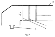
前で説明した2つの実施形態では、本発明による分離システムが、鉛直方向のガス流内に配置されている。しかし、図3および図4に示した実施形態では、ガス流が、相応して形成されたハウジング10によって水平方向に変向される。 In the two embodiments described above, the separation system according to the invention is arranged in a vertical gas flow. However, in the embodiment shown in FIGS. 3 and 4, the gas flow is diverted horizontally by a correspondingly formed housing 10.
図3に示した実施形態では、粗分離器6と精密分離器1と最終分離器5とが、1つのハウジング範囲に位置しており、このハウジング範囲には、ほぼ水平方向のガス流が形成される。前で説明した2つの実施形態の場合のように、粗分離器6は、たとえばフラット式分離器または管式分離器として形成されており、精密分離器1は、たとえば多板式分離器として設計として形成されており、最終分離器5は、たとえば管式分離器として形成されていてよい。
In the embodiment shown in FIG. 3, the
図4に示した実施形態は、本発明による分離システムのさらに別の変化形である。この分離システムでは、粗分離器6も第1の精密分離器1も、ハウジング10の、ほぼ鉛直方向のガス流が生ぜしめられる範囲に配置されている。
The embodiment shown in FIG. 4 is yet another variation of the separation system according to the present invention. In this separation system, both the
ガス流方向で見て下流側の別の精密分離器1′および最終分離器5は、ハウジング10の、水平方向のガス流が生ぜしめられる範囲に配置されている。
The
図5に示した実施形態は、鉛直方向のガス流7内の単に2段式の本発明による分離システムを示している。この分離システムは、第1の支持構造体3に支承された粗分離器8を有しており、この粗分離器8はフラット式分離器として形成されている。この粗分離器8の清浄化のためには、ガス流方向で見て前後に、つまり上流側と下流側とに洗浄装置2が配置されている。粗分離器8の上方に設けられた第2の支持構造体3′には、既に最終分離器5が配置されており、この最終分離器5は管式分離器として形成されている。図5に示した実施形態においては精密分離器が存在しないことに基づいて、この実施形態は、前で説明した分離能力よりも低い全体分離能力を有する。
The embodiment shown in FIG. 5 shows a simple two-stage separation system according to the invention in the
Claims (10)
ガス流方向(7)で前記粗分離器(6,8)と前記最終分離器(5)との間に、少なくとも1つの精密分離器(1,1′)が配置されており、当該精密分離器が、多板式分離器であり、
前記最終分離器(5)は、管式分離器として形成されており、
前記最終分離器(5)は、最後の分離段であり、
前記最終分離器(5)に対する洗浄装置が設けられていない、
ことを特徴とする、煙道ガス流から液滴を分離する分離システム。 Separation system for separating droplets from a flue gas stream for incorporation into a gas scrubber of a power plant or incinerator, comprising a coarse separator upstream of the gas stream direction (7) (6, 8) And a final separator (5) downstream in the gas flow direction (7),
At least one fine separator (1, 1 ') is arranged between the coarse separator (6, 8) and the final separator (5) in the gas flow direction (7). Is a multi-plate separator,
The final separator (5) is formed as a tubular separator;
It said final separator (5) is Ri final separation stage der,
No cleaning device is provided for the final separator (5),
A separation system for separating droplets from a flue gas stream.
Applications Claiming Priority (3)
| Application Number | Priority Date | Filing Date | Title |
|---|---|---|---|
| DE202010016752.3 | 2010-12-17 | ||
| DE202010016752U DE202010016752U1 (en) | 2010-12-17 | 2010-12-17 | Roller separator as fine rod separator to avoid chimney rain |
| PCT/EP2011/071185 WO2012079966A1 (en) | 2010-12-17 | 2011-11-28 | Tube separator as a separator of very fine particles for reducing fine dust emissions and avoiding stack rain |
Publications (2)
| Publication Number | Publication Date |
|---|---|
| JP2014503351A JP2014503351A (en) | 2014-02-13 |
| JP5988992B2 true JP5988992B2 (en) | 2016-09-07 |
Family
ID=43734955
Family Applications (1)
| Application Number | Title | Priority Date | Filing Date |
|---|---|---|---|
| JP2013543618A Active JP5988992B2 (en) | 2010-12-17 | 2011-11-28 | Tubular separator as an ultra-precision separator to reduce fine dust emissions and avoid stack rain |
Country Status (7)
| Country | Link |
|---|---|
| US (1) | US9289708B2 (en) |
| EP (1) | EP2651537B1 (en) |
| JP (1) | JP5988992B2 (en) |
| KR (1) | KR20140023268A (en) |
| DE (1) | DE202010016752U1 (en) |
| PL (1) | PL2651537T3 (en) |
| WO (1) | WO2012079966A1 (en) |
Families Citing this family (5)
| Publication number | Priority date | Publication date | Assignee | Title |
|---|---|---|---|---|
| DE202012005859U1 (en) | 2012-06-14 | 2012-09-05 | Rea Plastik Tech Gmbh | Concept for a pollution-resistant roller separator made of thermoplastic material for use in flue gas desulphurisation |
| DE202013000664U1 (en) | 2013-01-23 | 2013-03-13 | Rea Plastik Tech Gmbh | Concept for a pollution-resistant roller separator made of thermoplastic material for use in modern flue gas desulphurisation |
| CN105879550A (en) * | 2016-05-19 | 2016-08-24 | 江苏中建材环保研究院有限公司 | Desulfurization demister device |
| DE202017106122U1 (en) * | 2017-10-10 | 2019-01-14 | Detlef Weber | Separation system of a flue gas desulphurisation plant of a ship |
| CN110624348B (en) * | 2019-08-27 | 2021-05-25 | 江苏鲲鹏环保工程技术有限公司 | Environment-friendly circulating dust removal device for coal-fired power plant and dust removal process thereof |
Family Cites Families (11)
| Publication number | Priority date | Publication date | Assignee | Title |
|---|---|---|---|---|
| US4157250A (en) * | 1972-09-22 | 1979-06-05 | Ulrich Regehr | Scrubber apparatus for washing gases and having a coarse and fine droplet separator |
| DE2246474A1 (en) * | 1972-09-22 | 1974-04-04 | Regehr Ulrich | DEVICE FOR WASHING GASES |
| JPH01231923A (en) * | 1988-03-14 | 1989-09-18 | Toho Giken:Kk | Washing device for liquid to be treated |
| JP3550754B2 (en) * | 1994-10-06 | 2004-08-04 | 石川島播磨重工業株式会社 | Flue gas desulfurization equipment |
| DE19503842A1 (en) * | 1995-02-06 | 1996-08-08 | Munters Euroform Gmbh Carl | Agglomeration device |
| US6051041A (en) | 1995-02-06 | 2000-04-18 | Munters Euroform Gmbh | Separation apparatus |
| DE202005002674U1 (en) | 2005-02-19 | 2005-04-21 | Ahrens, Matthias, Dipl.-Ing. | Knock-out unit, for mounting in vertical ductwork, to remove particulate moisture from wet flue gas, has three separator elements in series |
| DE202007001942U1 (en) * | 2007-02-10 | 2007-08-16 | Munters Euroform Gmbh | Mist collector arrangement for gas scrubber, comprises downstream- and upstream mist collector layer arranged in gas flow direction, connecting rod, and device for rinsing of flow-on and flow-off sides of both mist collector layers |
| US8292992B2 (en) | 2008-01-29 | 2012-10-23 | Mitsubishi Heavy Industries, Ltd. | Flue gas desulfurization apparatus |
| DE202009004019U1 (en) * | 2009-03-20 | 2009-06-18 | Rea Plastik Tech Gmbh | Horizontally streamed drop separator with tubular baffles for flue gas streams with very high liquid loading |
| DE202010007266U1 (en) * | 2010-05-26 | 2010-10-07 | Rea Plastik Tech Gmbh | Vertically flowed droplet with tubular baffles for flue gas streams with very high liquid loading and high gas velocity |
-
2010
- 2010-12-17 DE DE202010016752U patent/DE202010016752U1/en not_active Expired - Lifetime
-
2011
- 2011-11-28 PL PL11788183T patent/PL2651537T3/en unknown
- 2011-11-28 KR KR1020137018821A patent/KR20140023268A/en not_active Application Discontinuation
- 2011-11-28 JP JP2013543618A patent/JP5988992B2/en active Active
- 2011-11-28 EP EP11788183.9A patent/EP2651537B1/en active Active
- 2011-11-28 WO PCT/EP2011/071185 patent/WO2012079966A1/en active Application Filing
- 2011-11-28 US US13/994,132 patent/US9289708B2/en not_active Expired - Fee Related
Also Published As
| Publication number | Publication date |
|---|---|
| DE202010016752U1 (en) | 2011-03-10 |
| WO2012079966A1 (en) | 2012-06-21 |
| JP2014503351A (en) | 2014-02-13 |
| PL2651537T3 (en) | 2017-09-29 |
| EP2651537B1 (en) | 2017-04-12 |
| EP2651537A1 (en) | 2013-10-23 |
| US20130263742A1 (en) | 2013-10-10 |
| US9289708B2 (en) | 2016-03-22 |
| KR20140023268A (en) | 2014-02-26 |
Similar Documents
| Publication | Publication Date | Title |
|---|---|---|
| JP5988992B2 (en) | Tubular separator as an ultra-precision separator to reduce fine dust emissions and avoid stack rain | |
| AU2009208093B2 (en) | Filtration system for gas turbines | |
| CN101660449A (en) | Filtration system for gas turbines | |
| US20040011200A1 (en) | Method of converting a downflow/upflow wet flue gas desulfurization (wfgd) system to an upflow single-loop wfgd system | |
| KR101569721B1 (en) | Fine dust reducing apparatus for stack of incinerator | |
| US8123844B2 (en) | Plugging resistant mist eliminator for horizontal gas flow built from tubular elements and vane type lamella | |
| CN102188859A (en) | Horizontal type defogger | |
| US20080257162A1 (en) | Efficient drop separator | |
| WO2023118860A1 (en) | Mist trap | |
| JPH11319480A (en) | Stack-integrated flue gas desulfurizer | |
| WO2022035385A1 (en) | Air conditioner | |
| CN105854495A (en) | Dedusting and demisting device for desulfurization technology | |
| JP6945339B2 (en) | Flue gas purification and reheating methods and equipment | |
| CN101109514A (en) | Smoke discharging system | |
| JP2000084352A (en) | Stack-integrated flue gas desulfurization unit | |
| CN102527220B (en) | Double-vortex flue gas desulfurizing, dedusting and cleaning system | |
| CN212881662U (en) | Tail gas purification device | |
| CN209978075U (en) | Smoke whitening device for boiler chimney | |
| KR200419812Y1 (en) | A wet scrubber where the 2nd scrubber is composed | |
| CN211537106U (en) | Spray condensing defroster | |
| CN211676889U (en) | Sectional type scrubbing tower | |
| CN210121394U (en) | Smoke white-eliminating and dust-removing integrated device | |
| WO2022210142A1 (en) | Gas purifying device, and liquid collecting member for gas purifying device | |
| CN106621659A (en) | Wet spraying dust collector suitable for boiler | |
| CN201171944Y (en) | Gas water separator |
Legal Events
| Date | Code | Title | Description |
|---|---|---|---|
| A621 | Written request for application examination |
Free format text: JAPANESE INTERMEDIATE CODE: A621 Effective date: 20141003 |
|
| A977 | Report on retrieval |
Free format text: JAPANESE INTERMEDIATE CODE: A971007 Effective date: 20150420 |
|
| A131 | Notification of reasons for refusal |
Free format text: JAPANESE INTERMEDIATE CODE: A131 Effective date: 20150511 |
|
| A521 | Request for written amendment filed |
Free format text: JAPANESE INTERMEDIATE CODE: A523 Effective date: 20150811 |
|
| A02 | Decision of refusal |
Free format text: JAPANESE INTERMEDIATE CODE: A02 Effective date: 20160125 |
|
| A521 | Request for written amendment filed |
Free format text: JAPANESE INTERMEDIATE CODE: A523 Effective date: 20160523 |
|
| A911 | Transfer to examiner for re-examination before appeal (zenchi) |
Free format text: JAPANESE INTERMEDIATE CODE: A911 Effective date: 20160531 |
|
| TRDD | Decision of grant or rejection written | ||
| A01 | Written decision to grant a patent or to grant a registration (utility model) |
Free format text: JAPANESE INTERMEDIATE CODE: A01 Effective date: 20160801 |
|
| A61 | First payment of annual fees (during grant procedure) |
Free format text: JAPANESE INTERMEDIATE CODE: A61 Effective date: 20160809 |
|
| R150 | Certificate of patent or registration of utility model |
Ref document number: 5988992 Country of ref document: JP Free format text: JAPANESE INTERMEDIATE CODE: R150 |
|
| R250 | Receipt of annual fees |
Free format text: JAPANESE INTERMEDIATE CODE: R250 |
|
| R250 | Receipt of annual fees |
Free format text: JAPANESE INTERMEDIATE CODE: R250 |
|
| R250 | Receipt of annual fees |
Free format text: JAPANESE INTERMEDIATE CODE: R250 |
|
| R250 | Receipt of annual fees |
Free format text: JAPANESE INTERMEDIATE CODE: R250 |
|
| R250 | Receipt of annual fees |
Free format text: JAPANESE INTERMEDIATE CODE: R250 |