JP5986122B2 - Discharge detection apparatus, discharge detection method, and printing apparatus - Google Patents
Discharge detection apparatus, discharge detection method, and printing apparatus Download PDFInfo
- Publication number
- JP5986122B2 JP5986122B2 JP2014027874A JP2014027874A JP5986122B2 JP 5986122 B2 JP5986122 B2 JP 5986122B2 JP 2014027874 A JP2014027874 A JP 2014027874A JP 2014027874 A JP2014027874 A JP 2014027874A JP 5986122 B2 JP5986122 B2 JP 5986122B2
- Authority
- JP
- Japan
- Prior art keywords
- light
- nozzle
- light emitting
- light receiving
- ejection
- Prior art date
- Legal status (The legal status is an assumption and is not a legal conclusion. Google has not performed a legal analysis and makes no representation as to the accuracy of the status listed.)
- Expired - Fee Related
Links
Images


Classifications
-
- B—PERFORMING OPERATIONS; TRANSPORTING
- B41—PRINTING; LINING MACHINES; TYPEWRITERS; STAMPS
- B41J—TYPEWRITERS; SELECTIVE PRINTING MECHANISMS, i.e. MECHANISMS PRINTING OTHERWISE THAN FROM A FORME; CORRECTION OF TYPOGRAPHICAL ERRORS
- B41J29/00—Details of, or accessories for, typewriters or selective printing mechanisms not otherwise provided for
-
- B—PERFORMING OPERATIONS; TRANSPORTING
- B41—PRINTING; LINING MACHINES; TYPEWRITERS; STAMPS
- B41J—TYPEWRITERS; SELECTIVE PRINTING MECHANISMS, i.e. MECHANISMS PRINTING OTHERWISE THAN FROM A FORME; CORRECTION OF TYPOGRAPHICAL ERRORS
- B41J2/00—Typewriters or selective printing mechanisms characterised by the printing or marking process for which they are designed
- B41J2/005—Typewriters or selective printing mechanisms characterised by the printing or marking process for which they are designed characterised by bringing liquid or particles selectively into contact with a printing material
- B41J2/01—Ink jet
- B41J2/07—Ink jet characterised by jet control
- B41J2/125—Sensors, e.g. deflection sensors
-
- B—PERFORMING OPERATIONS; TRANSPORTING
- B41—PRINTING; LINING MACHINES; TYPEWRITERS; STAMPS
- B41J—TYPEWRITERS; SELECTIVE PRINTING MECHANISMS, i.e. MECHANISMS PRINTING OTHERWISE THAN FROM A FORME; CORRECTION OF TYPOGRAPHICAL ERRORS
- B41J2/00—Typewriters or selective printing mechanisms characterised by the printing or marking process for which they are designed
- B41J2/005—Typewriters or selective printing mechanisms characterised by the printing or marking process for which they are designed characterised by bringing liquid or particles selectively into contact with a printing material
- B41J2/01—Ink jet
- B41J2/135—Nozzles
- B41J2/165—Preventing or detecting of nozzle clogging, e.g. cleaning, capping or moistening for nozzles
- B41J2/16579—Detection means therefor, e.g. for nozzle clogging
-
- B—PERFORMING OPERATIONS; TRANSPORTING
- B41—PRINTING; LINING MACHINES; TYPEWRITERS; STAMPS
- B41J—TYPEWRITERS; SELECTIVE PRINTING MECHANISMS, i.e. MECHANISMS PRINTING OTHERWISE THAN FROM A FORME; CORRECTION OF TYPOGRAPHICAL ERRORS
- B41J2/00—Typewriters or selective printing mechanisms characterised by the printing or marking process for which they are designed
- B41J2/005—Typewriters or selective printing mechanisms characterised by the printing or marking process for which they are designed characterised by bringing liquid or particles selectively into contact with a printing material
- B41J2/01—Ink jet
- B41J2/21—Ink jet for multi-colour printing
- B41J2/2132—Print quality control characterised by dot disposition, e.g. for reducing white stripes or banding
- B41J2/2142—Detection of malfunctioning nozzles
Description
本発明は、液体を吐出する複数のノズルを配列した液体吐出ヘッドにおいて不吐出などのノズルの状態を検出する吐出検出装置、吐出検出方法、及び印刷装置に関する。 The present invention relates to an ejection detection apparatus, an ejection detection method, and a printing apparatus that detect a nozzle state such as non-ejection in a liquid ejection head in which a plurality of nozzles that eject liquid are arranged.
液体吐出記録装置は、液体吐出ヘッドに設けられた複数のノズルからインク滴などの液滴を記録媒体上に吐出して画像記録を行う。このため、液体吐出ヘッドの各ノズルの吐出状態の良否が画像品質に大きく影響を及ぼす。そこで液体吐出記録装置では、記録画像の品質を維持すべく、各ノズルにおける液滴の吐出状態を検出する吐出検出装置によって定期的にあるいは任意のタイミングで液滴の吐出を検出することにより、不吐出などのノズルの状態を検出することが行われる。 A liquid discharge recording apparatus performs image recording by discharging liquid droplets such as ink droplets from a plurality of nozzles provided in a liquid discharge head onto a recording medium. For this reason, the quality of the discharge state of each nozzle of the liquid discharge head greatly affects the image quality. Therefore, in the liquid discharge recording apparatus, in order to maintain the quality of the recorded image, the discharge detection apparatus that detects the discharge state of the liquid droplets at each nozzle detects the discharge of the liquid droplets periodically or at an arbitrary timing. A state of the nozzle such as discharge is detected.
このような吐出検出装置としては、液滴の飛翔経路に交差するように検出光を出射する発光部としての発光素子(LED)と、この検出光を受光する受光部としての受光素子(フォトダイオード)とを配置したものがある。この吐出検出装置では、吐出された液滴が検出光の光路上を通過した時の受光素子の光量変化を捉えることにより不吐出ノズルの有無を検出している。すなわち、液滴を吐出したタイミングと受光素子が液滴の遮光による光量変化を検出したタイミングとに基づき、液滴の通過の有無、つまり不吐出ノズルの有無を検出することができる。 As such an ejection detection device, a light emitting element (LED) as a light emitting unit that emits detection light so as to intersect a flight path of a droplet, and a light receiving element (photodiode as a light receiving unit that receives the detection light) ). In this ejection detection device, the presence or absence of a non-ejection nozzle is detected by capturing the change in the light amount of the light receiving element when the ejected liquid droplet passes through the optical path of the detection light. That is, it is possible to detect whether or not a droplet has passed, that is, whether or not there is a non-ejection nozzle, based on the timing at which the droplet is ejected and the timing at which the light receiving element detects a change in the amount of light due to the light shielding of the droplet.
発光素子と受光素子との距離は、液体吐出ヘッドのノズル列中の全ノズルが、その間に形成される検出光の光路上に収まるようにするため、ノズル数が多くなる程長くなる。このため、発光素子と受光素子は、検出精度の向上あるいは検出機構の省スペース化を図る観点から、その間にノズル列が収まる最小限の距離となるように配置される。 The distance between the light emitting element and the light receiving element becomes longer as the number of nozzles increases in order to make all the nozzles in the nozzle row of the liquid ejection head fit on the optical path of the detection light formed therebetween. For this reason, the light emitting element and the light receiving element are arranged so as to have a minimum distance within which the nozzle row can be accommodated from the viewpoint of improving the detection accuracy or saving the space of the detection mechanism.
一方、発光素子から出射される検出光は発散光であるため、発光素子に近いノズルから吐出された液滴に遮られる光は光回折の影響を受け易い。よって、ノズルの発光素子からの距離と光回折との相関関係から、ノズル位置が発光素子に近い程、液滴によって遮光されるべき光が回析により受光素子まで到達してしまうので液滴の有無による受光量の変化が小さくなる傾向にある。また、光の放射強度は距離の2乗に反比例して弱くなることから、ノズル位置が発光素子から遠い程、光量が減少し液滴の有無に関わらず受光素子による受光量は小さくなる傾向にある。図14の従来の吐出検出装置のノズル位置と受光電流との関係を示す概略図に示すように、ノズル位置が発光素子(LED)に近づくにつれて上述したように液滴の有無による受光量の変化が小さくなるので受光量の変化に対応する検出出力値は次第に低下する。さらに吐出ノズル位置が発光素子から離れる(受光素子に近づく)につれても上述したように受光量の変化を示す検出出力値が次第に低下する。 On the other hand, since the detection light emitted from the light emitting element is diverging light, the light blocked by the liquid droplets ejected from the nozzle close to the light emitting element is easily affected by light diffraction. Therefore, from the correlation between the distance of the nozzle from the light emitting element and the light diffraction, the closer the nozzle position is to the light emitting element, the light that should be shielded by the droplet reaches the light receiving element by diffraction. The change in the amount of received light due to the presence or absence tends to be small. Also, since the light emission intensity becomes weaker in inverse proportion to the square of the distance, the farther the nozzle position is from the light emitting element, the smaller the amount of light and the smaller the amount of light received by the light receiving element regardless of the presence or absence of droplets. is there. As shown in the schematic diagram showing the relationship between the nozzle position and the light receiving current of the conventional discharge detection apparatus in FIG. 14, as described above, as the nozzle position approaches the light emitting element (LED), the change in the amount of received light due to the presence or absence of droplets. Therefore, the detection output value corresponding to the change in the amount of received light gradually decreases. Further, as described above, the detection output value indicating the change in the amount of received light gradually decreases as the discharge nozzle position moves away from the light emitting element (closer to the light receiving element).
このように、受光量の変化を検出する受光素子の検出出力レベルは、検出される液滴を吐出するノズルの位置が発光素子に近接する場合と、発光素子から離れた受光素子に近接する場合と、発光素子と受光素子との中間付近である場合とで大きく異なり、全ノズルに対して均一かつ安定した検出が行えなくなるという問題があった。 In this way, the detection output level of the light receiving element that detects the change in the amount of received light is the case where the position of the nozzle that discharges the detected liquid droplet is close to the light emitting element and when the position is close to the light receiving element that is far from the light emitting element. There is a problem that the detection is uniform and stable with respect to all the nozzles.
この問題を解決するために、特許文献1には液滴の吐出状態を光学的に検知する技術として、発光側に近いノズルの吐出滴数を多く、受光側に近いノズルの吐出滴数を少なくすることで液滴検知時の検出出力が略同一になるようにする技術が開示されている。また、特許文献2には、ノズルとセンサとの距離に応じて吐出量滴径を大きくする技術が開示されている。
In order to solve this problem,
しかし、上記特許文献1および2に係る技術では、検出専用に吐出滴数あるいは滴径を制御可能にする構成が必要となるという問題があり、さらには記録に寄与しない液体をより多く消費することになる、という問題もあった。また、検出時には実際の記録動作とは異なる吐出滴数や吐出滴径で吐出するため、吐出状態の検出時には吐出できていても実際の記録動作時には吐出滴数や吐出滴径が減少するので各ノズルの記録素子(ヒータまたはピエゾなど)に供給するエネルギーが小さくなったときには、吐出不良を起こす可能性があった。
However, the techniques according to
本発明は、ノズルの状態を適正に検出することが可能な吐出検出装置の提供を目的とする。 An object of this invention is to provide the discharge detection apparatus which can detect the state of a nozzle appropriately .
上記課題を解決するため、本発明は以下の構成を備える。
すなわち、本発明の第1の形態は、複数のノズルから吐出される液体に向けて発光部から光を発し、受光部が受光する光に基いて、前記液体を吐出したノズルの状態を検出する吐出検出装置であって、検出する前記ノズルの位置が前記発光部から遠いほど前記発光部の発光量または前記受光部の受光感度を上げるように、前記ノズルの位置に応じて前記発光量または前記受光感度を予め決定されている値に変更する制御手段を備えることを特徴とする。
In order to solve the above problems, the present invention comprises the following arrangement.
That is, in the first aspect of the present invention, light is emitted from the light emitting unit toward the liquid ejected from the plurality of nozzles, and the state of the nozzle that ejected the liquid is detected based on the light received by the light receiving unit. a discharge detection device, so that the position of the nozzle to detect the increase the light receiving sensitivity of the light-emitting amount or the light receiving portion of farther the light emitting portion from said light emitting unit, also before Symbol emission amount according to the position of the nozzle It is characterized in that it comprises a control means for changing the value that is determined in advance before Symbol receiving sensitivity.
また、本発明の第2の形態は、複数のノズルから吐出される液体に向けて発光部から光を発し、受光部が受光する光に基いて、前記液体を吐出したノズルの状態を検出する吐出検出装置であって、検出する前記ノズルの位置が前記発光部に近いほど前記発光部の発光量または前記受光部の受光感度を下げるように、前記ノズルの位置に応じて前記発光量または前記受光感度を予め決定されている値に変更する制御手段を備えることを特徴とする。
また、本発明の第3の形態は、複数のノズルから吐出される液体に向けて発光部から光を発し、受光部が受光する光に基いて、前記液体を吐出したノズルの状態を検出する吐出検出装置であって、検出する前記ノズルの位置が前記発光部に最も近接する位置にあるノズルから所定ノズルまでは前記発光部に近いほど前記発光部の発光量または前記受光部の受光感度を下げ、前記所定ノズルより前記発光部から遠い別の所定ノズルからは前記発光部に遠いほど前記発光部の発光量または前記受光部の受光感度を上げるように、前記ノズルの位置に応じて前記発光量または前記受光感度を予め決定されている値に変更する制御手段を備えることを特徴とする。
また、本発明の第4の形態は、複数のノズルから吐出される液体に向けて発光部から光を発し、受光部が受光する光に基いて、前記液体を吐出したノズルの状態を検出する検出方法であって、検出する前記ノズルの位置が前記発光部から遠いほど、前記発光部の発光量又は前記受光部の受光感度を上げるように、前記ノズルの位置に応じて前記発光量または前記受光感度を予め決定されている値に変更することを特徴とする。
In the second embodiment of the present invention, light is emitted from the light emitting unit toward the liquid ejected from the plurality of nozzles, and the state of the nozzle that ejects the liquid is detected based on the light received by the light receiving unit. a discharge detection device, so that the position of the nozzle for detecting the lower the light receiving sensitivity of the light-emitting amount or the light receiving portion of the more the light emitting portion closer to the light emitting portion, also before Symbol emission amount according to the position of the nozzle It is characterized in that it comprises a control means for changing the value that is determined in advance before Symbol receiving sensitivity.
In the third aspect of the present invention, light is emitted from the light emitting unit toward the liquid ejected from the plurality of nozzles, and the state of the nozzle that ejected the liquid is detected based on the light received by the light receiving unit. In the discharge detection device, the light emission amount of the light emitting unit or the light receiving sensitivity of the light receiving unit is increased as the position of the nozzle to be detected is closer to the light emitting unit from a nozzle closest to the light emitting unit to a predetermined nozzle. The light emission is reduced according to the position of the nozzle so as to increase the light emission amount of the light emitting unit or the light receiving sensitivity of the light receiving unit as it is farther from the light emitting unit from another predetermined nozzle farther from the light emitting unit than the predetermined nozzle. Control means for changing the quantity or the light receiving sensitivity to a predetermined value is provided.
In the fourth embodiment of the present invention, light is emitted from the light emitting unit toward the liquid ejected from the plurality of nozzles, and the state of the nozzle that ejected the liquid is detected based on the light received by the light receiving unit. In the detection method, the light emission amount or the light amount depending on the position of the nozzle so that the light emission amount of the light emission unit or the light reception sensitivity of the light reception unit increases as the position of the nozzle to be detected is farther from the light emission unit. The light receiving sensitivity is changed to a predetermined value.
また、本発明の第5の形態は、印刷ヘッドに配列された複数のノズルから液体を吐出させることによって記録媒体に画像を形成する印刷装置であって、上記吐出検出装置を備えることを特徴とする。 According to a fifth aspect of the present invention, there is provided a printing apparatus for forming an image on a recording medium by discharging liquid from a plurality of nozzles arranged in a print head, comprising the discharge detection apparatus. To do.
本発明によれば、ノズルの状態を適正に検出することができる。 According to the present invention, the state of the nozzle can be detected appropriately.
以下に、本発明の実施形態について図面を参照しつつ詳細に説明する。 Hereinafter, embodiments of the present invention will be described in detail with reference to the drawings.
(第1の実施形態)
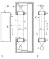
図1は本実施形態における印刷装置の外観構成を示す斜視図である。ここに示す印刷装置は、大判の記録を行うインクジェット記録方式の印刷装置を例に取り説明する。印刷装置10は、パーソナルコンピュータ(PC)1等の外部装置に通信ケーブル2等を介して接続され、外部装置からの印刷指示と共に送られてくる画像データに基づいて印刷動作を行う。またここに示す印刷装置10は、印刷媒体Pを副走査方向(Y方向)に間欠的に搬送する搬送手段と、副走査方向と交差する主走査方向(X方向)に印刷ヘッド16(以下、単にヘッドともいう)を往復移動させる主走査手段とを有する、いわゆるシリアル型の印刷装置となっている。
(First embodiment)
FIG. 1 is a perspective view showing an external configuration of a printing apparatus according to the present embodiment. The printing apparatus shown here will be described by taking an inkjet recording type printing apparatus that performs large-format recording as an example. The
印刷ヘッド16としては、吐出される液体として複数色のインクそれぞれに対応して複数個が並設されている。例えば、図2に示されるように、イエロー(Y)、マゼンタ(M)、シアン(C)、ブラック(K)などのインクそれぞれに対応して4個のヘッド100,200,300,400が並設されている。各ヘッドは複数のノズルが副走査方向(Y方向)に配列されたノズル列を有する。ここでは、図5に示すように、1番目のノズルから第1280番目のノズルが副走査方向に沿って配列されたノズル列16Aが各ヘッドに設けられている。また、本実施形態では、印刷ヘッド16が走査する走査領域端部にインク滴を適正に吐出できない不吐出ノズルを検出するための吐出検出装置30が設けられている。
A plurality of print heads 16 are juxtaposed corresponding to each of a plurality of colors of ink to be ejected. For example, as shown in FIG. 2, four
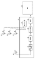
図2は、本発明の第1の実施形態における画像形成装置10の制御系の構成を示すブロック図である。ホストコンピュータ1は、インストールされた作画アプリケーションにより印刷データを作成し、通信ケーブル2は画像形成装置10にその印刷データを送信するために利用する。ホストインターフェース11は、ホストコンピュータ1からの印刷データを受信し、画像形成装置10全体の制御を行うMPU(マイクロプロセッサ)12を介してプリントバッファ24に一旦蓄える。ROM13には、起動用プログラムと圧縮された状態の制御プログラムとが格納されており、圧縮された制御プログラムは、起動時にシステムメモリ14に展開される。
FIG. 2 is a block diagram showing the configuration of the control system of the
操作パネル20は、画像形成装置10の本体操作や状態を表示するための表示装置を含む。副走査モータ18は、印刷媒体Pの搬送を行う図示しない搬送ローラを駆動する。主走査モータ19は、印刷ヘッド16が固定されている図示しないベルトを往復駆動する。印刷制御部15は、副走査モータ18及び主走査モータ19をコントロールするためのモータコントローラ17の制御及び印刷ヘッド16のインク吐出制御を行う。本実施形態における印刷ヘッド16は、ブラックヘッド100、シアンヘッド200、マゼンタヘッド300、イエローヘッド400の4色ヘッドから構成されている。但し、印刷ヘッド16は、他の色を吐出するヘッドを用いることも可能であり、さらには単一のヘッドを用いることも可能である。また、本発明においては、色材を含む液体であるインクに限らず、画像品質を向上させるための画質向上剤等の液体をノズルから吐出するヘッドを印刷ヘッド16に含めることも可能である。以下、本実施形態では、この画質向上剤等の液体も含めてインクと称すことにする。
The
次に、本実施形態において使用するノズルの状態の検出について図を用いて詳細に説明する。 Next, detection of the state of the nozzle used in the present embodiment will be described in detail with reference to the drawings.
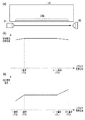
図3は、本実施形態における印刷ヘッド16と吐出検出装置30の概略構成を示す図であり、(a)は縦断側面図、(b)は概略平面図である。ヘッド16からインク滴Idを吐出させ、インク滴Idが発光素子(LED)31から受光素子であるフォトダイオード(PD)32に至る光束内を飛翔・通過することによってインク滴が遮光した時のわずかな受光量の変化を検出することが吐出検出装置の基本原理である。なお、本実施形態における単一のLED31は、本発明における発光部を構成し、フォトダイオード32は本発明における受光部を構成している。また、LED31及びPD32は、MPU12に接続された制御回路33によって制御される。
3A and 3B are diagrams showing a schematic configuration of the
吐出検出装置30は、LED31からの光をLEDスリット34を通して絞り込み、さらに外乱光の影響やミストの付着を避けるためPDスリット35を通してPD32で受光する。ヘッド16のノズル列16Aは、図3(a)に示すように、LED31からPD32までの光束LFの中にノズル配列方向(Y方向)において包含されるように配置されている。光束の中心LFcを光軸と定義すると、各ノズル列16Aと光軸LFcは互いに平行で、その間の距離間隔tは2mm〜4mmとなっている。なお、図3(b)において、LFwはノズル配列方向(Y方向)と直交する主走査方向(X方向)における光束LFの幅を示している。
The
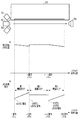
図4は、本実施形態における吐出検出装置30の制御回路33の内部構成を示すブロック図である。電流・電圧変換回路41は、フォトダイオード(PD)32に流れる電流値を電圧信号に変換して出力する。増幅回路42は、電流・電圧変換回路41から出力される電圧信号を増幅する。クランプ回路43は、インク滴の吐出に同期した制御信号により、インク滴の吐出を観測する直前に増幅回路42から出力される信号レベルを所定値に保持する。そしてインク滴の吐出が行われ、光束LF内をインク滴が飛翔して遮光し始める直前にクランプ動作を開放する。これにより、例えば低周波の外乱光が混入した場合であっても、クランプ回路43によってその影響を取り除き、固定の基準電圧に基いて検出信号を評価することができる。
FIG. 4 is a block diagram showing an internal configuration of the
比較器44は、クランプ回路43からの出力電圧を基準電圧と比較し、その比較結果を2値化してMPU12に出力している。MPU12では、ノズルから吐出されたインク滴が光束の一部を遮光したことによって生じる光量低下(光量変化)が所定量以上である期間を、2値化された比較結果に基いて求める。
The
LEDドライバ45は、LED31を駆動するためのLEDドライバである。LED31とPD32との距離間隔に対して、PD32から十分な検出出力が得られるようにLED31の駆動電流値をLEDドライバ45によって固定した場合、PD32の検出特性には、図14に示したような現象が生じる。すなわち、検出対象のノズル列16Aのうち、LED31に近いノズルからのインク滴検出では、回折現象によりインク滴によって遮光されない光の一部がPD32の受光面に到達してしまう。さらに、ヘッド16に反射した光の一部がPD32の受光面に到達してしまう。また、LED31の空間エネルギー分布特性にもよるが、一般的にはLED31から放出される光は発散光であって、その光はPD32に近づくに従いエネルギー面密度が低下するため、LED31から遠い(PD32に近い)ノズルのインク滴検出における検出光の光量が低下する。
The
そこで、本実施形態では、図5(c)に示すように、ノズルの配列位置に応じてLED駆動電流を変化させるようにLEDドライバ45から出力されるLED駆動電流を制御している。例えば、LED31に最も近い1番目ノズルからn番目ノズルにかけては、LED駆動電流を上げていくことによってLED31の発光強度を低い値から徐々に高めていく。LED31から出射される検出光は発散光であり、LED31に近いノズルから吐出されたインク滴に遮られる光は光回折の影響を受け易く、ノズル位置がLED31に近い程インク滴の有無による受光量の変化が小さくなる傾向がある。このため、本実施形態では、LED31に近いノズルほど、LED31の発光強度が小さくなるようにし、光回折の影響による受光の変化が小さくなるのを低減するようになっている。また、
ノズル列16Aの中のn番目ノズルからn+α番目ノズルにかけては、LED駆動電流を一定に保ち、n+α番目ノズルからLED31より最も遠い1280番目ノズルにかけては、発光強度を再度徐々に高くしている。このn+α番目ノズルから1280番目のノズルにかけて徐々に発光強度を高める制御は、LED31から出射された光がPDに近づくに従って減衰するのを補うために行う。
これにより、図5(b)に示すように、インクが正常に吐出されている場合に発生する受光電流の変化量をほぼ一定にすることができ、ノズル位置に応じて液体吐出滴数や液体吐出滴径を制御する必要がなく安価な回路構成で不吐出検出を行うことができる。なお、LED駆動電流を変化させる割合は、検出対象ノズルが、1番目ノズルからn番目ノズルのエリアと、n+α番目ノズルから1280番目ノズルのエリアとで異なる値となっている。これは発光するLED31の光の特性、光を反射するヘッド回りの部材の反射率あるいは受光するPD32の感度特性などにより検出するノズル位置に応じて発光強度を変化させる割合を異ならせているからである。なお、上記のようなLED31の発光強度の制御は、MPU12が制御回路33に設けられたLEDドライバ45を制御することにより行う。
Therefore, in the present embodiment, as shown in FIG. 5C, the LED drive current output from the
The LED drive current is kept constant from the nth nozzle to the n + αth nozzle in the
As a result, as shown in FIG. 5B, the amount of change in the received light current that occurs when the ink is ejected normally can be made substantially constant. It is not necessary to control the ejection droplet diameter, and non-ejection detection can be performed with an inexpensive circuit configuration. Note that the ratio of changing the LED drive current is different for the detection target nozzle area from the first nozzle area to the nth nozzle area and from the n + αth nozzle area to the 1280th nozzle area. This is because the ratio of changing the light emission intensity is varied according to the detected nozzle position based on the light characteristics of the
次に、MPU12によって実行される本実施形態の一連の不吐出検出動作を図6に示すフローチャートに沿って説明する。
Next, a series of non-ejection detection operations of this embodiment executed by the
まず、S101においてMPU12がLEDドライバ45を駆動し、不吐出検出ユニット30のLED31を点灯させる。S102では、LED31とPD32との光軸と、ヘッド16のノズル列16Aとの位置合わせを行う。なお、この動作の詳細は、後に図7に沿って説明する。S103では、しばらくインク吐出を行わなかったノズルは、増粘インクなどによる目詰まりを起こしていることがあるので、不吐出検出を行う前にノズルの目詰まりを解消するための予備吐出を行う。これは、MPU12が印刷制御部15を介して印刷ヘッド16を駆動することより行なう。
First, in S101, the
S104では、MPU12がLEDドライバ45を制御し、不吐出検出の対象となるノズル(検出対象ノズル)に応じたLED駆動電流を印加し、1つの検出対象ノズルからインクを吐出させるS105。この後、S106では前述の吐出検出装置30におけるPD32の検出電圧の変化量が所定の閾値より高いか否かに基いて、インク滴が吐出されたか否かを判断する。この判断は、吐出検出装置30に設けられた比較器44から出力された信号に基いてMPU12が行う。ここでインク滴が検出されたと判断した場合にはS107に進み、検出されなかったと判断された場合にはS108に進む。
In S104, the
前述のS106において所定の閾値より検出電圧の変化量が高く、正常にインク滴が吐出されたと判断されると、S107では、少なくとも全ノズル数分の容量を持つメモリにおいて、MPU12はノズル番号に対応したアドレスにその検出対象ノズルが正常であることを表すデータを書き込む。これに対し、S106において検出電圧が所定の閾値以下であり、正常にインク滴が吐出されていないと判断された場合には、S108においてMPU12は前記メモリのノズル番号に対応したアドレスに、その検出対象ノズルが不吐出ノズルであることを表すデータを書き込む。
If it is determined in S106 that the change amount of the detection voltage is higher than the predetermined threshold value and the ink droplets are ejected normally, in S107, the
S109では、S105で吐出したノズルの次に吐出を行うノズルの位置に合わせて、MPU12が制御回路33を介してLED駆動電流を設定する。この後、S110では、全ノズル数分の不吐出検出が終了したかどうかを判断する。全ノズルに対する不吐出検出が終了した場合にはS111に進み、吐出検出装置30のLED31を消灯する。また、全ノズルの不吐出検出がまだ終了していない場合には、S112で検出すべき対象ノズルを変更した後にS104に戻り、S106〜S110の処理を繰り返す。
In S109, the
以上のように図6のフローチャートに示す処理を実行することによって、不吐出ノズルの位置と、正常なインク吐出を可能とする正常ノズルの位置とがメモリに書き込まれる。従って、このメモリを参照することによって、ノズル列16Aの中の不吐出ノズル、正常ノズルを特定することが可能になる。
By executing the processing shown in the flowchart of FIG. 6 as described above, the position of the non-ejection nozzle and the position of the normal nozzle that enables normal ink ejection are written in the memory. Therefore, by referring to this memory, it becomes possible to specify the non-ejection nozzles and the normal nozzles in the
次に、図6のS102に示した光軸合わせにおいて実行される一連の動作を図7のフローチャートに沿って詳細に説明する。 Next, a series of operations executed in the optical axis alignment shown in S102 of FIG. 6 will be described in detail with reference to the flowchart of FIG.
S201では、特定の1ノズルについて所定のサイクルでインク吐出を繰り返し行う。次に、S202では、吐出検出装置30が固定された状態で、吐出検出装置30の光軸LFcに対して、ヘッド16を所定のホームポジション位置から主走査方向(X方向)に移動していく。なお、主走査方向(X方向)は、吐出検出装置30の光軸LFcに対して直交する方向であって、図3(a)では紙面に直交する方向を指す。この後、S203では、ヘッド16を移動させながらインク滴が検出されたかどうかを判断する。この検出は、前述のように吐出検出装置30におけるPD32の検出電圧の変化量が所定の閾値より高いか否かに基いて、インク滴が検出されたか否かを判断する。インク滴が検出された場合には、S204に進み、検出されなかった場合には、S202に戻りヘッド16を主走査方向に更に移動する。
In S201, ink discharge is repeatedly performed in a predetermined cycle for a specific nozzle. Next, in S202, the
S204では、S203によりインク滴が検出されたと判断されると、その時のヘッド16の位置を、図3(b)に示すエッジ1としてヘッド位置を記憶するためのメモリに書き込む。その後S205では、ヘッド16を主走査方向に更に移動させる。S206では、ヘッド16を移動させながらインク滴が検出されたかどうかを判断する。ここでインク滴が検出されなくなった場合には、S207に進み、インク適が検出されなくなった時のヘッド16の位置を、図3(b)に示すエッジ2として前述のヘッド位置を記憶するためのメモリに書き込む。また、S206においてインク滴が検出され続けている場合には、S205に戻りヘッド16を更に主走査方向に移動する。S204とS207とで検出したエッジ1とエッジ2の中間位置は光束LFの中心位置である光軸LFcに相当する。このため、MPU12は、S208においてエッジ1とエッジ2の中間位置を求め、その中間位置にヘッド16を移動させる。これにより、吐出検出装置30における光軸とヘッド16のノズル列との位置合わせ(光軸合わせ)が完了する。
In S204, if it is determined that an ink droplet has been detected in S203, the position of the
以上、本実施形態では、1つのヘッド16に対して不吐出検出を行なう場合を説明したが、液体吐出装置に搭載された複数のヘッドの不吐出検出も同様にして行うことが可能であることは明らかである。すなわち、各記録ヘッドのノズル列に対し、図6に示す動作を順次実行することで、全てのノズル列における不吐出検出を行うことができる。
As described above, in this embodiment, the case where non-ejection detection is performed on one
また、ノズル列の不吐出検出は、ノズル列の中の1番目のノズル(LED31に最も近いノズル)から行う必要はなく、LED31の駆動電流値とインク吐出位置との関係が合っていれば任意のノズルから不吐出検出を開始することも可能である。
Further, the non-ejection detection of the nozzle row does not need to be performed from the first nozzle (the nozzle closest to the LED 31) in the nozzle row, and is arbitrary as long as the relationship between the drive current value of the
以上のように、この第1の実施形態によれば、ヘッド16の各ノズルにおけるノズル位置に応じて液体吐出滴数や液体吐出滴径を変化させるという複雑かつ困難な制御を必要とせず、発光部であるLED31の光量調整を行うという安価な構成によって高精度に不吐出などのノズル状態の検出を行うことが可能になる。
As described above, according to the first embodiment, the complicated and difficult control of changing the number of liquid ejection droplets and the liquid ejection droplet diameter according to the nozzle position of each nozzle of the
(第2の実施形態)
次に、本発明の第2の実施形態を説明する。
上記第1の実施形態では、1個のLEDで光量調整を行う場合を示したが、第2の実施形態では、発光量の低い安価なLEDを複数個使用して光量調整を行うものとなっている。図8は第2の実施形態におけるヘッド16と吐出検出装置50の概略図を示す。第2実施形態においてもヘッド16から吐出させたインク滴Idが、発光素子(LED51〜53)から受光素子(PD56)に至る光束を通過して遮光した時の僅かな受光量の変化を検出することが不吐出検出の基本原理であることは第1の実施形態と同様である。
(Second Embodiment)
Next, a second embodiment of the present invention will be described.
In the first embodiment, the case where the amount of light is adjusted by one LED is shown. However, in the second embodiment, the amount of light is adjusted by using a plurality of inexpensive LEDs having low light emission amounts. ing. FIG. 8 is a schematic view of the
吐出検出装置50は、凸レンズ(光学系)54の焦点f1を通った光が、光軸LFcに対して平行な光線となる特性を利用し、3個のLED51〜LED53の光をそれぞれ平行な状態でPD側の凸レンズ55に入射させる。PD側の凸レンズ55を通った光は、焦点位置f2にあるPD56で受光される。ヘッド16のノズル列はLED側の凸レンズ54で集光されてPD側の凸レンズ56に至る光束の中に、ノズル配列方向(Y方向)において包含されるように配置されている。
The
図9は、本発明における制御回路57の内部構成を示すブロック図である。図9に示す制御回路57は、電流・電圧変換回路61、増幅回路62、クランプ回路63、比較器64およびLEDドライバ65を備える。このうち、制御回路57は、MPU112の制御によって、電流・電圧変換回路61、増幅回路62、クランプ回路63、比較器64は、第1の実施形態において示したフォトダイオードPD32、電流・電圧変換回路41、増幅回路42、クランプ回路43と同様である。従って、これらについて説明は省略する。第2の実施形態における制御回路57は、MPU112の制御によって、3個のLED51〜53を同時に駆動することが可能なLEDドライバ65を備えるものとなっており、この点が上記第1の実施形態と異なる。
FIG. 9 is a block diagram showing the internal configuration of the
次にLED51〜53の駆動方法について、図10を用いて説明する。第2の実施形態においては、1番目ノズルからn番目ノズルに至る第1駆動エリアでは、LED51のみを使用してLED駆動電流を上げていき、発光強度を低い値から徐々に高くしている。また、n番目ノズルからn+α番目ノズルに至る第2駆動エリアでは、LED51とLED52を共に駆動し、各々のLED駆動電流を一定に保ち、発光強度を一定にしている。さらに、n+α番目ノズルから1280番目ノズルに至る第3駆動エリアでは、3つのLED51、52、53を全て駆動し、ノズルの配列位置に応じて各々のLED駆動電流を上げていき発光強度を徐々に高くしていく。これにより、受光電流をほぼ一定にすることができ、検出範囲を広くとることなく、安価な構成で適正な不吐出検出を安定して行うことが可能になる。
Next, a method for driving the
次に、MPU112によって実行される本実施形態の一連の不吐出検出動作を図11に示すフローチャートに沿って説明する。
Next, a series of ejection failure detection operations of the present embodiment executed by the
まず、S301においてMPU112がLEDドライバ65を駆動し、不吐出検出ユニット50のLED51を点灯させる。S302では、LED51とPD56の光軸合わせを行う。この光軸合わせの処理は、第1の実施形態で説明した図7に示す動作と同様なので、重複説明は省略する。S303では、不吐出検出を行う前にノズルの目詰まりを解消するための予備吐出を行う。
First, in S301, the
S304では不吐出検出の対象となる図10で示した第1駆動エリアに属するノズル(検出対象ノズル)に応じたLED駆動電流を印加し(S304)、1つの検出対象ノズルからインクを吐出させる(S305)。次に、S306では、吐出検出装置50におけるPD56の検出電圧が所定の閾値より高いか否かに基いて、インク滴が検出されたか否かを判断する。ここで、インク滴が検出されたと判断した場合にはS307に進み、検出されなかったと判断された場合にはS307に進む。
In S304, an LED drive current corresponding to the nozzles (detection target nozzles) belonging to the first drive area shown in FIG. 10 to be subjected to non-ejection detection is applied (S304), and ink is ejected from one detection target nozzle ( S305). Next, in S306, it is determined whether an ink droplet has been detected based on whether the detection voltage of the
S308では、インク滴が正常に吐出されたと判断されると、全ノズル数分の容量を持つメモリにおいて、MPU112がノズル番号に対応したアドレスに、その検出対象ノズルが正常であることを表すデータを書き込む。また、S308では、インク滴が吐出されていないと判断されると、全ノズル数分の容量を持つメモリにおいて、MPU112がノズル番号に対応したアドレスにその検出対象ノズルが不吐出ノズルであることを表すデータを書き込む。
In S308, when it is determined that the ink droplets are ejected normally, data indicating that the detection target nozzle is normal is stored in an address corresponding to the nozzle number in the memory having a capacity corresponding to the number of all nozzles. Write. In S308, if it is determined that no ink droplets are ejected, the
S309では、MPU112がS304で吐出したノズルの次に吐出を行うノズル位置が図10で示した第2駆動エリアに属するか否かの判断を行い、第2駆動エリアに属すると判断された場合にはS310に進み、第2駆動エリアに属さないと判断された場合にはS312に進む。S309では、MPU112が吐出検出装置50のLED51を点灯させた状態のまま、LED52をさらに点灯する。このLED51,52の駆動において、S311では、LED51及びLED52に対して、S305で吐出したノズルの次に吐出を行うノズルの位置に合わせて、LED駆動電流を設定する。この後、S312では、MPU112がS305で吐出したノズルの次に吐出を行うノズル位置が図10で示した第3駆動エリアに属するか否かの判断を行い、第3駆動エリアに属する場合には、S313に進み、第3駆動エリアでない場合にはS317に進む。
In S309, it is determined whether or not the nozzle position at which the
S313では、MPU112が吐出検出装置50のLED51を点灯させた状態のまま、さらにLED52及びLED53を点灯する。このとき、S314では、LED51、LED52、LED53のそれぞれに対して、S305で吐出したノズルの次に吐出を行うノズルの位置に合わせてLED駆動電流を設定する。この後、S315では、全ノズル数分の不吐出検出が終了したか否かを判断する。そして、全ノズルの不吐出検出が終了した場合には、S316に進み、吐出検出装置50のLED51、LED52、LED53を消灯する。また、全ノズルの不吐出検出がまだ終了していない場合にはS318で検出すべき対象ノズルを変更した後にS304に戻り、前述のS304以降の処理を行う。また、S312において、次のノズル位置が第3駆動エリアに属さないと判断された場合にはS317に進み、吐出検出装置50のLED52、LED53を消灯する。
In S313, the
以上のように図11のフローチャートに示す処理を実行することによって、MPU112が不吐出ノズルの位置と、正常なインク吐出を可能とする正常ノズルの位置とをメモリに書き込む。従って、このメモリを参照することによって、ノズル列16Aの中の不吐出ノズル、正常ノズルを特定することが可能になる。しかも、この第2の実施形態においては、発光量の低い安価な3個のLED51,52,53を使用して光量調整を行うものとなっており、LED51,52,53を駆動するLEDドライバも1個のLEDを駆動する場合と略同様の構成であるため、駆動回路のコストが増大することもない。
By executing the processing shown in the flowchart of FIG. 11 as described above, the
さらに、ノズル列の不吐出検出は、ノズル列の中の1番目のノズル(LED51〜53に最も近いノズル)から行う必要はなく、LED51〜53の駆動電流値とインク吐出位置との関係が合っていれば任意のノズルから不吐出検出を開始することも可能である。
Further, the non-ejection detection of the nozzle row does not need to be performed from the first nozzle (the nozzle closest to the
なお、上記各実施形態においては、シリアル型の印刷装置を例に採り説明したが、本発明は、記録媒体を連続的に搬送しつつ定位置に固定された印刷ヘッドを用いて印刷を行う、いわゆるフルライン型の印刷装置にも本発明は適用可能である。フルライン型の印刷装置における印刷ヘッドは、使用する印刷媒体の幅以上の幅に亘ってノズルを配列した長尺ヘッドを用いるのが通例である。従って、この場合には、上記第2の実施形態におけるように、複数の発光素子を用いて受光素子との間に光束を形成するようにすれば、長尺ヘッドへの対応も容易であり、良好な不吐出検出を実現することができる。 In each of the above embodiments, a serial type printing apparatus has been described as an example, but the present invention performs printing using a print head that is fixed in place while continuously conveying a recording medium. The present invention can also be applied to a so-called full line type printing apparatus. As a print head in a full-line type printing apparatus, it is usual to use a long head in which nozzles are arranged over the width of the print medium to be used. Therefore, in this case, as in the second embodiment, if a light beam is formed between the light receiving elements using a plurality of light emitting elements, it is easy to handle a long head. Good non-discharge detection can be realized.
上記第1および第2の実施形態では、ノズル列16Aの中のエリアのうち中間位置に存在するエリア内のノズル、すなわちn番目ノズルからn+α番目ノズルのエリアにおいては、LED駆動電流を一定に保つようにした。しかし、本発明はこれに限定されるものではなく、図12に示すように、n番目ノズルからn+α番目ノズルのエリアにおいても、発光強度を徐々に高くするようにしても良い。
In the first and second embodiments described above, the LED drive current is kept constant in the nozzles in the middle position among the areas in the
(第3の実施形態)
次に本発明の第3の実施形態を説明する。
上記第1及び第2の実施形態では液体の吐出状態を検出すべきノズルの位置に応じて発光部の発光強度を変化させたが、この第3の実施形態では発光部の発光強度を変化させずに図13に示す検出装置70により、検出すべきノズルの位置に応じて受光部の受光感度を変化させるものとなっている。
(Third embodiment)
Next, a third embodiment of the present invention will be described.
In the first and second embodiments, the light emission intensity of the light emitting unit is changed according to the position of the nozzle to detect the liquid discharge state. In the third embodiment, the light emission intensity of the light emitting unit is changed. Instead, the
第3の実施形態では、第1及び第2の実施形態の制御回路33を図13に示すような制御回路77を有する吐出検出装置に置き換えたものであり、その他の構成は上記第1の実施形態と同様である。なお、図13中、上記各実施形態に示したものと同一部分には同一符号を付し、その説明の詳細は省く。
図13に示す吐出検出装置は、発光部としてのLED31から発せられた光を受光する受光部としてのフォトダイオード(PD)72の受光感度を、検出するノズルの位置に応じてデジタル・ポテンショメータ71の負荷抵抗をMPU212からのコントロール信号により調節する機能を備える。この点が第3の実施形態と第1及び第2の実施形態とで異なる。
In the third embodiment, the
The discharge detection device shown in FIG. 13 is configured to detect the light receiving sensitivity of a photodiode (PD) 72 serving as a light receiving unit that receives light emitted from an
なお、第3の実施形態において、発光部の発光強度を変化させることと受光部の受光感度を変化させることを合わせて実施することもできる。フォトダイオード72の感度の調整は、LED31から発せられた発光強度の変化に伴って調整するようにすることも可能である。また、検出するノズルの位置に応じて受光感度を変化させる割合を異ならせるようにしても良い。
Note that in the third embodiment, changing the light emission intensity of the light emitting unit and changing the light receiving sensitivity of the light receiving unit can be performed together. The sensitivity of the
12,112,212 MPU
16 印刷ヘッド
16A ノズル列
30,50,70 吐出検出装置
31 LED(発光部)
32,51,52,53,72 フォトダイオード(受光部)
33,57,77吐出検出装置の制御回路
71 デジタル・ポテンショメータ
72 フォトダイオード(受光部)
Id インク滴
12, 112, 212 MPU
16
32, 51, 52, 53, 72 Photodiode (light receiving part)
33, 57, 77 Discharge detection
Id ink drop
Claims (7)
検出する前記ノズルの位置が前記発光部から遠いほど前記発光部の発光量または前記受光部の受光感度を上げるように、前記ノズルの位置に応じて前記発光量または前記受光感度を予め決定されている値に変更する制御手段を備えることを特徴とする吐出検出装置。 A discharge detection device that emits light from a light emitting unit toward a liquid discharged from a plurality of nozzles and detects a state of the nozzle that discharges the liquid based on light received by a light receiving unit,
So that the position of the nozzle to detect the increase the light receiving sensitivity of the light-emitting amount or the light receiving portion of farther the light emitting portion from said light emitting portion, is previously determined the amount of light emission or the light receiving sensitivity according to the position of the nozzle ejection exit detector you comprising a control means for changing the am values.
検出する前記ノズルの位置が前記発光部に近いほど前記発光部の発光量または前記受光部の受光感度を下げるように、前記ノズルの位置に応じて前記発光量または前記受光感度を予め決定されている値に変更する制御手段を備えることを特徴とする吐出検出装置。 A discharge detection device that emits light from a light emitting unit toward a liquid discharged from a plurality of nozzles and detects a state of the nozzle that discharges the liquid based on light received by a light receiving unit,
So that the position of the nozzle for detecting the lower the light receiving sensitivity of the light-emitting amount or the light receiving portion of the light emitting portion closer to the front Symbol emitting portion is predetermined the amount of light emission or the light receiving sensitivity according to the position of the nozzle further comprising a control means for changing the in which the value ejection exit detector you said.
検出する前記ノズルの位置が前記発光部に最も近接する位置にあるノズルから所定ノズルまでは前記発光部に近いほど前記発光部の発光量または前記受光部の受光感度を下げ、前記所定ノズルより前記発光部から遠い別の所定ノズルからは前記発光部に遠いほど前記発光部の発光量または前記受光部の受光感度を上げるように、前記ノズルの位置に応じて前記発光量または前記受光感度を予め決定されている値に変更する制御手段を備えることを特徴とする吐出検出装置。 A discharge detection device that emits light from a light emitting unit toward a liquid discharged from a plurality of nozzles and detects a state of the nozzle that discharges the liquid based on light received by a light receiving unit,
From the nozzle in the position location of the nozzle to be detected closest to the light emitting portion to a predetermined nozzle to lower the receiving sensitivity of the light-emitting amount or the light receiving portion of the light emitting portion closer to the light emitting portion, the more the predetermined nozzle The light emission amount or the light reception sensitivity is previously set according to the position of the nozzle so that the light emission amount of the light emission unit or the light reception sensitivity of the light reception unit increases as the distance from another predetermined nozzle far from the light emission unit increases. ejection exit detector you comprising a control means for changing the determined by that value.
前記制御手段は、前記複数の発光素子のうち発光させる発光素子の数を変化させることで前記発光量を変化させることを特徴とする請求項1乃至4のいずれか1項に記載の吐出検出装置。 The light emitting unit includes a plurality of light emitting elements,
Wherein the control means, the discharge detection device according to any one of claims 1 to 4, characterized in that changing the light emission amount by changing the number of light emitting elements to emit light among the plurality of light emitting elements .
検出する前記ノズルの位置が前記発光部から遠いほど、前記発光部の発光量又は前記受光部の受光感度を上げるように、前記ノズルの位置に応じて前記発光量または前記受光感度を予め決定されている値に変更することを特徴とする吐出検出方法。 A method of detecting light emitted from a light emitting unit toward a liquid ejected from a plurality of nozzles and detecting a state of the nozzle ejecting the liquid based on light received by a light receiving unit,
The light emission amount or the light receiving sensitivity is determined in advance according to the position of the nozzle so as to increase the light emission amount of the light emitting unit or the light receiving sensitivity of the light receiving unit as the position of the nozzle to be detected is farther from the light emitting unit. The discharge detection method is characterized in that the value is changed to a predetermined value .
請求項1乃至5のいずれか1項に記載の吐出検出装置を備えることを特徴とする印刷装置。 A printing apparatus that forms an image on a recording medium by discharging liquid from a plurality of nozzles arranged in a print head,
Printing apparatus, characterized in that it comprises the ejection device according to any one of claims 1 to 5.
Priority Applications (2)
| Application Number | Priority Date | Filing Date | Title |
|---|---|---|---|
| JP2014027874A JP5986122B2 (en) | 2013-02-28 | 2014-02-17 | Discharge detection apparatus, discharge detection method, and printing apparatus |
| US14/193,511 US9033452B2 (en) | 2013-02-28 | 2014-02-28 | Ejection detection device, ejection detection method, and printing apparatus |
Applications Claiming Priority (3)
| Application Number | Priority Date | Filing Date | Title |
|---|---|---|---|
| JP2013039471 | 2013-02-28 | ||
| JP2013039471 | 2013-02-28 | ||
| JP2014027874A JP5986122B2 (en) | 2013-02-28 | 2014-02-17 | Discharge detection apparatus, discharge detection method, and printing apparatus |
Publications (3)
| Publication Number | Publication Date |
|---|---|
| JP2014193602A JP2014193602A (en) | 2014-10-09 |
| JP2014193602A5 JP2014193602A5 (en) | 2015-04-23 |
| JP5986122B2 true JP5986122B2 (en) | 2016-09-06 |
Family
ID=51387702
Family Applications (1)
| Application Number | Title | Priority Date | Filing Date |
|---|---|---|---|
| JP2014027874A Expired - Fee Related JP5986122B2 (en) | 2013-02-28 | 2014-02-17 | Discharge detection apparatus, discharge detection method, and printing apparatus |
Country Status (2)
| Country | Link |
|---|---|
| US (1) | US9033452B2 (en) |
| JP (1) | JP5986122B2 (en) |
Families Citing this family (4)
| Publication number | Priority date | Publication date | Assignee | Title |
|---|---|---|---|---|
| US10545844B2 (en) | 2017-09-29 | 2020-01-28 | Ricoh Company, Ltd. | Print verification system that reports defective printheads |
| CN110202934B (en) * | 2018-02-28 | 2020-11-24 | 森大(深圳)技术有限公司 | Method, device and equipment for detecting whether nozzle of spray head is abnormal or not and storage medium |
| CN110202935B (en) * | 2018-02-28 | 2020-11-10 | 森大(深圳)技术有限公司 | Nozzle detection method, device, equipment and storage medium |
| CN110370802A (en) * | 2019-07-29 | 2019-10-25 | 深圳市华星光电半导体显示技术有限公司 | Ink jet printing device and its adjusting method |
Family Cites Families (10)
| Publication number | Priority date | Publication date | Assignee | Title |
|---|---|---|---|---|
| JP3840958B2 (en) * | 2001-11-16 | 2006-11-01 | セイコーエプソン株式会社 | Ink discharge determination device, ink jet printer, and ink discharge determination method |
| JP4227395B2 (en) * | 2002-11-14 | 2009-02-18 | キヤノン株式会社 | Droplet discharge state determination method and apparatus, inkjet printer, program thereof, and storage medium |
| JP2006007447A (en) | 2004-06-22 | 2006-01-12 | Konica Minolta Holdings Inc | Inkjet recorder and detection method of discharge defective nozzle |
| JP4967234B2 (en) * | 2004-12-21 | 2012-07-04 | コニカミノルタホールディングス株式会社 | Microdroplet detection apparatus, microdroplet detection method, and inkjet recording apparatus |
| JP4652897B2 (en) * | 2005-06-14 | 2011-03-16 | キヤノン株式会社 | Droplet discharge state detection device, droplet discharge device, and ink jet recording apparatus |
| JP5339862B2 (en) * | 2008-11-19 | 2013-11-13 | キヤノン株式会社 | Discharge state detection method |
| JP5521383B2 (en) | 2009-04-23 | 2014-06-11 | 株式会社リコー | Liquid discharge failure detection device and ink jet recording device |
| JP5652263B2 (en) * | 2011-03-03 | 2015-01-14 | 株式会社リコー | Image forming apparatus and droplet discharge detection method in the image forming apparatus |
| JP2013014029A (en) * | 2011-06-30 | 2013-01-24 | Ricoh Elemex Corp | Device for detecting discharge failure, and image forming apparatus |
| JP5938889B2 (en) * | 2011-12-16 | 2016-06-22 | 株式会社リコー | Recording apparatus and control method |
-
2014
- 2014-02-17 JP JP2014027874A patent/JP5986122B2/en not_active Expired - Fee Related
- 2014-02-28 US US14/193,511 patent/US9033452B2/en not_active Expired - Fee Related
Also Published As
| Publication number | Publication date |
|---|---|
| US20140240390A1 (en) | 2014-08-28 |
| JP2014193602A (en) | 2014-10-09 |
| US9033452B2 (en) | 2015-05-19 |
Similar Documents
| Publication | Publication Date | Title |
|---|---|---|
| US8449068B2 (en) | Light-scattering drop detector | |
| JP4074920B2 (en) | Droplet detection device and droplet detection method for droplet discharge device | |
| US20050253890A1 (en) | Droplet determination device and droplet determination method for droplet discharge apparatus | |
| US6513900B2 (en) | Detection of non-operating nozzle by light beam passing through aperture | |
| JP5986122B2 (en) | Discharge detection apparatus, discharge detection method, and printing apparatus | |
| JP5652264B2 (en) | Image forming apparatus and droplet discharge detection method in the image forming apparatus | |
| JP2009502572A (en) | Droplet detection | |
| JPH11188853A (en) | Recording device and detecting method of ink spouting state | |
| JP4645812B2 (en) | Liquid ejection apparatus, image forming apparatus, and ejection detection method | |
| JP5652263B2 (en) | Image forming apparatus and droplet discharge detection method in the image forming apparatus | |
| US7413278B2 (en) | Image forming apparatus and ejection determining method | |
| US6641246B2 (en) | Detection of non-operating nozzle by light beam passing through aperture | |
| JP4645811B2 (en) | Liquid ejection apparatus, image forming apparatus, and ejection detection method | |
| JP2001310478A (en) | Ink droplet ejection test with nozzle selected | |
| JP2020090095A (en) | Recording device and determining method | |
| JP2010162909A (en) | Optical sensor for determining print operation state, printer, and method for determining print operation state | |
| JP2006007447A (en) | Inkjet recorder and detection method of discharge defective nozzle | |
| JP2007144900A (en) | Liquid droplet jet head, liquid droplet jet system, method for detecting ejection of liquid droplet, and program for detecting ejection of liquid droplet | |
| JP2005059552A (en) | Photosensor for judging print operation state, printer, and method for judging print operation state | |
| JP3162972B2 (en) | Printing apparatus and facsimile apparatus using the printing apparatus | |
| JP2008194825A (en) | Apparatus for detecting liquid poor discharge, and inkjet recorder | |
| JP2013132801A (en) | Droplet discharge detection device and image forming apparatus | |
| JP2006007446A (en) | Inkjet recorder and detection method of discharge defective nozzle | |
| JP4967234B2 (en) | Microdroplet detection apparatus, microdroplet detection method, and inkjet recording apparatus | |
| JP2014217967A (en) | Ink droplet flight state evaluation device |
Legal Events
| Date | Code | Title | Description |
|---|---|---|---|
| A521 | Request for written amendment filed |
Free format text: JAPANESE INTERMEDIATE CODE: A523 Effective date: 20150304 |
|
| A621 | Written request for application examination |
Free format text: JAPANESE INTERMEDIATE CODE: A621 Effective date: 20150304 |
|
| A131 | Notification of reasons for refusal |
Free format text: JAPANESE INTERMEDIATE CODE: A131 Effective date: 20151215 |
|
| A977 | Report on retrieval |
Free format text: JAPANESE INTERMEDIATE CODE: A971007 Effective date: 20151216 |
|
| A521 | Request for written amendment filed |
Free format text: JAPANESE INTERMEDIATE CODE: A523 Effective date: 20160215 |
|
| TRDD | Decision of grant or rejection written | ||
| A01 | Written decision to grant a patent or to grant a registration (utility model) |
Free format text: JAPANESE INTERMEDIATE CODE: A01 Effective date: 20160712 |
|
| A61 | First payment of annual fees (during grant procedure) |
Free format text: JAPANESE INTERMEDIATE CODE: A61 Effective date: 20160804 |
|
| R150 | Certificate of patent or registration of utility model |
Ref document number: 5986122 Country of ref document: JP Free format text: JAPANESE INTERMEDIATE CODE: R150 |
|
| S533 | Written request for registration of change of name |
Free format text: JAPANESE INTERMEDIATE CODE: R313533 |
|
| R350 | Written notification of registration of transfer |
Free format text: JAPANESE INTERMEDIATE CODE: R350 |
|
| LAPS | Cancellation because of no payment of annual fees |