JP5979111B2 - Crew protection device - Google Patents
Crew protection device Download PDFInfo
- Publication number
- JP5979111B2 JP5979111B2 JP2013204270A JP2013204270A JP5979111B2 JP 5979111 B2 JP5979111 B2 JP 5979111B2 JP 2013204270 A JP2013204270 A JP 2013204270A JP 2013204270 A JP2013204270 A JP 2013204270A JP 5979111 B2 JP5979111 B2 JP 5979111B2
- Authority
- JP
- Japan
- Prior art keywords
- occupant
- airbag
- vicinity
- seat
- disposed
- Prior art date
- Legal status (The legal status is an assumption and is not a legal conclusion. Google has not performed a legal analysis and makes no representation as to the accuracy of the status listed.)
- Active
Links
Images


Classifications
-
- B—PERFORMING OPERATIONS; TRANSPORTING
- B60—VEHICLES IN GENERAL
- B60R—VEHICLES, VEHICLE FITTINGS, OR VEHICLE PARTS, NOT OTHERWISE PROVIDED FOR
- B60R21/00—Arrangements or fittings on vehicles for protecting or preventing injuries to occupants or pedestrians in case of accidents or other traffic risks
- B60R21/02—Occupant safety arrangements or fittings, e.g. crash pads
- B60R21/16—Inflatable occupant restraints or confinements designed to inflate upon impact or impending impact, e.g. air bags
- B60R21/18—Inflatable occupant restraints or confinements designed to inflate upon impact or impending impact, e.g. air bags the inflatable member formed as a belt or harness or combined with a belt or harness arrangement
-
- B—PERFORMING OPERATIONS; TRANSPORTING
- B60—VEHICLES IN GENERAL
- B60R—VEHICLES, VEHICLE FITTINGS, OR VEHICLE PARTS, NOT OTHERWISE PROVIDED FOR
- B60R21/00—Arrangements or fittings on vehicles for protecting or preventing injuries to occupants or pedestrians in case of accidents or other traffic risks
- B60R21/02—Occupant safety arrangements or fittings, e.g. crash pads
- B60R21/16—Inflatable occupant restraints or confinements designed to inflate upon impact or impending impact, e.g. air bags
- B60R21/20—Arrangements for storing inflatable members in their non-use or deflated condition; Arrangement or mounting of air bag modules or components
- B60R21/207—Arrangements for storing inflatable members in their non-use or deflated condition; Arrangement or mounting of air bag modules or components in vehicle seats
-
- B—PERFORMING OPERATIONS; TRANSPORTING
- B60—VEHICLES IN GENERAL
- B60R—VEHICLES, VEHICLE FITTINGS, OR VEHICLE PARTS, NOT OTHERWISE PROVIDED FOR
- B60R21/00—Arrangements or fittings on vehicles for protecting or preventing injuries to occupants or pedestrians in case of accidents or other traffic risks
- B60R21/02—Occupant safety arrangements or fittings, e.g. crash pads
- B60R21/16—Inflatable occupant restraints or confinements designed to inflate upon impact or impending impact, e.g. air bags
- B60R21/23—Inflatable members
- B60R21/231—Inflatable members characterised by their shape, construction or spatial configuration
- B60R21/2334—Expansion control features
- B60R21/2338—Tethers
- B60R2021/23382—Internal tether means
-
- B—PERFORMING OPERATIONS; TRANSPORTING
- B60—VEHICLES IN GENERAL
- B60R—VEHICLES, VEHICLE FITTINGS, OR VEHICLE PARTS, NOT OTHERWISE PROVIDED FOR
- B60R21/00—Arrangements or fittings on vehicles for protecting or preventing injuries to occupants or pedestrians in case of accidents or other traffic risks
- B60R21/02—Occupant safety arrangements or fittings, e.g. crash pads
- B60R21/16—Inflatable occupant restraints or confinements designed to inflate upon impact or impending impact, e.g. air bags
- B60R21/23—Inflatable members
- B60R21/231—Inflatable members characterised by their shape, construction or spatial configuration
- B60R21/2334—Expansion control features
- B60R21/2346—Soft diffusers
Landscapes
- Engineering & Computer Science (AREA)
- Mechanical Engineering (AREA)
- Air Bags (AREA)
- Physics & Mathematics (AREA)
- Fluid Mechanics (AREA)
Description
本発明は、車両用シートに搭載されるシートベルト装置と、シートにおいてシートベルト装置におけるバックル部にタングを締結させた締結部位付近に配置されるエアバッグ装置と、を備えた乗員保護装置に関する。 The present invention relates to an occupant protection device including a seat belt device mounted on a vehicle seat and an airbag device disposed in the vicinity of a fastening portion where a tongue is fastened to a buckle portion of the seat belt device.
従来、シートベルト装置と、シートベルト装置における締結部位付近にエアバッグ装置を配置させた乗員保護装置としては、エアバッグ装置のエアバッグが、膨張完了時に締結部位付近の乗員側を覆うように、側方から見て略三角形状に膨張する構成のものがあった(例えば、特許文献1参照) Conventionally, as an occupant protection device in which an airbag device is disposed in the vicinity of a fastening portion in the seat belt device and the seat belt device, the airbag of the airbag device covers the occupant side in the vicinity of the fastening portion when the inflation is completed. Some have a configuration that expands in a substantially triangular shape when viewed from the side (see, for example, Patent Document 1).
しかし、この従来の乗員保護装置では、エアバッグ装置のエアバッグは、シートに着座している乗員の腰部を、主にシートベルト装置のバックル部から保護するために配置されているもので、膨張完了時に側方から見てバックル部の前後に大きく延びるように配置されるものではなく、バックル部側の前方から衝撃力が作用する斜突時に、膨張したエアバッグによって乗員の腰部を拘束して、乗員を保護するためには、改善の余地があった。 However, in this conventional occupant protection device, the airbag of the airbag device is arranged to protect the waist of the occupant seated on the seat mainly from the buckle portion of the seat belt device. At the time of completion, it is not arranged so as to extend greatly before and after the buckle part when viewed from the side, but restrains the occupant's waist part by the inflated airbag at the time of oblique projection where impact force acts from the front of the buckle part side In order to protect the crew, there was room for improvement.
本発明は、上述の課題を解決するものであり、シートベルト装置におけるバックル部の前方から衝撃力が作用する斜突時にも、膨張したエアバッグによって、乗員を的確に保護可能な乗員保護装置を提供することを目的とする。 The present invention solves the above-described problem, and provides an occupant protection device capable of accurately protecting an occupant with an inflated airbag even in the event of an oblique impact where an impact force acts from the front of a buckle portion in the seat belt device. The purpose is to provide.
本発明に係る乗員保護装置は、車両用シートに搭載されるシートベルト装置と、シートにおいてシートベルト装置におけるバックル部にタングを締結させた締結部位付近に配置されるエアバッグ装置と、を備えた乗員保護装置であって、
エアバッグ装置が、内部に膨張用ガスを流入させてシートベルト装置におけるラップベルト部及びショルダーベルト部とシートに着座した乗員との間の部位で膨張するエアバッグと、エアバッグに膨張用ガスを供給するインフレーターと、を、備え、
エアバッグが、
膨張完了時に締結部位付近の内側を経て前方に延びるように配置される前側膨張部と、膨張完了時に締結部位付近の内側を経て後上方に延びるように配置される後側膨張部と、を備えるとともに、
バックル部側前方となる斜め前方から衝撃力が作用した際の前記乗員の前方移動時に、乗員により押される後側膨張部を、締結部位付近を跨いで、前側膨張部に接触可能に、構成され、
後側膨張部が、前側膨張部に当接される当接部を有し、
前側膨張部が、当接部を支持可能な支持部を、備えて構成されていることを特徴とする。
An occupant protection device according to the present invention includes a seat belt device mounted on a vehicle seat, and an airbag device disposed near a fastening portion where a tongue is fastened to a buckle portion of the seat belt device in the seat. An occupant protection device,
An airbag device causes an inflation gas to flow into the airbag, the airbag inflates at a portion between the lap belt portion and the shoulder belt portion of the seat belt device and the occupant seated on the seat, and the inflation gas to the airbag. An inflator to supply,
Airbag
A front-side inflating portion arranged to extend forward through the inside of the fastening portion when the expansion is completed, and a rear-side inflating portion arranged to extend rearward and upward through the inside of the fastening portion when the inflating is completed With
The rear inflatable part that is pushed by the occupant when the impact force is applied from the diagonal front that is the front side of the buckle part is configured to be able to contact the front inflatable part across the vicinity of the fastening part. ,
The rear inflating part has an abutting part in contact with the front inflating part,
The front side inflating part includes a support part that can support the contact part.
本発明の乗員保護装置では、エアバッグ装置のエアバッグが、シートベルト装置におけるラップベルト部及びショルダーベルト部と、シートに着座した乗員と、の間で膨張を完了させる構成とされ、このエアバッグが、膨張完了時に、シートベルト装置におけるバックル部にタングを締結させた締結部位付近の内側を経て締結部位付近から前方に延びる前側膨張部と、締結部位付近の内側を経てバックル部から後上方に延びる後側膨張部と、を有する構成とされている。そして、車両に、バックル部側前方となる斜め前方から衝撃力が作用した斜突時に、乗員が斜め前方に向かって前方移動すると、この乗員の前方移動に伴って、後側膨張部が前側に押されることとなるが、本発明の乗員保護装置では、後側膨張部は、締結部位付近を跨ぐようにして、前側膨張部に接触されることとなる。すなわち、本発明の乗員保護装置では、斜突時に、乗員の上半身を受け止めた後側膨張部が、締結部位付近を間に介在させつつ、前側膨張部に接触するように、前側膨張部と折り重なって配置されることから、エアバッグ自体が締結部位付近からすり抜けるように移動することを抑制できる。また、本発明の乗員保護装置では、この接触時に、後側膨張部に配置される当接部が、前側膨張部に形成される支持部に支持されることとなる。そのため、当接部を支持部に支持させるようにして、折り重なって厚く膨張しているエアバッグの後側膨張部と前側膨張部とによって、乗員の腰部を的確に拘束することができ、乗員のさらなる前方移動を抑制することができる。その結果、乗員が斜め前方に向かって大きく移動することを抑制できて、座部近傍に配置されるバックル部から車内外方向の外側となる上方に向かって延びるショルダーベルト部からすり抜けるように移動することを的確に防止できる。 In the occupant protection device according to the present invention, the airbag of the airbag device is configured to complete inflation between the lap belt portion and the shoulder belt portion of the seat belt device and the occupant seated on the seat. However, when the inflation is completed, the front side inflating part extending forward from the vicinity of the fastening part through the inside of the fastening part where the tongue is fastened to the buckle part in the seat belt device, and the rear part from the buckle part through the inside of the fastening part And a rear expansion portion that extends. And, when the occupant moves forward diagonally forward when the impact force acts on the vehicle obliquely from the front of the buckle side, the rear inflating part moves forward as the occupant moves forward. Although it is pushed, in the occupant protection device of the present invention, the rear inflating part is brought into contact with the front inflating part so as to straddle the vicinity of the fastening part. That is, in the occupant protection device of the present invention, at the time of a slanting collision, the rear side inflating part that receives the upper body of the occupant is folded over with the front side inflating part so as to contact the front side inflating part with the vicinity of the fastening portion interposed therebetween. Therefore, the airbag itself can be prevented from moving so as to slip through the vicinity of the fastening portion. In the occupant protection device of the present invention, at the time of this contact, the abutting portion arranged in the rear inflating portion is supported by the support portion formed in the front inflating portion. Therefore, the occupant's waist can be accurately restrained by the rear inflating part and the front inflating part of the airbag that is folded and thickly inflated so that the abutment part is supported by the support part. Further forward movement can be suppressed. As a result, it is possible to suppress the occupant from moving largely diagonally forward and move so as to slip through the shoulder belt portion extending outward from the buckle portion disposed in the vicinity of the seat portion in the vehicle interior / exterior direction. Can be prevented accurately.
したがって、本発明の乗員保護装置では、シートベルト装置におけるバックル部の前方から衝撃力が作用する斜突時にも、膨張したエアバッグによって、乗員を的確に保護することができる。 Therefore, in the occupant protection device of the present invention, the occupant can be accurately protected by the inflated airbag even in the case of an oblique collision in which an impact force acts from the front of the buckle portion in the seat belt device.
また、本発明の乗員保護装置では、エアバッグは、膨張完了時に締結部位付近から前方に延びる前側膨張部と、締結部位付近から後上方に延びる後側膨張部と、を有し、膨張完了時に、シートに着座した乗員の側方を広く覆う構成であることから、車両の左右の側方から衝撃力が作用する側面衝突時にも、乗員を的確に保護することができる。 Further, in the occupant protection device of the present invention, the airbag has a front inflatable portion that extends forward from the vicinity of the fastening portion when the inflation is completed, and a rear inflatable portion that extends rearward and upward from the vicinity of the fastening portion. In addition, since the side of the occupant seated on the seat is covered widely, the occupant can be accurately protected even during a side collision in which an impact force acts from the left and right sides of the vehicle.
さらに、本発明の乗員保護装置において、エアバッグ内に、インフレーターから吐出される膨張用ガスを、締結部位付近の内側を経て、前側膨張部側と後側膨張部側とに案内可能な構成とされるインナチューブを、配置させる構成とすれば、前側膨張部と後側膨張部とを迅速に膨張させることができて、エアバッグを、ラップベルト部と乗員との間に、広く迅速に展開させることができて、好ましい。 Further, in the occupant protection device of the present invention, the inflation gas discharged from the inflator can be guided into the airbag through the inside of the vicinity of the fastening portion to the front inflation portion side and the rear inflation portion side. If the inner tube to be arranged is arranged, the front and rear inflating parts can be quickly inflated, and the airbag can be widely and quickly deployed between the lap belt part and the occupant. This is preferable.
さらにまた、上記構成の乗員保護装置において、シートベルト装置を、プリテンショナー機構を備える構成とし、
インフレーターを、プリテンショナー機構の作動開始より、作動開始を遅らせるように設定させる構成とすることが、好ましい。
Furthermore, in the occupant protection device configured as described above, the seat belt device is configured to include a pretensioner mechanism,
It is preferable to set the inflator so that the start of operation is delayed from the start of operation of the pretensioner mechanism.
乗員保護装置を上記構成とすれば、膨張したエアバッグの上からシートベルト装置のラップベルト部を牽引して、乗員の腰部に接近させる状態でなく、シートベルト装置のラップベルト部を、乗員の腰部に接触させるように配置させた状態で、エアバッグを所定形状に膨張させることができることから、膨張完了時のエアバッグが、ラップベルト部を、乗員の腰部から上方に離れるように押し上げることを防止でき、ラップベルト部と乗員との間に大きな隙間が生じがたい。 If the occupant protection device has the above-described configuration, the lap belt portion of the seat belt device is not pulled near the occupant's waist by pulling the lap belt portion of the seat belt device from above the inflated airbag. Since the airbag can be inflated into a predetermined shape while being placed in contact with the waist, the airbag when the inflation is completed pushes the lap belt up away from the occupant's waist. It is possible to prevent this, and it is difficult to generate a large gap between the lap belt portion and the occupant.
さらにまた、上記構成の乗員保護装置において、エアバッグにおいて締結部位付近と乗員との間に介在されるバックルカバー部を、前後両側の膨張部位より凹ませるように、構成すれば、締結部位付近と乗員との間に介在されるバックルカバー部が、膨張完了時の断面積を小さくされることから、エアバッグの膨張完了時に、エアバッグによってラップベルト部が押し上げられることを、一層抑制でき、かつ、後側膨張部を前側膨張部に接触させる際の曲げが容易となって、好ましい。 Furthermore, in the occupant protection device configured as described above, if the buckle cover portion interposed between the vicinity of the fastening portion and the occupant in the airbag is configured to be recessed from the inflated portions on both the front and rear sides, Since the buckle cover portion interposed between the passenger and the occupant has a reduced cross-sectional area when the inflation is completed, it is possible to further suppress the lap belt portion from being pushed up by the airbag when the inflation of the airbag is completed, and The bending when the rear side inflating part is brought into contact with the front side inflating part becomes easy, which is preferable.
具体的には、エアバッグを、外形形状を略同一として構成されるとともに、膨張完了時に乗員側に配置される乗員側壁部と、乗員から離隔した側に配置される離隔側壁部と、の外周縁相互を結合させて構成し、乗員側壁部と離隔側壁部とを、締結部位付近と乗員との間に介在される部位の外周縁を凹ませるように、構成して、バックルカバー部の凹み形状を形成すれば、膨張完了時のエアバッグにおいて、バックルカバー部が、前後両側の膨張部位よりも上下方向側の幅寸法を縮められるようにして、断面積を小さくされることとなる。 Specifically, the airbag is configured to have substantially the same outer shape, and the outer side of the occupant side wall portion disposed on the occupant side when the inflation is completed and the separated side wall portion disposed on the side separated from the occupant. The rim of the buckle cover is formed by connecting the rims to each other, and the occupant side wall portion and the separation side wall portion are configured to dent the outer peripheral edge of the portion interposed between the vicinity of the fastening portion and the occupant. If the shape is formed, the cross-sectional area of the airbag at the time when the inflation is completed can be reduced by reducing the width dimension of the buckle cover portion in the vertical direction with respect to the inflated portions on the front and rear sides.
また、エアバッグを、膨張完了時に乗員側に配置される乗員側壁部と、乗員から離隔した側に配置される離隔側壁部と、の外周縁相互を結合させて構成し、締結部位付近と乗員との間に介在される部位の内部に、乗員側壁部と離隔側壁部との離隔距離を規制するテザーを、配置させて、バックルカバー部の凹み形状を形成してもよく、このような構成の場合、膨張完了時のエアバッグにおいて、バックルカバー部が、前後両側の膨張部位よりも厚さ寸法を縮められるようにして、断面積を小さくされることとなる。 In addition, the airbag is configured by combining the outer peripheral edges of the occupant side wall portion disposed on the occupant side when the inflation is completed and the separated side wall portion disposed on the side separated from the occupant, and the vicinity of the fastening portion and the occupant A tether that regulates the separation distance between the occupant side wall portion and the separation side wall portion may be arranged inside the portion interposed between the two and the dent shape of the buckle cover portion. In this case, in the airbag at the completion of the inflation, the cross-sectional area of the buckle cover portion is reduced so that the thickness dimension of the buckle cover portion is smaller than that of the inflated portions on both the front and rear sides.
以下、本発明の一実施形態を図面に基づいて説明する。なお、実施形態において、前後・上下・左右の方向は、特に断らない限り、車両の前後,上下,左右の方向と一致するものである。 Hereinafter, an embodiment of the present invention will be described with reference to the drawings. In the embodiment, the front-rear, up-down, left-right directions coincide with the front-rear, up-down, left-right directions of the vehicle unless otherwise specified.
なお、実施形態では、乗員保護装置Sを搭載させる車両用シートとして、助手席PSを例に採り説明をする。 In the embodiment, the passenger seat PS will be described as an example of the vehicle seat on which the occupant protection device S is mounted.
乗員保護装置Sは、図1,3に示すように、助手席PSに搭載されるシートベルト装置15と、助手席PSにおいてシートベルト装置15におけるバックル部19付近に配置されるエアバッグ装置25と、を備えている。
1 and 3, the occupant protection device S includes a
乗員保護装置Sを搭載させる助手席PSは、図1,3に示すように、座部4と、座部4の後端側から上方に向かって延びる背もたれ部8と、背もたれ部8の上端から上方に突出するヘッドレスト9と、を備えている。座部4は、図4に示すように、板金素材からなるシートパン5と、シートパン5の周囲を覆うように配置されるクッション6と、を備えている。実施形態では、エアバッグ装置25は、助手席PSの座部4において、シートベルト装置15のバックル部19近傍となる右後端側となる部位に、収納されている。座部4におけるクッション6の外表面側には、表皮(図符号省略)が配置されているが、この表皮は、エアバッグ32の展開膨張時に、クッション6の一部の破断に伴って一部を破断させて、エアバッグ32(バッグ本体33)を上方に向かって突出させることとなる。
As shown in FIGS. 1 and 3, the passenger seat PS on which the occupant protection device S is mounted includes a
シートベルト装置15は、三点式とされるもので、図2に示すように、助手席PSに着座した乗員MPを拘束するベルト部16と、ベルト部16の後述するタング18を装着可能なバックル部19と、ベルト部16の後述するウェビング17を巻取可能な巻取装置20と、を備えている。ベルト部16は、帯状のウェビング17と、ウェビング17に対して自在に移動可能に取り付けられるタング18と、を備えている。ウェビング17は、一端側を、助手席PSの左側LW(車外側)の車体側の部材に取り付けられ、他端側を、助手席PSの左側においてヘッドレスト9の上方に配置される中継アンカ22を経て、巻取装置20によって巻取可能に、巻取装置20に連結されている。タング18は、ウェビング17に対して摺動可能に構成されるとともに、バックル部19に係合可能な係合部18aを、有している。バックル部19は、図3に示すように、助手席PSの右端側において座部4と背もたれ部8との境界部位付近(座部4の後端側)に配置されるもので、タング18を締結させるバックル本体19aと、バックル本体19aから延びて助手席PSに取り付けられる取付部材19bと、を備えている。巻取装置20は、車内側を図示しない内装材に覆われるようにして、座部4の後端側の左方に配置されるもので、余剰のウェビング17を巻き取って格納可能に構成されるとともに、車両Vの衝突時等にウェビング17を引き込み可能なプリテンショナー機構21を、備えている。このプリテンショナー機構21は、図示しない作動回路と電気的に接続される図示しないガス発生装置を備えるもので、作動時に、発生するガスによって、ウェビング17を引き込むように、構成されている。そして、シートベルト装置15は、装着時に、助手席PSに着座する乗員MPの体格に応じて、ウェビング17の長さを調整し、かつ、タング18の位置を適宜摺動させることにより、乗員MPを拘束するものであり、ウェビング17において、巻取装置20から延びて中継アンカ22からタング18までの部位を、乗員MPの上半身における左肩から右腰にかけてを拘束するように斜めに配置されるショルダーベルト部17aとし、タング18から車体側の部材に取り付けられる固定端側までの部位を、乗員MPの腰部MWを拘束するように左右方向に略沿って配置されるラップベルト部17bとしている(図2,3,9参照)。
The
そして、実施形態では、助手席PSに着座した乗員MPがシートベルト装置15を装着させた状態で、バックル部19のバックル本体19aにタング18を締結させた締結部位P付近の部位は、バックル本体19a及びタング18と、ショルダーベルト部17a及びラップベルト部17bにおけるタング18付近の部位と、を含めるものである。
In the embodiment, when the occupant MP seated in the passenger seat PS is wearing the
エアバッグ装置25は、図1,3,4に示すように、助手席PSの座部4において、シートベルト装置15のバックル部19近傍(シートベルト装置15装着時においてバックル部19にタング18を締結させた締結部位P付近)となる右縁側後端付近に、配置されるもので、エアバッグ32と、エアバッグ32に膨張用ガスを供給するインフレーター26と、を備えている。
As shown in FIGS. 1, 3, and 4, the
インフレーター26は、図3,5に示すように、外形形状を略円柱状としたシリンダタイプとして構成されるもので、実施形態の場合、シートパン5に取り付けられている。インフレーター26は、実施形態の場合、図3,4に示すように、略円柱状の本体27と、本体27の外周側を覆うように配置される取付ブラケット28と、を備えている。本体27は、軸方向を前後方向に略沿わせるように配置されるもので、実施形態の場合、後端側に配置される小径部27aに、図示しないガス吐出口を配置させ、前端側に、図示しない作動回路と電気的に接続されるリード線27bを結線させて構成されている。そして、インフレーター26の本体27は、ガス吐出口の形成される小径部27aを含めた後端側を、エアバッグ32のバッグ本体33における後述する接続口部45に挿入させ、接続口部45の外周側に配置されるクランプ30を利用して、エアバッグ32に対して連結されている(図3,5参照)。取付ブラケット28は、本体27を保持可能な保持部28aと、保持部28aから下側に突出する取付ボルト28bと、を備えている。取付ボルト28bは、図3に示すように、保持部28aの軸方向(前後方向)に沿って2箇所に形成されるもので、この取付ボルト28bを、シートパン5にナット29止めすることにより(図4参照)、インフレーター26は、エアバッグ32とともに、シートパン5に取り付けられる構成である。また、実施形態では、インフレーター26は、作動開始を、シートベルト装置15のプリテンショナー機構21の図示しないガス発生装置より僅かに遅らせるように、設定されている。具体的には、実施形態の場合、車両Vの斜突時等において、インフレーター26は、プリテンショナー機構21の図示しないガス発生装置の作動から10ms程度遅れて、プリテンショナー機構21によるウェビング17の引き込み開始後に、作動されることとなる。
As shown in FIGS. 3 and 5, the
エアバッグ32は、図5,6に示すように、インフレーター26から吐出される膨張用ガスGを内部に流入させて膨張するバッグ本体33と、バッグ本体33内に配置されるインナチューブ48と、を備えている。
As shown in FIGS. 5 and 6, the
バッグ本体33は、実施形態の場合、助手席PSに着座している乗員MPがシートベルト装置15を装着させている状態で、助手席PSの右側面側において、シートベルト装置15におけるラップベルト部17b及びショルダーベルト部17aと、乗員MPと、の間の部位で略板状に膨張する構成とされている。実施形態の場合、バッグ本体33は、図5〜7に示すように、外形形状を略同一とされて、膨張完了時に乗員MP側(左側LW)に配置される乗員側壁部34と、乗員MPから離隔した側(右側RW)に配置される離隔側壁部35と、の外周縁相互を結合(縫着)させて、袋状とされている。実施形態の場合、バッグ本体33は、ポリアミド糸やポリエステル糸等からなる可撓性を有した織布の表面にシリコン等のコーティング剤を塗布したコート布から、形成されている。
In the embodiment, the bag
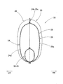
また、バッグ本体33は、図5,8〜10に示すように、膨張完了時に締結部位P付近と乗員MPとの間に介在されるバックルカバー部38と、膨張完了時にバックルカバー部38から前方に延びるように配置される前側膨張部39と、膨張完了時にバックルカバー部38から後上方に延びるように配置される後側膨張部42と、を備えている。すなわち、前側膨張部39は、膨張完了時に締結部位P付近の内側に配置されるバックルカバー部38を経て前方に延びるように配置され、後側膨張部42は、締結部位P付近の内側に配置されるバックルカバー部38を経て後方に延びるように配置されている。実施形態の場合、バッグ本体33は、乗員側壁部34と離隔側壁部35とを重ねるように平らに展開した状態において、図5に示すように、扁平な楕円状として、前後の中間部位付近の上縁側を僅かに凹ませつつ、かつ、後側の領域を、後上がりに傾斜させつつ屈曲させるような、「空豆」に近似した外形形状とされている。そして、乗員側壁部34と離隔側壁部35とを重ねるように平らに展開した状態のバッグ本体33において、前後方向に略沿って配置される前側の領域が、前側膨張部39を構成し、前後の中間部位付近の上縁側を凹ませている部位が、バックルカバー部38を構成し、後上がりに傾斜している後側の領域が、後側膨張部42を構成している。すなわち、乗員側壁部34と離隔側壁部35とにおいて、バックルカバー部38を構成する前後の中間部位34a,35aは、上縁34b,35b側を下方に凹ませるような凹部34c,35cを、備えている(図7参照)。
Further, as shown in FIGS. 5 and 8 to 10, the bag
そして、実施形態のバッグ本体33では、膨張完了時に、前側膨張部39は、助手席PSに着座した乗員MPの下半身において、腰部MWから大腿部MTにかけての右側を覆い、後側膨張部42は、助手席PSに着座した乗員MPの上半身において、腰部MWから胸部MBにかけての右側を覆うこととなる(図8参照)。さらに詳細には、前側膨張部39は、膨張完了時の前端39aを、助手席PSの座部4の前端4aよりも後方であって、前後の中央より前側に位置させるように、構成され、後側膨張部42は、膨張完了時の上端42aを、背もたれ部8における上下の中央付近に位置させるように、構成されている。また、バックルカバー部38は、乗員側壁部34と離隔側壁部35との上縁34b,35bを部分的に下方に凹ませることにより、膨張完了時に、前後両側に配置される前側膨張部39,後側膨張部42よりも凹ませるように(膨張完了時の断面積を小さくして)、構成されている(図6参照)。
In the bag
そして、実施形態のエアバッグ装置25では、車両Vがバックル部19側となる斜め右前方から衝撃力を作用させるような斜突時において、乗員MPが右斜め前方に向かって移動した際に、バッグ本体33が、乗員MPにより押される後側膨張部42を、締結部位P付近を跨いで、前側膨張部39の右側面側に接触させるように、折り重ねて配置可能に、構成されている(図11〜13参照)。すなわち、後側膨張部42は、後上がりに傾斜している軸方向に略沿った長さ寸法を、締結部位P付近の部位で折り曲げた際に、先端(上端42a)側を、前側膨張部39に接触可能な寸法に、設定されている。そして、後側膨張部42は、この先端(上端42a)側の部位を、折り重ね時に、前側膨張部39に当接される当接部43としている。また、前側膨張部39において、バックルカバー部38に近接した後側の領域が、後側膨張部42の当接部43を支持可能な支持部40とされている(図11〜13参照)。
And, in the
また、実施形態のバッグ本体33には、図5に示すように、バックルカバー部38の下縁側に、インフレーター26に接続される筒状の接続口部45が、バッグ本体33から斜め後下方に突出するように、形成されている。接続口部45は、先端45a側を、インフレーター26の本体27を挿入可能に開口させて構成されるもので、外周側に配置させたクランプ30を利用して、インフレーター26の本体27と接続される構成である。
Further, as shown in FIG. 5, the bag
バッグ本体33内に配置されるインナチューブ48は、図5,6に示すように、接続口部45内に配置されてインフレーター26から吐出される膨張用ガスGを案内する導管部49と、導管部49の先端側に配置されて膨張用ガスGを前後に分岐させる本体部50と、を備えている。本体部50は、前後両端側を開口させた略筒状として構成されるもので、膨張完了時のバッグ本体33の下端側において、前後方向に略沿って配置されている。具体的には、本体部50は、バックルカバー部38の内径寸法の半分以下(実施形態の場合、1/3程度)の小さな内径寸法として、締結部位P付近の内部を跨ぐようにバックルカバー部38内を横切って、前端50a側と後端50b側とを、それぞれ、前側膨張部39と後側膨張部42との領域内に配置させて、インフレーター26から吐出される膨張用ガスGを、バックルカバー部38内を経て、前端50a側と後端50b側との開口51,52から、前側膨張部39側と後側膨張部42側とに案内するように、構成されている(図5参照)。詳細には、本体部50における前端50a,後端50b(開口51,52)は、それぞれ、バックルカバー部38から前方あるいは後方に離れた位置に、配置されている。導管部49は、接続口部45の内周側を略全域にわたって覆うような筒状として、構成されている。そして、実施形態の場合、インナチューブ48は、図7に示すように、可撓性を有した織布からなる外形形状を同一とした2枚のインナチューブ用素材53,53から構成されている。そして、インナチューブ48は、このインナチューブ用素材53における本体部50を構成する部位の上縁相互を結合(縫着)させた状態で、未結合の状態の本体部50の下縁側から導管部49の前縁側若しくは後縁側にかけての領域を、バッグ本体33の製造時に、乗員側壁部34,離隔側壁部35の外周縁と共縫いすることにより、筒状に形成されるとともに、バッグ本体33に連結されている。
As shown in FIGS. 5 and 6, the
また、実施形態の乗員保護装置Sを搭載させた車両Vにおいて、助手席PSの前方となるインストルメントパネル(以下「インパネ」と省略する)1の下方の領域には、車両Vの前方側からの衝撃力作用時に作動する助手席用のエアバッグ装置55が、配置されている(図1参照)。このエアバッグ装置55は、インパネ1の下面側に折り畳まれて収納されるエアバッグ56と、エアバッグ56に膨張用ガスを供給する図示しないインフレーターと、を備え、エアバッグ56は、斜突時も含めて前方からの衝撃力の作用時に、内部に膨張用ガスを流入させて、助手席PSの前方を広く覆うように膨張することとなる(図8,10の二点鎖線参照)。
Further, in the vehicle V on which the occupant protection device S of the embodiment is mounted, a region below the instrument panel (hereinafter abbreviated as “instrument panel”) 1 in front of the passenger seat PS is located from the front side of the vehicle V.
実施形態の乗員保護装置Sでは、助手席PSに着座した乗員MPがシートベルト装置15を装着した状態で、車両Vの右側RWや右斜め前方から図示しない衝突物が衝突した側面衝突時に、作動回路からの作動信号を受けて、シートベルト装置15のプリテンショナー機構21がウェビング17を引き込むように作動し、エアバッグ装置25のインフレーター26が作動することとなる。そして、エアバッグ32が、内部に膨張用ガスを流入させて膨張し、図8〜10に示すように、シートベルト装置15におけるラップベルト部17b及びショルダーベルト部17aと乗員MPとの間で、乗員MPの右側RWを覆うように膨張を完了させることとなる。また、車両Vの右斜め前方から図示しない衝突物が衝突した際には、助手席PSの前方に配置されるエアバッグ装置55も、図8,10の二点鎖線に示すように、エアバッグ56を膨張させるように作動されることとなる。
In the occupant protection device S of the embodiment, the occupant MP seated in the passenger seat PS operates in a side collision where a collision object (not shown) collides from the right side RW or right front side of the vehicle V with the
そして、実施形態の乗員保護装置Sでは、エアバッグ装置25のエアバッグ32が、シートベルト装置15におけるラップベルト部17b及びショルダーベルト部17aと、助手席PSに着座した乗員MPと、の間で膨張を完了させる構成とされ、このエアバッグ32が、膨張完了時に、シートベルト装置15におけるバックル部19にタング18を締結させた締結部位P付近の内側を経て締結部位P付近から前方に延びる前側膨張部39と、締結部位P付近の内側を経て締結部位P付近から後上方に延びる後側膨張部42と、を、を有する構成とされている。そして、車両Vに、バックル部19側前方となる右斜め前方から衝撃力が作用した斜突時に、乗員MPが右斜め前方に向かって前方移動すると、この乗員MPの前方移動に伴って、図11,12に示すように、後側膨張部42が前側に押されることとなるが、実施形態の乗員保護装置Sでは、後側膨張部42は、図13に示すように、締結部位P付近を跨ぐようにして、前側膨張部39に接触されることとなる。すなわち、実施形態の乗員保護装置Sでは、斜突時に、乗員MPの上半身を受け止めた後側膨張部42が、シートベルト装置15における締結部位P付近を間に介在させつつ、前側膨張部39に折り重なって配置されることから、エアバッグ32(バッグ本体33)自体が締結部位P付近からすり抜けるように移動することを抑制できる。また、実施形態の乗員保護装置Sでは、この接触時(折り重ね時)に、図11〜13に示すように、後側膨張部42に配置される当接部43が、前側膨張部39に形成される支持部40に支持されることとなる。そのため、当接部43を支持部40に支持させるようにして、折り重なって厚く膨張しているエアバッグ32の後側膨張部42と前側膨張部39とによって、乗員MPの腰部MWを的確に拘束することができ、乗員MPのさらなる前方移動を抑制することができる。その結果、乗員MPが右斜め前方に向かって大きく移動することを抑制できて、座部4近傍に配置されるバックル部19から車内外方向の外側となる左側LW上方に向かって延びるシートベルト装置15のショルダーベルト部17aからすり抜けるように移動することを的確に防止できる。
In the occupant protection device S of the embodiment, the
したがって、実施形態の乗員保護装置では、シートベルト装置15におけるバックル部19の前方(右斜め前方)から衝撃力が作用する斜突時にも、膨張したエアバッグ32によって、乗員MPを的確に保護することができる。
Therefore, in the occupant protection device according to the embodiment, the occupant MP is accurately protected by the
そして、右斜め前方からの斜突時には、図8,10の二点鎖線に示すように、助手席PSの前方に搭載されるエアバッグ装置55も作動されてエアバッグ56が膨張していることから、実施形態の乗員保護装置Sを搭載した車両Vでは、エアバッグ32によって右側RWへの移動量を抑制され、シートベルト装置15による拘束を維持された状態の乗員MPを、助手席PSの前方で膨張しているエアバッグ56によって、的確に受け止めることができる(図12の二点鎖線参照)。
At the time of oblique projection from the right front, the
また、実施形態の乗員保護装置Sでは、エアバッグ32(バッグ本体33)は、膨張完了時に締結部位P付近から前方に延びる前側膨張部39と、締結部位P付近から後上方に延びる後側膨張部42と、を有し、膨張完了時に、助手席PSに着座した乗員MPの右側RWを広く覆う構成であることから(図8参照)、車両Vの右方から衝撃力が作用する側面衝突時にも、乗員MPの右側RWにおいて運転席DSとの間に配置されるコンソールボックス2(図8〜10参照)等の部材と乗員MPが干渉することを抑制できて、乗員MPを的確に保護することができる。
In the occupant protection device S of the embodiment, the airbag 32 (bag body 33) includes a front inflating
さらに、実施形態の乗員保護装置Sでは、エアバッグ32(バッグ本体33)内に、インフレーター26から吐出される膨張用ガスGを、締結部位P付近の内側を経て、前側膨張部39側と後側膨張部42側とに案内可能なインナチューブ48を、配置させている。そのため、前側膨張部39と後側膨張部42とを迅速に膨張させることができて、エアバッグ32を、ラップベルト部17b及びショルダーベルト部17aと、乗員MPと、の間に、広く迅速に展開させることができる。特に、実施形態の乗員保護装置Sでは、インフレーター26の作動開始を、シートベルト装置15のプリテンショナー機構21の作動開始より、僅かに遅らせて、プリテンショナー機構21によるウェビング17の引き込み開始後に、インフレーター26が作動される構成であることから、ラップベルト部17b及びショルダーベルト部17aと、乗員MPと、の間の隙間が、一層狭くなるが、この狭い隙間に入り込んだバッグ本体33のインナチューブ48が、締結部位P(ラップベルト部17b、ショルダーベルト部17a、及び、バックル部19)から前後で離れた位置に配置される前後両端側の開口51,52から、前側膨張部39,後側膨張部42側に、膨張用ガスGを円滑に流出させることができる(図8参照)。そのため、プリテンショナー機構21を作動させて、締結部位P(ラップベルト部17b、ショルダーベルト部17a、及び、バックル部19)と、乗員MPと、の間の隙間が狭くなっていても、エアバッグ32を支障なく膨張させることができる。なお、このような点を考慮しなければ、エアバッグとして、インナチューブを配置させない構成の物を使用してもよい。
Further, in the occupant protection device S of the embodiment, the inflation gas G discharged from the inflator 26 into the airbag 32 (bag body 33) passes through the inside of the vicinity of the fastening portion P, and the front inflating
さらにまた、実施形態の乗員保護装置Sでは、インフレーター26を、シートベルト装置15のプリテンショナー機構21の作動開始より、作動開始を僅かに遅らせるように設定している。すなわち、実施形態の乗員保護装置Sでは、プリテンショナー機構21の作動によりウェビング17がある程度引き込まれた状態で、エアバッグ32が膨張することから、膨張するエアバッグ32に押圧されてウェビング17が引き出されることを抑制できる。また、膨張したエアバッグの上からシートベルト装置のラップベルト部を牽引して乗員の腰部に接近させる状態ではなく、シートベルト装置15のラップベルト部17bを、乗員MPの腰部MWに接触させるように配置させた状態で、エアバッグ32を所定形状に膨張させることができる。そのため、膨張完了時のエアバッグ32(バッグ本体33)が、ラップベルト部17bを、乗員MPの腰部MWから上方に離れるように押し上げることを防止でき、ラップベルト部17bと乗員MPとの間に大きな隙間が生じがたい。このような点を考慮しなければ、インフレーターを、プリテンショナー機構と略同時、あるいは、先行して作動させる構成としてもよい。
Furthermore, in the occupant protection device S of the embodiment, the
さらにまた、実施形態の乗員保護装置Sにおいて、エアバッグ32(バッグ本体33)において、膨張完了時に、締結部位P付近と乗員MPとの間に介在される部位であるバックルカバー部38を、前後両側の膨張部位である前側膨張部39及び後側膨張部42より凹ませるように、構成していることから、締結部位P付近と乗員MPとの間に介在されるバックルカバー部38が、膨張完了時の断面積を小さく設定されることとなり、エアバッグ32の膨張完了時に、エアバッグ32によってラップベルト部17bが押し上げられることを、一層抑制でき、かつ、後側膨張部42を前側膨張部39に接触させる際に、バックルカバー部38を起点として曲げやすく、後側膨張部42を前側膨張部39に折り重ねるような配置が容易となる。
Furthermore, in the occupant protection device S of the embodiment, when the airbag 32 (bag main body 33) is inflated, the
具体的には、実施形態の乗員保護装置Sでは、エアバッグ32のバッグ本体33を構成する乗員側壁部34と離隔側壁部35が、バックルカバー部38を構成する中間部位34a,35aの上縁34b,35b側を凹ませるように、構成されて、膨張完了時のエアバッグ32におけるバックルカバー部38を、前後両側の前側膨張部39,後側膨張部42よりも上下方向側の幅寸法を縮められるようにして、断面積を小さくしている。
Specifically, in the occupant protection device S of the embodiment, the occupant
また、エアバッグ32Aとして、図14,15に示すように、バッグ本体33Aにおけるバックルカバー部38Aの内部に、乗員側壁部34Aと離隔側壁部35Aとの離隔距離を規制するテザー60を配置させた構成のものを使用してもよい。図14,15に示すエアバッグ32Aは、乗員側壁部34Aと離隔側壁部35Aとの外形形状を若干異ならせて、内部にテザー60を配置させている以外は、上述のエアバッグと同様の構成であることから、同一の部材には、同一の図符号の末尾に「A」を付して詳細な説明を省略する。バッグ本体33Aを構成する乗員側壁部34Aと離隔側壁部35Aとは、外形形状を同一として構成され、上述のエアバッグ32における乗員側壁部34及び離隔側壁部35と相違して、上縁34b,35bを略直線状として、構成されている。また、バッグ本体33Aにおいて、バックルカバー部38Aの部位には、可撓性を有した帯状のシート材から構成されるテザー60が、乗員側壁部34Aと離隔側壁部35Aとを連結するように、配置されている。このテザー60は、膨張完了時の乗員側壁部34Aと離隔側壁部35Aとの離隔距離を規制して、バックルカバー部38Aを、前後の前側膨張部39A,後側膨張部42Aより薄く膨張させるためのもので、実施形態の場合、テザー60は、バックルカバー部38Aにおけるインナチューブ48Aの上方の領域において、上下方向に略沿うようにして、配置されている。このような構成のエアバッグ32Aでは、膨張完了時において、バックルカバー部38Aが、前後両側の前側膨張部39A,後側膨張部42Aよりも厚さ寸法を縮められるようにして、断面積を小さくされることとなる。
Further, as shown in FIGS. 14 and 15, as the
なお、実施形態では、助手席に搭載される乗員保護装置を例に採り説明したが、勿論、本発明の乗員保護装置は、運転席に搭載させてもよい。 In the embodiment, the occupant protection device mounted on the passenger seat has been described as an example, but of course, the occupant protection device of the present invention may be mounted on the driver seat.
また、実施形態では、エアバッグ装置のエアバッグを、助手席における座部のバックル部近傍となる位置に収納させているが、エアバッグの収納部位はこれに限られるものではなく、バックル部自体に折り畳まれたエアバッグを収納させる構成としてもよい。さらに、実施形態では、シートベルト装置として、三点式のものを例に採り説明したが、本発明に使用可能なシートベルト装置は、三点式に限られるものではなく、装着時に、ショルダーベルト部とラップベルト部との間の部位をバックル部に締結させる構成であれば、四点式のシートベルト装置を使用してもよい。 In the embodiment, the airbag of the airbag device is stored in a position near the buckle portion of the seat portion in the passenger seat, but the storage portion of the airbag is not limited to this, and the buckle portion itself It is good also as a structure which accommodates the airbag folded in. Furthermore, in the embodiment, the three-point type of seat belt device has been described as an example. However, the seat belt device usable in the present invention is not limited to the three-point type, and the shoulder belt portion and the lap belt can be used when worn. A four-point seat belt device may be used as long as it is configured to fasten the portion between the two portions to the buckle portion.
4…座部、15…シートベルト装置、16…ベルト部、17…ウェビング、17a…ショルダーベルト部、17b…ラップベルト部、18…タング、19…バックル部、21…プリテンショナー機構、25…エアバッグ装置、26…インフレーター、32,32A…エアバッグ、33,33A…バッグ本体、34、34A…乗員側壁部、34c…凹部、35,35A…離隔側壁部、35c…凹部、38,38A…バックルカバー部、39,39A…前側膨張部、40…支持部、42,42A…後側膨張部、43…当接部、45…接続口部、48,48A…インナチューブ、51,52…開口、60…テザー、P…締結部位、PS…助手席(座席)、MP…乗員、V…車両、S…乗員保護装置。
DESCRIPTION OF
Claims (7)
前記エアバッグ装置が、内部に膨張用ガスを流入させて前記シートベルト装置におけるラップベルト部及びショルダーベルト部と前記シートに着座した乗員との間の部位で膨張するエアバッグと、該エアバッグに膨張用ガスを供給するインフレーターと、を、備え、
前記エアバッグが、
前記締結部位付近と前記乗員との間に介在されるバックルカバー部と、膨張完了時に前記締結部位付近の内側に配置される前記バックルカバー部を経て前方に延びるように配置される前側膨張部と、膨張完了時に前記締結部位付近の内側に配置される前記バックルカバー部を経て後上方に延びるように配置される後側膨張部と、を備えるとともに、
前記バックル部側前方となる斜め前方から衝撃力が作用した際の前記乗員の前方移動時に、前記乗員により押される前記後側膨張部を、前記締結部位付近を跨いで、前記前側膨張部に接触可能に、構成され、
前記後側膨張部が、前記前側膨張部に当接される当接部を有し、
前記前側膨張部が、前記当接部を支持可能な支持部を、備えて構成され、
前記エアバッグ内に、前記インフレーターから吐出される膨張用ガスを、前記締結部位付近の内側を経て、前記前側膨張部側と前記後側膨張部側とに、案内可能な構成とされるインナチューブが、配置され、
該インナチューブが、前記バックルカバー部内を横切って配置されて、前後両端側を開口させた略筒状として構成され、前端側と後端側とを、それぞれ、前記前側膨張部と前記後側膨張部との領域内に配置させるように構成されていることを特徴とする乗員保護装置。 An occupant protection device comprising: a seat belt device mounted on a vehicle seat; and an airbag device disposed in the vicinity of a fastening portion where a tongue is fastened to a buckle portion of the seat belt device in the seat,
An airbag that inflates at a portion between a lap belt portion and a shoulder belt portion of the seat belt device and an occupant seated on the seat by infusing inflation gas into the airbag device; and the airbag An inflator for supplying an inflation gas,
The airbag is
A buckle cover portion interposed between the vicinity of the fastening portion and the occupant, and a front side inflating portion disposed to extend forward through the buckle cover portion disposed inside the vicinity of the fastening portion when the inflation is completed A rear-side inflatable part arranged to extend rearward and upward through the buckle cover part arranged inside the vicinity of the fastening part when the inflation is completed, and
When the occupant moves forward when an impact force acts obliquely from the front side of the buckle portion side, the rear inflatable portion pushed by the occupant straddles the vicinity of the fastening portion and contacts the front inflatable portion. Possible, configured,
The rear expansion part has an abutting part abutted on the front expansion part;
The front expansion portion is configured to include a support portion that can support the contact portion ,
An inner tube configured to be able to guide the inflation gas discharged from the inflator into the airbag toward the front and rear inflating parts through the inside of the vicinity of the fastening portion. Is placed,
The inner tube is disposed across the buckle cover part and is configured as a substantially cylindrical shape with both front and rear ends opened, and the front end side and the rear end side are respectively connected to the front side expansion part and the rear side expansion part. An occupant protection device configured to be disposed in a region with a section .
前記エアバッグ装置が、内部に膨張用ガスを流入させて前記シートベルト装置におけるラップベルト部及びショルダーベルト部と前記シートに着座した乗員との間の部位で膨張するエアバッグと、該エアバッグに膨張用ガスを供給するインフレーターと、を、備え、
前記エアバッグが、
前記締結部位付近と前記乗員との間に介在されるバックルカバー部と、膨張完了時に前記締結部位付近の内側に配置される前記バックルカバー部を経て前方に延びるように配置される前側膨張部と、膨張完了時に前記締結部位付近の内側に配置される前記バックルカバー部を経て後上方に延びるように配置される後側膨張部と、を備えるとともに、
前記バックル部側前方となる斜め前方から衝撃力が作用した際の前記乗員の前方移動時に、前記乗員により押される前記後側膨張部を、前記締結部位付近を跨いで、前記前側膨張部に接触可能に、構成され、
前記後側膨張部が、前記前側膨張部に当接される当接部を有し、
前記前側膨張部が、前記当接部を支持可能な支持部を、備えて構成され、
前記エアバッグが、前記バックルカバー部の下縁から斜め後下方に突出するように形成されて、前記インフレーターと接続される筒状の接続口部を、備えていることを特徴とする乗員保護装置。 An occupant protection device comprising: a seat belt device mounted on a vehicle seat; and an airbag device disposed in the vicinity of a fastening portion where a tongue is fastened to a buckle portion of the seat belt device in the seat,
An airbag that inflates at a portion between a lap belt portion and a shoulder belt portion of the seat belt device and an occupant seated on the seat by infusing inflation gas into the airbag device; and the airbag An inflator for supplying an inflation gas,
The airbag is
A buckle cover portion interposed between the vicinity of the fastening portion and the occupant, and a front side inflating portion disposed to extend forward through the buckle cover portion disposed inside the vicinity of the fastening portion when the inflation is completed A rear-side inflatable part arranged to extend rearward and upward through the buckle cover part arranged inside the vicinity of the fastening part when the inflation is completed, and
When the occupant moves forward when an impact force acts obliquely from the front side of the buckle portion side, the rear inflatable portion pushed by the occupant straddles the vicinity of the fastening portion and contacts the front inflatable portion. Possible, configured,
The rear expansion part has an abutting part abutted on the front expansion part;
The front expansion portion is configured to include a support portion that can support the contact portion ,
The occupant protection device characterized in that the airbag includes a cylindrical connection port portion that is formed so as to protrude obliquely rearward and downward from the lower edge of the buckle cover portion and is connected to the inflator. .
前記インフレーターが、前記プリテンショナー機構の作動開始より、作動開始を遅らせるように設定されていることを特徴とする請求項1乃至3のいずれか1項に記載の乗員保護装置。 The seat belt device includes a pretensioner mechanism,
The occupant protection device according to any one of claims 1 to 3, wherein the inflator is set so as to delay the operation start from the operation start of the pretensioner mechanism.
前記乗員側壁部と前記離隔側壁部とが、前記締結部位付近と前記乗員との間に介在される部位の外周縁を凹ませるように、構成されて、前記バックルカバー部の凹み形状を形成していることを特徴とする請求項5に記載の乗員保護装置。 The airbag is configured to have substantially the same outer shape, and an outer peripheral edge between an occupant side wall portion disposed on the occupant side upon completion of inflation and a separated side wall portion disposed on a side separated from the occupant. Composed of
The occupant side wall portion and the separated side wall portion are configured to dent an outer peripheral edge of a portion interposed between the vicinity of the fastening portion and the occupant, and form a dent shape of the buckle cover portion. The occupant protection device according to claim 5 .
膨張完了時に前記乗員側に配置される乗員側壁部と、前記乗員から離隔した側に配置される離隔側壁部と、の外周縁相互を結合させて構成されるとともに、
前記締結部位付近と前記乗員との間に介在される部位の内部に、前記乗員側壁部と前記離隔側壁部との離隔距離を規制するテザーを、配置させて、前記バックルカバー部の凹み形状を形成していることを特徴とする請求項5に記載の乗員保護装置。 The airbag is
The occupant side wall portion disposed on the occupant side at the completion of the inflation and the separated side wall portion disposed on the side separated from the occupant are configured by coupling the outer peripheral edges of each other,
A tether that regulates a separation distance between the occupant side wall portion and the separation side wall portion is disposed inside a portion interposed between the vicinity of the fastening portion and the occupant, so that a concave shape of the buckle cover portion is formed. The occupant protection device according to claim 5 , wherein the occupant protection device is formed.
Priority Applications (2)
| Application Number | Priority Date | Filing Date | Title |
|---|---|---|---|
| JP2013204270A JP5979111B2 (en) | 2013-09-30 | 2013-09-30 | Crew protection device |
| US14/473,258 US9233661B2 (en) | 2013-09-30 | 2014-08-29 | Occupant protection system |
Applications Claiming Priority (1)
| Application Number | Priority Date | Filing Date | Title |
|---|---|---|---|
| JP2013204270A JP5979111B2 (en) | 2013-09-30 | 2013-09-30 | Crew protection device |
Publications (2)
| Publication Number | Publication Date |
|---|---|
| JP2015067181A JP2015067181A (en) | 2015-04-13 |
| JP5979111B2 true JP5979111B2 (en) | 2016-08-24 |
Family
ID=52739369
Family Applications (1)
| Application Number | Title | Priority Date | Filing Date |
|---|---|---|---|
| JP2013204270A Active JP5979111B2 (en) | 2013-09-30 | 2013-09-30 | Crew protection device |
Country Status (2)
| Country | Link |
|---|---|
| US (1) | US9233661B2 (en) |
| JP (1) | JP5979111B2 (en) |
Families Citing this family (8)
| Publication number | Priority date | Publication date | Assignee | Title |
|---|---|---|---|---|
| US9821761B2 (en) * | 2015-11-20 | 2017-11-21 | Ford Global Technologies, Llc | System and method for webbing payout |
| US10407015B2 (en) * | 2017-06-27 | 2019-09-10 | Ford Global Technologies, Llc | Restraint system |
| US10471919B2 (en) * | 2017-07-21 | 2019-11-12 | Ford Global Technologies, Llc | Vehicle airbag system |
| US20190061581A1 (en) * | 2017-08-25 | 2019-02-28 | GM Global Technology Operations LLC | Seat Shell Formed by Additive Manufacturing |
| KR102518180B1 (en) * | 2017-12-08 | 2023-04-07 | 현대자동차주식회사 | Air bag for vehicle |
| JP6762328B2 (en) * | 2018-02-14 | 2020-09-30 | オートリブ ディベロップメント エービー | Crew restraint device |
| US10889257B2 (en) * | 2019-02-27 | 2021-01-12 | Ford Global Technologies, Llc | Vehicle seat assembly |
| US11167714B2 (en) * | 2019-11-08 | 2021-11-09 | Honda Motor Co., Ltd. | Occupant restraint system for a vehicle |
Family Cites Families (29)
| Publication number | Priority date | Publication date | Assignee | Title |
|---|---|---|---|---|
| DE2260366A1 (en) * | 1972-12-09 | 1974-07-04 | Braun Ag | SAFETY DEVICE FOR MOTOR VEHICLES, IN PARTICULAR FOR THE PROTECTION OF CHILDREN AND YOUNG PEOPLE |
| US5465999A (en) * | 1994-06-30 | 1995-11-14 | Takata Corporation | Inflatable seat belt having defined shape |
| US5630616A (en) * | 1996-02-14 | 1997-05-20 | Lear Seating Corporation | Seat frame integrated air bag inflator |
| US6293582B1 (en) * | 1996-06-14 | 2001-09-25 | Universal Propulsion Company, Inc. | Control system for air bags in different vehicle locations |
| DE19725558C2 (en) * | 1997-06-12 | 2001-11-29 | Petri Ag | Airbag restraint system |
| US6378898B1 (en) * | 1999-06-09 | 2002-04-30 | The B.F. Goodrich Company | Inflatable air bag for an inflatable restraint system |
| JP2001247010A (en) * | 1999-12-28 | 2001-09-11 | Takata Corp | Occupant protective device |
| US6382666B1 (en) * | 2000-03-13 | 2002-05-07 | Universal Propulsion Company, Inc. | Arrangement for providing deployment of inflatable member coaxially with safety belt portion and related method |
| US6705641B2 (en) * | 2002-03-08 | 2004-03-16 | Autoliv Asp, Inc. | Inflatable seat belt system |
| JP2004330903A (en) * | 2003-05-08 | 2004-11-25 | Nissan Motor Co Ltd | Side airbag device of automobile |
| JP4609056B2 (en) * | 2004-12-07 | 2011-01-12 | 日産自動車株式会社 | Occupant protection device and occupant protection method |
| JP2006281967A (en) * | 2005-03-31 | 2006-10-19 | Nippon Plast Co Ltd | Airbag device |
| JP4645280B2 (en) * | 2005-04-18 | 2011-03-09 | 日産自動車株式会社 | Occupant protection device and method |
| JP4735078B2 (en) * | 2005-06-28 | 2011-07-27 | タカタ株式会社 | Occupant restraint belt and occupant restraint device |
| JP4923531B2 (en) * | 2005-11-15 | 2012-04-25 | タカタ株式会社 | Air belt device |
| JP4917323B2 (en) * | 2006-02-24 | 2012-04-18 | 豊田合成株式会社 | Crew protection device |
| US20080061538A1 (en) * | 2006-09-11 | 2008-03-13 | Trw Vehicle Safety Systems Inc. | Inflatable vehicle occupant protection device for inboard pelvis protection |
| JP2008143273A (en) | 2006-12-07 | 2008-06-26 | Toyoda Gosei Co Ltd | Vehicular occupant crash protector |
| JP4946444B2 (en) | 2007-01-04 | 2012-06-06 | 豊田合成株式会社 | Crew protection device |
| JP2008296722A (en) * | 2007-05-31 | 2008-12-11 | Toyoda Gosei Co Ltd | Occupant protection device |
| US7862081B2 (en) * | 2008-10-09 | 2011-01-04 | Gm Global Technology Operations, Inc. | Motor vehicle safety restraint system |
| JP2011005910A (en) * | 2009-06-24 | 2011-01-13 | Toyota Motor Corp | Seat belt device |
| JP2011025909A (en) * | 2009-07-03 | 2011-02-10 | Toyoda Gosei Co Ltd | Side airbag device |
| JP2011140246A (en) * | 2010-01-05 | 2011-07-21 | Toyota Motor Corp | Side airbag device |
| DE102011000052A1 (en) | 2010-01-08 | 2011-07-28 | TK Holdings, Inc., Mich. | air bag |
| US8282126B2 (en) * | 2010-10-13 | 2012-10-09 | Tk Holdings Inc. | Occupant restraint system |
| CN103313881B (en) * | 2010-10-28 | 2016-04-20 | 关键安全体系股份有限公司 | Single retractor inflatable belt system |
| US8672347B2 (en) * | 2012-04-09 | 2014-03-18 | Autoliv Asp, Inc. | Integrated airbag restraint |
| US8882138B1 (en) * | 2014-03-26 | 2014-11-11 | Autoliv Asp, Inc. | Center airbag |
-
2013
- 2013-09-30 JP JP2013204270A patent/JP5979111B2/en active Active
-
2014
- 2014-08-29 US US14/473,258 patent/US9233661B2/en active Active
Also Published As
| Publication number | Publication date |
|---|---|
| US20150091283A1 (en) | 2015-04-02 |
| US9233661B2 (en) | 2016-01-12 |
| JP2015067181A (en) | 2015-04-13 |
Similar Documents
| Publication | Publication Date | Title |
|---|---|---|
| JP5979111B2 (en) | Crew protection device | |
| JP6673392B2 (en) | Occupant protection device | |
| JP6380348B2 (en) | Crew protection device | |
| US9132798B2 (en) | Seat-mounted airbag apparatus and vehicle seat | |
| JP5853916B2 (en) | Airbag device | |
| JP6492366B2 (en) | Vehicle occupant restraint system | |
| JP2017185873A (en) | Occupant protection apparatus | |
| JP4924667B2 (en) | Crew restraint system | |
| JP2010126141A (en) | Occupant restraint system for vehicle | |
| JP2010083384A (en) | Occupant restraint system | |
| JP2000142303A (en) | Air bag device for head protection | |
| WO2010055705A1 (en) | Occupant restraint device for vehicles | |
| JP2019147426A (en) | Vehicle occupant protection device | |
| JP2023068526A (en) | Vehicle seat and method for folding side airbag | |
| JP4687300B2 (en) | Crew restraint system | |
| JP6499093B2 (en) | Crew protection device | |
| JP6499096B2 (en) | Crew protection device | |
| JP5244751B2 (en) | Vehicle occupant restraint system | |
| JP6329051B2 (en) | Airbag device | |
| JP2022110958A (en) | Vehicular side airbag device | |
| JP2011005910A (en) | Seat belt device | |
| JP2007125937A (en) | Air belt device for vehicle | |
| JP2005125997A (en) | Seat belt provided with air bag | |
| US20240253590A1 (en) | Vehicle occupant restraint device | |
| CN114379500B (en) | Occupant protection device for vehicle |
Legal Events
| Date | Code | Title | Description |
|---|---|---|---|
| A621 | Written request for application examination |
Free format text: JAPANESE INTERMEDIATE CODE: A621 Effective date: 20150925 |
|
| A977 | Report on retrieval |
Free format text: JAPANESE INTERMEDIATE CODE: A971007 Effective date: 20160128 |
|
| A131 | Notification of reasons for refusal |
Free format text: JAPANESE INTERMEDIATE CODE: A131 Effective date: 20160202 |
|
| A521 | Written amendment |
Free format text: JAPANESE INTERMEDIATE CODE: A523 Effective date: 20160330 |
|
| TRDD | Decision of grant or rejection written | ||
| A01 | Written decision to grant a patent or to grant a registration (utility model) |
Free format text: JAPANESE INTERMEDIATE CODE: A01 Effective date: 20160628 |
|
| A61 | First payment of annual fees (during grant procedure) |
Free format text: JAPANESE INTERMEDIATE CODE: A61 Effective date: 20160711 |
|
| R150 | Certificate of patent (=grant) or registration of utility model |
Ref document number: 5979111 Country of ref document: JP Free format text: JAPANESE INTERMEDIATE CODE: R150 |