JP5975673B2 - Switch operating device and electronic device - Google Patents
Switch operating device and electronic device Download PDFInfo
- Publication number
- JP5975673B2 JP5975673B2 JP2012040021A JP2012040021A JP5975673B2 JP 5975673 B2 JP5975673 B2 JP 5975673B2 JP 2012040021 A JP2012040021 A JP 2012040021A JP 2012040021 A JP2012040021 A JP 2012040021A JP 5975673 B2 JP5975673 B2 JP 5975673B2
- Authority
- JP
- Japan
- Prior art keywords
- lever
- switch
- click
- exterior cover
- state
- Prior art date
- Legal status (The legal status is an assumption and is not a legal conclusion. Google has not performed a legal analysis and makes no representation as to the accuracy of the status listed.)
- Expired - Fee Related
Links
Images


Landscapes
- Camera Bodies And Camera Details Or Accessories (AREA)
- Switch Cases, Indication, And Locking (AREA)
- Rotary Switch, Piano Key Switch, And Lever Switch (AREA)
Description
本発明は、操作部材を介してレバースイッチのレバー部を作動させるスイッチ操作装置、及びスイッチ操作装置を備えるデジタルカメラ等の電子機器に関する。 The present invention relates to a switch operation device that operates a lever portion of a lever switch via an operation member, and an electronic device such as a digital camera including the switch operation device.
デジタルカメラ等の電子機器では、操作部材を回動操作してレバースイッチのレバー部を作動させ、レバー部の作動をレバースイッチで検知することでスイッチングを行うスイッチ操作装置を備えるものがある。 Some electronic devices such as a digital camera include a switch operation device that performs switching by operating a lever portion of a lever switch by rotating an operation member and detecting the operation of the lever portion with the lever switch.
従来のこの種のスイッチ操作装置としては、レバースイッチのレバー部を作動させる操作部材の一部を弾性部材で形成したものが提案されている(特許文献1)。 As a conventional switch operating device of this type, a device in which a part of an operating member that operates a lever portion of a lever switch is formed of an elastic member has been proposed (Patent Document 1).
この提案では、スイッチ操作装置の組立時に操作部材の一部がレバースイッチのレバー部と干渉してレバー部を作動方向と異なる方向に押しても、弾性部材が弾性変形することでレバースイッチの破損を防ぐことができるとしている。 In this proposal, even when a part of the operating member interferes with the lever part of the lever switch when the switch operating device is assembled and the lever part is pushed in a direction different from the operating direction, the elastic member is elastically deformed to damage the lever switch. It can be prevented.
しかし、上記特許文献1では、レバースイッチのレバー部は、弾性部材により作動方向と異なる方向に押された場合に、弾性部材が弾性変形する際の反力に対して十分な強度を有する必要があるため、使用できるレバースイッチの種類が限定されてしまう。
However, in
また、操作部材は、操作性の観点からある程度の強度が必要なため、操作部材の本体部分と弾性部材とを別々に形成して、本体部分に弾性部材を取り付けることになる。このため、部品点数が増加して、スイッチ操作装置の組立作業性が低下するとともに、コスト高を招く原因になる。 In addition, since the operation member needs a certain level of strength from the viewpoint of operability, the main body portion and the elastic member of the operation member are separately formed, and the elastic member is attached to the main body portion. For this reason, the number of parts increases, and the assembling workability of the switch operating device is lowered, which causes a high cost.
そこで、本発明は、スイッチ操作装置の組立時にレバースイッチが破損するのを防ぐことができると共に、レバースイッチの種類が限定されることがなく、かつスイッチ操作装置の組立作業性の向上、及び低コスト化を図る仕組みを提供することを目的とする。 Therefore, the present invention can prevent the lever switch from being damaged when the switch operating device is assembled, the type of the lever switch is not limited, and the assembling workability of the switch operating device is improved. The purpose is to provide a mechanism for cost reduction.
上記目的を達成するために、本発明のスイッチ操作装置は、固定部材と、前記固定部材に固定され、レバー部が作動することで検知信号を出力するレバースイッチと、前記固定部材に回動操作可能に組み付けられ、クリック溝を有するとともに、前記回動操作により前記レバー部を作動方向に押し付けて作動させる操作片を有する操作部材と、前記操作部材の前記クリック溝に保持された状態で、前記操作部材とともに前記固定部材に組み付けられ、前記組み付け状態で前記固定部材に固定されるクリックばねと、を備え、前記操作片は、前記操作部材の回動操作方向に互いに離間して2つ設けられ、前記クリック溝に前記クリックばねが保持された状態で前記操作部材を前記固定部材に組み付ける際には、前記クリックばねと前記固定部材とが係合することで、前記操作片の位置が前記レバースイッチの前記レバー部の位置に対して前記回動操作方向に離れた位置で、前記レバー部の位置が2つの前記操作片の間となる位置か、一方の前記操作片の外側となる位置のいずれかとなるように、前記操作部材の組み付け位置を案内することを特徴とする。 In order to achieve the above object, a switch operating device according to the present invention includes a fixing member, a lever switch that is fixed to the fixing member and outputs a detection signal when the lever portion is operated, and a rotating operation to the fixing member. An operation member that can be assembled, has a click groove, has an operation piece that is operated by pressing the lever portion in the operation direction by the rotation operation, and is held in the click groove of the operation member, A click spring that is assembled to the fixing member together with the operation member, and is fixed to the fixing member in the assembled state, and two operation pieces are provided apart from each other in the rotation operation direction of the operation member. , when assembling the operating member to the fixed member in a state in which the click spring is held by the click groove, the fixing member and the click spring There Engaging, at the position where the position of the operating piece leaves the rotation operation direction with respect to the position of the lever portion of the lever switch, the position of the lever portion and between the two of the operation piece The assembly position of the operation member is guided so as to be either the position or the position outside one of the operation pieces .
本発明によれば、スイッチ操作装置の組立時にレバースイッチが破損するのを防ぐことができると共に、レバースイッチの種類が限定されることがなく、かつスイッチ操作装置の組立作業性の向上、及び低コスト化を図ることができる。 According to the present invention, the lever switch can be prevented from being damaged during the assembly of the switch operating device, the type of the lever switch is not limited, and the assembling workability of the switch operating device is improved. Cost can be reduced.
以下、本発明の実施形態の一例を図面を参照して説明する。 Hereinafter, an example of an embodiment of the present invention will be described with reference to the drawings.
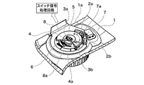
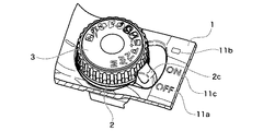
図1は本発明の電子機器の実施形態の一例であるデジタルカメラに取り付けられるスイッチ操作装置の斜視図、図2は図1に示すスイッチ操作装置を背面側から見た斜視図である。 FIG. 1 is a perspective view of a switch operation device attached to a digital camera as an example of an embodiment of an electronic apparatus according to the present invention. FIG. 2 is a perspective view of the switch operation device shown in FIG.
図1及び図2に示すように、本実施形態のスイッチ操作装置は、デジタルカメラのカメラ本体の上面部を形成する外装カバー1に取り付けられる。図1及び図2において、操作部材2の操作レバー2cは、ON表示11cの位置から図の矢印a又は矢印bの方向に回動操作可能に設けられている。すなわち、操作レバー2cをON表示11cの位置から図の矢印a方向に回動操作すると、OFF表示11a側に切り換えられ、図の矢印b方向に回動操作すると、□表示11b側に切り換えられる。また、操作レバー2cには、外装カバー1に形成された穴部1aを貫通して背面側に突出する2つの操作片2a,2bが操作レバー2cの回動操作方向に互いに離間して設けられている。ここで、外装カバー1は、本発明の固定部材の一例に相当する。
As shown in FIGS. 1 and 2, the switch operating device of the present embodiment is attached to an
操作ダイアル3は、デジタルカメラの各種モードを設定する為のダイアルであり、操作レバー2cと同様に、図の矢印a又は矢印bの方向に回転操作可能に設けられている。操作ダイアル3の上面には、各モードのアイコンが印刷されている。また、操作ダイアル3には、外装カバー1の不図示の穴部を貫通して背面側に突出する突起部3a,3bが操作ダイアル3の回転操作方向に互いに180°離間して設けられている。突起部3a,3bには、樹脂製のダイアル板4が嵌合され、ダイアル板4は、ねじ5により操作ダイアル3に締結される。なお、図2では、ダイアル板4の一部を破断して図示している。
The
ダイアル板4には、導通性を有する金属製のダイアル接片6がボス部4aに熱溶着されており、操作ダイアル3が回転操作されると、ダイアル板4及びダイアル接片6が操作ダイアル3と一体に回転する。
On the
レバースイッチ7は、フレキシブルプリント基板8に実装される。レバースイッチ7には、操作レバー2cの操作片2a,2bの間に配置されるレバー部7aが設けられている。レバー部7aは、操作レバー2cを回動操作すると、操作片2a又は操作片2bによって回動操作方向に押されて作動し、これをレバースイッチ7が検知して検知信号を出力する。
The
フレキシブルプリント基板8には、操作ダイアル3のダイアル接片6に対向する位置に位相パターン8aが配線されており、ダイアル接片6が位相パターン8aに接地することで、位相信号を出力する。この位相信号、及びレバースイッチ7から出力された検知信号は、フレキシブルプリント基板8の配線パターンを介してスイッチ信号処理回路へ送られて、所定の信号処理が行われる。
A
図3は操作レバー2cをON表示11cの位置から図1の矢印a方向に回動操作してOFF表示11a側に切り換えた状態を示す斜視図、図4は図3の背面側から見た斜視図である。
3 is a perspective view showing a state in which the
図3及び図4に示すように、操作レバー2cをON表示11cの位置から図1の矢印a方向に回動操作してOFF表示11a側に切り換えると、操作片2bがレバー部7aを矢印a方向に押して作動させ、これをレバースイッチ7が検知して検知信号を出力する。レバースイッチ7から出力された検知信号は、フレキシブルプリント基板8の配線パターンを介してスイッチ信号処理回路へ送られ、スイッチ信号処理回路は、OFF状態の場合の信号処理を行う。
As shown in FIGS. 3 and 4, when the
また、操作レバー2cをON表示11cの位置から図1の矢印b方向に回動操作して□表示11b側に切り換えると、操作片2aがレバー部7aを矢印b方向に押して作動させ、これをレバースイッチ7が検知して検知信号を出力する。レバースイッチ7から出力された検知信号は、フレキシブルプリント基板8の配線パターンを介してスイッチ信号処理回路へ送られ、スイッチ信号処理回路は、□状態の場合の信号処理を行う。なお、レバー部7aは、レバースイッチ7に対して外装カバー1のダイアル穴部1eの中心方向に付勢された状態でレバースイッチ7に保持されている。
When the
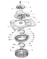
次に、図5〜図11を参照して、スイッチ操作装置を更に詳しく説明する。図5はスイッチ操作装置の分解斜視図、図6は図5の下方から見たスイッチ操作装置の分解斜視図である。 Next, the switch operation device will be described in more detail with reference to FIGS. FIG. 5 is an exploded perspective view of the switch operating device, and FIG. 6 is an exploded perspective view of the switch operating device viewed from below in FIG.
図5に示すように、操作部材2は、リング部2f、及びリング部2fの円周方向の一部に一体に設けられる操作レバー2cを有する。クリックばね9は、操作レバー2cを回動操作する際にクリック力を発生させるためのもので、円弧状に形成され、周方向の両端部に、径方向外側に突出する凸部9a,9bが径方向に互いに対向して設けられている。凸部9a,9bは、外装カバー1に形成されたクリックリブ1b,1cに嵌合保持される。
As shown in FIG. 5, the
クリックばね10は、操作ダイアル3を回転操作する際にクリック力を発生させるためのもので、クリックばね9と同様に、円弧状に形成されて、周方向の両端部に、径方向外側に突出する凸部10a,10bが径方向に互いに対向して設けられている。凸部10a,10bは、外装カバー1に形成されたクリックリブ1b,1cに嵌合保持される。
The
図6に示すように、リング部2fの内周部には、クリック溝2c−1,2d−1,2e−1、及びクリック溝2c−2,2d−2,2e−2(図7参照)が形成されている。クリック溝2c−1,2d−1,2e−1とクリック溝2c−2,2d−2,2e−2とは、互いに径方向に対向して配置されている。クリック溝2c−1,2c−2、クリック溝2d−1,2d−2、及びクリック溝2e−1,2e−2のいずれかがクリックばね9の凸部9a,9bに係合する。かかる係合状態においては、リング部2fは、クリックばね9によって径方向外方に付勢され、この状態で操作レバー2cを回動操作することで、クリック力を得ることができる。
As shown in FIG. 6, click
操作ダイアル3の内周部には、複数のクリック溝3aが周方向全周に形成されている。複数のクリック溝3aのうち径方向に互いに対向するクリック溝3a,3aがクリックばね10の凸部10a,10bに係合する。かかる係合状態においては、操作ダイアル3は、クリックばね10によって径方向外方に付勢され、この状態で操作ダイアル3を回転操作することで、クリック力を得ることができる。
A plurality of
フレキシブルプリント基板8のレバースイッチ7の実装部分には、図5に示すように、切欠き8aが形成され、切欠き8aには、レバースイッチ7の位置決めボス7b,7cが露出している。外装カバー1の位置決めボス7b,7cに対応する部位には、図6に示すように、外装凸部1dが形成され、外装凸部1dには、位置決めボス7b,7cが嵌合される。これにより、外装カバー1に対してレバースイッチ7が位置決めされる。フレキシブルプリント基板8は、不図示の両面テープ等を介して外装カバー1に接着固定される。また、外装カバー1には、操作ダイアル3の回転軸3bが貫通するダイアル穴部1eが形成されている。
As shown in FIG. 5, a
次に、図7〜図11を参照して、操作部材2及びクリックばね9を外装カバー1に組み付ける方法について説明する。図7は操作部材2のリング部2fの内周部にクリックばね9が保持された状態を背面側から見た図、図8はクリックばね9を保持した操作部材2を外装カバー1に組み付ける様子を示す斜視図である。なお、図8は、操作部材2のリング部2fの一部を破断して図示している。
Next, a method of assembling the
図7の状態では、クリックばね9の凸部9a,9bは、リング部2fのクリック溝2c−1,2c−2に係合しており、クリックばね9は、径方向外方に付勢された状態でリング部2fに保持されている。なお、図7の二点鎖線で示すように、リング部2fのクリック溝2d−1,2d−2又はクリック溝2e−1,2e−2に凸部9a,9bを係合させた状態であっても外装カバー1に組み込むことが可能である。
In the state of FIG. 7, the
図8に示すように、操作部材2に保持されたクリックばね9を外装カバー1に組み込んでいくと、凸部9a,9bが外装カバー1のクリックリブ1b,1cに嵌め込まれて保持され、また、操作片2a,2bが外装カバー1の穴部1aに挿入される。このとき、操作部材2は、外装カバー1に対して操作レバー2cの回動操作方向の位相が固定された状態、すなわち、操作レバー2cがOFF表示11aの位置の状態で外装カバー1に組み込まれる。
As shown in FIG. 8, when the
なお、リング部2fのクリック溝2d−1,2d−2に凸部9a,9bを係合させた場合は、操作レバー2cがON表示11cの位置で操作部材2が外装カバー1に組み込まれる。また、リング部2fのクリック溝2e−1,2e−2に凸部9a,9bを係合させた場合は、操作レバー2cが□表示11bの位置で操作部材2が外装カバー1に組み込まれる。
When the
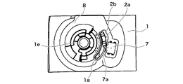
図9は、操作レバー2cがOFF表示11aの位置(図8)で操作部材2を外装カバー1に組み込んだ状態を背面側から見た図である。図10は操作レバー2cがON表示11cの位置で操作部材2を外装カバー1に組み込んだ状態を背面側から見た図、図11は操作レバー2cが□表示11bの位置で操作部材2を外装カバー1に組み込んだ状態を背面側から見た図である。
FIG. 9 is a view of the state in which the
図9〜図11のいずれの場合も、操作レバー2cの操作片2a,2bは、レバースイッチ7のレバー部7aに対して干渉しない位置に配置されている。すなわち、図9の状態では、操作レバー2cの操作片2aがレバー部7aに対して操作レバー2cの回動操作方向の矢印a方向に離れた位置に配置される。言い換えると、凸部9a,9bが外装カバー1のクリックリブ1b,1cに係合することで、レバー部7aの位置が操作レバー2cの操作片2aの外側となる位置となるように、操作部材2の組み付け位置を案内する。また、図10の状態では、操作レバー2cの操作片2a,2bがレバー部7aを挟む位置に配置される。言い換えると、凸部9a,9bが外装カバー1のクリックリブ1b,1cに係合することで、レバー部7aの位置が操作レバー2cの操作片2a,2bの間となる位置となるように、操作部材2の組み付け位置を案内する。図11の状態では、操作レバー2cの操作片2bがレバー部7aに対して操作レバー2cの回動操作方向の矢印b方向に離れた位置に配置される。言い換えると、凸部9a,9bが外装カバー1のクリックリブ1b,1cに係合することで、レバー部7aの位置が操作レバー2cの操作片2bの外側となる位置となるように、操作部材2の組み付け位置を案内する。したがって、操作部材2をどのように組み付けても、レバー部7aの位置が2つの操作片の間となる位置となるか、一方の操作片の外側となる位置のいずれかとなる。
9 to 11, the
なお、図9の場合は、組み付け後、操作レバー2cを矢印b方向に回動操作して操作片2aでレバー部7cを作動方向に押すことで、操作レバー2cの操作片2a,2bがレバー部7aを挟む位置に配置される。また、図11の場合は、組み付け後、操作レバー2cを矢印a方向に回動操作して操作片2bでレバー部7cを作動方向に押すことで、操作レバー2cの操作片2a,2bがレバー部7aを挟む位置に配置される。
In the case of FIG. 9, after assembling, the operating
以上説明したように、本実施形態では、操作部材2を外装カバー1に組み付ける際に、レバースイッチ7のレバー部7aに操作片2a,2bが干渉することがないため、レバースイッチ7の破損を防止することができる。また、操作部材2は、外装カバー1に対して操作レバー2cの回動操作方向の位相が固定された状態で外装カバー1に組み込まれるため、前記位相を固定するための冶具等を別途用意する必要もない。
As described above, in this embodiment, when the
また、本実施形態では、操作レバー2cの操作片2a,2bでレバースイッチ7のレバー部7aを作動方向と異なる方向に押し付けることがないので、従来のように、操作片2a,2bを弾性部材などで形成する必要がない。このため、部品点数が削減されて、スイッチ操作装置の組立作業性が向上するとともに、低コスト化を図ることができる。
In the present embodiment, the
更に、本実施形態では、レバースイッチ7のレバー部7aは、作動方向と異なる方向の押し付け荷重に対して十分な強度を持たなくてよいため、使用するレバースイッチ7の種類を限定しなくてすむ。
Furthermore, in the present embodiment, the
なお、本発明の構成は、上記実施形態に例示したものに限定されるものではなく、材質、形状、寸法、形態、数、配置箇所等は、本発明の要旨を逸脱しない範囲において適宜変更可能である。 The configuration of the present invention is not limited to that exemplified in the above embodiment, and the material, shape, dimensions, form, number, arrangement location, and the like can be changed as appropriate without departing from the scope of the present invention. It is.
1 外装カバー
1b,1c クリックリブ
2 操作部材
2a,2b 操作片
7 レバースイッチ
7a レバー部
9 クリックばね
9a,9b 凸部
DESCRIPTION OF
Claims (3)
前記固定部材に固定され、レバー部が作動することで検知信号を出力するレバースイッチと、
前記固定部材に回動操作可能に組み付けられ、クリック溝を有するとともに、前記回動操作により前記レバー部を作動方向に押し付けて作動させる操作片を有する操作部材と、
前記操作部材の前記クリック溝に保持された状態で、前記操作部材とともに前記固定部材に組み付けられ、前記組み付け状態で前記固定部材に固定されるクリックばねと、を備え、
前記操作片は、前記操作部材の回動操作方向に互いに離間して2つ設けられ、
前記クリック溝に前記クリックばねが保持された状態で前記操作部材を前記固定部材に組み付ける際には、前記クリックばねと前記固定部材とが係合することで、前記操作片の位置が前記レバースイッチの前記レバー部の位置に対して前記回動操作方向に離れた位置で、前記レバー部の位置が2つの前記操作片の間となる位置か、一方の前記操作片の外側となる位置のいずれかとなるように、前記操作部材の組み付け位置を案内することを特徴とするスイッチ操作装置。 A fixing member;
A lever switch that is fixed to the fixing member and outputs a detection signal by operating the lever portion;
An operation member that is assembled to the fixing member so as to be capable of rotating operation, has a click groove, and has an operation piece that is operated by pressing the lever portion in an operation direction by the rotation operation,
A click spring that is assembled to the fixing member together with the operation member in a state of being held in the click groove of the operation member, and is fixed to the fixing member in the assembled state;
Two operation pieces are provided apart from each other in the rotation operation direction of the operation member,
When the operation member is assembled to the fixed member with the click spring held in the click groove, the click spring and the fixed member are engaged with each other so that the position of the operation piece is the lever switch. The position of the lever portion is located between the two operation pieces at a position away from the position of the lever portion in the rotation operation direction, or a position that is outside the one operation piece. and so that if the switch operating device, characterized in that for guiding the mounting position of the operation member.
前記スイッチ操作装置として、請求項2に記載のスイッチ操作装置を備えることを特徴とする電子機器。 An electronic device comprising a switch operating device,
An electronic apparatus comprising the switch operation device according to claim 2 as the switch operation device.
Priority Applications (1)
| Application Number | Priority Date | Filing Date | Title |
|---|---|---|---|
| JP2012040021A JP5975673B2 (en) | 2012-02-27 | 2012-02-27 | Switch operating device and electronic device |
Applications Claiming Priority (1)
| Application Number | Priority Date | Filing Date | Title |
|---|---|---|---|
| JP2012040021A JP5975673B2 (en) | 2012-02-27 | 2012-02-27 | Switch operating device and electronic device |
Publications (2)
| Publication Number | Publication Date |
|---|---|
| JP2013175399A JP2013175399A (en) | 2013-09-05 |
| JP5975673B2 true JP5975673B2 (en) | 2016-08-23 |
Family
ID=49268131
Family Applications (1)
| Application Number | Title | Priority Date | Filing Date |
|---|---|---|---|
| JP2012040021A Expired - Fee Related JP5975673B2 (en) | 2012-02-27 | 2012-02-27 | Switch operating device and electronic device |
Country Status (1)
| Country | Link |
|---|---|
| JP (1) | JP5975673B2 (en) |
Families Citing this family (2)
| Publication number | Priority date | Publication date | Assignee | Title |
|---|---|---|---|---|
| JP6484495B2 (en) * | 2015-04-16 | 2019-03-13 | 日本発條株式会社 | Power seat operating device and power seat |
| JP7191702B2 (en) * | 2019-01-09 | 2022-12-19 | キヤノン株式会社 | Rotation input device and electronic device |
Family Cites Families (2)
| Publication number | Priority date | Publication date | Assignee | Title |
|---|---|---|---|---|
| JP2002324457A (en) * | 2001-04-26 | 2002-11-08 | Zexel Valeo Climate Control Corp | Automatic home return shuttle switch mechanism |
| JP5359928B2 (en) * | 2010-02-24 | 2013-12-04 | 住友電装株式会社 | Rotary operation device |
-
2012
- 2012-02-27 JP JP2012040021A patent/JP5975673B2/en not_active Expired - Fee Related
Also Published As
| Publication number | Publication date |
|---|---|
| JP2013175399A (en) | 2013-09-05 |
Similar Documents
| Publication | Publication Date | Title |
|---|---|---|
| US8203087B2 (en) | Key assembly used in an electronic device | |
| US8440928B2 (en) | Rotary electronic component | |
| JP2011175938A (en) | Operation input device and electronic apparatus using the same | |
| JP4311495B1 (en) | Operation input device and electronic apparatus using the same | |
| KR20070122364A (en) | Complex operation type input device | |
| JP4301312B2 (en) | Operation input device and electronic apparatus using the same | |
| KR20130027255A (en) | Key assembly and rotary input device using the same | |
| JP4472730B2 (en) | Input device | |
| JP4306669B2 (en) | Operation input device and electronic apparatus using the same | |
| JP4830862B2 (en) | Operation input device and electronic apparatus using the same | |
| JP4061626B2 (en) | Rotation input device | |
| JP5975673B2 (en) | Switch operating device and electronic device | |
| JP4737197B2 (en) | Operation input device and electronic apparatus using the same | |
| JP5338592B2 (en) | Operation input device and electronic apparatus using the same | |
| JP2011164117A (en) | Electronic equipment | |
| JP6662687B2 (en) | Rotary electronic components | |
| JP2013097970A (en) | Electronic apparatus | |
| JP2008071590A (en) | Rotating electronic components | |
| JP4471905B2 (en) | Switch structure and portable communication device having the same | |
| JP6166165B2 (en) | Combined operation type input device | |
| JP5483648B1 (en) | Input device | |
| JP6448285B2 (en) | Electronics | |
| JP4578545B2 (en) | Input device | |
| JP7146456B2 (en) | Rotating/swinging input device and electronic equipment | |
| JP2008071589A (en) | Multi-directional push switch |
Legal Events
| Date | Code | Title | Description |
|---|---|---|---|
| A621 | Written request for application examination |
Free format text: JAPANESE INTERMEDIATE CODE: A621 Effective date: 20150128 |
|
| A977 | Report on retrieval |
Free format text: JAPANESE INTERMEDIATE CODE: A971007 Effective date: 20151130 |
|
| A131 | Notification of reasons for refusal |
Free format text: JAPANESE INTERMEDIATE CODE: A131 Effective date: 20151201 |
|
| A521 | Request for written amendment filed |
Free format text: JAPANESE INTERMEDIATE CODE: A523 Effective date: 20160127 |
|
| TRDD | Decision of grant or rejection written | ||
| A01 | Written decision to grant a patent or to grant a registration (utility model) |
Free format text: JAPANESE INTERMEDIATE CODE: A01 Effective date: 20160621 |
|
| A61 | First payment of annual fees (during grant procedure) |
Free format text: JAPANESE INTERMEDIATE CODE: A61 Effective date: 20160719 |
|
| R151 | Written notification of patent or utility model registration |
Ref document number: 5975673 Country of ref document: JP Free format text: JAPANESE INTERMEDIATE CODE: R151 |
|
| LAPS | Cancellation because of no payment of annual fees |