JP5974209B1 - Position detection system - Google Patents
Position detection system Download PDFInfo
- Publication number
- JP5974209B1 JP5974209B1 JP2016525113A JP2016525113A JP5974209B1 JP 5974209 B1 JP5974209 B1 JP 5974209B1 JP 2016525113 A JP2016525113 A JP 2016525113A JP 2016525113 A JP2016525113 A JP 2016525113A JP 5974209 B1 JP5974209 B1 JP 5974209B1
- Authority
- JP
- Japan
- Prior art keywords
- magnetic field
- detection
- coil
- unit
- value
- Prior art date
- Legal status (The legal status is an assumption and is not a legal conclusion. Google has not performed a legal analysis and makes no representation as to the accuracy of the status listed.)
- Expired - Fee Related
Links
Images


Classifications
-
- G—PHYSICS
- G01—MEASURING; TESTING
- G01D—MEASURING NOT SPECIALLY ADAPTED FOR A SPECIFIC VARIABLE; ARRANGEMENTS FOR MEASURING TWO OR MORE VARIABLES NOT COVERED IN A SINGLE OTHER SUBCLASS; TARIFF METERING APPARATUS; MEASURING OR TESTING NOT OTHERWISE PROVIDED FOR
- G01D5/00—Mechanical means for transferring the output of a sensing member; Means for converting the output of a sensing member to another variable where the form or nature of the sensing member does not constrain the means for converting; Transducers not specially adapted for a specific variable
- G01D5/12—Mechanical means for transferring the output of a sensing member; Means for converting the output of a sensing member to another variable where the form or nature of the sensing member does not constrain the means for converting; Transducers not specially adapted for a specific variable using electric or magnetic means
- G01D5/14—Mechanical means for transferring the output of a sensing member; Means for converting the output of a sensing member to another variable where the form or nature of the sensing member does not constrain the means for converting; Transducers not specially adapted for a specific variable using electric or magnetic means influencing the magnitude of a current or voltage
- G01D5/20—Mechanical means for transferring the output of a sensing member; Means for converting the output of a sensing member to another variable where the form or nature of the sensing member does not constrain the means for converting; Transducers not specially adapted for a specific variable using electric or magnetic means influencing the magnitude of a current or voltage by varying inductance, e.g. by a movable armature
-
- A—HUMAN NECESSITIES
- A61—MEDICAL OR VETERINARY SCIENCE; HYGIENE
- A61B—DIAGNOSIS; SURGERY; IDENTIFICATION
- A61B1/00—Instruments for performing medical examinations of the interior of cavities or tubes of the body by visual or photographical inspection, e.g. endoscopes; Illuminating arrangements therefor
- A61B1/00147—Holding or positioning arrangements
- A61B1/00158—Holding or positioning arrangements using magnetic field
-
- A—HUMAN NECESSITIES
- A61—MEDICAL OR VETERINARY SCIENCE; HYGIENE
- A61B—DIAGNOSIS; SURGERY; IDENTIFICATION
- A61B1/00—Instruments for performing medical examinations of the interior of cavities or tubes of the body by visual or photographical inspection, e.g. endoscopes; Illuminating arrangements therefor
- A61B1/04—Instruments for performing medical examinations of the interior of cavities or tubes of the body by visual or photographical inspection, e.g. endoscopes; Illuminating arrangements therefor combined with photographic or television appliances
- A61B1/041—Capsule endoscopes for imaging
-
- A—HUMAN NECESSITIES
- A61—MEDICAL OR VETERINARY SCIENCE; HYGIENE
- A61B—DIAGNOSIS; SURGERY; IDENTIFICATION
- A61B5/00—Measuring for diagnostic purposes; Identification of persons
- A61B5/06—Devices, other than using radiation, for detecting or locating foreign bodies ; determining position of probes within or on the body of the patient
- A61B5/061—Determining position of a probe within the body employing means separate from the probe, e.g. sensing internal probe position employing impedance electrodes on the surface of the body
- A61B5/062—Determining position of a probe within the body employing means separate from the probe, e.g. sensing internal probe position employing impedance electrodes on the surface of the body using magnetic field
-
- A—HUMAN NECESSITIES
- A61—MEDICAL OR VETERINARY SCIENCE; HYGIENE
- A61B—DIAGNOSIS; SURGERY; IDENTIFICATION
- A61B5/00—Measuring for diagnostic purposes; Identification of persons
- A61B5/07—Endoradiosondes
- A61B5/073—Intestinal transmitters
-
- G—PHYSICS
- G01—MEASURING; TESTING
- G01D—MEASURING NOT SPECIALLY ADAPTED FOR A SPECIFIC VARIABLE; ARRANGEMENTS FOR MEASURING TWO OR MORE VARIABLES NOT COVERED IN A SINGLE OTHER SUBCLASS; TARIFF METERING APPARATUS; MEASURING OR TESTING NOT OTHERWISE PROVIDED FOR
- G01D5/00—Mechanical means for transferring the output of a sensing member; Means for converting the output of a sensing member to another variable where the form or nature of the sensing member does not constrain the means for converting; Transducers not specially adapted for a specific variable
- G01D5/12—Mechanical means for transferring the output of a sensing member; Means for converting the output of a sensing member to another variable where the form or nature of the sensing member does not constrain the means for converting; Transducers not specially adapted for a specific variable using electric or magnetic means
- G01D5/14—Mechanical means for transferring the output of a sensing member; Means for converting the output of a sensing member to another variable where the form or nature of the sensing member does not constrain the means for converting; Transducers not specially adapted for a specific variable using electric or magnetic means influencing the magnitude of a current or voltage
- G01D5/20—Mechanical means for transferring the output of a sensing member; Means for converting the output of a sensing member to another variable where the form or nature of the sensing member does not constrain the means for converting; Transducers not specially adapted for a specific variable using electric or magnetic means influencing the magnitude of a current or voltage by varying inductance, e.g. by a movable armature
- G01D5/204—Mechanical means for transferring the output of a sensing member; Means for converting the output of a sensing member to another variable where the form or nature of the sensing member does not constrain the means for converting; Transducers not specially adapted for a specific variable using electric or magnetic means influencing the magnitude of a current or voltage by varying inductance, e.g. by a movable armature by influencing the mutual induction between two or more coils
- G01D5/2066—Mechanical means for transferring the output of a sensing member; Means for converting the output of a sensing member to another variable where the form or nature of the sensing member does not constrain the means for converting; Transducers not specially adapted for a specific variable using electric or magnetic means influencing the magnitude of a current or voltage by varying inductance, e.g. by a movable armature by influencing the mutual induction between two or more coils by movement of a single coil with respect to a single other coil
-
- A—HUMAN NECESSITIES
- A61—MEDICAL OR VETERINARY SCIENCE; HYGIENE
- A61B—DIAGNOSIS; SURGERY; IDENTIFICATION
- A61B5/00—Measuring for diagnostic purposes; Identification of persons
- A61B5/72—Signal processing specially adapted for physiological signals or for diagnostic purposes
- A61B5/7235—Details of waveform analysis
- A61B5/7253—Details of waveform analysis characterised by using transforms
- A61B5/7257—Details of waveform analysis characterised by using transforms using Fourier transforms
Abstract
位置検出システムは、共振回路の一部をなし、電流が流れることにより磁界を発生するマーカコイルが内部に設けられたカプセル型内視鏡と、マーカコイルが発生する磁界を検出して検出信号を出力する複数のセンスコイルと、マーカコイルが発生する磁界に対するSN比が複数のセンスコイルにより検出された検出信号におけるSN比よりも小さい位置に配置された参照コイルと、参照コイルから出力された検出信号に基づく磁界検出値を用いて、複数のセンスコイルからそれぞれ出力された複数の検出信号に基づく磁界検出値を補正し、補正された磁界検出値を用いてカプセル型内視鏡の位置を算出する演算部とを備える。The position detection system is a part of a resonance circuit, and a capsule endoscope in which a marker coil that generates a magnetic field when current flows and a magnetic field generated by the marker coil are detected and a detection signal is output. A plurality of sense coils to be output, a reference coil disposed at a position where the SN ratio with respect to the magnetic field generated by the marker coil is smaller than the SN ratio in the detection signal detected by the plurality of sense coils, and the detection output from the reference coil Using the magnetic field detection value based on the signal, the magnetic field detection value based on the plurality of detection signals output from each of the plurality of sense coils is corrected, and the position of the capsule endoscope is calculated using the corrected magnetic field detection value. And a calculation unit.
Description
本発明は、被検体内に導入されたカプセル型医療装置の位置を検出する位置検出システムに関する。 The present invention relates to a position detection system that detects the position of a capsule medical device introduced into a subject.
従来、被検体内に導入されて被検体内に関する種々の情報を取得する、或いは、被検体内に薬剤等を投与するといった用途でカプセル型医療装置が開発されている。一例として、内視鏡の分野においては、被検体の消化管内(管腔内)に導入可能な大きさに形成されたカプセル型内視鏡が知られている。カプセル型内視鏡は、カプセル形状をなす筐体の内部に撮像機能及び無線通信機能を備えたものであり、被検体に嚥下された後、蠕動運動等によって消化管内を移動しながら撮像を行い、被検体の臓器内部の画像(以下、体内画像ともいう)の画像データを順次、無線送信する。無線送信された画像データは、被検体外に設けられた受信装置によって受信され、さらに、ワークステーション等の画像処理装置に取り込まれて所定の画像処理が施される。それにより、画像処理装置において、被検体の体内画像を静止画又は動画により再生表示することができる。 2. Description of the Related Art Conventionally, capsule medical devices have been developed for use such as being introduced into a subject to acquire various information about the subject, or administering a drug or the like into the subject. As an example, in the field of endoscopes, capsule endoscopes that have a size that can be introduced into the digestive tract (intraluminal) of a subject are known. A capsule endoscope has an imaging function and a wireless communication function inside a capsule-shaped casing, and after swallowing by a subject, performs imaging while moving in the digestive tract by peristalsis or the like. Then, image data of an image inside the organ of the subject (hereinafter also referred to as an in-vivo image) is sequentially wirelessly transmitted. The wirelessly transmitted image data is received by a receiving device provided outside the subject, and further taken into an image processing device such as a workstation and subjected to predetermined image processing. Accordingly, the in-vivo image of the subject can be reproduced and displayed as a still image or a moving image in the image processing apparatus.
併せて、被検体内におけるカプセル型医療装置の位置を検出するシステムも開発されている。例えば特許文献1には、磁界を発生するコイル(以下、マーカコイル)をカプセル型内視鏡内に設け、被検体外に設けられた磁界検出用のコイル(以下、センスコイル)によってマーカコイルが発生した磁界(以下、マーカ磁界)を検出し、検出した磁界の強度に基づいてカプセル型内視鏡の位置を推定する位置検出システムが開示されている。このカプセル型内視鏡においては、カプセル型内視鏡が検出対象空間内に位置しない状態(マーカコイルがオフの状態)で予め取得したセンスコイルの検出値を用いて、カプセル型内視鏡の位置検出中における検出値を補正することにより、位置検出システムの周辺環境の影響を除外している。
In addition, a system for detecting the position of the capsule medical device in the subject has been developed. For example, in
ところで、位置検出システムにおいては、カプセル型医療装置の省電力化のため、マーカコイルに供給する電力を低減することが好ましい。ところが、供給電力の低減によりマーカ磁界の強度が弱くなるので、マーカ磁界の検出信号のSN比を向上させるために、センスコイルを含む磁界検出部における低ノイズ化が図られている。具体的には、金属とコイルとの磁界干渉といった位置検出システム内におけるノイズ源に対する対策が講じられている。 By the way, in the position detection system, it is preferable to reduce the power supplied to the marker coil in order to save power of the capsule medical device. However, since the strength of the marker magnetic field is weakened due to the reduction in power supply, in order to improve the S / N ratio of the detection signal of the marker magnetic field, the noise in the magnetic field detection unit including the sense coil is reduced. Specifically, measures are taken against noise sources in the position detection system such as magnetic field interference between a metal and a coil.
しかしながら、磁界検出部の低ノイズ化に伴い、位置検出システムの周辺から発生源が不明な磁界(以下、環境磁界)が検出される。その結果、環境磁界自体がノイズとなり、位置検出用磁界の検出信号のSN比が低下して、カプセル型医療装置の位置精度が低下するという問題が生じていた。 However, as the noise of the magnetic field detector is reduced, a magnetic field whose source is unknown (hereinafter referred to as an environmental magnetic field) is detected from the periphery of the position detection system. As a result, the environmental magnetic field itself becomes noise, and the S / N ratio of the detection signal of the position detection magnetic field is lowered, resulting in a problem that the position accuracy of the capsule medical device is lowered.
環境磁界は短時間に変化するため、上記特許文献1に記載の位置検出システムでは、磁界発生コイルをオフからオンに切り替える間に変動した高周波の環境磁界によるノイズを補正することが困難である。また、このような環境磁界は発生源を特定できないため、補正値を取得することが非常に困難である。
Since the environmental magnetic field changes in a short time, it is difficult for the position detection system described in
本発明は、上記に鑑みてなされたものであって、短時間に変化する環境磁界の影響を除外し、カプセル型医療装置の位置を精度良く検出することができる位置検出システムを提供することを目的とする。 The present invention has been made in view of the above, and provides a position detection system that can accurately detect the position of a capsule medical device by eliminating the influence of an environmental magnetic field that changes in a short time. Objective.
上述した課題を解決し、目的を達成するために、本発明に係る位置検出システムは、共振回路の一部をなし、電流が流れることにより磁界を発生する第1のコイルが内部に設けられたカプセル型医療装置と、各々が前記第1のコイルが発生する磁界を検出して検出信号を出力する複数の第2のコイルと、磁界を検出して検出信号を出力する少なくとも1つの第3のコイルであって、前記第1のコイルが発生する磁界に対するSN比が、前記複数の第2のコイルの各々により検出された検出信号におけるSN比よりも小さい位置に配置された少なくとも1つの第3のコイルと、前記少なくとも1つの第3のコイルから出力された検出信号に基づく磁界の検出値である参照磁界検出値を用いて、前記複数の第2のコイルからそれぞれ出力された複数の検出信号に基づく複数の磁界検出値を補正することにより、複数の補正済み磁界検出値を算出し、該複数の補正済み磁界検出値に基づいて前記カプセル型医療装置の位置を算出する演算部と、を備えることを特徴とする。 In order to solve the above-described problems and achieve the object, a position detection system according to the present invention includes a first coil that forms a part of a resonance circuit and generates a magnetic field when a current flows. A capsule-type medical device; a plurality of second coils each detecting a magnetic field generated by the first coil and outputting a detection signal; and at least one third coil detecting a magnetic field and outputting a detection signal And at least one third coil disposed at a position where an SN ratio to a magnetic field generated by the first coil is smaller than an SN ratio in a detection signal detected by each of the plurality of second coils. And a reference magnetic field detection value that is a detection value of a magnetic field based on a detection signal output from the at least one third coil, and a plurality of outputs output from the plurality of second coils. A calculation unit that calculates a plurality of corrected magnetic field detection values by correcting a plurality of magnetic field detection values based on the detection signals of the plurality of magnetic field detection values, and calculates a position of the capsule medical device based on the plurality of corrected magnetic field detection values And.
上記位置検出システムにおいて、前記演算部は、前記複数の第2のコイルの各々に対し、同じタイミングで前記少なくとも1つの第3のコイルから出力された検出信号に基づいて演算を行うことを特徴とする。 In the above-described position detection system, the calculation unit performs a calculation on each of the plurality of second coils based on a detection signal output from the at least one third coil at the same timing. To do.
上記位置検出システムにおいて、前記少なくとも1つの第3のコイルは、前記複数の第2のコイルよりも、前記カプセル型医療装置の検出対象領域から離れた位置に配置されていることを特徴とする。 In the position detection system, the at least one third coil is disposed at a position farther from the detection target region of the capsule medical device than the plurality of second coils.
上記位置検出システムにおいて、前記複数の第2のコイルは第1の平面上に配置され、前記少なくとも1つの第3のコイルは前記第1の平面と平行な第2の平面上に配置され、前記第1の平面と前記第2の平面との間隔は、前記検出対象領域と前記第1の平面との間隔よりも大きいことを特徴とする。 In the position detection system, the plurality of second coils are arranged on a first plane, the at least one third coil is arranged on a second plane parallel to the first plane, and An interval between the first plane and the second plane is larger than an interval between the detection target region and the first plane.
上記位置検出システムにおいて、前記第2の平面は、前記第1の平面に対して前記検出対象領域の反対側に配置されていることを特徴とする。 In the position detection system, the second plane is disposed on the opposite side of the detection target area with respect to the first plane.
上記位置検出システムは、前記第1の平面と前記第2の平面との間に配置された磁気シールド手段をさらに備えることを特徴とする。 The position detection system further includes magnetic shield means disposed between the first plane and the second plane.
上記位置検出システムにおいて、前記複数の第2のコイルは平面上に配置され、前記少なくとも1つの第3のコイルは、前記平面上で前記複数の第2のコイルが配置される領域よりも外側の領域に配置されていることを特徴とする。 In the above position detection system, the plurality of second coils are arranged on a plane, and the at least one third coil is outside a region on the plane where the plurality of second coils are arranged. It is characterized by being arranged in a region.
上記位置検出システムは、前記複数の第2のコイル及び前記少なくとも1つの第3のコイルの各々から出力された検出信号に基づく磁界検出値を記憶する記憶部をさらに備え、前記演算部は、前記第1のコイルが通電されていない状態において、前記複数の第2のコイルの少なくともいずれかから出力された第1の検出信号に基づく磁界検出値と、前記第1の検出信号と同一のタイミングで前記少なくとも1つの第3のコイルから出力された第2の検出信号に基づく参照磁界検出値との比を算出して前記記憶部に記憶させ、前記第1のコイルが通電された状態において、前記少なくとも1つの第3のコイルから出力された第3の検出信号に基づく参照磁界検出値と前記比とに基づいて補正値を算出し、該補正値を用いて、前記第3の検出信号と同一のタイミングで前記複数の第2のコイルからそれぞれ出力された複数の検出信号に基づく複数の磁界検出値を補正することを特徴とする。 The position detection system further includes a storage unit that stores a magnetic field detection value based on a detection signal output from each of the plurality of second coils and the at least one third coil, and the calculation unit includes: In a state where the first coil is not energized, the magnetic field detection value based on the first detection signal output from at least one of the plurality of second coils and the same timing as the first detection signal A ratio with a reference magnetic field detection value based on a second detection signal output from the at least one third coil is calculated and stored in the storage unit, and in a state where the first coil is energized, A correction value is calculated based on a reference magnetic field detection value based on a third detection signal output from at least one third coil and the ratio, and the third detection signal is calculated using the correction value. And correcting a plurality of magnetic field detection value based on the plurality of detection signals respectively outputted at the same timing from the plurality of second coils.
上記位置検出システムにおいて、前記演算部は、前記カプセル型医療装置の電源がオンされた際に、前記比を算出することを特徴とする。 In the position detection system, the arithmetic unit calculates the ratio when the capsule medical device is powered on.
上記位置検出システムは、当該位置検出システムに対してキャリブレーションの指示を入力するために用いられる操作スイッチをさらに備え、前記演算部は、前記操作スイッチに対する操作が行われた際に、前記比を算出することを特徴とする。 The position detection system further includes an operation switch used to input a calibration instruction to the position detection system, and the calculation unit calculates the ratio when an operation is performed on the operation switch. It is characterized by calculating.
上記位置検出システムにおいて、前記第1のコイルは間欠的に通電され、前記演算部は、前記第1のコイルが通電されていない各タイミングにおいて出力された前記第1及び第2の検出信号に基づいて前記比を算出することを特徴とする。 In the position detection system, the first coil is intermittently energized, and the calculation unit is based on the first and second detection signals output at each timing when the first coil is not energized. And calculating the ratio.
上記位置検出システムにおいて、前記複数の第2のコイルは、各々の中心軸が互いに異なる方向を向いた3つの第2のコイルを含み、前記少なくとも1つの第3のコイルは、各々の中心軸が互いに異なる方向を向いた3つの第3のコイルを含み、前記演算部は、互いに平行な中心軸をそれぞれ有する前記第2のコイルと前記第3のコイルとの間で、前記比を算出することを特徴とする。 In the position detection system, the plurality of second coils include three second coils whose central axes are directed in different directions, and the at least one third coil includes The calculation unit includes three third coils facing in different directions, and the calculation unit calculates the ratio between the second coil and the third coil, each having a central axis parallel to each other. It is characterized by.
上記位置検出システムは、前記第3のコイルを複数備えると共に、前記演算部による前記カプセル型医療装置の位置算出結果に基づき、1つの前記第3のコイルを選択する制御部をさらに備え、前記演算部は、前記制御部により選択された第3のコイルから出力された検出信号に基づく参照磁界検出値を用いて、前記補正済み磁界検出値を算出することを特徴とする。 The position detection system includes a plurality of the third coils, and further includes a control unit that selects one third coil based on a position calculation result of the capsule medical device by the calculation unit, The unit calculates the corrected magnetic field detection value using a reference magnetic field detection value based on a detection signal output from the third coil selected by the control unit.
上記位置検出システムにおいて、前記制御部は、複数の前記第3のコイルのうち、前記位置算出結果に基づく前記カプセル型医療装置の位置から最も離れた第3のコイルを選択することを特徴とする。 In the position detection system, the control unit selects a third coil farthest from the position of the capsule medical device based on the position calculation result among the plurality of third coils. .
本発明に係る位置検出システムは、共振回路の一部をなし、電流が流れることにより磁界を発生する第1のコイルが内部に設けられたカプセル型医療装置と、各々が前記第1のコイルが発生する磁界を検出して検出信号を出力する複数の第2のコイルと、前記複数の第2のコイルのうちの少なくとも1つの第2のコイルを選択する制御部と、前記制御部により選択された前記少なくとも1つの第2のコイルから出力された検出信号に基づく磁界の検出値である参照磁界検出値を用いて、前記複数の第2のコイルのうち、前記制御部により選択された前記少なくとも1つの第2のコイル以外の第2のコイルからそれぞれ出力された複数の検出信号に基づく複数の磁界検出値を補正することにより、複数の補正済み磁界検出値を算出し、該複数の補正済み磁界検出値に基づいて前記カプセル型医療装置の位置を算出する演算部と、を備えることを特徴とする。 The position detection system according to the present invention includes a capsule medical device that includes a first coil that forms a part of a resonance circuit and generates a magnetic field when current flows, and each of the first coil includes A plurality of second coils that detect a generated magnetic field and output a detection signal; a control unit that selects at least one second coil of the plurality of second coils; and the control unit that is selected. The at least one selected from the plurality of second coils by the control unit using a reference magnetic field detection value that is a detection value of a magnetic field based on a detection signal output from the at least one second coil. A plurality of corrected magnetic field detection values are calculated by correcting a plurality of magnetic field detection values based on a plurality of detection signals respectively output from the second coils other than one second coil. A calculation unit based on the Tadashizumi magnetic field detection value to calculate the position of the capsule medical device, characterized in that it comprises a.
上記位置検出システムにおいて、前記制御部は、前記演算部による前記カプセル型医療装置の位置算出結果に基づき、前記第1のコイルが発生する磁界に対するSN比が最も小さい前記第2のコイルを選択することを特徴とする。 In the position detection system, the control unit selects the second coil having the smallest SN ratio with respect to the magnetic field generated by the first coil, based on the position calculation result of the capsule medical device by the calculation unit. It is characterized by that.
本発明に係る位置検出システムは、共振回路の一部をなし、電力供給を受けて位置検出用磁界を発生する磁界発生コイルを内部に有するカプセル型医療装置と、前記カプセル型医療装置から発生した前記位置検出用磁界を検出して複数の検出信号をそれぞれ出力する複数の磁界検出コイルと、前記位置検出用磁界の検出空間に存在する環境磁界を検出し、該環境磁界の検出信号を参照信号として出力する参照コイルと、前記参照信号を用いて前記複数の検出信号の出力値をそれぞれ補正した複数の補正値を算出する磁界補正部と、前記複数の補正値に基づいて、前記カプセル型医療装置の位置を算出する位置算出部と、を備え、前記磁界補正部は、前記複数の検出信号の各々に対し、各検出信号に含まれる第1の周波数帯域成分を抽出して、該第1の周波数帯域成分の第1の値を出力する第1フィルタ処理と、前記参照信号に含まれる前記第1の周波数帯域成分を抽出して、該第1の周波数帯域成分の第2の値を出力する第2フィルタ処理と、前記参照信号に含まれる前記第1の周波数帯域成分と異なる第2の周波数帯域成分を抽出して、該第2の周波数帯域成分の第3の値を出力する第3フィルタ処理と、前記第1の値と前記第2の値との比率を算出する比率算出処理と、前記比率と前記第3の値とを用いて、前記検出信号に含まれる環境磁界成分の値を算出する環境磁界算出処理と、当該検出信号の出力値から前記環境磁界成分の値を減算することにより、前記位置検出用磁界の磁界成分の値を算出する減算処理と、を施すことを特徴とする。 A position detection system according to the present invention includes a capsule medical device that forms part of a resonance circuit and has a magnetic field generating coil that receives a power supply to generate a magnetic field for position detection. The capsule medical device is generated from the capsule medical device. A plurality of magnetic field detection coils for detecting the position detection magnetic field and outputting a plurality of detection signals respectively, and detecting an environmental magnetic field existing in a detection space of the position detection magnetic field, and detecting the detection signal of the environmental magnetic field as a reference signal A reference coil that outputs the reference value; a magnetic field correction unit that calculates a plurality of correction values obtained by correcting the output values of the plurality of detection signals using the reference signal; and the capsule medical based on the plurality of correction values A position calculation unit that calculates the position of the device, and the magnetic field correction unit extracts, for each of the plurality of detection signals, a first frequency band component included in each detection signal, A first filtering process that outputs a first value of the first frequency band component; and a second value of the first frequency band component that is extracted from the first frequency band component included in the reference signal. And a second frequency band component different from the first frequency band component included in the reference signal is extracted, and a third value of the second frequency band component is output. An environmental magnetic field component included in the detection signal using a third filter process, a ratio calculation process for calculating a ratio between the first value and the second value, and the ratio and the third value An environmental magnetic field calculation process for calculating the value of the magnetic field component, and a subtraction process for calculating the value of the magnetic field component of the position detection magnetic field by subtracting the value of the environmental magnetic field component from the output value of the detection signal. It is characterized by.
上記位置検出システムにおいて、前記参照コイルが複数設けられ、複数の前記参照コイルがそれぞれ出力した複数の参照信号のうちから、前記磁界補正部において用いる参照信号を選択する参照信号選択部をさらに備え、前記磁界補正部は、前記参照信号選択部が選択した参照信号を用いて前記複数の補正値を算出する、ことを特徴とする。 In the position detection system, a plurality of reference coils are provided, and a reference signal selection unit that selects a reference signal to be used in the magnetic field correction unit from a plurality of reference signals output from the plurality of reference coils, respectively. The magnetic field correction unit calculates the plurality of correction values using a reference signal selected by the reference signal selection unit.
上記位置検出システムにおいて、前記参照信号選択部は、前記複数の参照信号のうち、出力値が最小の参照信号を選択する、ことを特徴とする。 In the position detection system, the reference signal selection unit selects a reference signal having a minimum output value from the plurality of reference signals.
本発明に係る位置検出システムは、共振回路の一部をなし、電力供給を受けて位置検出用磁界を発生する磁界発生コイルを内部に有するカプセル型医療装置と、前記カプセル型医療装置から発生した前記位置検出用磁界を検出して複数の検出信号をそれぞれ出力する複数の磁界検出コイルと、前記複数の磁界検出コイルのうちから、前記位置検出用磁界の検出空間に存在する環境磁界を検出させ、該環境磁界の検出信号を参照信号として出力させる磁界検出コイルを選択するコイル選択部と、前記コイル選択部が選択した磁界検出コイルから出力された前記参照信号を用いて、前記複数の検出信号の出力値をそれぞれ補正した複数の補正値を算出する磁界補正部と、前記複数の補正値に基づいて、前記カプセル型医療装置の位置を算出する位置算出部と、を備え、前記磁界補正部は、前記複数の検出信号の各々に対し、各検出信号に含まれる第1の周波数帯域成分を抽出して、該第1の周波数帯域成分の第1の値を出力する第1フィルタ処理と、前記参照信号に含まれる前記第1の周波数帯域成分を抽出して、該第1の周波数帯域成分の第2の値を出力する第2フィルタ処理と、前記参照信号に含まれる前記第1の周波数帯域成分と異なる第2の周波数帯域成分を抽出して、該第2の周波数帯域成分の第3の値を出力する第3フィルタ処理と、前記第1の値と前記第2の値との比率を算出する比率算出処理と、前記比率と前記第3の値とを用いて、前記検出信号に含まれる環境磁界成分の値を算出する環境磁界算出処理と、当該検出信号の出力値から前記環境磁界成分の値を減算することにより、前記位置検出用磁界の磁界成分の値を算出する減算処理と、を施す、ことを特徴とする。 A position detection system according to the present invention includes a capsule medical device that forms part of a resonance circuit and has a magnetic field generating coil that receives a power supply to generate a magnetic field for position detection. The capsule medical device is generated from the capsule medical device. A plurality of magnetic field detection coils that detect the position detection magnetic field and output a plurality of detection signals, respectively, and an environmental magnetic field existing in the position detection magnetic field detection space is detected from the plurality of magnetic field detection coils. A plurality of detection signals using a coil selection unit that selects a magnetic field detection coil that outputs the detection signal of the environmental magnetic field as a reference signal, and the reference signal output from the magnetic field detection coil selected by the coil selection unit. A magnetic field correction unit that calculates a plurality of correction values obtained by correcting the respective output values, and a position that calculates the position of the capsule medical device based on the plurality of correction values. A calculation unit, wherein the magnetic field correction unit extracts a first frequency band component included in each detection signal for each of the plurality of detection signals, and outputs a first of the first frequency band components. A first filtering process that outputs a value of the first frequency band component, and a second filtering process that extracts the first frequency band component included in the reference signal and outputs a second value of the first frequency band component; A third filtering process for extracting a second frequency band component different from the first frequency band component included in the reference signal and outputting a third value of the second frequency band component; The ratio calculation process for calculating the ratio between the value of the second value and the second value, and the environmental magnetic field calculation process for calculating the value of the environmental magnetic field component included in the detection signal using the ratio and the third value And subtracting the value of the environmental magnetic field component from the output value of the detection signal. It the performs, the subtraction process of calculating the value of the magnetic field component of the position-detection magnetic field, characterized in that.
上記位置検出システムにおいて、前記参照コイル選択部は、前記磁界補正部により直前に算出された前記磁界成分の値が最小である磁界検出コイルを選択する、ことを特徴とする。 In the position detection system, the reference coil selection unit selects a magnetic field detection coil having a minimum value of the magnetic field component calculated immediately before by the magnetic field correction unit.
上記位置検出システムにおいて、前記第1、第2、及び第3フィルタ処理は低域除去フィルタ処理であり、前記第3フィルタ処理におけるカットオフ周波数は、前記第1及び第2フィルタ処理におけるカットオフ周波数よりも小さい、ことを特徴とする。 In the position detection system, the first, second, and third filter processes are low-frequency elimination filter processes, and a cutoff frequency in the third filter process is a cutoff frequency in the first and second filter processes. Smaller than that.
上記位置検出システムにおいて、前記磁界補正部は、前記位置検出用磁界が有する最大周波数を前記第1及び第2フィルタ処理におけるカットオフ周波数として設定する、ことを特徴とする。 In the position detection system, the magnetic field correction unit sets a maximum frequency of the position detection magnetic field as a cutoff frequency in the first and second filter processes.
上記位置検出システムにおいて、前記磁界補正部は、前記位置算出部の算出結果に基づいて、前記第1及び第2フィルタ処理におけるカットオフ周波数を決定する、ことを特徴とする。 In the position detection system, the magnetic field correction unit determines a cutoff frequency in the first and second filter processes based on a calculation result of the position calculation unit.
上記位置検出システムにおいて、前記カプセル型医療装置は、永久磁石を有し、前記カプセル型医療装置の外部に設けられ、前記永久磁石に作用させることにより前記カプセル型医療装置を誘導する誘導用磁界を発生する誘導用磁界発生部と、前記誘導用磁界発生部の動作を制御する制御情報を出力する誘導用磁界制御部と、をさらに備え、前記磁界補正部は、前記制御情報に基づいて、前記第1及び第2フィルタ処理におけるカットオフ周波数を決定する、ことを特徴とする。 In the position detection system, the capsule medical device includes a permanent magnet, and is provided outside the capsule medical device, and generates a magnetic field for guiding the capsule medical device by acting on the permanent magnet. A guidance magnetic field generation unit that generates the guidance magnetic field control unit that outputs control information for controlling the operation of the guidance magnetic field generation unit, the magnetic field correction unit based on the control information, The cutoff frequency in the first and second filter processing is determined.
上記位置検出システムにおいて、前記磁界補正部は、前記複数の検出信号の出力値をそれぞれ補正する複数のチャネルを備え、前記複数の検出信号の出力値を並列で補正することを特徴とする。 In the position detection system, the magnetic field correction unit includes a plurality of channels that respectively correct output values of the plurality of detection signals, and corrects the output values of the plurality of detection signals in parallel.
上記位置検出システムにおいて、前記磁界補正部は、前記複数の検出信号の出力値を順次補正する、ことを特徴とする。 In the position detection system, the magnetic field correction unit sequentially corrects output values of the plurality of detection signals.
本発明によれば、短時間に変化する環境磁界の影響を除外し、カプセル型医療装置の位置を精度良く検出することができる。 According to the present invention, the influence of an environmental magnetic field that changes in a short time can be excluded, and the position of the capsule medical device can be detected with high accuracy.
以下に、本発明の実施の形態に係る位置検出システムについて、図面を参照しながら説明する。なお、以下の説明においては、本実施の形態に係る位置検出システムが検出対象とするカプセル型医療装置の一形態として、被検体内に経口にて導入されて被検体内(管腔内)を撮像するカプセル型内視鏡を例示するが、この実施の形態によって本発明が限定されるものではない。即ち、本発明は、例えば被検体の食道から肛門にかけて管腔内を移動するカプセル型内視鏡や、被検体内に薬剤等を配送するカプセル型医療装置や、被検体内のPHを測定するPHセンサを備えるカプセル型医療装置など、カプセル型をなす種々の医療装置の位置検出に適用することが可能である。 Hereinafter, a position detection system according to an embodiment of the present invention will be described with reference to the drawings. In the following description, as one form of the capsule medical device to be detected by the position detection system according to the present embodiment, the inside of the subject (intraluminal) is introduced orally into the subject. A capsule endoscope for imaging is illustrated, but the present invention is not limited to this embodiment. That is, the present invention measures, for example, a capsule endoscope that moves in the lumen from the esophagus to the anus of the subject, a capsule medical device that delivers a drug or the like into the subject, and a PH in the subject. The present invention can be applied to position detection of various medical devices having a capsule type, such as a capsule type medical device including a PH sensor.
また、以下の説明において、各図は本発明の内容を理解でき得る程度に形状、大きさ、及び位置関係を概略的に示してあるに過ぎない。従って、本発明は各図で例示された形状、大きさ、及び位置関係のみに限定されるものではない。なお、図面の記載において、同一部分には同一の符号を付している。 Moreover, in the following description, each figure has shown only the shape, magnitude | size, and positional relationship roughly so that the content of this invention can be understood. Therefore, the present invention is not limited only to the shape, size, and positional relationship illustrated in each drawing. In the description of the drawings, the same portions are denoted by the same reference numerals.
(実施の形態1)
図1は、本発明の実施の形態1に係る位置検出システムの構成を示す模式図である。図1に示すように、実施の形態1に係る位置検出システム1は、被検体100の管腔内に導入されるカプセル型医療装置の一例として、被検体100内を撮像することにより取得した画像データを無線信号に重畳して送信するカプセル型内視鏡10と、被検体100が載置されるベッド20の下方に設けられたセンスコイルユニット30と、該センスコイルユニット30のさらに下方に設けられた参照コイルユニット40と、カプセル型内視鏡10の位置を検出する位置検出装置50とを備える。(Embodiment 1)
FIG. 1 is a schematic diagram showing a configuration of a position detection system according to
図2は、図1に示すカプセル型内視鏡10の内部構造の一例を示す模式図である。図2に示すように、カプセル型内視鏡10は、被検体100の管腔内に導入し易い大きさに形成されたカプセル型をなす筐体101と、該筐体101内に収納され、被検体100内を撮像して撮像信号を取得する撮像ユニット11と、撮像ユニット11を含むカプセル型内視鏡10の各部の動作を制御すると共に、撮像ユニット11により取得された撮像信号に対して所定の信号処理を施す制御部12と、信号処理が施された撮像信号を無線送信する送信部13と、当該カプセル型内視鏡10の位置検出用の交番磁界(以下、マーカ磁界)を発生する磁界発生部14と、カプセル型内視鏡10の各部に電力を供給する電源部15とを備える。
FIG. 2 is a schematic diagram showing an example of the internal structure of the
筐体101は、被検体100の臓器内部に導入可能な大きさに形成された外装ケースであり、円筒状をなす筒状筐体102と、ドーム形状をなすドーム状筐体103、104とを含み、筒状筐体102の両側開口端をドーム状筐体103、104によって塞ぐことにより構成される。筒状筐体102は、可視光に対して略不透明な有色の部材によって形成されている。また、ドーム状筐体103、104の少なくとも一方(図2においては撮像ユニット11側であるドーム状筐体103)は、可視光等の所定波長帯域の光に対して透明な光学部材によって形成されている。なお、図2においては、一方のドーム状筐体103側にのみ撮像ユニット11を1つ設けているが、撮像ユニット11を2つ設けても良く、この場合、ドーム状筐体104も透明な光学部材によって形成される。このような筐体101は、撮像ユニット11と、制御部12と、送信部13と、磁界発生部14と、電源部15とを液密に内包する。
The
撮像ユニット11は、被検体100に関する情報として撮像信号を取得する情報取得手段であり、LED等の発光素子及び該発光素子を駆動する駆動回路を含む照明部111と、集光レンズ等の光学系112と、CMOSイメージセンサ又はCCD等の撮像素子及び該撮像素子を駆動する駆動回路(図示せず)を含む撮像部113とを有する。照明部111は、撮像部113の撮像視野に白色光等の照明光を照射し、ドーム状筐体103を介して撮像視野FV内の被検体100を照明する。光学系112は、光軸が筐体101の長軸Laと一致するように配置され、撮像視野FV内の被検体100からの反射光を集光し、撮像部113の撮像面に結像する。撮像部113は、撮像面に結像された被検体100の像を表す光信号を光電変換処理することにより、撮像信号を生成する。
The
なお、撮像ユニット11を2つ設ける場合には、光学系112の光軸が筐体101の長軸Laと一致するように、撮像ユニット11を筐体101の両端のドーム状筐体103側及びドーム状筐体104側にそれぞれ配置する。
When two
制御部12は、所定の撮像フレームレートで撮像部113を動作させると共に、撮像フレームレートと同期して、照明部111を発光させる。また、制御部12は、撮像ユニット11が生成した撮像信号に対し、A/D変換や、その他所定の信号処理を施して画像データを生成する。さらに、制御部12は、電源部15から磁界発生部14に電力を供給させることにより、磁界発生部14に磁界を発生させる。
The
送信部13は、図示しない送信アンテナを備え、制御部12によって信号処理が施された画像データ及び関連情報を取得して変調処理を施し、送信アンテナを介して外部に順次無線送信する。
The
磁界発生部14は、共振回路の一部をなし、電流が流れることにより磁界を発生するマーカコイル(第1のコイル)141と、該マーカコイル141と共に共振回路を形成するコンデンサ142とを含み、電源部15からの電力供給を受けて所定の周波数の交番磁界をマーカ磁界として発生する。
The magnetic
電源部15は、例えばボタン型をなす電池と光スイッチや磁気スイッチ等のスイッチ部とによって構成される。スイッチ部が例えば磁気スイッチからなる場合、電源部15は、外部から印加された磁界によって自身のオンオフ状態を切り替え、オン状態の間、カプセル型内視鏡10の各部に電源を供給する。また、電源部15は、オフ状態の間、カプセル型内視鏡10の各部への電力供給を停止する。
The
再び図1を参照すると、ベッド20は、被検体100の載置面が水平面と平行、即ち、鉛直方向と直交するように配置されている。以下において、ベッド20の長手方向をX方向、ベッド20の短手方向をY方向、鉛直方向(重力方向)をZ方向とする。このベッド20上にカプセル型内視鏡10を嚥下した被検体100が載置された際に、カプセル型内視鏡10が移動可能な範囲、即ち、観察対象の臓器が存在する一般的な範囲が、検出対象領域Rとして予め設定されている。
Referring to FIG. 1 again, the
図3は、図1に示すセンスコイルユニット30及び参照コイルユニット40の拡大図である。センスコイルユニット30及び参照コイルユニット40は、検出対象領域Rの鉛直方向の中心軸Cに中心を合わせて配置されている。
FIG. 3 is an enlarged view of the
センスコイルユニット30は、ベッド20の上面と平行に配置された平面状のパネル31と、該パネル31の主面上に配置された複数(図3においては9つ)のセンスコイル(第2のコイル)32とを有する。各センスコイル32は、例えば、開口径が30〜40mm程度、高さが5mm程度のサイズを有するコイルバネ状の筒型コイルである。各センスコイル32は、カプセル型内視鏡10のマーカコイル141が発生した交番磁界を受信して検出信号を出力する。
The
パネル31において、複数のセンスコイル32は各々の中心軸32aがZ方向と平行になるように、マトリックス状に配置されている。ここで、本出願において、コイルの中心軸とは、当該コイルの開口面の略中心を通り、該開口面と略直交する軸のことをいう。複数のセンスコイル32の配置は特に限定されないが、好ましくは、パネル31の中心軸Cに対して対称(線対称又は回転対称)となるように配置すると良い。それにより、複数のセンスコイル32が検出対象領域Rの中心軸Cに対して対称となる。
In the
参照コイルユニット40は、パネル31と平行に配置された平面状のパネル41と、該パネル41の主面上に配置された参照コイル(第3のコイル)42とを有する。参照コイル42は、センスコイル32と同様の筒型コイルであり、当該位置検出システム1の設置環境における環境磁界を検出して参照用の検出信号を出力する。以下、参照コイル42が出力する検出信号を、参照信号ともいう。参照コイル42は、センスコイル32と同様、中心軸42aをZ方向に向けて配置されている。
The
参照コイル42は、パネル41の中心(中心軸Cの延長上)に近づけて配置することが好ましい。パネル41の中心であれば、参照コイル42と各センスコイル32との距離が概ね均一となり、参照コイル42に対して極端に近い又は遠いセンスコイル32がなくなるからである。また、検出対象領域Rの中心に対して参照コイル42が対称になるため、カプセル型内視鏡10の移動によりカプセル型内視鏡10と参照コイル42とが極端に近づいて、参照コイル42がマーカ磁界の影響を受けてしまうといった事態を抑制することができる。
The
次に、センスコイルユニット30と参照コイルユニット40との位置関係について説明する。センスコイルユニット30は、カプセル型内視鏡10が発生する交番磁界に対するSN比が高くなるように、検査中の被検体100の近傍に配置される。実施の形態1において、センスコイルユニット30は、ベッド20の下方に配置される。
Next, the positional relationship between the
それに対して、参照コイルユニット40は、検出対象領域Rに対して各センスコイル32よりも離れた位置に配置される。それにより、マーカ磁界に対する参照コイル42が出力した参照信号におけるSN比が、各センスコイル32が出力した検出信号におけるSN比よりも小さくなる。実施の形態1においては、参照コイルユニット40をセンスコイルユニット30のパネル31に対して検出対象領域Rの反対側に設置することにより、そのような位置関係を実現している。
On the other hand, the
好ましくは、パネル31とパネル41との間隔を、パネル31と検出対象領域Rとの間隔よりも離すと良い。これは、磁界の強度は、距離の3乗に反比例して減衰するため、参照コイル42におけるSN比を各センスコイル32に対して十分に小さくすることができるからである。
Preferably, the interval between the
より詳細には、参照コイルユニット40は、参照信号におけるマーカ磁界成分の強度が閾値Th以下となるように配置される。ただし、閾値Th以下であれば、参照コイルユニット40をセンスコイルユニット30に近づけて配置することが好ましい。これは、参照信号におけるマーカ磁界成分を極力低減すると共に、参照コイル42の位置における環境磁界とセンスコイル32の位置における環境磁界との差をできるだけ小さくするためである。
More specifically, the
マーカ磁界成分の閾値Thは、カプセル型内視鏡10に対する位置検出精度から要求されるセンスコイル32の検出磁界の許容誤差以下となるように決定される。閾値Thの具体的な決定方法としては、例えば、検出対象領域R内にマーカコイル141(カプセル型内視鏡10)をある間隔で順番に配置した場合におけるセンスコイル32の検出磁界を全て求め、検出値の最小値の数%といった値を閾値Thにする方法が挙げられる。
The threshold Th of the marker magnetic field component is determined so as to be equal to or less than the allowable error of the detection magnetic field of the
再び図1を参照すると、位置検出装置50は、カプセル型内視鏡10から送信された無線信号を、受信アンテナ51aを介して受信する受信部51と、当該位置検出装置50に対する種々の情報や命令の入力に用いられる操作入力部52と、当該位置検出装置50によって処理された種々の情報等を表示装置等に出力して表示させる出力部53と、記憶部54と、各センスコイル32から出力された検出信号に対して種々の信号処理を施すマーカ磁界検出部55と、参照コイル42から出力された検出信号に対して種々の信号処理を施す環境磁界検出部56と、演算部57と、これらの各部の動作を制御する制御部58とを備える。
Referring to FIG. 1 again, the
カプセル型内視鏡10による検査を行う際、被検体100の体表には、カプセル型内視鏡10から送信された無線信号を受信する複数の受信アンテナ51aが貼り付けられる。受信部51は、これらの受信アンテナ51aのうち、無線信号に対して最も受信強度の高い受信アンテナ51aを選択し、選択した受信アンテナ51aを介して受信した無線信号に対して復調処理等を施すことにより、体内画像の画像データ及び関連情報を取得する。
When performing an examination using the
操作入力部52は、各種ボタン、スイッチ、キーボード等の入力デバイスや、マウス、タッチパネル等のポインティングデバイスや、ジョイスティック等によって構成され、ユーザによる入力操作に応じて、各種情報や命令を制御部58に入力する。操作入力部52により入力される情報又は命令としては、例えば、カプセル型内視鏡10による検査の開始及び終了を指示する情報や、カプセル型内視鏡10に対する位置検出動作の開始及び終了を指示する情報等が挙げられる。
The
出力部53は、液晶や有機EL等の各種表示装置を含み、操作入力部52から入力された各種情報又は命令や、被検体100の体内画像や、体内画像の撮像時におけるカプセル型内視鏡10の位置情報等を画面表示する。
The
記憶部54は、フラッシュメモリ又はハードディスク等の書き換え可能に情報を保存する記憶媒体及び書込読取装置を用いて構成される。記憶部54は、制御部58が位置検出装置50の各部を制御するための各種プログラムや各種パラメータや、カプセル型内視鏡10によって撮像された体内画像の画像データや、後述するように、演算部57により算出されたカプセル型内視鏡10の位置情報等を記憶する。
The
マーカ磁界検出部55は、各センスコイル32から出力された検出信号の波形を整形するフィルタ部551と、増幅部552と、検出信号にA/D変換処理を施すことにより、検出データを生成するA/D変換部553と、A/D変換部553から出力された検出データに高速フーリエ変換処理(以下、FFT処理)を施すことにより、磁界の振幅及び位相等の磁界情報を抽出するFFT処理部554とを備える。マーカ磁界検出部55は、各センスコイル32から出力された検出信号に対して上記各処理を施すことにより、マーカ磁界成分及び環境磁界成分を含む磁界の検出値(磁界検出値)を取得する。
The marker magnetic
環境磁界検出部56は、参照コイル42から出力された参照信号の波形を整形するフィルタ部561と、増幅部562と、参照信号にA/D変換処理を施すことにより、参照データを生成するA/D変換部563と、A/D変換部563から出力された参照データにFFT処理を施すことにより、磁界の振幅及び位相等の磁界情報を抽出するFFT処理部564とを備える。環境磁界検出部56は、参照コイル42から出力された参照信号に対して上記各処理を施すことにより、環境磁界の検出値(参照磁界検出値。以下、参照値)を取得する。
The environmental magnetic
演算部57は、例えばCPU(Central Processing Unit)等を用いて構成され、記憶部54に記憶されたプログラムを読み込み、所定の演算処理を行う。より詳細には、演算部57は、磁界補正部571と、位置・方向算出部572と、画像処理部573とを含む。
The
磁界補正部571は、環境磁界検出部56から出力された環境磁界の参照値を用いて、マーカ磁界検出部55から出力された磁界検出値を補正し、補正済みの磁界検出値を用いて環境磁界の影響が除去されたマーカ磁界の強度を出力する。
The magnetic
位置・方向算出部572は、磁界補正部571から出力されたマーカ磁界の強度に基づいて、カプセル型内視鏡10の位置及び方向(カプセル型内視鏡10の長軸LaのX、Y、Z方向における傾き)を算出する。以下、カプセル型内視鏡10の位置及び方向に関する情報をまとめて、位置情報ともいう。
The position /
画像処理部573は、受信部51を介して取得された画像データに対してホワイトバランス処理、デモザイキング、ガンマ変換、平滑化(ノイズ除去等)等の所定の画像処理を施すことにより、表示用の画像データを生成する。画像処理が施された画像データは、位置・方向算出部572によって算出された位置情報と関連付けられて記憶部54に記憶される。
The
制御部58は、例えばCPU(Central Processing Unit)等を用いて構成され、記憶部54に記憶されたプログラムを読み込み、位置検出装置50を構成する各部に対する指示やデータの転送等を行って位置検出装置50の動作を統括的に制御する。
The
次に、位置検出システム1の動作について、図4を参照しながら説明する。図4は、位置検出システム1の動作を示すフローチャートである。
まず、ステップS10において、カプセル型内視鏡10の電源をオンにする。それにより、カプセル型内視鏡10は、撮像部113に撮像動作を開始させると共に、磁界発生部14を駆動し、マーカコイル141から所定の駆動周波数を有するマーカ磁界を発生させる。このカプセル型内視鏡10を被検体100内に導入すると、カプセル型内視鏡10は蠕動運動により管腔内を移動しつつ撮像を行い、画像データを無線送信する。Next, the operation of the
First, in step S10, the
ステップS11において、位置検出装置50に対して操作入力部52から位置検出動作開始の指示情報が入力されると、続くステップS12において、位置検出装置50は、カプセル型内視鏡10から画像データ及び関連情報を取得する。即ち、カプセル型内視鏡10から送信された無線信号を受信アンテナ51aにより受信し、該無線信号に復調処理等を施すことにより、無線信号に重畳された体内画像の画像データ等を取得する。
In step S11, when the position detection operation start instruction information is input from the
ステップS13において、位置検出装置50は、センスコイル32により検出された磁界の検出値及び参照コイル42により検出された磁界の検出値を取得する。より詳細には、マーカ磁界検出部55は、各センスコイル32から検出信号を取り込み、所定のフィルタ処理、増幅処理、A/D変換処理、及びFFT処理を施すことにより、マーカ磁界の駆動周波数成分の強度の検出値Bsを取得する。この検出値Bsは、マーカコイル141が発生したマーカ磁界成分Bmと環境磁界成分Bnsとを含んでいる。
In step S <b> 13, the
一方、環境磁界検出部56は、マーカ磁界検出部55と同じタイミングで参照コイル42から参照信号を取り込み、所定のフィルタ処理、増幅処理、A/D変換処理、及びFFT処理を施すことにより、マーカ磁界の駆動周波数成分の強度の検出値(参照値)Brを取得する。この参照値Brは、ほぼ環境磁界成分からなる。
On the other hand, the environmental magnetic
ステップS14において、演算部57は、環境磁界検出部56により取得された検出値Brを用いて、マーカ磁界検出部55により取得された各検出値Bsを補正する。ここで、上述したように、環境磁界は局所的には一様とみなせるため、同じタイミングであれば、各センスコイル32の位置における環境磁界の強度及び方向は、参照コイル42の位置における環境磁界の強度及び方向とほぼ等しい。このため、センスコイル32により検出された磁界に含まれる環境磁界成分Bnsは、参照コイル42により検出された参照値Brで近似することができる(Bns≒Br)。従って、環境磁界の影響が除去されたマーカ磁界成分(強度)Bmは、次式(1)により与えられる。
Bm=Bs−Br …(1)In step S <b> 14, the
Bm = Bs−Br (1)
続くステップS15において、演算部57は、ステップS14において補正された検出値、即ち、環境磁界の影響が除去されたマーカ磁界成分Bmに基づいて、カプセル型内視鏡10の位置及び方向を算出する。
In subsequent step S15, the
ステップS16において、演算部57は、位置・方向算出部572により算出されたカプセル型内視鏡10の位置及び方向(位置情報)と画像処理部573により画像処理が施された画像データとを関連付けて記憶部54に記憶させる。
In step S <b> 16, the
ステップS17において、制御部58は、カプセル型内視鏡10からの無線送信が停止したか否か、又は、位置検出装置50に対して操作入力部52から位置検出動作終了の指示情報が入力されたか否かを判定する。なお、カプセル型内視鏡10は、電源部15がオフされるか、又は電池切れになるまで、画像データの無線送信及びマーカ磁界の発生を継続する。
In step S <b> 17, the
無線送信が停止、又は、位置検出動作終了の指示情報が入力されない場合(ステップS17:No)、位置検出システム1の動作はステップS12に戻る。一方、無線送信が停止、又は、位置検出動作終了の指示情報が入力された場合(ステップS17:Yes)、位置検出システム1の動作は終了する。
When the wireless transmission is stopped or the position detection operation end instruction information is not inputted (step S17: No), the operation of the
以上説明したように、実施の形態1によれば、センスコイル32により検出された磁界の検出値を、参照コイル42により検出された磁界の検出値(参照値)を用いて補正するので、環境磁界の影響が除去されたマーカ磁界の強度を取得することができる。従って、このようなマーカ磁界の強度に基づいてカプセル型内視鏡10の位置及び方向を算出することにより、カプセル型内視鏡10の位置及び方向を精度良く検出することが可能となる。
As described above, according to the first embodiment, the detected value of the magnetic field detected by the
(変形例1−1)
次に、本発明の実施の形態1の変形例1−1について説明する。
図5は、本発明の実施の形態1の変形例1−1に係る位置検出システムの構成の一部を示す模式図である。(Modification 1-1)
Next, Modification 1-1 of
FIG. 5 is a schematic diagram showing a part of the configuration of the position detection system according to Modification 1-1 of
カプセル型内視鏡10の位置検出精度を高めるために、図3に示すセンスコイル32の一部又は全部を3軸コイルに変更しても良い。例えば図5に示すセンスコイルユニット30Aにおいては、パネル31の4隅近傍に、3次元的に磁界検出が可能なコイルセット33を設けている。各コイルセット33は、中心軸32aがX方向、Y方向、Z方向とそれぞれ平行な3つのセンスコイル32X、32Y、32Zを含む。各センスコイル32X、32Y、32Zは、各々の中心軸32aの方向における磁界を検出して検出信号を出力する。なお、各センスコイル32X、32Y、32Zの構成は、図3に示すセンスコイル32と同様である。
In order to improve the position detection accuracy of the
この場合、参照信号を出力する参照コイルユニット40Aにおいても、センスコイル32X、32Y、32Zの向きに応じて、中心軸42aがX方向、Y方向、Z方向とそれぞれ平行な3つの参照コイル42X、42Y、42Zを配置する。各参照コイル42X、42Y、42Zは、中心軸42aの方向における環境磁界を検出して参照信号を出力する。なお、各参照コイル42X、42Y、42Zの構成は、図3に示す参照コイル42と同様である。
In this case, also in the
各参照コイル42X、42Y、42Zは、中心軸Cに対して対称的(線対称又は点対称)に配置することが好ましい。図5においては、参照コイル42X、42Y、42Zを、中心軸Cを通るパネル41の中心線上に配置している。より好ましくは、これらの参照コイル42X、42Y、42Zを、中心軸Cに近づけて配置すると良い。中心軸C上であれば、参照コイル42X、42Y、42Zと各センスコイルとの距離が概ね均一となり、突出して近い又は遠いセンスコイルがなくなるため、環境磁界に局所的な変化が生じたとしても、その影響を抑制することができるからである。
Each
このようにコイルセット33を配置する場合、ステップS14(図4参照)において磁界の検出値Bsを補正する際には、センスコイル32X、32Y、32Zとそれぞれ同じ方向を向く参照コイル42から出力された参照信号の検出値(参照値)Brを用いて演算を行う。即ち、センスコイル32Xによる磁界の検出値Bsに対しては、参照コイル42Xに基づく磁界の検出値Brを減算する。センスコイル32Y、32Zについても同様である。それにより、環境磁界の方向に応じた補正を行うことができる。
When the coil set 33 is arranged in this way, when the magnetic field detection value Bs is corrected in step S14 (see FIG. 4), it is output from the
(変形例1−2)
次に、本発明の実施の形態1の変形例1−2について説明する。
参照コイルユニット40の配置は、マーカ磁界に対する各参照コイル42におけるSN比を、各センスコイル32における同SN比よりも小さくすることができれば、上述した実施の形態1に限定されず、様々な配置が可能である。(Modification 1-2)
Next, a modified example 1-2 of the first embodiment of the present invention will be described.
The arrangement of the
例えば、参照コイルユニット40を、検出対象領域Rに対してセンスコイルユニット30の反対側(図1においては、検出対象領域Rの上側)に配置しても良い。
For example, the
或いは、参照コイル42を、センスコイルユニット30のパネル31上に配置しても良い。この場合、検出対象領域Rをパネル31上に投影した領域に対し、参照コイル42がセンスコイル32の外側となるように配置すると良い。
Alternatively, the
(実施の形態2)
次に、本発明の実施の形態2について説明する。
図6は、本発明の実施の形態2に係る位置検出システムの構成を示す模式図である。図6に示すように、実施の形態2に係る位置検出システム2は、カプセル型内視鏡10と、センスコイルユニット30Aと、参照コイルユニット40Bと、位置検出装置60とを備える。このうち、カプセル型内視鏡10及びセンスコイルユニット30Aの構成及び動作は、実施の形態1及びその変形例1−1と同様である。(Embodiment 2)
Next, a second embodiment of the present invention will be described.
FIG. 6 is a schematic diagram showing a configuration of a position detection system according to
参照コイルユニット40Bは、パネル41と、該パネル41上に配置された複数(図6においては2つ)のコイルセット43a、43bとを備える。各コイルセット43a、43bは、それぞれの中心軸42aがX方向、Y方向、Z方向と平行な3つの参照コイル42X、42Y、42Zから成っている。
The
複数のコイルセット43a、43bは、中心軸Cに対して対称となるように配置される。これより、後述するように、検出対象領域R内のカプセル型内視鏡10の位置に応じたコイルセット43a、43bの選択が容易になる。
The plurality of coil sets 43a and 43b are arranged so as to be symmetric with respect to the central axis C. As a result, as will be described later, the coil sets 43a and 43b can be easily selected according to the position of the
位置検出装置60は、図1に示す制御部58及び環境磁界検出部56の代わりに、制御部61及び環境磁界検出部62をそれぞれ備える。このうち制御部61は、複数のコイルセット43a、43bのうち、センスコイルユニット30Aにより検出された磁界の検出値の補正に用いるコイルセットを選択する参照コイル選択部611を備える。
The position detection device 60 includes a
環境磁界検出部62は、参照コイル選択部611により選択されたコイルセットに含まれる各参照コイル42から検出信号を取り込み、これらの検出信号に対して所定の処理を施すことにより、選択されたコイルセットの位置における環境磁界の検出値を取得する。なお、検出信号に対する処理は、実施の形態1と同様である。
The environmental magnetic field detection unit 62 takes in detection signals from the respective reference coils 42 included in the coil set selected by the reference
次に、位置検出システム2の動作について説明する。位置検出システム2の動作は全体として実施の形態1(図4参照)と同様であり、ステップS13における詳細な動作が実施の形態1と異なる。
Next, the operation of the
即ち、ステップS12に続くステップS13において、位置検出装置60は、センスコイルユニット30A及び参照コイルユニット40Bによりそれぞれ検出された磁界の検出値を取得する。この際、参照コイル選択部611は、直前に検出されたカプセル型内視鏡10の位置情報に基づき、コイルセット43a、43bのうち、カプセル型内視鏡10から位置が最も離れたコイルセットを選択する。言い換えると、マーカコイル141が発生したマーカ磁界の影響が最も少ないコイルセットを選択する。例えば図6の場合、カプセル型内視鏡10から遠い方のコイルセット43bが選択される。
That is, in step S13 following step S12, the position detection device 60 acquires the detection values of the magnetic fields detected by the
環境磁界検出部62は、選択されたコイルセット43bに含まれる参照コイル42X、42Y、42Zから検出信号(参照信号)を取り込み、所定の処理を施すことにより、X、Y、Zの各方向における磁界の参照値を取得する。これらの参照値においては、選択されなかったコイルセット43aと比較して、マーカ磁界成分が最も少なく、環境磁界成分が最も多い。即ち、SN比が低い。なお、マーカ磁界検出部55の動作は、実施の形態1と同様である。
The environmental magnetic field detection unit 62 takes in detection signals (reference signals) from the reference coils 42X, 42Y, and 42Z included in the selected coil set 43b, and performs predetermined processing to thereby perform the X, Y, and Z directions. Get the reference value of the magnetic field. In these reference values, the marker magnetic field component is the smallest and the environmental magnetic field component is the largest as compared with the coil set 43a that was not selected. That is, the SN ratio is low. The operation of the marker magnetic
続くステップS14において、演算部57は、ステップS13において取得した参照値を用いて、センスコイルユニット30Aにより検出された磁界の検出値を補正する。ステップS15以降の動作は、実施の形態1及び変形例1−1と同様である。
In subsequent step S14, the
ここで、上述したとおり、環境磁界は局所的な変化が少ないが、センスコイルユニット30Aと参照コイルユニット40Bとが遠く離れるほど、両者間における環境磁界の相関が小さくなり、強度や方向に差異が生じる可能性が増加する。その結果、式(1)によって与えられるマーカ磁界成分Bmの誤差が大きくなるおそれがある。このため、参照コイルユニット40Bは、センスコイルユニット30Aにできるだけ近づけて配置することが好ましい。一方、参照コイルユニット40Bをセンスコイルユニット30Aに接近させると、検出対象領域Rとも近づくので、各参照コイル42X、42Y、42Zがマーカ磁界を検出し易くなり、式(1)によって与えられるマーカ磁界成分BmのSN比が低下するおそれがある。
Here, as described above, the environmental magnetic field has little local change, but the farther the
そこで、本実施の形態2においては、参照コイル42X、42Y、42Zの位置におけるマーカ磁界の強度は、マーカコイル141と参照コイル42X、42Y、42Zとの相対的な位置に応じて変化することに着目し、カプセル型内視鏡10から位置が最も離れた参照コイル42X、42Y、42Z(図6の場合コイルセット43b)を選択することにより、参照値に含まれるマーカ磁界成分を低減している。このような参照値を用いてセンスコイル32の検出値を補正することにより、該検出値から環境磁界成分を適切に除去することができる。
Therefore, in the second embodiment, the strength of the marker magnetic field at the positions of the reference coils 42X, 42Y, and 42Z changes according to the relative positions of the
以上説明したように、実施の形態2によれば、各参照コイル42X、42Y、42Zが検出してしまうマーカ磁界を抑制しつつ、参照コイルユニット40Bをセンスコイルユニット30Aに近づけて配置することができる。従って、カプセル型内視鏡10の位置検出精度を維持しつつ、位置検出システムを小型化することが可能となる。
As described above, according to the second embodiment, the
(変形例2−1)
次に、本発明の実施の形態2の変形例2−1について説明する。
図6に示す位置検出システム2において、参照コイル42X、42Y、42Zが検出するマーカ磁界の向きも、マーカコイル141との相対的な位置に応じて変化する。そこで、参照コイル選択部611は、直前に検出されたカプセル型内視鏡10の向きの情報に基づいて、コイルセット43a、43bのうち、次に参照信号を取り込むコイルユニットを選択しても良い。この場合、参照コイル選択部611は、マーカコイル141の中心軸141aの延長線から最も離れたコイルセットを選択する。これは、マーカ磁界は、マーカコイル141の中心軸141aの延長線上において最も強くなるからである。(Modification 2-1)
Next, Modification 2-1 of
In the
(変形例2−2)
次に、本発明の実施の形態2の変形例2−2について説明する。
参照コイル選択部611は、直前に取得された参照値に基づいて、次に参照信号を取り込むコイルセットを選択しても良い。この場合、参照コイル選択部611は、X、Y、Zの3方向における参照値の合計又は代表値(最大値、最小値等)が最小となるコイルセットを選択する。或いは、参照値の合計又は代表値が所定の閾値以下となるコイルセットを選択しても良い。(Modification 2-2)
Next, Modification 2-2 of
The reference
(変形例2−3)
次に、本発明の実施の形態2の変形例2−3について説明する。
実施の形態1(図1)のように、複数のセンスコイル32の向きを揃えて配置する場合には、参照コイルユニット側にセンスコイル32と同じ向きの参照コイル42を複数配置し、参照コイル選択部611により、参照信号を取り込む参照コイル42を1つ選択すれば良い。参照コイル42の選択方法については、実施の形態2、変形例2−1、又は変形例2−2と同様である。(Modification 2-3)
Next, a modified example 2-3 of the second embodiment of the present invention will be described.
When the plurality of sense coils 32 are arranged in the same direction as in the first embodiment (FIG. 1), a plurality of reference coils 42 in the same direction as the
(実施の形態3)
次に、本発明の実施の形態3について説明する。
図7は、本発明の実施の形態3に係る位置検出システムの構成の一部を示す模式図である。図7に示すように、実施の形態3に係る位置検出システム3においては、実施の形態1に係る位置検出システム1(図3参照)に対し、センスコイルユニット30と参照コイルユニット40との間に、磁気シールド63をさらに設けている。磁気シールド63は、鉄やニッケル等の強磁性体からなる板状の部材であり、カプセル型内視鏡10(マーカコイル141)が発生するマーカ磁界を、参照コイルユニット40に対して遮蔽する。(Embodiment 3)
Next, a third embodiment of the present invention will be described.
FIG. 7 is a schematic diagram showing a part of the configuration of the position detection system according to
ここで、上述したとおり、センスコイルユニット30と参照コイルユニット40とは、できるだけ近づけて配置することが好ましいが、一方で、参照コイルユニット40をセンスコイルユニット30に近づけると、検出対象領域Rとも近づくので、参照コイル42がマーカ磁界を検出し易くなるという問題が生じる。
Here, as described above, the
そこで、本実施の形態3においては、磁気シールド63を設けることにより、参照コイル42に対してマーカ磁界を遮蔽している。それにより、参照コイル42にマーカ磁界を検出させることなく、参照コイルユニット40をセンスコイルユニット30に近づけて配置することが可能となる。その結果、参照コイルユニット40を検出対象領域Rから十分に離して配置する必要がなくなるので、位置検出システム3を小型化することが可能となる。
In the third embodiment, therefore, the marker magnetic field is shielded from the
(実施の形態4)
次に、本発明の実施の形態4について説明する。
図8は、本発明の実施の形態4に係る位置検出システムの構成を示す模式図である。図8に示すように、実施の形態4に係る位置検出システム4は、図1に示す位置検出装置50の代わりに位置検出装置70を備える。なお、位置検出装置70以外の位置検出システム4の各部の構成は、実施の形態1と同様である。(Embodiment 4)
Next, a fourth embodiment of the present invention will be described.
FIG. 8 is a schematic diagram showing a configuration of a position detection system according to
位置検出装置70は、図1に示す演算部57に対し、補正係数算出部711をさらに有する演算部71を備える。演算部71以外の位置検出装置70の各部の構成及び動作は実施の形態1と同様である。
The position detection device 70 includes a calculation unit 71 that further includes a correction
ここで、一般に、環境磁界は局所的な変化が少ないが、センスコイル32と参照コイル42とが遠く離れるほど、両者間における環境磁界の相関が小さくなり、環境磁界の強度や方向に差異が生じる可能性が増加する。また、センスコイル32や参照コイル42の近傍に金属等の干渉物が存在している場合には、その干渉物の周囲において、環境磁界が大きく変化してしまうこともあり得る。或いは、実施の形態3のように磁気シールドを設ける場合にも、磁気シールドの設置位置や向きによっては、周囲の環境磁界が影響を受ける場合もある。これらの場合、参照コイル42から取り込まれた参照信号に基づく参照値Brは、センスコイル32の位置における環境磁界成分Bnsと等しいとみなすことができない。そのため、式(1)による補正処理では、センスコイル32により検出された磁界の検出値から環境磁界成分を適切にキャンセルすることができず、カプセル型内視鏡10の位置検出精度が低下してしまう。
Here, in general, the environmental magnetic field has little local change, but as the
そこで、本実施の形態4においては、演算部71に補正係数算出部711を設け、センスコイル32と参照コイル42との間における環境磁界の差異に基づく補正係数として予め取得し、該補正係数を用いてセンスコイル32により検出された磁界の検出値を補正することとしている。
Therefore, in the fourth embodiment, the calculation unit 71 is provided with a correction
図9は、位置検出システム4の動作を示すフローチャートである。
まず、カプセル型内視鏡10を用いた検査に先立ち、ステップS20において、演算部71は、センスコイル32と参照コイル42との間における環境磁界の検出値の比を補正係数として取得する。この補正係数の取得は、マーカ磁界が発生していない状態、例えば、カプセル型内視鏡10の電源をオフにした状態やカプセル型内視鏡10が検出対象領域Rに存在していない状態で行われる。FIG. 9 is a flowchart showing the operation of the
First, prior to the examination using the
より詳細には、演算部71は、上述したステップS13と同様にして、センスコイル32により検出された磁界の検出値Bs0、及び参照コイル42により検出された磁界の検出値Br0を取得する。これらの検出値Bs0、Br0は、センスコイル32及び参照コイル42の位置における環境磁界の強度をそれぞれ表す。補正係数算出部711は、これらの検出値Bs0、Br0の比Bs0/Br0を算出し、補正係数Kとして記憶部54に記憶させる。このような補正係数Kの算出は、各センスコイル32に対して実行される。More specifically, the calculation unit 71 acquires the detection value Bs 0 of the magnetic field detected by the
ここで、補正係数Kの取得は、例えば、位置検出装置70の電源がオンされた際に、自動で実行されるようにしても良い。或いは、操作入力部52にキャリブレーションの指示を入力するための操作スイッチを設け、ユーザが当該操作スイッチを随時操作することにより、補正係数Kの取得が実行されるようにしても良い。続くステップS10〜S13の動作は、実施の形態1と同様である。
Here, the acquisition of the correction coefficient K may be automatically executed when the position detection device 70 is powered on, for example. Alternatively, the
ステップS13に続くステップS21において、磁界補正部571は、センスコイル32ごとの補正係数Kを用いて、マーカ磁界検出部55により取得された検出値Bsを補正する。補正後の検出値、即ち、環境磁界の影響が除去されたマーカ磁界成分Bmは、次式(2)により与えられる。
Bm=Bs−K・Br …(2)
即ち、磁界の検出値Brに補正係数Kを積算することにより、参照コイル42の位置における環境磁界の強度を、センスコイル32の位置における環境磁界の強度に合わせ込んでいる。続くステップS15〜S17の動作は、実施の形態1と同様である。In step S21 subsequent to step S13, the magnetic
Bm = Bs−K · Br (2)
That is, the intensity of the environmental magnetic field at the position of the
以上説明したように、実施の形態4によれば、予め取得した補正係数Kを用いて、センスコイル32の位置における環境磁界と参照コイル42の位置における環境磁界との差異を抑制した上で、センスコイル32により検出された磁界の検出値Bsから環境磁界の影響を除去するので、カプセル型内視鏡10の位置検出精度をさらに向上させることができる。
As described above, according to the fourth embodiment, using the correction coefficient K acquired in advance, the difference between the environmental magnetic field at the position of the
なお、ステップS20においては、複数のセンスコイル32のうちの1つ(例えば、中央のセンスコイル32)に対して補正係数Kを1つのみ算出しても良い。この場合、ステップS21において、1つの補正係数Kを用いて全てのセンスコイル32における磁界検出値を補正する。これは、センスコイルユニット30と参照コイルユニット40との距離が遠いが、各ユニット30、40における環境磁界のばらつきが少ない場合に有効である。
In step S20, only one correction coefficient K may be calculated for one of the plurality of sense coils 32 (for example, the central sense coil 32). In this case, in step S21, the magnetic field detection values in all the sense coils 32 are corrected using one correction coefficient K. This is effective when the distance between the
或いは、複数のセンスコイル32を複数のエリアに分け、エリアごとに補正係数Kを1つ算出しても良い。この場合、1つのエリア内のセンスコイル32における磁界検出値に対し、当該エリアについて算出された補正係数を用いて補正を行う。これは、センスコイル32の数が多い場合に、補正係数Kの算出処理を簡素化することができるという利点がある。
Alternatively, the plurality of sense coils 32 may be divided into a plurality of areas, and one correction coefficient K may be calculated for each area. In this case, the magnetic field detection value in the
(変形例4−1)
次に、本発明の実施の形態4の変形例4−1について説明する。
上述した実施の形態4は、実施の形態1の変形例1−1(図5参照)に適用しても良い。この場合、各コイルセット33に含まれるセンスコイル32X、32Y、32Zの方向別の磁界の検出値を成分とするベクトルの大きさ(絶対値)と、参照コイル42X、42Y、42Zの方向別の磁界の検出値を成分とするベクトルの大きさとによって補正係数を算出すれば良い。(Modification 4-1)
Next, Modification 4-1 of
The above-described fourth embodiment may be applied to the modified example 1-1 (see FIG. 5) of the first embodiment. In this case, the magnitude (absolute value) of the vector whose component is the detected value of the magnetic field for each direction of the sense coils 32X, 32Y, 32Z included in each coil set 33 and the direction for each direction of the reference coils 42X, 42Y, 42Z. What is necessary is just to calculate a correction coefficient by the magnitude | size of the vector which makes the detected value of a magnetic field a component.
或いは、各コイルセット33内のセンスコイル32X、32Y、32Zと、それぞれ同じ向きの参照コイル42X、42Y、42Zとの間で補正係数を算出し、X、Y、Zの方向別にセンスコイル32X、32Y、32Zの磁界の検出値を補正しても良い。 Alternatively, a correction coefficient is calculated between the sense coils 32X, 32Y, 32Z in each coil set 33 and the reference coils 42X, 42Y, 42Z in the same direction, and the sense coils 32X, The detected values of the 32Y and 32Z magnetic fields may be corrected.
本変形例4−1によれば、干渉物等の影響により環境磁界の強度だけでなく方向も変化してしまった場合であっても、参照コイル42X、42Y、42Zの磁界の検出値(参照値)と補正係数とを用いて、センスコイル32X、32Y、32Zの位置における環境磁界の強度及び方向を正確に推定することができる。従って、カプセル型内視鏡10の位置を精度良く検出することが可能となる。
According to Modified Example 4-1, even when the direction and the direction of the environmental magnetic field change due to the influence of an interference object or the like, the detected values of the magnetic fields of the reference coils 42X, 42Y, and 42Z (see Value) and the correction coefficient, it is possible to accurately estimate the intensity and direction of the environmental magnetic field at the positions of the sense coils 32X, 32Y, and 32Z. Therefore, the position of the
(変形例4−2)
次に、本発明の実施の形態4の変形例4−2について説明する。
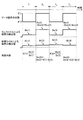
図10は、変形例4−2に係る位置検出システムの各部の動作タイミングを示すチャートである。図10に示すように、カプセル型内視鏡10においては、マーカコイル141に対し、間欠的に通電して駆動させることにより、交番磁界を間欠的に発生させても良い。この場合、マーカ磁界がオフの間に補正係数Kを取得し、マーカ磁界がオンの間に、直前に取得された補正係数Kを用いてセンスコイル32により検出された磁界の検出値の補正をする。(Modification 4-2)
Next, Modification 4-2 of
FIG. 10 is a chart showing the operation timing of each part of the position detection system according to Modification 4-2. As shown in FIG. 10, in the
例えば図10に示すように、時間ΔTごとにマーカ磁界のオン/オフを切り替える場合を考える。以下の説明において、期間T1、T2、T3、T4の長さはそれぞれΔTである。マーカ磁界がオフの期間T1において、演算部71は、センスコイル32により検出された磁界の検出値Bs(1)と参照コイル42による環境磁界の検出値Br(1)とから、補正係数K(1)=Bs(1)/Br(1)を算出する。For example, as shown in FIG. 10, a case where the marker magnetic field is switched on / off at every time ΔT is considered. In the following description, the lengths of the periods T 1 , T 2 , T 3 , and T 4 are ΔT, respectively. In the period T 1 when the marker magnetic field is off, the calculation unit 71 calculates a correction coefficient K from the detected value Bs (1) of the magnetic field detected by the
続く期間T2において、マーカ磁界はオンになる。この間、演算部71は、センスコイル32により検出された磁界の検出値Bs(2)と参照コイル42による環境磁界の検出値Br(2)と、直前に算出された補正係数K(1)とから、上述した式(2)によって与えられるマーカ磁界成分Bm(2)を算出する。さらに演算部71は、マーカ磁界成分Bm(2)に基づいてカプセル型内視鏡10の位置及び方向を算出する。In the subsequent period T 2, the marker field is turned on. During this time, the calculation unit 71 detects the magnetic field detection value Bs (2) detected by the
続く期間T3において、マーカ磁界はオフになる。この間、演算部71は、センスコイル32により検出された磁界の検出値Bs(3)と参照コイル42による環境磁界の検出値Br(3)とから、補正係数K(3)=Bs(3)/Br(3)を算出する。In the subsequent period T 3 , the marker magnetic field is turned off. During this time, the calculation unit 71 calculates the correction coefficient K (3) = Bs (3) from the detected value Bs (3) of the magnetic field detected by the
続く期間T4において、マーカ磁界はオンになる。この間、演算部71は、センスコイル32により検出された磁界の検出値Bs(4)と参照コイル42による環境磁界の検出値Br(4)と、直前に算出された補正係数K(3)とから、式(2)によって与えられるマーカ磁界成分Bm(4)を算出し、さらに、カプセル型内視鏡10の位置及び方向を算出する。In the subsequent period T 4 , the marker magnetic field is turned on. During this time, the calculation unit 71 detects the magnetic field detection value Bs (4) detected by the
このような動作を繰り返すことにより、補正係数K(i)(i=1、2、…)は期間2ΔTごとに更新され、マーカ磁界がオンの期間においては、常に最新の補正係数K(n)を用いた演算が行われる。それにより、環境磁界に時間的な変化が生じたとしても、その変化による影響を最小限に抑制することができる。従って、センスコイル32により検出された磁界の検出値Bs(i)から環境磁界成分Bns(i)を精度良く除去し、カプセル型内視鏡10の位置検出精度を向上させることが可能となる。
By repeating such an operation, the correction coefficient K (i) (i = 1, 2,...) Is updated every period 2ΔT, and the latest correction coefficient K (n) is always updated during the period in which the marker magnetic field is on. An operation using is performed. Thereby, even if a temporal change occurs in the environmental magnetic field, the influence due to the change can be minimized. Therefore, it is possible to accurately remove the environmental magnetic field component Bns (i) from the detected value Bs (i) of the magnetic field detected by the
また、本変形例4−2によれば、マーカコイル141を間欠的に駆動することにより、カプセル型内視鏡10における電力の消費を抑制することができるという効果も得られる。
Moreover, according to this modification 4-2, the effect that the consumption of the electric power in the
(変形例4−3)
次に、本発明の実施の形態4の変形例4−3について説明する。
変形例4−2と異なり、マーカコイル141を連続的に駆動する場合には、補正係数Kを取得するタイミングを以下の例(1)〜(4)のようにして設定しても良い。(Modification 4-3)
Next, Modification 4-3 of
Unlike the modification 4-2, when the
(1)カプセル型内視鏡10による検査の開始後においては、カプセル型内視鏡10が導入された被検体100を、一時的に検出対象領域Rから遠ざける。例えば、ベッド20にスライド式の移動機構を設け、被検体100の体位を変換する際などにベッド20をスライドさせ、検出対象領域Rから被検体100を退避させても良い。この間に補正係数Kを取得する。
(1) After the examination by the
(2)検出対象領域Rとセンスコイルユニット30との間に、磁気シールドを一時的に挿入し、センスコイルユニット30に対してマーカ磁界を遮蔽する。この間に補正係数Kを取得する。
(2) A magnetic shield is temporarily inserted between the detection target region R and the
(3)検出対象領域Rとセンスコイルユニット30との間に、マーカ磁界をキャンセル可能なキャンセルコイルを配置し、ショートとオープンを定期的に又は随時切り替える。そして、キャンセルコイルがショートの間に補正係数Kを取得する。
(3) A cancel coil capable of canceling the marker magnetic field is disposed between the detection target region R and the
(4)パネル31上に配置された複数のセンスコイル32のうち、カプセル型内視鏡10の位置に応じて変化するマーカ磁界の強度が略ゼロになるセンスコイル32に対してのみ、補正係数Kを逐次更新する。
(4) Among the plurality of sense coils 32 arranged on the
(変形例4−4)
次に、本発明の実施の形態4の変形例4−4について説明する。
カプセル型内視鏡を用いた検査の開始後においては、センスコイル32及び参照コイル42がマーカ磁界を検出できない位置、又は検出値が閾値Th(実施の形態1参照)以下となる位置にカプセル型内視鏡を誘導した上で、補正係数Kを取得しても良い。以下、カプセル型内視鏡の誘導操作が可能な位置検出システムを説明する。(Modification 4-4)
Next, Modification 4-4 of
After the start of the examination using the capsule endoscope, the capsule type is placed at a position where the
図11は、変形例4−4に係る位置検出システムの構成を示す模式図である。図11に示す位置検出システム5は、カプセル型内視鏡10Aと、センスコイルユニット30と、参照コイルユニット40と、カプセル型内視鏡10Aを誘導するための磁界を発生する誘導用磁界発生部80と、位置検出装置85とを備える。このうち、センスコイルユニット30及び参照コイルユニット40の構成及び動作は、実施の形態1と同様である。
FIG. 11 is a schematic diagram illustrating a configuration of a position detection system according to Modification 4-4. A
図12は、カプセル型内視鏡10Aの内部構成の一例を示す模式図である。カプセル型内視鏡10Aは、図2に示すカプセル型内視鏡10に対し、内部に永久磁石16を固定配置したものである。永久磁石16は、例えば、磁化方向がカプセル型内視鏡10Aの長軸Laと直交するように配置される。永久磁石16は、外部から印加された磁界に追従して動作する。この結果、誘導用磁界発生部80によるカプセル型内視鏡10Aの誘導が実現する。
FIG. 12 is a schematic diagram illustrating an example of the internal configuration of the
図13は、誘導用磁界発生部80の構成例を示す模式図である。図13に示すように、誘導用磁界発生部80は、カプセル型内視鏡10Aの位置及び方向を変化させるための誘導磁界を、検出対象領域Rを含む空間に生成する。より詳細には、誘導用磁界発生部80は、磁界を発生する体外永久磁石81と、該体外永久磁石81の位置及び姿勢を変化させる磁石駆動部82とを備える。
FIG. 13 is a schematic diagram illustrating a configuration example of the guidance magnetic
体外永久磁石81は、好ましくは、直方体形状を有する棒磁石によって構成され、自身の磁化方向と平行な4つの面の内の1つの面PLと対向する領域内にカプセル型内視鏡10Aを拘束する。
The extracorporeal
磁石駆動部82は、平面位置変更部821、鉛直位置変更部822、仰角変更部823、及び旋回角変更部824を有する。平面位置変更部821は、体外永久磁石81をXY面内において並進させる。鉛直位置変更部822は、体外永久磁石81をZ方向に沿って並進させる。仰角変更部823は、体外永久磁石81の磁化方向を含む鉛直面内において、体外永久磁石81をYc軸回りに回転させる。旋回角変更部824は、体外永久磁石81の中心を通る鉛直方向の軸に対して体外永久磁石81を回転させる。
The
このような磁石駆動部82によって体外永久磁石81を移動及び回転させることにより、体外永久磁石81が発生する磁界に拘束されたカプセル型内視鏡10Aが被検体100内において移動し、撮像視野FV(図12参照)の方向を変化させる。
By moving and rotating the extracorporeal
位置検出装置85は、誘導用磁界制御部861を含む制御部86を備える。誘導用磁界制御部861は、操作入力部52から入力される操作信号に従って磁石駆動部82を制御するための制御情報を生成し、出力する。
The
位置検出システム5において補正係数Kを取得する際には、操作入力部52を操作して、センスコイル32及び参照コイル42が検出するマーカ磁界が最小又は閾値Th以下となる位置にカプセル型内視鏡10Aを誘導する。なお、このときのカプセル型内視鏡10Aの位置は、カプセル型内視鏡10Aの検査開始前に予め決定しておく。ここで、カプセル型内視鏡10Aの誘導中には、カプセル型内視鏡10A内の永久磁石16や誘導用磁界発生部80の体外永久磁石81が動くため、センスコイル32及び参照コイル42はこれらの永久磁石の磁界成分を含む磁界を検出する。しかしながら、マーカ磁界検出部55により、検出した磁界からマーカ磁界成分のみを抽出することができるので、この状態でセンスコイル32及び参照コイル42により検出された磁界の検出値を取得し、補正係数Kを算出すれば良い。
When the correction coefficient K is acquired in the
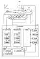
(実施の形態5)
次に、本発明の実施の形態5について説明する。
図14は、本発明の実施の形態5に係る位置検出システムの構成を示す模式図である。図14に示すように、実施の形態5に係る位置検出システム6は、カプセル型内視鏡10と、センスコイルユニット30と、位置検出装置90とを備える。このうち、カプセル型内視鏡10の構成及び動作は、実施の形態1と同様である。また、センスコイルユニット30の構成は実施の形態1と同様であるが、実施の形態5においては、センスコイルユニット30が備える各センスコイル32から出力された検出信号を参照信号としても用いる。(Embodiment 5)
Next, a fifth embodiment of the present invention will be described.
FIG. 14 is a schematic diagram showing a configuration of a position detection system according to
位置検出装置90は、図1に示す制御部58及び環境磁界検出部56の代わりに、制御部91及び環境磁界検出部92をそれぞれ備える。制御部91は、複数のセンスコイル32のうちから、参照信号として用いる検出信号を取り込むコイルを選択するコイル選択部911を有する。また、環境磁界検出部92は、コイル選択部911により選択されたセンスコイル32から検出信号を取り込み、選択されたセンスコイル32の位置における環境磁界の検出値を取得する。なお、制御部91及び環境磁界検出部92以外の位置検出装置90各部の構成及び動作は、実施の形態1と同様である。
The
次に、位置検出システム6の動作について説明する。位置検出システム6の動作は全体として実施の形態1(図4参照)と同様であり、ステップS13における詳細な動作が実施の形態1と異なる。
Next, the operation of the
ステップS12に続くステップS13において、位置検出装置90は、センスコイルユニット30により検出された磁界の検出値を取得する。この際、コイル選択部911は、直前に検出されたカプセル型内視鏡10の位置情報に基づき、複数のセンスコイル32のうち、カプセル型内視鏡10から位置が最も離れたセンスコイル32を選択する。言い換えると、マーカコイル141が発生したマーカ磁界の影響が最も少ないセンスコイル32を選択する。
In step S <b> 13 subsequent to step S <b> 12, the
環境磁界検出部92は、選択されたセンスコイル32から検出信号(参照信号)を取り込み、所定の処理を施すことにより、磁界の参照値を取得する。なお、検出信号に対する処理は、実施の形態1と同様である。この参照値においては、選択されなかったセンスコイル32と比較して、マーカ磁界成分が最も少なく、環境磁界成分が最も多い。即ち、SN比が低い。なお、マーカ磁界検出部55の動作は、実施の形態1と同様である。
The environmental magnetic
続くステップS14において、演算部57は、ステップS13において取得した参照値を用いて、センスコイルユニット30の各センスコイル32のうち、ステップS13において選択されたセンスコイル32以外のセンスコイル32により検出された磁界の検出値を補正する。ステップS15以降の動作は、実施の形態1と同様である。
In subsequent step S14, the
以上説明したように、実施の形態5によれば、参照信号を取得するための専用の参照コイルユニットを設ける必要がなくなるので、位置検出システムの構成を簡素化することが可能となる。 As described above, according to the fifth embodiment, it is not necessary to provide a dedicated reference coil unit for acquiring a reference signal, so that the configuration of the position detection system can be simplified.
また、実施の形態5においては、センスコイルユニット30内の1つのセンスコイル32を参照用として用いるので、参照用として選択されたセンスコイル32と、それ以外のセンスコイル32との間における環境磁界の相関が、別途参照コイルユニットを設ける場合と比較して大きい。従って、式(1)によって与えられるマーカ磁界成分Bmの誤差を小さくすることができる。このとき、マーカコイル141と位置が最も離れたセンスコイル32を参照用として選択することにより、参照値に含まれるマーカ磁界成分を低減し、式(1)によって与えられるマーカ磁界成分BmのSN比低下を抑制することができる。
In the fifth embodiment, since one
なお、実施の形態5においても、変形例1−1と同様に、センスコイル32の一部又は全部を3軸コイルに変更しても良い(図5参照)。この場合、参照信号を取り込むコイルとして3軸コイル(コイルセット33)が選択されたときには、環境磁界検出部92は、コイルセット33に含まれる各センスコイル32X、32Y、32Zから検出信号(参照信号)を取り込み、X、Y、Zの各方向における磁界の参照値を取得しても良い。
Also in the fifth embodiment, a part or all of the
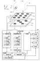
(実施の形態6)
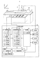
図15は、本発明の実施の形態6に係る位置検出システムの構成を示す模式図である。図15に示すように、実施の形態6に係る位置検出システム201は、カプセル型内視鏡10と、被検体100が載置されるベッド20の下方に設けられた検出コイルユニット230と、該検出コイルユニット230の近傍に設けられた参照コイルユニット240と、カプセル型内視鏡10の位置を検出する位置検出装置250とを備える。本実施の形態6においては、参照コイルユニット240を検出コイルユニット230の下方に配置している。(Embodiment 6)
FIG. 15 is a schematic diagram showing a configuration of a position detection system according to
図16は、図15に示す検出コイルユニット230及び参照コイルユニット240の拡大図である。検出コイルユニット230及び参照コイルユニット240は、検出対象領域Rの鉛直方向の中心軸AZに中心を合わせて配置されている。FIG. 16 is an enlarged view of the
検出コイルユニット230は、ベッド20の上面と平行に配置された平面状のパネル31と、該パネル31の主面上に配置された複数(図16においては9つ)の検出コイルCsn(n=1、2、…、N;図16においてはN=9)とを有する。各検出コイルCsnは、例えば、開口径が30〜40mm程度、高さが5mm程度のサイズを有するコイルバネ状の筒型コイルである。各検出コイルCsnは、カプセル型内視鏡10のマーカコイル(磁界発生コイル)141が発生したマーカ磁界を受信して検出信号を出力する。The
パネル31において、複数の検出コイルCsnは各々の中心軸AsがZ方向と平行になるように、マトリックス状に配置されている。本実施の形態6においても、複数の検出コイルCsnの配置は特に限定されないが、好ましくは、パネル31の中心に対して対称(線対称又は回転対称)となるように配置すると良い。それにより、複数の検出コイルCsnが検出対象領域Rの中心軸Azに対して対称となる。In
参照コイルユニット240は、パネル31と平行に配置された平面状のパネル41と、該パネル41の主面上に配置された参照コイルCeとを有する。参照コイルCeは、検出コイルCsnと同様の筒型コイルであり、マーカ磁界の検出空間を含む当該位置検出システム201の設置環境に存在する環境磁界を検出して検出信号を出力する。以下、参照コイルCeが出力する検出信号を、参照信号という。参照コイルCeは、検出コイルCsnと同様、中心軸AeがZ方向と平行になるように配置されている。The
参照コイルCeは、パネル41の中心(即ち、中心軸Azの延長上)に近づけて配置することが好ましい。パネル41の中心であれば、参照コイルCeと各検出コイルCsnとの距離が概ね均一となり、参照コイルCeに対して極端に近い又は極端に遠い検出コイルCsnがなくなるからである。Reference coil Ce, the center of the panel 41 (i.e., on an extension of the central axis A z) is preferably disposed close to the. This is because at the center of the
次に、検出コイルユニット230と参照コイルユニット240との位置関係について説明する。検出コイルユニット230は、カプセル型内視鏡10が発生するマーカ磁界に対するSN比が高くなるように、検査中の被検体100の近傍に配置される。実施の形態6において、検出コイルユニット230は、ベッド20の下方に配置される。
Next, the positional relationship between the
また、参照コイルユニット240は、各検出コイルCsnの位置における環境磁界を検出するため、検出コイルユニット230にできるだけ近づけて配置すると良い。図16において、参照コイルユニット240は検出コイルユニット230の直下に配置されている。検出コイルCsnが配置されるパネル31と参照コイルCeが配置されるパネル41との距離は短い方が好ましい。Further, the
再び図15を参照すると、位置検出装置250は、受信部51と、操作入力部52と、出力部53と、記憶部54と、各検出コイルCsnから出力された検出信号に対して種々の信号処理を施すマーカ磁界検出部255と、参照コイルCeから出力された参照信号に対して種々の信号処理を施す環境磁界検出部256と、演算部257と、これらの各部の動作を制御する制御部58とを備える。Referring to FIG. 15 again, the position detection device 250 has various types of detection signals output from the
マーカ磁界検出部255は、各検出コイルCsnから出力された検出信号を処理する複数の信号処理チャネルを備える。各信号処理チャネルは、検出信号を増幅する増幅部2551と、検出信号にA/D変換処理を施すA/D変換部2552と、A/D変換部2552から出力されたデジタルの検出信号にFFT処理を施すFFT処理部2553とを有する。The marker magnetic
環境磁界検出部256は、参照コイルCeから出力された参照信号を増幅する増幅部2561と、参照信号にA/D変換処理を施すA/D変換部2562と、A/D変換部2562から出力されたデジタルの参照信号にFFT処理を施すFFT処理部2563とを有する。
The environmental magnetic
演算部257は、例えばCPU等を用いて構成され、記憶部54に記憶されたプログラムを読み込み、所定の演算処理を行う。より詳細には、演算部257は、磁界補正部2571と、位置・方向算出部2572と、画像処理部573とを含む。
The
磁界補正部2571は、環境磁界検出部256から出力された参照信号を用いて、マーカ磁界検出部255の各信号処理チャネルから出力された検出信号の出力値を補正することにより、環境磁界の影響が除去されたマーカ磁界成分の値(補正値)を出力する。
The magnetic
図17は、磁界補正部2571の構成を示すブロック図である。磁界補正部2571は、検出コイルCsnに対応する複数のチャネルChn(n=1、2、…、N)を備える。各チャネルChnは、検出コイルCsnから出力され、マーカ磁界検出部255の対応する信号処理チャネルにおいて所定の信号処理が施された検出信号を、環境磁界検出部256から出力された参照信号を用いて補正する処理を実行する。FIG. 17 is a block diagram showing the configuration of the magnetic
詳細には、各チャネルChnは、検出コイル環境磁界抽出部1aと、参照コイル環境磁界抽出部1bと、参照コイル環境磁界算出部1cと、環境磁界比率算出部1dと、検出コイル環境磁界算出部1eと、マーカ磁界成分算出部1fとを備える。Specifically, each channel Ch n includes a detection coil environmental magnetic field extraction unit 1a, a reference coil environmental magnetic
検出コイル環境磁界抽出部(第1フィルタ)1aは、検出信号Smに対してハイパス(低域除去)フィルタ処理を施すことにより、検出信号Smに含まれる環境磁界成分(第1の周波数帯域成分)を抽出し、この環境磁界成分の値(第1の値)Esを出力する。 The detection coil environmental magnetic field extraction unit (first filter) 1a performs high-pass (low-frequency elimination) filter processing on the detection signal Sm, thereby causing an environmental magnetic field component (first frequency band component) included in the detection signal Sm. And the value (first value) Es of the environmental magnetic field component is output.
参照コイル環境磁界抽出部(第2フィルタ)1bは、参照信号Srに対してハイパスフィルタ処理を施すことにより、参照信号Srに含まれる環境磁界成分(第1周波数帯域成分)を抽出し、この環境磁界成分の値(第2の値)Erを出力する。 The reference coil environmental magnetic field extraction unit (second filter) 1b performs high-pass filter processing on the reference signal Sr to extract an environmental magnetic field component (first frequency band component) included in the reference signal Sr. The value (second value) Er of the magnetic field component is output.
参照コイル環境磁界算出部(第3フィルタ)1cは、参照信号Srに対して、参照コイル環境磁界抽出部1bとは異なるカットオフ周波数のハイパスフィルタ処理を施すことにより環境磁界成分(第2周波数帯域成分)を抽出し、この環境磁界成分の値(第3の値)Er’を算出する。
The reference coil environmental magnetic field calculation unit (third filter) 1c performs high-pass filter processing with a cut-off frequency different from that of the reference coil environmental magnetic
環境磁界比率算出部1dは、検出コイル環境磁界抽出部1aにより抽出された環境磁界成分の値Esと、参照コイル環境磁界抽出部1bにより抽出された環境磁界成分の値Erとの比率κを算出する。
The environmental magnetic field ratio calculation unit 1d calculates a ratio κ between the environmental magnetic field component value Es extracted by the detection coil environmental magnetic field extraction unit 1a and the environmental magnetic field component value Er extracted by the reference coil environmental magnetic
検出コイル環境磁界算出部1eは、比率κと参照コイル環境磁界算出部1cから出力された環境磁界成分の値Er’とから、検出信号Smに含まれる環境磁界成分の値Es’を算出する。 The detection coil environmental magnetic field calculation unit 1e calculates an environmental magnetic field component value Es 'included in the detection signal Sm from the ratio κ and the environmental magnetic field component value Er' output from the reference coil environmental magnetic field calculation unit 1c.
マーカ磁界成分算出部1fは、検出信号Smの出力値から環境磁界成分の値Es’を減算することにより、検出信号Smに含まれるマーカ磁界成分の値Msを算出する。 The marker magnetic field component calculation unit 1f calculates the marker magnetic field component value Ms included in the detection signal Sm by subtracting the environmental magnetic field component value Es' from the output value of the detection signal Sm.
再び図15を参照すると、位置・方向算出部2572は、磁界補正部2571の各チャネルChnから出力されたマーカ磁界成分の値Msに基づいて、カプセル型内視鏡10の位置及び方向(カプセル型内視鏡10の長軸LaのX、Y、Z方向における傾き)を算出する。以下、カプセル型内視鏡10の位置及び方向に関する情報をまとめて、位置情報ともいう。Referring to FIG. 15 again, the position /
次に、本実施の形態6における位置検出方法について説明する。図18〜図20は、本実施の形態6における位置検出方法を説明するためのグラフである。このうち、図18の(a)及び図19の(a)は、異なる2つの検出コイルCsnから出力された検出信号Smにそれぞれ含まれるマーカ磁界成分の値Msを示し、図18の(b)及び図19の(b)は、同検出信号にそれぞれ含まれる環境磁界成分の値Esを示し、図18の(c)及び図19の(c)は、同検出信号Smの出力値(マーカ磁界成分の値Msと環境磁界成分の値Esとの和)を示す。図20の(a)は、参照コイルCeから出力された参照信号Srに含まれるマーカ磁界成分の値Mrを示し、図20の(b)は、同参照信号に含まれる環境磁界成分の値Erを示し、図20の(c)は、参照信号Srの出力値(マーカ磁界成分の値Mrと環境磁界成分の値Erとの和)を示す。Next, a position detection method according to the sixth embodiment will be described. 18 to 20 are graphs for explaining the position detection method according to the sixth embodiment. Among these, (a) in FIG. 18 and (a) in FIG. 19 show the value Ms of the marker magnetic field component included in each of the detection signals Sm output from two different detection coils Cs n , and FIG. ) And FIG. 19B show the values Es of the environmental magnetic field components included in the detection signal, respectively, and FIGS. 18C and 19C show the output value (marker) of the detection signal Sm. (Sum of magnetic field component value Ms and environmental magnetic field component value Es). 20A shows the value Mr of the marker magnetic field component included in the reference signal Sr output from the reference coil Ce, and FIG. 20B shows the value Er of the environmental magnetic field component included in the reference signal. FIG. 20C shows the output value of the reference signal Sr (the sum of the marker magnetic field component value Mr and the environmental magnetic field component value Er).
ここで、検出信号Smに対して精度の良い補正を行うためには、図16に示すように、参照コイルユニット240をできるだけ検出コイルユニット230に近づけて配置し、検出コイルCsnの位置における環境磁界と参照コイルCeの位置における環境磁界との相関を高めることが好ましい。しかし、この場合、図20に示すように、参照コイルCeは、環境磁界に加えて、検出コイルCsn近傍のマーカ磁界も検出してしまう。Here, in order to perform accurate correction with respect to the detection signal Sm, as shown in FIG. 16, located close to the only the
図18及び図19に示すように、検出コイルCsnから出力される検出信号Smに含まれるマーカ磁界成分の値Msは、検出コイルCsnの位置に応じて大きく異なる。また、各検出信号Smにおけるマーカ磁界成分の値Msは、周波数が高くなるほど小さくなる。As shown in FIGS. 18 and 19, the value Ms of the marker field component contained in the detection signal Sm outputted from the sensor coil Cs n may vary greatly depending on the position of the detection coil Cs n. Further, the value Ms of the marker magnetic field component in each detection signal Sm decreases as the frequency increases.
一方、検出信号Smに含まれる環境磁界成分の値Esは、検出コイルCsnの位置によらず、ほぼ一定となる。また、各検出信号Smにおける環境磁界成分の値Esは、周波数の高低によらず、ほぼ一定となる。On the other hand, the value Es of the environmental magnetic field component included in the detection signal Sm is substantially constant regardless of the position of the detection coil Cs n . Further, the value Es of the environmental magnetic field component in each detection signal Sm is substantially constant regardless of the frequency.
このようなマーカ磁界成分及び環境磁界成分の傾向は、図20に示すように、参照信号Srにおいても同様である。そこで、本実施の形態6においては、マーカ磁界と環境磁界との周波数の違いを利用して、検出信号Sm及び参照信号Srにハイパスフィルタ処理を施すことにより、マーカ磁界成分と環境磁界成分とを分離する。そして、参照信号Srに含まれるマーカ磁界成分を除去した環境磁界成分の値を用いて、検出信号Smの出力値の補正を行う。 The tendency of the marker magnetic field component and the environmental magnetic field component is the same in the reference signal Sr as shown in FIG. Thus, in the sixth embodiment, the marker magnetic field component and the environmental magnetic field component are obtained by performing high-pass filter processing on the detection signal Sm and the reference signal Sr using the difference in frequency between the marker magnetic field and the environmental magnetic field. To separate. Then, the output value of the detection signal Sm is corrected using the value of the environmental magnetic field component from which the marker magnetic field component included in the reference signal Sr is removed.
以下、各チャネルChnにおける処理を詳細に説明する。まず、磁界補正部2571は、カプセル型内視鏡10の動きによって決定されるマーカ磁界の最大周波数Fmaxを、検出コイル環境磁界抽出部1a及び参照コイル環境磁界抽出部1bにおけるカットオフ周波数に設定する。Hereinafter, processing in each channel Ch n will be described in detail. First, the magnetic
検出コイル環境磁界抽出部1aは、検出信号Smに対し、上記最大周波数Fmaxをカットオフ周波数としてハイパスフィルタ処理を施すことにより、環境磁界成分を抽出する。The detection coil environmental magnetic field extraction unit 1a extracts an environmental magnetic field component by performing high-pass filter processing on the detection signal Sm with the maximum frequency F max as a cutoff frequency.
また、参照コイル環境磁界抽出部1bは、参照信号Srに対し、上記最大周波数Fmaxをカットオフ周波数としてハイパスフィルタ処理を施すことにより、環境磁界成分を抽出する。Further, the reference coil environmental magnetic
そして、環境磁界比率算出部1dは、検出信号Smから抽出された環境磁界成分の値Esと、参照信号Srから抽出された環境磁界成分の値Erとの比率κを算出する。好ましくは、検出信号Smから抽出された高周波数帯域成分の値の標準偏差σEsと、参照信号Srから抽出された高周波数帯域成分の値の標準偏差σEsとの比σEs/σEsを、比率κとすると良い。Then, the environmental magnetic field ratio calculation unit 1d calculates a ratio κ between the value Es of the environmental magnetic field component extracted from the detection signal Sm and the value Er of the environmental magnetic field component extracted from the reference signal Sr. Preferably, a ratio σ Es / σ Es between the standard deviation σ Es of the value of the high frequency band component extracted from the detection signal Sm and the standard deviation σ Es of the value of the high frequency band component extracted from the reference signal Sr is set. The ratio κ is good.
ここで、図21を参照しながら、検出コイル環境磁界抽出部1a及び参照コイル環境磁界抽出部1bにおけるカットオフ周波数を最大周波数Fmaxに設定する理由を説明する。図21は、検出コイルCsn又は参照コイルCeから出力される検出信号Sm又は参照信号Srの出力値OSを示すグラフである。Here, the reason why the cutoff frequency in the detection coil environment magnetic field extraction unit 1a and the reference coil environment magnetic
磁界の検出信号Sm又は参照信号Srにハイパスフィルタ処理を施すことにより、環境磁界成分を抽出する場合を考える。環境磁界をホワイトノイズと仮定すると、図21の(a)、(b)に示すように、全環境磁界成分(領域p1の面積に相当)に対し、ハイパスフィルタ処理を施すことによりカットされる(減少する)環境磁界成分(領域p2の面積に相当)の比率は、カットオフ周波数Fcによって決まる。Consider a case where an environmental magnetic field component is extracted by performing high-pass filtering on the magnetic field detection signal Sm or the reference signal Sr. Assuming that the environmental magnetic field is white noise, as shown in FIGS. 21A and 21B, the entire environmental magnetic field component (corresponding to the area of the region p1) is cut by applying a high-pass filter process ( The ratio of the environmental magnetic field component (corresponding to the area of the region p2) to be reduced is determined by the cutoff frequency F c .
また、図21の(b)、(c)に示すように、カットオフ周波数Fcが同一である場合、全環境磁界成分に対する環境磁界の減少成分の比率は、マーカ磁界の大きさによらずほぼ一定である。即ち、カットオフ周波数Fcが同一であれば、複数の検出信号及び参照信号の間において環境磁界の減少成分の比率は一定になるため、環境磁界の減少成分は、検出信号及び参照信号からそれぞれ抽出される環境磁界成分同士の比率κに影響を与えない。そこで、マーカ磁界の残留成分がゼロとなる最大周波数Fmaxをカットオフ周波数Fcとすることにより、比率κを正確に算出することができる。Further, as shown in FIGS. 21B and 21C, when the cut-off frequency F c is the same, the ratio of the decrease component of the environmental magnetic field to the total environmental magnetic field component does not depend on the magnitude of the marker magnetic field. It is almost constant. That is, if the cutoff frequency F c is the same, the ratio of the environmental magnetic field reduction component is constant between the plurality of detection signals and the reference signal, and therefore the environmental magnetic field reduction component is determined from the detection signal and the reference signal, respectively. The ratio κ between the extracted environmental magnetic field components is not affected. Therefore, the ratio κ can be accurately calculated by setting the maximum frequency F max at which the residual component of the marker magnetic field is zero as the cutoff frequency F c .
なお、実際に磁界を検出する際には、環境磁界以外にも、ハードウェアに起因するノイズなど、環境磁界よりも小さいノイズ成分が混入する。このような小さいノイズ成分を無視するため、環境磁界成分の値として、フィルタ処理により抽出された周波数帯域成分の値の標準偏差を用いても良い。 When actually detecting a magnetic field, in addition to the environmental magnetic field, a noise component smaller than the environmental magnetic field, such as noise caused by hardware, is mixed. In order to ignore such a small noise component, the standard deviation of the value of the frequency band component extracted by the filtering process may be used as the value of the environmental magnetic field component.
この最大周波数Fmaxは、カプセル型内視鏡10の位置検出結果から取得されるカプセル型内視鏡10の最大移動速度vを用いて算出することができる。ここで、マーカ磁界の周波数fを変数とするカプセル型内視鏡10の変位G(f)は、次式(3)によって与えられる。
G(f)=v/(2πf)2 …(3)The maximum frequency F max can be calculated using the maximum moving speed v of the
G (f) = v / (2πf) 2 (3)
この式(3)において、変位Gが十分に小さくなる周波数fを最大周波数Fmaxとして決定する。実際には、許容可能な位置誤差の上限を閾値として予め設定し、変位Gが閾値以下となる周波数fを求めれば良い。In this equation (3), the frequency f at which the displacement G becomes sufficiently small is determined as the maximum frequency F max . Actually, an upper limit of an allowable position error is set in advance as a threshold value, and a frequency f at which the displacement G is equal to or less than the threshold value may be obtained.
一方、磁界補正部2571は、上記最大周波数Fmaxよりも小さい周波数Fc(Fc<Fmax)を、参照コイル環境磁界算出部1cにおけるカットオフ周波数に設定する。参照コイル環境磁界算出部1cは、参照信号Srに対し、このカットオフ周波数Fcでハイパスフィルタ処理を施すことにより、環境磁界成分の値Er’を算出する。On the other hand, the magnetic
ここで、図21を参照しながら、環境磁界成分の値Er’を算出する際のカットオフ周波数Fcの決定方法を説明する。カットオフ周波数Fcを最大周波数Fmax以上に設定する場合、マーカ磁界の残留成分はゼロになる。また、図21の(a)に示すように、カットオフ周波数Fcを最大周波数Fmax未満に設定する場合、マーカ磁界の残留成分(領域qの面積に相当)は、カットオフ周波数Fcが小さくなるにつれて増加する。図21の(b)及び(c)に示すように、カットオフ周波数Fcが同一である場合、マーカ磁界の残留成分(同上)は、マーカ磁界成分の強さに比例する。Here, a method for determining the cutoff frequency F c when calculating the value Er ′ of the environmental magnetic field component will be described with reference to FIG. When the cutoff frequency F c is set to be equal to or higher than the maximum frequency F max , the marker magnetic field residual component becomes zero. As shown in FIG. 21A, when the cutoff frequency F c is set to be lower than the maximum frequency F max , the residual component of the marker magnetic field (corresponding to the area of the region q) is the cutoff frequency F c. It increases as it gets smaller. As shown in FIGS. 21B and 21C, when the cutoff frequency F c is the same, the residual component (same as above) of the marker magnetic field is proportional to the strength of the marker magnetic field component.
一方、ハイパスフィルタ処理を施すことによりカットされる環境磁界の減少成分(領域p2の面積)は、カットオフ周波数Fcが大きくなるほど増加する。On the other hand, the decreasing component (area of the region p2) of the environmental magnetic field that is cut by performing the high-pass filter processing increases as the cutoff frequency F c increases.
参照信号から環境磁界成分を抽出する場合、その抽出誤差は、マーカ磁界の残留成分と、環境磁界の減少成分との和に等しい。従って、マーカ磁界の残留成分と環境磁界の減少成分との和が最小となるように、カットオフ周波数Fcを決定する。好ましくは、マーカ磁界の残留成分の強さと、環境磁界の減少成分との強さが等しくなるように、カットオフ周波数Fcを決定すると良い。これは、図21の(a)に示すように、領域p2の面積と領域qの面積とが等しくなるように周波数Fcを決定することに相当する。それにより、環境磁界成分の抽出誤差を低減することができる。参照信号に含まれるマーカ磁界の残留成分と環境磁界成分は時間変化するので、マーカ磁界検出部255及び環境磁界検出部256が磁界を検出したタイミングごとにカットオフ周波数Fcを更新する。When extracting the environmental magnetic field component from the reference signal, the extraction error is equal to the sum of the residual component of the marker magnetic field and the decreasing component of the environmental magnetic field. Accordingly, the cutoff frequency F c is determined so that the sum of the residual component of the marker magnetic field and the decrease component of the environmental magnetic field is minimized. Preferably, the cutoff frequency Fc is determined so that the strength of the residual component of the marker magnetic field is equal to the strength of the decreasing component of the environmental magnetic field. This corresponds to determining the frequency F c so that the area of the region p2 is equal to the area of the region q, as shown in FIG. Thereby, the extraction error of the environmental magnetic field component can be reduced. Since the residual component of the marker magnetic field and the environmental magnetic field component included in the reference signal change with time, the cutoff frequency F c is updated at each timing when the marker magnetic
検出コイル環境磁界算出部1eは、このようにして算出された環境磁界成分の値Er’と比率κとの積を、検出コイルCsnの位置における環境磁界成分の値Es’として算出する。The detection coil environmental magnetic field calculation unit 1e calculates the product of the value Er ′ of the environmental magnetic field component thus calculated and the ratio κ as the value Es ′ of the environmental magnetic field component at the position of the detection coil Cs n .
さらに、マーカ磁界成分算出部1fは、検出コイル環境磁界算出部1eが算出した環境磁界成分の値Es’を検出信号Smの出力値から減算することにより、マーカ磁界成分の値Msを算出する。このマーカ磁界成分の値Msが、検出信号の補正値として出力される。 Further, the marker magnetic field component calculation unit 1 f calculates the marker magnetic field component value Ms by subtracting the environmental magnetic field component value Es ′ calculated by the detection coil environmental magnetic field calculation unit 1 e from the output value of the detection signal Sm. The marker magnetic field component value Ms is output as a correction value of the detection signal.
次に、位置検出システム201の動作について、図22を参照しながら説明する。図22は、位置検出システム201の動作を示すフローチャートである。まず、ステップS110において、カプセル型内視鏡10の電源をオンにする。
Next, the operation of the
続くステップS111において、位置検出装置250は、カプセル型内視鏡10から送信された無線信号を受信アンテナ51aにより受信し、該無線信号に復調処理等を施すことにより、無線信号に重畳された体内画像の画像データ及び関連情報等を取得して、画像処理を開始する。
In subsequent step S111, the position detection device 250 receives the radio signal transmitted from the
ステップS112において、位置検出装置250は、複数の検出コイルCsnからそれぞれ出力された検出信号及び参照コイルCeから出力された参照信号を取得し、マーカ磁界検出部255及び環境磁界検出部256において、増幅処理、A/D変換処理、及びFFT処理等の所定の信号処理を施す。In step S112, the position detection device 250 acquires the detection signal output from each of the plurality of detection coils Cs n and the reference signal output from the reference coil Ce, and in the marker magnetic
ステップS113において、磁界補正部2571は、マーカ磁界検出部255から複数の検出信号を取得すると共に、環境磁界検出部256から参照信号を取得し、この参照信号を用いて検出信号の出力値を補正する。即ち、検出信号から環境磁界成分を除去したマーカ磁界成分の値を算出する。
In step S113, the magnetic
ここで、磁界補正部2571は、検出信号の出力値の補正を最初に行う場合、比率κを算出する際のハイパスフィルタ処理のカットオフ周波数として、最大周波数Fmaxの初期値(固定値)を設定する。また、磁界補正部2571は、2回目以降、直前のカプセル型内視鏡10の位置検出結果からカプセル型内視鏡10の単位時間あたりの位置変化量を取得し、この位置変化量の最大値を式(3)における最大移動速度vとして最大周波数Fmaxを算出し、これをカットオフ周波数として設定する。Here, when correcting the output value of the detection signal for the first time, the magnetic
ステップS114において、位置・方向算出部2572は、磁界補正部2571の各チャネルChnから出力された補正値をもとに、カプセル型内視鏡10の位置及び方向を算出する。In step S < b > 114, the position /
ステップS115において、演算部257は、位置・方向算出部2572により算出されたカプセル型内視鏡10の位置及び方向(位置情報)と画像処理部573により画像処理が施された画像データとを関連付けて記憶部54に記憶させる。
In step S115, the
ステップS116において、制御部58は、カプセル型内視鏡10の位置検出を終了するか否かを判定する。詳細には、カプセル型内視鏡10からの無線送信が停止した場合や、位置検出装置250に対して操作入力部52から位置検出動作終了の指示情報が入力された場合に、位置検出を終了すると判定する。なお、カプセル型内視鏡10は、電源部15がオフされるか、又は電池切れになるまで、画像データの無線送信及びマーカ磁界の発生を継続する。
In step S116, the
カプセル型内視鏡10の位置検出を終了しない場合(ステップS116:No)、位置・方向算出部2572は、カプセル型内視鏡10の位置情報を磁界補正部2571に入力する(ステップS117)。その後、位置検出システム201の動作はステップS112に戻る。この場合、続くステップS113においては、カプセル型内視鏡10の位置情報に基づいて最大周波数Fmaxを算出する。一方、位置検出を終了する場合(ステップS116:Yes)、位置検出システム201の動作は終了する。When the position detection of the
以上説明したように、本発明の実施の形態6によれば、カプセル型内視鏡10から発生したマーカ磁界を検出するための検出コイルCsnの近傍に、環境磁界を検出するための参照コイルCeを配置し、検出コイルCsnから出力された検出信号の出力値を参照コイルCeから出力された参照信号を用いて補正するので、検出信号の出力値から短時間に変化する環境磁界成分を除外することができる。As described above, according to the sixth embodiment of the present invention, the reference coil for detecting the environmental magnetic field in the vicinity of the detection coil Cs n for detecting the marker magnetic field generated from the
また、本発明の実施の形態6によれば、検出信号及び参照信号からそれぞれ抽出された環境磁界成分同士の相関(比率κ)を考慮して、検出信号に含まれる環境磁界成分を算出し、この環境磁界成分を用いて検出信号の出力値を補正するので、参照信号の出力値をそのまま用いて検出信号の出力値を補正する場合と比べて、補正精度を向上させることができる。従って、このように補正された値を用いることにより、カプセル型内視鏡10の位置及び方向を、精度良く検出することが可能となる。
Further, according to the sixth embodiment of the present invention, the environmental magnetic field component included in the detection signal is calculated in consideration of the correlation (ratio κ) between the environmental magnetic field components extracted from the detection signal and the reference signal, Since the output value of the detection signal is corrected using the environmental magnetic field component, the correction accuracy can be improved as compared with the case where the output value of the detection signal is corrected using the output value of the reference signal as it is. Therefore, by using the corrected value, the position and direction of the
(変形例6−1)
次に、本発明の実施の形態6の変形例6−1について説明する。図23は、本発明の実施の形態6の変形例6−1に係る位置検出システムの構成を示す模式図である。(Modification 6-1)
Next, Modification 6-1 of
カプセル型内視鏡10の位置検出精度を高めるために、図16に示す検出コイルCsnの一部又は全部を3軸コイルに変更しても良い。例えば図23に示す検出コイルユニット232においては、パネル31の4隅近傍に、3次元的な磁界検出が可能なコイルセット233を設けている。各コイルセット233は、中心軸AsがX方向、Y方向、Z方向とそれぞれ平行な3つの検出コイルCsx、Csy、Cszを含む。各検出コイルCsx、Csy、Cszは、自身の中心軸Asの方向における磁界を検出して検出信号を出力する。なお、各検出コイルCsx、Csy、Cszの構成は、図16に示す検出コイルCsnと同様である。To increase the position detection accuracy of the
この場合、参照信号を出力する参照コイルユニット242においても、検出コイルCsx、Csy、Cszの向きに合わせて、中心軸AeがX方向、Y方向、Z方向とそれぞれ平行な3つの参照コイルCex、Cey、Cezを配置する。各参照コイルCex、Cey、Cezは、自身の中心軸Aeの方向における磁界を検出して参照信号を出力する。なお、各参照コイルCex、Cey、Cezの構成は、図16に示す参照コイルCeと同様である。In this case, also in the reference coil unit 242 that outputs a reference signal, three central axes A e are parallel to the X, Y, and Z directions in accordance with the directions of the detection coils Cs x , Cs y , and Cs z . Reference coils Ce x , Ce y , and Ce z are arranged. Each reference coil Ce x , Ce y , Ce z detects a magnetic field in the direction of its central axis A e and outputs a reference signal. The configuration of each reference coil Ce x , Ce y , Ce z is the same as that of the reference coil Ce shown in FIG.
各参照コイルCex、Cey、Cezは、検出対象領域Rの中心軸Azに対して対称的(線対称又は点対称)に配置することが好ましい。図23においては、参照コイルCex、Cey、Cezを、中心軸Azを通るパネル41の中心線上に配置している。より好ましくは、これらの参照コイルCex、Cey、Cezを、中心軸Azに近づけて配置すると良い。中心軸Az上であれば、参照コイルCex、Cey、Cezと各検出コイルCsnとの距離が概ね均一となり、突出して近い又は突出して遠い検出コイルCsnがなくなるため、環境磁界に局所的な変化が生じたとしても、その影響を抑制することができるからである。Each reference coil Ce x , Ce y , Ce z is preferably arranged symmetrically (line symmetric or point symmetric) with respect to the central axis A z of the detection target region R. In FIG. 23, the reference coils Ce x , Ce y , and Ce z are arranged on the center line of the
このようにコイルセット233を配置する場合、図22のステップS113において検出信号の出力値を補正する際には、検出コイルCsx、Csy、Cszとそれぞれ同じ方向を向く参照コイルCex、Cey、Cezから出力された参照信号を用いて演算を行う。即ち、検出コイルCsxから出力された検出信号に対しては、参照コイルCexから出力された参照信号を用いて補正を行う。検出コイルCsy、Cszについても同様である。それにより、環境磁界の方向に応じた補正を行うことができる。When the coil set 233 is arranged in this way, when correcting the output value of the detection signal in step S113 in FIG. 22, the reference coils Ce x , which are respectively directed in the same direction as the detection coils Cs x , Cs y , Cs z , The calculation is performed using the reference signals output from Ce y and Ce z . That is, for the detection signal outputted from the detection coil Cs x, correction is performed using the reference signal outputted from the reference coil Ce x. The same applies to the detection coils Cs y and Cs z . Thereby, the correction according to the direction of the environmental magnetic field can be performed.
(変形例6−2)
次に、本発明の実施の形態6の変形例6−2について説明する。上記実施の形態6においては、磁界補正部2571に複数のチャネルChnを設け、複数の検出コイルCsnからそれぞれ出力された複数の検出信号をこれらのチャネルChnにおいて並列で処理したが、複数の検出信号を順次処理することとしても良い。この場合、マーカ磁界検出部255から出力された複数の検出信号を一時的に記憶するメモリを設け、このメモリから検出信号を順次読み出し、環境磁界検出部256から出力された参照信号を用いて、環境磁界成分の抽出処理、比率κの算出処理、比率κを用いた環境磁界成分の算出処理、及び、この環境磁界成分を検出信号の出力値から減算するマーカ磁界成分の算出処理を実行し、位置・方向算出部2572に順次出力する。(Modification 6-2)
Next, a modification 6-2 of the sixth embodiment of the present invention will be described. In the sixth embodiment, a plurality of channels Ch n are provided in the magnetic
(実施の形態7)
次に、本発明の実施の形態7について説明する。図24は、本発明の実施の形態7に係る位置検出システムの構成を示す模式図である。図24に示すように、実施の形態7に係る位置検出システム202は、カプセル型内視鏡10と、検出コイルユニット230と、参照コイルユニット243と、位置検出装置260とを備える。このうち、カプセル型内視鏡10及び検出コイルユニット230の構成及び動作は、実施の形態6と同様である。(Embodiment 7)
Next, a seventh embodiment of the present invention will be described. FIG. 24 is a schematic diagram showing a configuration of a position detection system according to Embodiment 7 of the present invention. As shown in FIG. 24, the
参照コイルユニット243は、パネル41と、該パネル41上に配置された複数(図24においては5つ)の参照コイルCem(m=1、2、…M;図24においてはM=5)とを備える。各参照コイルCemの構成及び配置の向きは、図16に示す参照コイルCeと同様である。このような参照コイルユニット243は、検出コイルユニット230の近傍に、検出コイルユニット230と平行に配置されている。The
位置検出装置260は、図15に示す環境磁界検出部256の代わりに環境磁界検出部261を備え、さらに、参照信号選択部262を備える。環境磁界検出部261及び参照信号選択部262以外の位置検出装置260の各部の構成及び動作は、実施の形態6と同様である。
The
環境磁界検出部261は、複数の参照コイルCemから出力された参照信号を処理する複数の信号処理チャネルを有する。各信号処理チャネルは、参照信号を増幅する増幅部2611と、検出信号にA/D変換処理を施すA/D変換部2612と、A/D変換部2612から出力されたデジタルの検出信号にFFT処理を施すFFT処理部2613とを備える。Environmental magnetic field detector 261 includes a plurality of signal processing channels for processing the reference signals output from the plurality of reference coils Ce m. Each signal processing channel includes an
参照信号選択部262は、環境磁界検出部261の複数の信号処理チャネルからそれぞれ出力された複数の参照信号から、磁界補正部2571において使用する参照信号を1つ選択し、磁界補正部2571の各チャネルChn(図17参照)に入力する。具体的には、環境磁界検出部261から出力された複数の参照信号のうち、マーカ磁界成分が最も小さい参照信号を、磁界補正部2571において使用する参照信号として選択する。ここで、図18〜図20に示すように、環境磁界成分の値は信号全体のレベルによらずほぼ一定であり、参照信号のレベルが小さいほどそこに含まれるマーカ磁界成分が少ないため、参照信号に含まれるマーカ磁界成分が検出信号の補正に与える影響を低減できるからである。The reference
次に、位置検出システム202の動作について説明する。図25は、位置検出システム202の動作を示すフローチャートである。このうち、ステップS110〜S112は、実施の形態6と同様である(図22参照)。
Next, the operation of the
ステップS112に続くステップS121において、参照信号選択部262は、環境磁界検出部261の複数の信号処理チャネルからそれぞれ出力された参照信号の信号レベルに基づき、信号レベルが最小の参照信号を選択して、磁界補正部2571の各チャネルChnに出力する。ステップS121に続くステップS113以降の動作は、実施の形態6と同様である。In step S121 following step S112, the reference
以上説明したように、本発明の実施の形態7によれば、複数の参照コイルCemから出力された参照信号の中から、マーカ磁界成分の影響が少ない参照信号を選択して用いるので、検出信号の補正をより精度良く行うことができる。As described above, according to the seventh embodiment of the present invention, from among the reference signals output from the plurality of reference coils Ce m, since selecting and using the reference signal is less affected by the marker field component, detected The signal can be corrected more accurately.
(変形例7)
次に、本発明の実施の形態7の変形例7について説明する。図26は、本発明の実施の形態7の変形例7に係る位置検出システムの構成を示す模式図である。(Modification 7)
Next, Modification 7 of Embodiment 7 of the present invention will be described. FIG. 26 is a schematic diagram showing a configuration of a position detection system according to Modification 7 of Embodiment 7 of the present invention.
実施の形態6の変形例6−1のように、検出コイルユニット232に3軸コイル(コイルセット233)を設ける場合、参照コイルユニット側にも、複数の3軸コイルを設けても良い。図26に示す参照コイルユニット244においては、3つの参照コイルCex、Cey、Cezからなるコイルセット245を、パネル41上に2組設けている。When a triaxial coil (coil set 233) is provided in the
この場合、図25のステップS113において検出信号の出力値を補正する際には、検出コイルCsn、Csx、Csy、Cszとそれぞれ同じ方向を向く参照コイルCex、Cey、Cezから出力された参照信号のうち、信号レベルの小さい参照信号を用いて演算を行う。即ち、検出コイルCsxから出力された検出信号に対しては、2つの参照コイルCexからそれぞれ出力された参照信号のうち、信号レベルが小さい方の参照信号を用いて補正を行う。検出コイルCsy、Cszについても同様である。それにより、環境磁界の方向に応じた補正を行うことができる。In this case, when the output value of the detection signal is corrected in step S113 in FIG. 25, the reference coils Ce x , Ce y , and Ce z that face the same direction as the detection coils Cs n , Cs x , Cs y , and Cs z , respectively. Among the reference signals output from, the calculation is performed using a reference signal having a low signal level. That is, for the detection signal outputted from the detection coil Cs x, among reference signals outputted respectively from the two reference coils Ce x, correction is performed using the reference signal towards the signal level is small. The same applies to the detection coils Cs y and Cs z . Thereby, the correction according to the direction of the environmental magnetic field can be performed.
(実施の形態8)
次に、本発明の実施の形態8について説明する。図27は、本発明の実施の形態8に係る位置検出システムの構成を示す模式図である。図27に示すように、本発明の実施の形態8に係る位置検出システム203は、カプセル型内視鏡10と、検出コイルユニット230と、位置検出装置270とを備える。カプセル型内視鏡10及び検出コイルユニット230の構成及び動作は、実施の形態6と同様である。(Embodiment 8)
Next, an eighth embodiment of the present invention will be described. FIG. 27 is a schematic diagram showing a configuration of a position detection system according to Embodiment 8 of the present invention. As shown in FIG. 27, the
位置検出装置270は、図15に示す位置検出装置250に対し、環境磁界検出部256の代わりに、参照コイル選択部271を備える。参照コイル選択部271は、磁界補正部2571による検出信号の補正結果に基づいて、複数の磁界検出コイルCnsのうちから、参照コイルとして用いる磁界検出コイルCnsを選択する。参照コイル選択部271以外の位置検出装置270の各部の構成及び動作は、実施の形態6と同様である。The
次に、位置検出システム203の動作を説明する。図28は、位置検出システム203の動作を示すフローチャートである。このうち、ステップS110、S111は、実施の形態6と同様である(図22参照)。
Next, the operation of the
ステップS111に続くステップS131において、参照コイル選択部271は、磁界補正部2571から検出信号の補正結果を取得し、マーカ磁界成分が最も小さい検出信号を出力した検出コイルCsnを、参照コイルとして選択する。なお、カプセル型内視鏡10の位置検出がまだ行われていない場合(即ち、初回の動作時)には、参照コイル選択部271は、予め定められた検出コイルCsnを選択する。In step S131 following step S111, the reference
続くステップS132において、マーカ磁界検出部255は、各検出コイルCsnから出力された検出信号を取得し、増幅処理、A/D変換処理、及びFFT処理等の所定の信号処理を施す。In subsequent step S132, the marker magnetic
続くステップS133において、マーカ磁界検出部255は、参照コイル選択部271により選択された検出コイルCsnの検出信号を、磁界補正部2571の各チャネルに参照信号として出力すると共に、それ以外の検出コイルCsnの検出信号を、対応するチャネルChnに出力する。続くステップS113〜S117の動作は、実施の形態6と同様である。ステップS117の後、位置検出システム203の動作はステップS131に戻る。In subsequent step S133, the marker magnetic
以上説明したように、本発明の実施の形態8によれば、複数の検出コイルのうちの1つを参照コイルとして用いるので、検出信号と参照信号との間における環境磁界成分の相関が高くなり、検出信号に含まれる環境磁界成分をより精度良く除去することが可能となる。 As described above, according to the eighth embodiment of the present invention, since one of the plurality of detection coils is used as the reference coil, the correlation of the environmental magnetic field component between the detection signal and the reference signal is increased. Thus, it is possible to more accurately remove the environmental magnetic field component included in the detection signal.
(実施の形態9)
次に、本発明の実施の形態9について説明する。図29は、本発明の実施の形態9に係る位置検出システムの構成を示す模式図である。図29に示すように、実施の形態9に係る位置検出システム204は、カプセル型内視鏡10Aと、検出コイルユニット230と、参照コイルユニット240と、カプセル型内視鏡10Aを誘導するための誘導用磁界を発生する誘導用磁界発生部80と、位置検出装置290とを備える。このうち、検出コイルユニット230及び参照コイルユニット240の構成及び動作は、実施の形態6と同様である。また、誘導用磁界発生部80の構成は、実施の形態4の変形例4−4と同様である。(Embodiment 9)
Next, a ninth embodiment of the present invention will be described. FIG. 29 is a schematic diagram showing a configuration of a position detection system according to
本実施の形態9において、誘導用磁界を生成してカプセル型内視鏡10Aを誘導する場合、磁界補正部2571は、検出信号及び参照信号にそれぞれ含まれる環境磁界成分同士の比率κを算出する際のハイパスフィルタ処理におけるカットオフ周波数(最大周波数Fmax)を、誘導用磁界制御部861が出力する制御情報に基づいて設定する。即ち、誘導用磁界制御部861の制御の下で誘導されるカプセル型内視鏡10Aの速度vを用いて、式(3)によって与えられるカプセル型内視鏡10Aの変位G(f)が閾値以下となる周波数fを、最大周波数Fmaxとして決定する。In the ninth embodiment, when the
なお、本実施の形態9においては、検出コイルユニット230及び参照コイルユニット240の代わりに、3軸コイルが設けられた検出コイルユニット232及び参照コイルユニット242(図23参照)若しくは参照コイルユニット244(図26参照)を適用しても良いし、参照コイルユニット240の代わりに、複数の参照コイルCemが設けられた参照コイルユニット243(図24参照)を適用しても良い。或いは、実施の形態8と同様に、複数の検出コイルCsnのうちの1つを参照コイルとして用いても良い。In the ninth embodiment, instead of the
以上説明した実施の形態1〜9及びこれらの変形例は、本発明を実施するための例にすぎず、本発明はこれらに限定されるものではない。また、本発明は、各実施の形態1〜9や各変形例に開示されている複数の構成要素を適宜組み合わせることによって、種々の発明を生成することができる。本発明は、仕様等に応じて種々変形することが可能であり、更に本発明の範囲内において、他の様々な実施の形態が可能であることは、上記記載から自明である。
1、2、3、4、5、6、201、202、203、204 位置検出システム
10、10A カプセル型内視鏡
11 撮像ユニット
12 制御部
13 送信部
14 磁界発生部
15 電源部
16 永久磁石
20 ベッド
30、30A センスコイルユニット
31、41 パネル
32、32X、32Y、32Z センスコイル
32a、42a 中心軸
33、43a、43b、233、245 コイルセット
40、40A、40B、240、242、243、244 参照コイルユニット
42、42X、42Y、42Z 参照コイル
50、60、70、85、90、250、260、270、290 位置検出装置
51 受信部
51a 受信アンテナ
52 操作入力部
53 出力部
54 記憶部
55、255 マーカ磁界検出部
56、62、92、256、261 環境磁界検出部
57、71、257 演算部
58、61、86、91 制御部
63 磁気シールド
80 誘導用磁界発生部
81 体外永久磁石
82 磁石駆動部
100 被検体
101 筐体
102 筒状筐体
103、104 ドーム状筐体
111 照明部
112 光学系
113 撮像部
141 マーカコイル
141a 中心軸
142 コンデンサ
230、232 検出コイルユニット
262 参照信号選択部
271 参照コイル選択部
551、561 フィルタ部
552、562、2551、2561、2611 増幅部
553、563、2552、2562、2612 A/D変換部
554、564、2553、2563、2613 高速フーリエ変換(FFT)処理部
571、2571 磁界補正部
572、2572 位置・方向算出部
573 画像処理部
611 参照コイル選択部
711 補正係数算出部
821 平面位置変更部
822 鉛直位置変更部
823 仰角変更部
824 旋回角変更部
861 誘導用磁界制御部
911 コイル選択部
Csn、Csx、Csy、Csz 検出コイル
Ce、Cem、Cex、Cey、Cez 参照コイル1, 2, 3, 4, 5, 6, 201, 202, 203, 204 Position detection system 10, 10A Capsule endoscope 11 Imaging unit 12 Control unit 13 Transmission unit 14 Magnetic field generation unit 15 Power supply unit 16 Permanent magnet 20 Bed 30, 30A Sense coil unit 31, 41 Panel 32, 32X, 32Y, 32Z Sense coil 32a, 42a Central axis 33, 43a, 43b, 233, 245 Coil set 40, 40A, 40B, 240, 242, 243, 244 Coil unit 42, 42X, 42Y, 42Z Reference coil 50, 60, 70, 85, 90, 250, 260, 270, 290 Position detection device 51 Reception unit 51a Reception antenna 52 Operation input unit 53 Output unit 54 Storage unit 55, 255 Marker magnetic field detector 56, 62, 92, 256, 26 DESCRIPTION OF SYMBOLS 1 Environmental magnetic field detection part 57, 71, 257 Calculation part 58, 61, 86, 91 Control part 63 Magnetic shield 80 Guidance magnetic field generation part 81 Extracorporeal permanent magnet 82 Magnet drive part 100 Subject 101 Case 102 Cylindrical case 103 104 Dome-shaped casing 111 Illumination unit 112 Optical system 113 Imaging unit 141 Marker coil 141a Central axis 142 Capacitor 230, 232 Detection coil unit 262 Reference signal selection unit 271 Reference coil selection unit 551, 561 Filter units 552, 562, 2551, 2561, 2611 Amplification unit 553, 563, 2552, 2562, 2612 A / D conversion unit 554, 564, 2553, 2563, 2613 Fast Fourier transform (FFT) processing unit 571, 2571 Magnetic field correction unit 572, 2572 Position / direction calculation unit 573 Image Processing Part 611 reference coil selector 711 the correction coefficient calculation unit 821 flat position changing part 822 vertical position changing part 823 elevation change unit 824 turning angle changing unit 861 guidance magnetic field control unit 911 coil selector Cs n, Cs x, Cs y , Cs z detection coil Ce , Ce m , Ce x , Ce y , Ce z reference coil
Claims (15)
各々が前記磁界発生コイルが発生する磁界を検出して検出信号を出力する複数の検出コイルと、
磁界を検出して検出信号を出力し、前記磁界発生コイルが発生する磁界に対するSN比が、前記複数の検出コイルの各々により検出された検出信号におけるSN比よりも小さい位置に配置された少なくとも1つの参照コイルと、
前記少なくとも1つの参照コイルから出力された検出信号に基づく磁界の検出値である参照磁界検出値を用いて、前記複数の検出コイルからそれぞれ出力された複数の検出信号に基づく複数の磁界検出値を補正する磁界補正部と、
を備えることを特徴とする位置検出システム。 A capsule medical device field generating coil for generating a magnetic field is provided therein,
A plurality of detection coils each detecting a magnetic field generated by the magnetic field generation coil and outputting a detection signal;
A magnetic field is detected and a detection signal is output, and at least 1 is arranged at a position where the SN ratio to the magnetic field generated by the magnetic field generating coil is smaller than the SN ratio in the detection signal detected by each of the plurality of detection coils. Two reference coils,
A plurality of magnetic field detection values based on a plurality of detection signals respectively output from the plurality of detection coils are obtained by using a reference magnetic field detection value that is a detection value of a magnetic field based on a detection signal output from the at least one reference coil. and the magnetic field correction section that be corrected,
A position detection system comprising:
前記少なくとも1つの参照コイルは前記第1の平面と平行な第2の平面上に配置され、
前記第1の平面と前記第2の平面との間隔は、前記カプセル型医療装置の検出対象領域と前記第1の平面との間隔よりも大きいことを特徴とする請求項1に記載の位置検出システム。 The plurality of detection coils are disposed on a first plane;
The at least one reference coil is disposed on a second plane parallel to the first plane;
Distance between the first plane and the second plane, the position detection according to claim 1, wherein greater than the distance between the detection target region and the first plane of the capsule medical device system.
前記磁界発生コイルが磁界を発生していない状態において、前記複数の検出コイルの少なくともいずれかから出力された第1の検出信号に基づく磁界検出値と、前記第1の検出信号と同一のタイミングで前記少なくとも1つの参照コイルから出力された第2の検出信号に基づく参照磁界検出値との比を算出して前記記憶部に記憶させる補正係数算出部と、をさらに備え、
前記磁界補正部は、前記磁界発生コイルが磁界を発生した状態において、前記少なくとも1つの参照コイルから出力された第3の検出信号に基づく参照磁界検出値と前記比とに基づいて補正値を算出し、該補正値を用いて、前記第3の検出信号と同一のタイミングで前記複数の検出コイルからそれぞれ出力された複数の検出信号に基づく複数の磁界検出値を補正することを特徴とする請求項1に記載の位置検出システム。 A storage unit for storing the plurality of magnetic field detection values and the at least one reference magnetic field detection value ;
In a state where the front Symbol field generating coil does not generate a magnetic field, the magnetic field detection value based on the first detection signal output from at least one of the plurality of detection coils, the first detection signal and the same timing in further comprising the at least one reference second ratio correction coefficient calculating section calculates and Ru is stored in the storage unit to the reference magnetic field detection value based on the detection signal output from the coil, and
The magnetic field correction unit calculates a correction value based on a reference magnetic field detection value based on a third detection signal output from the at least one reference coil and the ratio in a state where the magnetic field generation coil generates a magnetic field. Calculating and correcting a plurality of magnetic field detection values based on the plurality of detection signals respectively output from the plurality of detection coils at the same timing as the third detection signal using the correction value. The position detection system according to claim 1 .
前記少なくとも1つの参照コイルは、各々の中心軸が互いに異なる方向を向いた3つの参照コイルを含み、
前記補正係数算出部は、互いに平行な中心軸をそれぞれ有する前記検出コイルと前記参照コイルとの間で、前記比を算出することを特徴とする請求項4に記載の位置検出システム。 The plurality of detection coils include three detection coils each having a central axis facing a different direction,
Wherein the at least one reference coil includes three reference coils each central axes of different orientations from each other,
5. The position detection system according to claim 4 , wherein the correction coefficient calculation unit calculates the ratio between the detection coil and the reference coil each having a central axis parallel to each other.
前記参照コイルを複数備えると共に、
前記位置算出部による前記カプセル型医療装置の位置算出結果に基づき、1つの前記参照コイルを選択する制御部をさらに備え、
前記磁界補正部は、前記制御部により選択された参照コイルから出力された検出信号に基づく参照磁界検出値を用いて、前記複数の磁界検出値を補正することを特徴とする請求項1に記載の位置検出システム。 A position calculator that calculates the position of the capsule medical device based on the plurality of magnetic field detection values;
A plurality of the reference coils;
Based on the position calculation result of the capsule medical device by the position calculating unit further includes a control unit for selecting one of the reference coil,
Wherein the magnetic field correcting unit, according to claim 1, using the reference magnetic field detection value based on the detection signal outputted from the reference coil selected by the control unit, and corrects the plurality of magnetic field detection value Position detection system.
各々が前記磁界発生コイルが発生する磁界を検出して検出信号を出力する複数の検出コイルと、
前記複数の検出コイルのうちの少なくとも1つの検出コイルを選択する制御部と、
前記制御部により選択された前記少なくとも1つの検出コイルから出力された検出信号に基づく磁界の検出値である参照磁界検出値を用いて、前記複数の検出コイルのうち、前記制御部により選択されなかった前記検出コイルからそれぞれ出力された複数の検出信号に基づく複数の磁界検出値を補正する磁界補正部と、
を備えることを特徴とする位置検出システム。 A capsule medical device field generating coil for generating a magnetic field is provided therein,
A plurality of detection coils each detecting a magnetic field generated by the magnetic field generation coil and outputting a detection signal;
A control unit for selecting at least one detection coil of the plurality of detection coils,
A reference magnetic field detection value, which is a magnetic field detection value based on a detection signal output from the at least one detection coil selected by the control unit, is not selected by the control unit from among the plurality of detection coils. and magnetic field correction section for correcting a plurality of magnetic field detection value based on the plurality of detection signals respectively outputted from the pre-Symbol detection coil,
A position detection system comprising:
前記制御部は、前記位置算出部による前記カプセル型医療装置の位置算出結果に基づき、前記磁界発生コイルが発生する磁界に対するSN比が最も小さい前記検出コイルを選択することを特徴とする請求項7に記載の位置検出システム。 A position calculator that calculates the position of the capsule medical device based on the plurality of magnetic field detection values;
Wherein the control unit, according to claim 7, characterized in that the SN ratio with respect to the magnetic field of the basis for the position calculation result of the capsule medical device by the position calculator, the magnetic field generating coil generates selects the smallest said detection coil The position detection system described in.
検出信号に含まれる第1の周波数帯域成分の第1の値を出力する第1フィルタ処理と、
前記参照コイルから出力された検出信号に含まれる前記第1の周波数帯域成分の第2の値を出力する第2フィルタ処理と、
前記参照コイルから出力された検出信号に含まれる前記第1の周波数帯域成分と異なる第2の周波数帯域成分の第3の値を出力する第3フィルタ処理と、
前記第1の値と前記第2の値との比率を算出する比率算出処理と、
前記比率と前記第3の値とを用いて、前記複数の検出コイルから出力された検出信号に含まれる環境磁界成分の値を算出する環境磁界算出処理と、
前記複数の検出コイルから出力された検出信号の出力値から前記環境磁界成分の値を減算することにより、前記磁界発生コイルが発生する磁界の磁界成分の値を算出する減算処理と、
を施すことを特徴とする請求項1に記載の位置検出システム。 Before Symbol field correction section, for each of the detection signal output from the plurality of detection coils,
A first filtering process for outputting the first first value of the frequency band Ingredients included in the detection signal,
A second filtering process for outputting the first value of the second frequency band Ingredients contained in the detection signal outputted from the reference coil,
A third filtering process for outputting the first third value of the second frequency band Ingredients different from the frequency band components contained in the detection signal outputted from the reference coil,
A ratio calculation process for calculating a ratio between the first value and the second value;
An environmental magnetic field calculation process for calculating a value of an environmental magnetic field component included in a detection signal output from the plurality of detection coils using the ratio and the third value;
By subtracting the value of the environmental magnetic field component from the output value of the detection signal output from the plurality of detection coils, and the subtraction processing prior Symbol field generating coils to calculate the value of the magnetic field component of the magnetic field generated,
The position detection system according to claim 1, wherein:
複数の前記参照コイルがそれぞれ出力した検出信号のうちから、前記磁界補正部において用いる参照信号を選択する参照信号選択部をさらに備え、
前記磁界補正部は、前記参照信号選択部が選択した参照信号を用いて前記複数の磁界検出値を補正する、
ことを特徴とする請求項9に記載の位置検出システム。 A plurality of the reference coils are provided,
A reference signal selection unit that selects a reference signal to be used in the magnetic field correction unit from among the detection signals output by the plurality of reference coils,
Wherein the magnetic field correcting unit corrects the plurality of magnetic field detection value using a reference signal wherein the reference signal selector selects,
The position detection system according to claim 9 .
検出信号に含まれる第1の周波数帯域成分の第1の値を出力する第1フィルタ処理と、
前記制御部により選択された前記少なくとも1つの検出コイルから出力された検出信号に含まれる前記第1の周波数帯域成分の第2の値を出力する第2フィルタ処理と、
前記制御部により選択された前記少なくとも1つの検出コイルから出力された検出信号に含まれる前記第1の周波数帯域成分と異なる第2の周波数帯域成分の第3の値を出力する第3フィルタ処理と、
前記第1の値と前記第2の値との比率を算出する比率算出処理と、
前記比率と前記第3の値とを用いて、前記複数の検出コイルから出力された検出信号に含まれる環境磁界成分の値を算出する環境磁界算出処理と、
前記複数の検出コイルから出力された検出信号の出力値から前記環境磁界成分の値を減算することにより、前記磁界発生コイルが発生する磁界の磁界成分の値を算出する減算処理と、
を施す、
ことを特徴とする請求項7に記載の位置検出システム。 Before Symbol field correction section, for each of the detection signal output from the plurality of detection coils,
A first filtering process for outputting the first first value of the frequency band Ingredients included in the detection signal,
A second filtering process for outputting the first value of the second frequency band Ingredients contained in the detection signal output from the at least one detection coil selected by the control unit,
Third filtering process for outputting the first third value of the second frequency band Ingredients different from the frequency band components contained in the detection signal output from the at least one detection coil selected by the control unit When,
A ratio calculation process for calculating a ratio between the first value and the second value;
An environmental magnetic field calculation process for calculating a value of an environmental magnetic field component included in a detection signal output from the plurality of detection coils using the ratio and the third value;
By subtracting the value of the environmental magnetic field component from the output value of the detection signal output from the plurality of detection coils, and the subtraction processing prior Symbol field generating coils to calculate the value of the magnetic field component of the magnetic field generated,
Apply
The position detection system according to claim 7 .
前記磁界補正部は、前記位置算出部の算出結果に基づいて、前記第1及び第2フィルタ処理におけるカットオフ周波数を決定する、ことを特徴とする請求項12に記載の位置検出システム。 A position calculator that calculates the position of the capsule medical device based on the plurality of magnetic field detection values;
The position detection system according to claim 12 , wherein the magnetic field correction unit determines a cutoff frequency in the first and second filter processing based on a calculation result of the position calculation unit.
前記カプセル型医療装置の外部に設けられ、前記永久磁石に作用させることにより前記カプセル型医療装置を誘導する誘導用磁界を発生する誘導用磁界発生部と、
前記誘導用磁界発生部の動作を制御する制御情報を出力する誘導用磁界制御部と、
をさらに備え、
前記磁界補正部は、前記制御情報に基づいて、前記第1及び第2フィルタ処理におけるカットオフ周波数を決定する、
ことを特徴とする請求項12に記載の位置検出システム。 The capsule medical device has a permanent magnet,
A guiding magnetic field generating unit that is provided outside the capsule medical device and generates a guiding magnetic field for guiding the capsule medical device by acting on the permanent magnet;
A guidance magnetic field control unit that outputs control information for controlling the operation of the guidance magnetic field generation unit;
Further comprising
The magnetic field correction unit determines a cutoff frequency in the first and second filter processes based on the control information.
The position detection system according to claim 12 .
Applications Claiming Priority (5)
| Application Number | Priority Date | Filing Date | Title |
|---|---|---|---|
| JP2014228386 | 2014-11-10 | ||
| JP2014228386 | 2014-11-10 | ||
| JP2015069758 | 2015-03-30 | ||
| JP2015069758 | 2015-03-30 | ||
| PCT/JP2015/081297 WO2016076217A1 (en) | 2014-11-10 | 2015-11-06 | Position detection system |
Publications (2)
| Publication Number | Publication Date |
|---|---|
| JP5974209B1 true JP5974209B1 (en) | 2016-08-23 |
| JPWO2016076217A1 JPWO2016076217A1 (en) | 2017-04-27 |
Family
ID=55954304
Family Applications (1)
| Application Number | Title | Priority Date | Filing Date |
|---|---|---|---|
| JP2016525113A Expired - Fee Related JP5974209B1 (en) | 2014-11-10 | 2015-11-06 | Position detection system |
Country Status (4)
| Country | Link |
|---|---|
| US (1) | US9766093B2 (en) |
| JP (1) | JP5974209B1 (en) |
| CN (1) | CN106470591B (en) |
| WO (1) | WO2016076217A1 (en) |
Families Citing this family (9)
| Publication number | Priority date | Publication date | Assignee | Title |
|---|---|---|---|---|
| EP3142551B1 (en) | 2014-07-03 | 2020-03-25 | St. Jude Medical International Holding S.à r.l. | Localized magnetic field generator |
| CN107249422B (en) * | 2015-02-18 | 2019-04-30 | 奥林巴斯株式会社 | Position detecting system and encapsulated medical device guiding system |
| WO2017094415A1 (en) * | 2015-12-02 | 2017-06-08 | オリンパス株式会社 | Position detection system and position detection method |
| CN106963324B (en) * | 2017-03-28 | 2019-05-14 | 重庆金山医疗器械有限公司 | A kind of presumption method and device of capsule endoscope position |
| EP3513706A1 (en) * | 2018-01-19 | 2019-07-24 | Ambu A/S | A method for fixation of a wire portion of an endoscope, and an endoscope |
| CN109444773B (en) * | 2018-10-12 | 2020-10-27 | 北京理工大学 | Magnetic source detection device fixedly connected with external magnet and magnetic sensor array |
| JP7218254B2 (en) * | 2019-07-19 | 2023-02-06 | 台湾東電化股▲ふん▼有限公司 | Optical element driver |
| CN112336295A (en) * | 2019-08-08 | 2021-02-09 | 上海安翰医疗技术有限公司 | Method and device for controlling magnetic capsule endoscope, storage medium, and electronic device |
| CN114966511A (en) * | 2022-05-18 | 2022-08-30 | 安翰科技(武汉)股份有限公司 | Sensing equipment correction method and correction system |
Citations (3)
| Publication number | Priority date | Publication date | Assignee | Title |
|---|---|---|---|---|
| WO2007123217A1 (en) * | 2006-04-21 | 2007-11-01 | Olympus Medical Systems Corp. | Medical device guiding system and its position correcting method |
| JP2008079913A (en) * | 2006-09-28 | 2008-04-10 | Olympus Medical Systems Corp | System for detecting position of sensing element |
| JP2009226080A (en) * | 2008-03-24 | 2009-10-08 | Olympus Medical Systems Corp | Position detecting system |
Family Cites Families (7)
| Publication number | Priority date | Publication date | Assignee | Title |
|---|---|---|---|---|
| US5512821A (en) * | 1991-06-04 | 1996-04-30 | Nkk Corporation | Method and apparatus for magnetically detecting defects in an object with compensation for magnetic field shift by means of a compensating coil |
| US7366562B2 (en) * | 2003-10-17 | 2008-04-29 | Medtronic Navigation, Inc. | Method and apparatus for surgical navigation |
| JP5243750B2 (en) * | 2007-08-09 | 2013-07-24 | オリンパスメディカルシステムズ株式会社 | Medical device guidance system, operating method, and method for creating a lookup table for use in medical device guidance system |
| EP2407081A4 (en) * | 2009-03-10 | 2013-03-13 | Olympus Medical Systems Corp | Position detecting system and position detecting method |
| CN102427757B (en) * | 2009-03-16 | 2014-06-18 | 奥林巴斯医疗株式会社 | Position detecting system and position detecting method |
| EP2537451A4 (en) | 2010-02-18 | 2015-09-16 | Olympus Medical Systems Corp | Position detecting system and position detecting method |
| JP5519865B2 (en) * | 2011-07-29 | 2014-06-11 | オリンパスメディカルシステムズ株式会社 | Position detection apparatus, capsule endoscope system, and capsule endoscope position detection program |
-
2015
- 2015-11-06 JP JP2016525113A patent/JP5974209B1/en not_active Expired - Fee Related
- 2015-11-06 CN CN201580035060.XA patent/CN106470591B/en active Active
- 2015-11-06 WO PCT/JP2015/081297 patent/WO2016076217A1/en active Application Filing
-
2016
- 2016-12-16 US US15/381,887 patent/US9766093B2/en active Active
Patent Citations (3)
| Publication number | Priority date | Publication date | Assignee | Title |
|---|---|---|---|---|
| WO2007123217A1 (en) * | 2006-04-21 | 2007-11-01 | Olympus Medical Systems Corp. | Medical device guiding system and its position correcting method |
| JP2008079913A (en) * | 2006-09-28 | 2008-04-10 | Olympus Medical Systems Corp | System for detecting position of sensing element |
| JP2009226080A (en) * | 2008-03-24 | 2009-10-08 | Olympus Medical Systems Corp | Position detecting system |
Also Published As
| Publication number | Publication date |
|---|---|
| US9766093B2 (en) | 2017-09-19 |
| US20170108356A1 (en) | 2017-04-20 |
| CN106470591B (en) | 2018-05-18 |
| JPWO2016076217A1 (en) | 2017-04-27 |
| WO2016076217A1 (en) | 2016-05-19 |
| CN106470591A (en) | 2017-03-01 |
Similar Documents
| Publication | Publication Date | Title |
|---|---|---|
| JP5974209B1 (en) | Position detection system | |
| JP4751963B2 (en) | Position detection system and method of operating position detection system | |
| JP5548318B2 (en) | Capsule type medical device and medical system | |
| EP2848185B1 (en) | Guidance device and capsule medical device guidance system | |
| US20170224423A1 (en) | Position detection system and guidance system | |
| WO2015029970A1 (en) | Capsular endoscopic system | |
| US20170181661A1 (en) | Position detection system and guidance system | |
| JP5810246B2 (en) | Position detection apparatus and position detection system | |
| US10932690B2 (en) | Position detection system and operation method of position detection system | |
| US20180035913A1 (en) | Position detection system and operation method of position detection system | |
| JP6028131B1 (en) | Capsule endoscope system and magnetic field generator | |
| US10779712B2 (en) | Capsule medical device guidance system | |
| JP5797362B1 (en) | Position detection system | |
| JP5415717B2 (en) | Inspection apparatus and magnetic induction system using the same | |
| JP6058236B1 (en) | Position detection system and guidance system | |
| EP3184020A1 (en) | Capsule medical device guidance system | |
| JP6022134B1 (en) | Position detection system and capsule medical device guidance system | |
| JP6064109B1 (en) | Position detection system and guidance system | |
| WO2017141499A1 (en) | Position detection apparatus and position detection system |
Legal Events
| Date | Code | Title | Description |
|---|---|---|---|
| A975 | Report on accelerated examination |
Free format text: JAPANESE INTERMEDIATE CODE: A971005 Effective date: 20160526 |
|
| TRDD | Decision of grant or rejection written | ||
| A01 | Written decision to grant a patent or to grant a registration (utility model) |
Free format text: JAPANESE INTERMEDIATE CODE: A01 Effective date: 20160705 |
|
| A61 | First payment of annual fees (during grant procedure) |
Free format text: JAPANESE INTERMEDIATE CODE: A61 Effective date: 20160715 |
|
| R151 | Written notification of patent or utility model registration |
Ref document number: 5974209 Country of ref document: JP Free format text: JAPANESE INTERMEDIATE CODE: R151 |
|
| LAPS | Cancellation because of no payment of annual fees |