JP5971712B2 - Monitoring device and method - Google Patents
Monitoring device and method Download PDFInfo
- Publication number
- JP5971712B2 JP5971712B2 JP2012206773A JP2012206773A JP5971712B2 JP 5971712 B2 JP5971712 B2 JP 5971712B2 JP 2012206773 A JP2012206773 A JP 2012206773A JP 2012206773 A JP2012206773 A JP 2012206773A JP 5971712 B2 JP5971712 B2 JP 5971712B2
- Authority
- JP
- Japan
- Prior art keywords
- face
- camera
- person
- shooting
- stored
- Prior art date
- Legal status (The legal status is an assumption and is not a legal conclusion. Google has not performed a legal analysis and makes no representation as to the accuracy of the status listed.)
- Expired - Fee Related
Links
Images


Landscapes
- Studio Devices (AREA)
Description
本発明の実施形態は、監視装置及び方法に関する。 Embodiments described herein relate generally to a monitoring apparatus and method.
従来から、犯罪者などの特定の人物を見つけ出すため、カメラで撮影された画像データを表示装置で目視確認する監視装置がある。この監視装置においては、人物の顔が目視確認しやすい画像データを取得したいという要望があり、カメラで撮像された画像データから顔画像の検出を行い、検出された顔画像を切り出して出力するものがある。 Conventionally, in order to find a specific person such as a criminal, there is a monitoring device that visually confirms image data captured by a camera on a display device. In this monitoring device, there is a demand to acquire image data that makes it easy to visually confirm a person's face, and a face image is detected from image data captured by a camera, and the detected face image is cut out and output. There is.
しかしながら、上述した従来技術では、撮影条件が広角な場合、カメラで撮影した画像中の顔サイズが小さくなってしまうことがあり、必ずしも人物の顔が目視確認しやすい画像を取得できるものではなかった。また、カメラの前を通行する複数の人物について、各々の人物の顔が目視確認しやすい画像データを取得するように、カメラの水平方向、上下方向、回転方向、ズーム(画角)等の撮影条件を調整することは容易なことではなかった。 However, in the above-described prior art, when the shooting conditions are wide-angle, the face size in the image shot by the camera may be reduced, and it is not always possible to acquire an image in which a human face can be easily visually confirmed. . In addition, for a plurality of persons passing in front of the camera, photographing of the camera in the horizontal direction, vertical direction, rotation direction, zoom (angle of view), etc. so as to obtain image data that makes it easy to visually confirm each person's face. It was not easy to adjust the conditions.
上述した課題を解決するために、実施形態の監視装置は、カメラが撮像した画像データを入力する画像入力手段と、前記入力された画像データから人物の顔が表された顔領域を検出する顔検出手段と、前記顔検出手段の検出結果を記憶する検出結果記憶手段と、前記記憶された検出結果をもとに、式(4)に従って、前記カメラの上下方向の角度φ、水平方向の角度θ、回転方向における撮影方向の角度ψ、及び画角rをパラメータとして、前記記憶された顔領域に基づいた前記人物の顔の確認しやすさを評価する評価関数による評価値を最大とする少なくとも一つの撮影条件を算出する算出手段と、前記算出された撮影条件を出力する出力手段と、を備える。

また、実施形態の監視装置は、カメラが撮像した画像データを入力する画像入力手段と、前記入力された画像データから人物の顔が表された顔領域の検出を、予め設定された反復す、実施するまで継続する顔検出手段と、前記人物の顔を確認しやすくする前記カメラの撮影条件を記憶する撮影条件記憶手段と、前記顔検出手段の前記反復数分の検出結果に基づいた、前記人物の顔に対する前記カメラの上下方向、水平方向、回転方向における撮影方向、及び画角の少なくとも一つの撮影条件が、前記記憶された撮影条件に整合するか否かを判定する判定手段と、前記判定手段の判定結果を出力する出力手段と、を備える。 The monitoring apparatus according to the embodiment repeats preset detection of an image input unit that inputs image data captured by a camera and a face area in which a human face is represented from the input image data . Based on detection results for the number of iterations of the face detection means, face detection means for continuing until execution, shooting condition storage means for storing shooting conditions of the camera for facilitating confirmation of the face of the person, Determination means for determining whether at least one shooting condition of a vertical direction, a horizontal direction, a shooting direction in a rotation direction, and an angle of view of a person's face matches the stored shooting condition; Output means for outputting a determination result of the determination means.
また、実施形態の方法は、監視装置で実行される方法であって、画像入力手段が、カメラが撮像した画像データを入力するステップと、顔検出手段が、前記入力された画像データから人物の顔が表された顔領域を検出するステップと、検出結果記憶手段が、前記顔領域の検出結果を記憶するステップと、算出手段が、前記記憶された検出結果をもとに、式(4)に従って、前記カメラの上下方向の角度φ、水平方向の角度θ、回転方向における撮影方向の角度ψ、及び画角rをパラメータとして、前記記憶された顔領域に基づいた前記人物の顔の確認しやすさを評価する評価関数による評価値を最大とする少なくとも一つの撮影条件を算出するステップと、出力手段が、前記算出された撮影条件を出力するステップと、を含む。
また、実施形態の方法は、監視装置で実行される方法であって、前記監視装置は、人物の顔を確認しやすくするカメラの撮影条件を記憶する撮影条件記憶手段を備え、画像入力手段が、カメラが撮像した画像データを入力するステップと、顔検出手段が、前記入力された画像データから人物の顔が表された顔領域の検出を、予め設定された反復数、実施するまで継続するステップと、判定手段が、前記反復数分の前記顔領域の検出結果に基づいた、前記人物の顔に対する前記カメラの上下方向、水平方向、回転方向における撮影方向、及び画角の少なくとも一つの撮影条件が、前記記憶された撮影条件に整合するか否かを判定するステップと、出力手段が、判定された判定結果を出力するステップと、を含む。 The method according to the embodiment is a method executed by a monitoring device, and the monitoring device includes a shooting condition storage unit that stores a shooting condition of a camera that makes it easy to check a person's face, and the image input unit includes: The step of inputting image data captured by the camera and the face detection means continue until detection of a face area in which a human face is represented from the input image data is performed for a preset number of iterations. And at least one of the shooting direction in the vertical direction, the horizontal direction, the rotation direction, and the angle of view of the person's face based on the detection result of the face area for the number of repetitions. A step of determining whether or not a condition matches the stored photographing condition; and a step of outputting the determined determination result by the output means.
以下、添付図面を参照して実施形態の監視装置及び方法を詳細に説明する。実施形態の監視装置及び方法は、街頭、建物、公共エリアなどに設置されている防犯カメラ(以下、カメラ)の映像から人物の顔を目視確認する用途を想定しており、人物の顔を目視確認しやすくするカメラの撮影条件(水平方向、上下方向、回転、ズーム)を容易に調整可能とするものである。また、本実施形態では人物領域として顔の領域を検出して顔の特徴情報を利用することで課題を実現する手順を説明するが、顔以外にも人物領域全身を検出する技術(Watanabeら,”Co-occurrence Histograms of Oriented Gradients for Pedestrian Detection, In Proceedings of the 3rd Pacific-Rim Symposium on Image and Video Technology” (PSIVT2009), pp. 37-47.)を利用し、その大きさを使うことでも実現が可能であり、人物の領域を検出する技術、またその人物領域内の特徴情報を計測する技術であれば本実施形態に記載した技術のみに限定される内容ではないことは明らかである。 Hereinafter, a monitoring apparatus and method according to embodiments will be described in detail with reference to the accompanying drawings. The monitoring apparatus and method according to the embodiment are assumed to be used for visually confirming a human face from an image of a security camera (hereinafter referred to as a camera) installed in a street, a building, or a public area. This makes it possible to easily adjust the shooting conditions (horizontal direction, vertical direction, rotation, zoom) of the camera that are easy to check. In this embodiment, a procedure for realizing a problem by detecting a face area as a person area and using facial feature information will be described. However, a technique for detecting a person area whole body other than a face (Watanabe et al., "Co-occurrence Histograms of Oriented Gradients for Pedestrian Detection, In Proceedings of the 3rd Pacific-Rim Symposium on Image and Video Technology" (PSIVT2009), pp. 37-47.) Obviously, the technology is not limited to the technology described in the present embodiment as long as it is a technology for detecting a person region and a technology for measuring characteristic information in the person region.
(第1の実施形態)
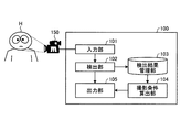
図1は、第1の実施形態にかかる監視装置100の構成を例示するブロック図である。図1に示すように、監視装置100は、入力部101と、検出部102と、検出結果管理部103と、撮影条件算出部104と、出力部105とを備える。カメラ150は、所定の領域に対して撮影を行う。例えば、カメラ150は、通行路の入退場対象エリアに対して撮影を行う監視カメラ等であり、撮影結果である動画像データを生成する。そして、入力部101は、カメラ150からの動画像データを入力処理する。入力部101は入力された動画像データを検出部102へ出力する。
(First embodiment)
FIG. 1 is a block diagram illustrating the configuration of a
カメラ150は、少なくとも1箇所、又は複数の地点に設置可能とする。また、カメラ150は、所定の領域に存在する人物の顔画像を入力するものであり、例えばITV(Industrial Television)カメラとする。カメラ150は、カメラのレンズを通して得られた光学的な情報をA/D変換器によりデジタル化して所定のフレームレートのフレーム画像データを生成し、監視装置100に対して出力する。また、カメラ150は、PTZ(パン・チルト・ズーム)カメラであり、水平方向、上下方向、回転、ズーム等の撮影条件が調整可能である。
The
図2は、カメラ150の撮影方向24を例示する概念図である。図2に示すように、カメラ150の撮影方向24は、カメラ150を設置するカメラ台座(図示しない)を調整することで、水平方向21(パン、ヨー方向)、上下方向22(チルト、ピッチ方向)、撮影方向24(ロール方向)において調整可能となっている。また、カメラ150は、レンズ位置を調整することで焦点調整が可能となっている。水平方向、上下方向、回転、ズーム等の撮影条件の調整については、ユーザが手動で行うものであってもよいし、アクチュエータなどで自動で行うものであってもよいものとする。
FIG. 2 is a conceptual diagram illustrating the
図1に戻り、検出部102は、入力された画像データ(入力画像)から人物の顔が表された顔領域を検出する。具体的には、検出部102は、入力画像内において、画像上の輝度情報を利用して顔の領域を示す座標を求める。ここでは文献(三田雄志ほか:「顔検出に適した共起に基づくJoint Haar−like特徴」電子情報通信学会論文誌(D),vol.J89−D,No8,pp1791−1801(2006))の方法を利用することによって実現となるため、本手法を利用することを前提とする。顔の向きや大きさにより検出された結果を示す情報は任意の形状でかまわないが、本実施例では簡単にするために、顔領域を矩形情報で示すこととし、その角の座標を検出結果として利用することとする。その他に予め用意されたテンプレートを画像内で移動させながら相関値を求めることにより、最も高い相関値を与える位置を顔領域とする方法、固有空間法や部分空間法を利用した顔抽出法などでも実現は可能である。
Returning to FIG. 1, the
また、カメラ150で撮影された映像においては、カメラ150の前の人物の移動(移動の軌跡)によって、検出された同一人物の顔が複数のフレームにわたって連続して映っていることが想定される。したがって、検出部102は、検出された同一の顔を同一人物として対応付けできるように人物の顔の追跡処理を行う必要がある。この実現手段としてはオプティカルフローを使って検出した顔が次のフレームでどの位置にいるか対応付けする手法や、特許公報(特開2011−170711号公報)を利用することで実現可能であり、顔部位を特徴点として検出する場合(後述する)は同一人物として対応付けられた複数フレームの顔領域の画像の中から検索をするのに適切な少なくとも1枚の画像を選択する方法や、最大で検出されたフレーム数までの任意の枚数の画像を利用することが可能となる。
In addition, in the video shot by the
さらに、検出された顔領域の部分の中から、目、鼻などの顔部位の位置を顔の特徴点として検出する。具体的には文献(福井和広、山口修:「形状抽出とパタン照合の組合せによる顔特徴点抽出」, 電子情報通信学会論文誌(D),vol.J80−D−II,No.8,pp2170−2177(1997))などの方法で実現可能である。また上記目・鼻の検出の他に口領域の検出については、文献(湯浅 真由美、中島 朗子:「高精度顔特徴点検出に基づくデジタルメイクシステム」第10回画像センシングシンポジウム予稿集,pp219−224(2004))の技術を利用することで容易に実現が可能である。いずれの場合でも二次元配列状の画像として取り扱える情報を獲得し、その中から顔特徴の領域を検出することが可能である。また、これらの処理は1枚の画像の中から1つの顔特徴だけを抽出するには全画像に対してテンプレートとの相関値を求め最大となる位置とサイズを出力すればよいし、複数の顔特徴を抽出するには画像全体に対する相関値の局所最大値を求め、一枚の画像内での重なりを考慮して顔の候補位置を絞り込み、最後は連続して入力された過去の画像との関係性(時間的な推移)も考慮して最終的に複数の顔特徴を同時に見つけることも可能となる。 Further, the position of a face part such as an eye or nose is detected as a facial feature point from the detected face area. Specifically, literature (Kazuhiro Fukui, Osamu Yamaguchi: “Face feature point extraction by combination of shape extraction and pattern matching”, IEICE Transactions (D), vol. J80-D-II, No. 8, pp2170 -2177 (1997)). In addition to the above-mentioned eye / nose detection, the literature (Mayumi Yuasa, Akiko Nakajima: “Digital Make System Based on High-Precision Facial Feature Point Detection” 10th Image Sensing Symposium Proceedings, pp 219-224 This can be easily realized by using the technique of (2004)). In any case, it is possible to acquire information that can be handled as a two-dimensional array of images and to detect a facial feature region from the information. Also, in these processes, in order to extract only one facial feature from one image, a correlation value with the template is obtained for all images, and the maximum position and size may be output. To extract facial features, obtain the local maximum correlation value for the entire image, narrow down the candidate face positions in consideration of the overlap in one image, and finally the past images that were input continuously It is also possible to finally find a plurality of facial features at the same time in consideration of the relationship (time transition).
顔の向きの推定については特開2003−141551号公報(「顔向き計算方法及びその装置」 東芝・山田貢己;福井和広;牧淳人;中島朗子) に示されているように、顔の回転行列、顔の向き別に学習させた複数のクラス(部分空間)を利用して顔向きを推定することが可能である。 Regarding the estimation of the face orientation, as disclosed in Japanese Patent Application Laid-Open No. 2003-141551 (“Face Orientation Calculation Method and Device” Toshiba, K. Yamada; Kazuhiro Fukui; Hayato Maki; Ayako Nakajima) It is possible to estimate the face orientation using a plurality of classes (subspaces) learned according to the rotation matrix and face orientation.
検出結果管理部103は、検出部102が検出した顔領域にかかる情報(検出結果)を記憶する。具体的には、検出結果管理部103は、検出部102が検出した人物の顔ごとに、入力画像中の顔領域の座標、複数のフレーム画像にわたって検出された顔領域の軌跡(動線)、顔領域から検出した顔部位(目、鼻など)の位置情報、推定した顔の向きを記憶するデータベースである。
The detection
撮影条件算出部104は、検出結果管理部103に記憶された検出結果をもとに、人物の顔を確認しやすくするカメラ150の上下方向、水平方向、回転方向における撮影方向、及び画角(ズーム)の少なくとも一つの撮影条件を算出する。例えば、検出結果管理部103において検出部102が検出した人物について、1〜N人分の検出結果が得られているものとすると、この1〜N人分について、人物の顔を確認しやすくする撮影条件を算出する。具体的には、撮影条件算出部104は、1〜N人分について検出結果管理部103に記憶された検出結果に基づいた、人物の顔の確認しやすさを評価する評価関数による評価値を最大とする撮影条件を算出する。
The imaging
図3は、第1の実施形態にかかる監視装置100の動作の一例を示すフローチャートであり、より具体的には撮影条件算出部104による撮影条件の算出を例示するフローチャートである。図3に示すように、撮影条件算出部104は、処理が開始されると、検出結果管理部103に記憶された検出結果(顔の検出・追跡結果)を取得する(S1)。次いで、撮影条件算出部104は、検出結果の取得個数(取得した人物の人数)が予め設定された所定数(N)以上であるか否かを判定する(S2)。所定数以上でない場合(S2:NO)はS1へ処理を戻して待機する。
FIG. 3 is a flowchart illustrating an example of the operation of the
所定数以上の検出結果がある場合(S2:YES)、撮影条件算出部104は、カメラ150の水平方向(パン)の角度θのとりうる範囲、すなわち撮影条件における水平方向のパラメータの範囲を、検出結果管理部103に記憶されたN人分の動線から設定する(S3)。
When there are more than a predetermined number of detection results (S2: YES), the shooting
図4は、N人分の動線d1〜dNと撮影方向24の関係を例示する概念図であり、より具体的には、撮影方向24を上から俯瞰した概念図である。図4に示すように、N人分の移動の軌跡が動線d1〜dNとして与えられているものとする。S3において、撮影条件算出部104は、カメラ150の撮影方向24と、動線d1〜dNが可能なかぎり平行となるように、各動線を直線で近似した時の撮影方向(水平方向)のなす角度を昇順にθ1、θ2、…θNとした場合、次の式(1)のように水平方向の角度θを設定する。
FIG. 4 is a conceptual diagram illustrating the relationship between the flow lines d1 to dN for N persons and the shooting
![]()
![]()
次いで、撮影条件算出部104は、カメラ150の上下方向(チルト)の角度φのとりうる範囲、すなわち撮影条件における上下方向のパラメータの範囲を、検出結果管理部103に記憶されたN人分の動線から設定する(S4)。
Next, the imaging
図5は、N人分の動線d1〜dNと撮影方向24の関係を例示する概念図であり、より具体的には、撮影方向24を横から俯瞰した概念図である。図5に示すように、N人分の移動の軌跡が動線d1〜dNとして与えられているものとする。S4において、撮影条件算出部104は、各動線について顔向きの角度をフレーム画像に関して平均した値を昇順にφ1、φ2、…φNとした場合、次の式(2)のように上下方向の角度φを設定する。
FIG. 5 is a conceptual diagram illustrating the relationship between the flow lines d1 to dN for N persons and the shooting
![]()
![]()
次いで、撮影条件算出部104は、カメラ150の回転方向(ロール)の角度ψのとりうる範囲、すなわち撮影条件における回転方向のパラメータの範囲を、検出結果管理部103に記憶されたN人分の動線から設定する(S5)。
Next, the imaging
図6は、N人分の動線d1〜dNとカメラ150の撮影画像Gの回転を例示する概念図である。図6に示すように、N人分の移動の軌跡が動線d1〜dNとして与えられているものとする。S5において、撮影条件算出部104は、撮影画像G内の各動線と、撮影画像Gの水平方向の直線とがなす角度をそれぞれ昇順にψ1、ψ2、…ψNとした場合、次の式(3)のように回転方向の角度ψを設定する。
FIG. 6 is a conceptual diagram illustrating the flow lines d1 to dN for N persons and the rotation of the captured image G of the
![]()
![]()
次いで、撮影条件算出部104は、カメラ150のズーム(画角)の取りうる範囲、すなわち撮影条件における画角のパラメータの範囲を設定する(S6)。具体的には、メモリなどに予め設定された、カメラ150のレンズ位置を調整することで可能な範囲内で、ズームのパラメータをrとしてr1、r2…rkのようなk個の値を設定する。なお、上述したθ、φ、ψについても、メモリなどに予め設定された、カメラ台座の稼働範囲内を上限値、下限値とする。
Next, the shooting
次いで、パン、チルト、ロール、ズームのパラメータの範囲を設定した撮影条件について、上述した評価関数による評価値を最大とするパン、チルト、ロール、ズームの値を計算する。この評価関数による評価値の算出は、顔のサイズが大きい、顔の向きがカメラ150に対して正面、撮影範囲が広いなどの、顔を目視した監視には理想的であるが、両立が難しい基準を考慮して、次の式(4)により行う。
Next, the pan, tilt, roll, and zoom values that maximize the evaluation value based on the above-described evaluation function are calculated for the shooting conditions in which the ranges of the pan, tilt, roll, and zoom parameters are set. Calculation of the evaluation value using this evaluation function is ideal for monitoring the face visually, such as when the face size is large, the face direction is front of the
式(4)において、A、B、C、D(>=0)は、調整するパラメータであるθ、φ、ψ、rのいずれを重視するかを定めるパラメータである。このA、B、C、Dについては、一つのパラメータを有効(>=0)にして、一つ以上の撮影条件を評価できるようにする。g(r)は、例えば、各動線の各フレーム画像に含まれる顔のうち、ズームすることによって画角(撮像領域)に含まれなくなる個数Xから、各動線の各フレーム画像に含まれる顔のサイズがあらかじめ定めた範囲S画素以上、S画素以下となるものの数Yを引いたものとする。なお、顔サイズと画角の広さのトレードオフを表現できるものであれば他の関数でもよい。この評価値の最大化はたとえばrの値を固定すると線形計画法で計算できるので、各rの値について、線形計画問題を解くことで実現できる。また、顔サイズや画角などはカメラと被写体の3次元情報が得られれば計算できる。評価関数(目的関数)は上記のような顔向きや顔サイズを所望の条件で撮影するように調整するものであればよく、この関数を最大化あるいは最小化(本実施形態では評価値を高くすることが人物の顔を確認しやすいことを示すので最大化)する手段が与えられていればよい。 In Expression (4), A, B, C, and D (> = 0) are parameters that determine which of θ, φ, ψ, and r, which are parameters to be adjusted, are important. For A, B, C, and D, one parameter is enabled (> = 0) so that one or more photographing conditions can be evaluated. g (r) is included in each frame image of each flow line, for example, from the number X of faces included in each frame image of each flow line that are not included in the angle of view (imaging area) by zooming. It is assumed that the number Y of faces whose face size is a predetermined range of S pixels or more and S pixels or less is subtracted. Other functions may be used as long as they can express the trade-off between the face size and the angle of view. Since the evaluation value can be maximized by, for example, linear programming when the value of r is fixed, it can be realized by solving a linear programming problem for each value of r. Also, the face size and angle of view can be calculated if three-dimensional information about the camera and subject is obtained. The evaluation function (objective function) may be any function as long as the face orientation and the face size are adjusted so as to be photographed under a desired condition. This function is maximized or minimized (in this embodiment, the evaluation value is increased). This means that it is easy to confirm the person's face.
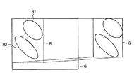
図7は、撮影画像Gのズームを例示する概念図である。図7に示すように、検出結果による顔の頻度を調べて得られた、顔が頻出する領域R1、R2を撮影領域Rとして限定し、拡大して撮影するようにしてよい。また、上述した処理を行うことで、図6のような動線の傾きを補正するように回転する角度を計算することもできる。また、検出結果が一定期間にわたって出力されない場合は、適切な撮影条件が算出できないものとして、出力部105より警告を出力してもよい。
FIG. 7 is a conceptual diagram illustrating zooming of the captured image G. As shown in FIG. 7, the regions R1 and R2 where the face appears frequently obtained by examining the frequency of the face based on the detection result may be limited to the imaging region R and may be enlarged and photographed. Further, by performing the above-described processing, the rotation angle can be calculated so as to correct the inclination of the flow line as shown in FIG. Further, when the detection result is not output over a certain period, a warning may be output from the
出力部105は、表示装置などであり、撮影条件算出部104により算出された撮影条件を表示出力する。また、出力部105は、入力部101の入力画像の表示や、その入力画像に検出部102で検出された顔領域を重畳した表示なども行う。ユーザは、出力部105より出力された撮影条件を確認することで、カメラ150で撮影した人物の顔を確認しやすくするように、カメラ150の水平方向、上下方向、回転方向、ズーム(画角)等を容易に調整できる。
The
(変形例)
次に、監視装置100の変形例について説明する。図8は、変形例にかかる監視装置100aの構成を示すブロック図である。なお、監視装置100aにおいて、監視装置100と同じ構成については同一の符号を付してその説明を省略する。
(Modification)
Next, a modified example of the
図8に示すように、監視装置100aは、入力部101と、検出部102と、検出結果管理部103と、撮影条件算出部104と、出力部105と、撮影条件制御部106と、特徴抽出部107と、人物情報管理部108と、認識部109とを備える。
As shown in FIG. 8, the
撮影条件制御部106は、撮影条件算出部104によって算出したパラメータにしたがって、カメラ150のアクチュエータ(図示しない)に駆動信号を出力することで、カメラ150の水平方向21の角度、上下方向22の角度、ロール方向23の角度、画面の解像度、画面のズームを制御する。撮影条件制御部106により、カメラ150は、カメラ150で撮影した人物の顔を確認しやすくする撮影条件に、ユーザが手動で変更することなく、自動的に変更することができる。
The shooting
特徴抽出部107は、検出部102により検出された顔の領域の情報から個人を識別するための特徴情報(以降「顔特徴」とはこの個人を識別するための特徴情報を示すこととする)を数値として出力する。特徴抽出に利用する画像は入力部101によって得られた入力画像を利用する。特徴抽出部107は、入力部101による入力画像と、検出部102によって検出された人物領域を対応付けて、特徴抽出に必要な画像領域、本実施例では顔領域の検出をしているので顔の領域を切り出し、その濃淡情報を特徴量として用いる。複数フレームの画像を利用する場合にそなえて画像補正手段で複数フレームの出力をするようにしてもよい。
The
ここでは、mピクセル×nピクセルの領域の濃淡値をそのまま情報として用い、m×n次元の情報を特徴ベクトルとして用いる。これらは単純類似度法という手法によりベクトルとベクトルの長さをそれぞれ1とするように正規化を行い、内積を計算することで特徴ベクトル間の類似性を示す類似度が求められる。詳しくは文献(エルッキ・オヤ著、小川英光、佐藤誠訳、「パタン認識と部分空間法」、産業図書、1986年)にあるように部分空間法を利用することで実現できる。文献(東芝(小坂谷達夫):「画像認識装置、方法およびプログラム」特開2007−4767号公報)にあるように1枚の人物画像情報に対してモデルを利用して顔の向きや状態を意図的に変動させた画像を作成することによってより精度の高まる手法を適用してもよい。1枚の画像から顔の特徴を求める場合にはここまでの処理で顔特徴抽出は完了する。一方で同一人物に対して連続した複数の画像を利用した動画像による計算をすることでより精度の高い認識処理が行うこともできる。具体的には文献(福井和広、山口修、前田賢一:「動画像を用いた顔認識システム」電子情報通信学会研究報告PRMU,vol97,No.113,pp17−24(1997)、前田賢一、渡辺貞一:「局所的構造を導入したパタン・マッチング法」, 電子情報通信学会論文誌(D),vol.J68−D,No.3,pp345−352(1985))にある相互部分空間法を用いる方法で説明する。入力手段から連続して得られた画像から特徴抽出手段と同様にm×nピクセルの画像を切り出しこれらのデータを特徴ベクトルの相関行列を求め、K−L展開による正規直交ベクトルを求めることにより、連続した画像から得られる顔の特徴を示す部分空間を計算する。部分空間の計算法は、特徴ベクトルの相関行列(または共分散行列)を求め、そのK−L展開による正規直交ベクトル(固有ベクトル)を求めることにより、部分空間を計算する。部分空間は、固有値に対応する固有ベクトルを、固有値の大きな順にk個選び、その固有ベクトル集合を用いて表現する。本実施例では、相関行列Cdを特徴ベクトルから求め、相関行列Cd =Φd Λd Φd T と対角化して、固有ベクトルの行列Φを求める。この情報が現在認識対象としている人物の顔の特徴を示す部分空間となる。このような方法で出力された部分空間のような特徴情報を入力された画像で検出された顔に対する個人の特徴情報とする。 Here, the gray value of an area of m pixels × n pixels is used as information as it is, and m × n-dimensional information is used as a feature vector. These are normalized so that the vector and the length of each vector are set to 1 by a method called a simple similarity method, and a similarity indicating the similarity between feature vectors is obtained by calculating an inner product. For details, this can be realized by using the subspace method as described in the literature (written by Elkki Oya, Hidemitsu Ogawa, Makoto Sato, “Pattern Recognition and Subspace Method”, Sangyo Tosho, 1986). Document (Toshiba (Tatsuo Kosakaya): “Image recognition apparatus, method and program”, Japanese Patent Laid-Open No. 2007-4767) discloses the orientation and state of a face using a model for one piece of human image information. You may apply the method of improving a precision by producing the image changed intentionally. When the facial features are obtained from one image, the facial feature extraction is completed by the processing so far. On the other hand, recognition processing with higher accuracy can be performed by calculating with a moving image using a plurality of continuous images for the same person. Specifically, the literature (Kazuhiro Fukui, Osamu Yamaguchi, Kenichi Maeda: “Face Recognition System Using Moving Images” IEICE Research Report PRMU, vol 97, No. 113, pp 17-24 (1997), Kenichi Maeda, Watanabe Sadaichi: Use the mutual subspace method described in "Pattern matching method with local structure", IEICE Transactions (D), vol. J68-D, No. 3, pp 345-352 (1985)). How to explain. Similar to the feature extraction unit, an image of m × n pixels is cut out from images continuously obtained from the input unit, a correlation matrix of the feature vectors is obtained from these data, and an orthonormal vector by KL expansion is obtained. A subspace indicating facial features obtained from successive images is calculated. The subspace calculation method calculates a subspace by obtaining a correlation matrix (or covariance matrix) of feature vectors and obtaining an orthonormal vector (eigenvector) by KL expansion. In the subspace, k eigenvectors corresponding to eigenvalues are selected in descending order of eigenvalues, and expressed using the eigenvector set. In the present embodiment, the correlation matrix Cd is obtained from the feature vector, and diagonalized with the correlation matrix Cd = ΦdΛdΦdT to obtain the eigenvector matrix Φ. This information becomes a partial space indicating the characteristics of the face of the person currently recognized. The feature information such as the partial space output by such a method is used as the individual feature information for the face detected in the input image.
人物情報管理部108は、後述の認識部109で検索するときに利用する対象となるデータベースであり、検索対象となる個人ごとに特徴抽出部107で抽出された顔特徴情報、および性別や年齢、身長など属性判別手段で判別可能な属性情報のように人物に関する付随した情報を同一の人物ごとに対応付けて管理する。顔特徴情報および属性情報として実際に管理する内容は特徴抽出部107で出力されたデータそのものでよく、m×nの特徴ベクトルや、部分空間やKL展開を行う直前の相関行列でも構わない。さらに、特徴抽出部107で出力される特徴情報を入力手段より登録時に入力された人物画像とともに管理することで個人の検索や検索の表示に利用することができる。
The person
認識部109は、特徴抽出部107で得られた入力画像の顔特徴情報と、対応する人物情報管理部108に記憶された顔特徴情報との類似性を示す計算を行ってより類似性の高いものから順番に結果を返す処理を行う。また上述したように所定の属性情報に絞り込んで人物情報管理部108を一部分だけ検索するといったことも可能である。
The recognizing
この際に検索処理の結果としては類似性の高いものから順番に人物情報管理部108内で個人を識別するために管理されている人物ID,計算結果である類似性を示す指標を返す。それに加えて個人ごとに管理されている情報を一緒に返すようにしてもかまわないが、基本的に識別IDにより対応付けが可能であるので検索処理自体では付属情報をやりとりすることはなくても実現が可能となる。類似性を示す指標としては顔特徴情報として管理されている部分空間同士の類似度とする。計算方法は、部分空間法や複合類似度法などの方法を用いてよい。この方法では、予め蓄えられた登録情報の中の認識データも、入力されるデータも複数の画像から計算される部分空間として表現され、2つの部分空間のなす「角度」を類似度として定義する。ここで入力される部分空間を入力手段分空間という。入力データ列に対して同様に相関行列Cinを求め、Cin=ΦinΛinΦinT と対角化し、固有ベクトルΦinを求める。二つのΦin,Φd で表される部分空間の部分空間間類似度(0.0〜1.0)を求め、これを認識するための類似度とする。具体的な計算方法については特徴抽出部107の説明で紹介した文献(エルッキ・オヤ)で実現が可能である。また、あらかじめ同一人物と分かる複数の人物画像をまとめて部分空間への射影によって本人であるかどうかを識別することで精度を向上させることも可能であり、文献(福井・小坂谷)でも同様の処理を行うこともできる。高速に検索するにはTREE構造を利用した検索方法なども利用可能である。
At this time, as a result of the search process, a person ID managed in order to identify an individual in the person
出力部105では、認識部109で得られた結果、および入力された画像を画面に表示する。認識部109によって検索された結果のうち指定した条件にあうものをリアルタイムに表示するリアルタイム顔検索結果表示と、認識部109によって検索された結果を検索履歴として保存しておき、後から条件を指定することで該当する検索履歴だけ表示するオフラインの顔検索結果表示のいずれか一方、または両方を組み込むことが可能である。
The
(第2の実施形態)
図9は、第2の実施形態にかかる監視装置100bの構成を示すブロック図である。なお、監視装置100bにおいて、監視装置100と同じ構成については同一の符号を付してその説明を省略する。
(Second Embodiment)
FIG. 9 is a block diagram illustrating a configuration of a
図9に示すように、監視装置100bは、入力部101と、検出部102と、出力部105と、撮影条件記憶部110と、撮影条件診断部111とを備える。
As illustrated in FIG. 9, the
撮影条件記憶部110は、カメラ150で撮影した人物の顔を確認しやすくするカメラの撮影条件として、あらかじめ定めておいた顔サイズ、顔の向き、視野角などの推奨値、背景の画像、又はカメラ150のパン、ヨー方向(水平方向)、チルト、ピッチ方向(上下方向)、ロール方向(回転方向)、及びズームの拡大率などの情報を記憶する。なお、第1の実施形態のようにカメラ150の前を移動する人物の追跡履歴から定めた値を記録してもよいし、ユーザが事前に画面を目視で確認しながら、設定した値を記録してもよい。
The photographing
撮影条件診断部111は、検出部102の検出結果に基づいた、人物の顔に対するカメラ150の上下方向、水平方向、回転方向における撮影方向、及び画角の少なくとも一つの撮影条件が、撮影条件記憶部110に記憶された撮影条件に整合するか否かを判定する。
Based on the detection result of the
図10は、第2の実施形態にかかる監視装置100bの動作の一例を示すフローチャートであり、より具体的には撮影条件診断部111による撮影条件の判定を例示するフローチャートである。図10に示すように、撮影条件診断部111は、S11〜S17の処理が予め設定された反復数の上限回実施されたか否かを判定する(S10)。ここで、反復数の上限回実施されていない場合(S10:NO)、撮影条件診断部111は、S11〜S17の処理を継続する。反復数の上限回実施された場合(S10:YES)、撮影条件診断部111は、S18へ処理を進める。
FIG. 10 is a flowchart illustrating an example of the operation of the
S11において、撮影条件診断部111は、検出部102の検出結果(顔の検出・追跡結果)を取得する。次いで、撮影条件診断部111は、検出結果の人数が0人であるか否かを判定する(S12)。0人である場合(S12:YES)、撮影条件診断部111は、入力部101の入力画像を背景画像として記憶し(S13)、処理の反復数をインクリメントする(S17)。0人でない場合(S12:NO)、撮影条件診断部111は、検出部102の検出結果である顔サイズ、顔の向き、動線を記憶し(S14〜16)、処理の反復数をインクリメントする(S17)。
In S <b> 11, the imaging
S18において、撮影条件診断部111は、S12〜S17の処理で記憶されたデータと、撮影条件記憶部110に記憶された撮影条件とをもとに、撮影条件の整合性の評価値を計算し(S18)、その計算結果(整合するか否かの判定結果)を出力部105へ出力する(S19)。出力部105では、カメラ150の撮影条件が撮影条件記憶部110に予め記憶された撮影条件と整合するか否かを表示出力する。
In S18, the imaging
具体的には、撮影条件診断部111は、入力画像から人物が検出されていない場合は背景画像を記憶し、S18において、記憶しておいた背景画像と差分を計算し、画素または隣接する画素をまとめたブロックごとに背景である事後確率を得ることができる(中井 宏章、特開平09−81714号公報)。また、顔検出結果の顔のサイズを記録しておき、顔のサイズが撮影条件記憶部110で指定した画素以上、S画素以下の範囲に含まれない顔の数Xにもとづいて整合性を判断することもできる。また、顔向きの水平方向の角度、垂直方向の角度、画面内回転の角度を記録しておき、撮影条件記憶部110で指定した顔向きの範囲に含まれない顔の数Yにもとづいて整合性を判断することもできる。顔向きは前述した手法で計算することができる。また、検出部102で得られた動線の情報から動線と画像の水平方向の直線がなす角度が撮影条件記憶部110で指定した角度の範囲に含まれない人物の数Zにもとづいて整合性を判断することもできる。また、検出部102で得られる人物の追跡で計数した人数をNとして、Nが撮影条件記憶部110で指定した人数よりも少ない場合は不適切な画角であると判断することもできる。
Specifically, the imaging
また、背景画像との差分や色ヒストグラムの比較により、登録された条件と異なることを判定することもできる。エッジ、コーナーなどの局所特徴量や局所領域の輝度分布にもとづいた特徴量を用いることもできる。この判定には画面全体で特徴量をもとめてそれぞれの座標値を個別に覚えてもよいし、画面全体を小領域に分割してそれぞれのブロック単位で特徴情報を計算して比較してよい。 Further, it is possible to determine that the registered condition is different from the difference between the background image and the comparison of the color histogram. It is also possible to use feature quantities based on local feature quantities such as edges and corners and the luminance distribution of local areas. For this determination, the feature values may be obtained for the entire screen and the respective coordinate values may be memorized individually, or the entire screen may be divided into small areas and feature information may be calculated and compared for each block.
図11は、第1、第2の実施形態にかかる監視装置100、100a、100bのハードウエア構成を示したブロック図である。図11に示すように、監視装置100、100a、100bは、CPU1101と、ROM(Read Only Memory)1102と、RAM(Random Access Memory)1103と、通信I/F1104と、HDD1105と、表示装置1106と、キーボードやマウスなどの入力デバイス1107と、これらを接続するバス1108と、を備えており、通常のコンピュータを利用したハードウェア構成となっている。
FIG. 11 is a block diagram illustrating a hardware configuration of the
本実施形態の監視装置100、100a、100bで実行されるプログラムは、インストール可能な形式又は実行可能な形式のファイルでCD−ROM、フレキシブルディスク(FD)、CD−R、DVD(Digital Versatile Disk)等のコンピュータで読み取り可能な記録媒体に記録されて提供される。
The programs executed by the monitoring
また、本実施形態の監視装置100、100a、100bで実行されるプログラムを、インターネット等のネットワークに接続されたコンピュータ上に格納し、ネットワーク経由でダウンロードさせることにより提供するように構成しても良い。また、本実施形態の監視装置100、100a、100bで実行されるプログラムをインターネット等のネットワーク経由で提供または配布するように構成しても良い。また、本実施形態のプログラムを、ROM等に予め組み込んで提供するように構成してもよい。
The program executed by the
本実施形態の監視装置100、100a、100bで実行されるプログラムは、上述した各構成を含むモジュール構成となっており、実際のハードウェアとしてはCPU1101が上記記憶媒体からプログラムを読み出して実行することにより上記各構成がRAM1103上にロードされ、上記各構成がRAM1103上に生成される。
The program executed by the
本発明のいくつかの実施形態を説明したが、これらの実施形態は、例として提示したものであり、発明の範囲を限定することは意図していない。これら新規な実施形態は、その他の様々な形態で実施されることが可能であり、発明の要旨を逸脱しない範囲で、種々の省略、置き換え、変更を行うことができる。これら実施形態やその変形は、発明の範囲や要旨に含まれるとともに、特許請求の範囲に記載された発明とその均等の範囲に含まれる。 Although several embodiments of the present invention have been described, these embodiments are presented by way of example and are not intended to limit the scope of the invention. These novel embodiments can be implemented in various other forms, and various omissions, replacements, and changes can be made without departing from the scope of the invention. These embodiments and modifications thereof are included in the scope and gist of the invention, and are included in the invention described in the claims and the equivalents thereof.
100、100a、100b…監視装置、21…水平方向、22…上下方向、23…ロール方向、24…撮影方向、101…入力部、102…検出部、103…検出結果管理部、104…撮影条件算出部、105…出力部、106…撮影条件制御部、107…特徴抽出部、109…認識部、108…人物情報管理部、110…撮影条件記憶部、111…撮影条件診断部、150…カメラ、1101…CPU、1102…ROM、1103…RAM、1104…通信I/F、1105…HDD、1106…表示装置、1107…入力デバイス、1108…バス、d1、d2、dN…動線、G…撮影画像、R…撮影領域、R1、R2…領域
DESCRIPTION OF
Claims (13)
前記入力された画像データから人物の顔が表された顔領域を検出する顔検出手段と、
前記顔検出手段の検出結果を記憶する検出結果記憶手段と、
前記記憶された検出結果をもとに、式(1)に従って、前記カメラの上下方向の角度φ、水平方向の角度θ、回転方向における撮影方向の角度ψ、及び画角rをパラメータとし、前記記憶された顔領域に基づいた前記人物の顔の確認しやすさを評価する評価関数による評価値を最大とする少なくとも一つの撮影条件を算出する算出手段と、
前記算出された撮影条件を出力する出力手段と、
を備える監視装置。
Face detection means for detecting a face area representing a human face from the input image data;
Detection result storage means for storing the detection result of the face detection means;
Based on the stored detection result, according to the equation (1), the vertical angle φ 1 of the camera, the horizontal angle θ 2 , the angle ψ of the shooting direction in the rotation direction, and the angle of view r are used as parameters. Calculating means for calculating at least one photographing condition that maximizes an evaluation value by an evaluation function for evaluating ease of confirmation of the face of the person based on a stored face area ;
Output means for outputting the calculated photographing condition;
A monitoring device comprising:
前記算出手段は、前記記憶された顔領域の大きさをもとに、当該顔領域の大きさを所定の大きさとする撮影条件を算出する、
請求項1に記載の監視装置。 The face detecting means detects a size of the face region;
The calculating means calculates a shooting condition based on the size of the stored face area, with the face area having a predetermined size;
The monitoring apparatus according to claim 1 .
前記算出手段は、前記記憶された顔の向きをもとに、当該顔の向きを所定の方向とする撮影条件を算出する、
請求項1に記載の監視装置。 The face detecting means detects a face direction based on a face part included in the face region;
The calculation means calculates shooting conditions based on the stored face orientation, with the face orientation being a predetermined direction.
The monitoring apparatus according to claim 1 .
前記算出手段は、前記複数のフレーム画像にわたって記憶された顔領域をもとにした、前記人物の移動の軌跡に対し、所定の方向から撮影する撮影条件を算出する、
請求項1に記載の監視装置。 The detection result storage means stores the face area detected by the face detection means over a plurality of frame images,
The calculation means calculates shooting conditions for shooting from a predetermined direction with respect to a trajectory of movement of the person based on the face area stored over the plurality of frame images.
The monitoring apparatus according to claim 1 .
請求項1乃至4のいずれか一項に記載の監視装置。 Control means for controlling the shooting direction and angle of view of the camera based on the calculated shooting conditions,
The monitoring apparatus as described in any one of Claims 1 thru | or 4 .
前記入力された画像データから人物の顔が表された顔領域の検出を、予め設定された反復数、実施するまで継続する顔検出手段と、
前記人物の顔を確認しやすくする前記カメラの撮影条件を記憶する撮影条件記憶手段と、
前記顔検出手段の前記反復数分の検出結果に基づいた、前記人物の顔に対する前記カメラの上下方向、水平方向、回転方向における撮影方向、及び画角の少なくとも一つの撮影条件が、前記記憶された撮影条件に整合するか否かを判定する判定手段と、
前記判定手段の判定結果を出力する出力手段と、
を備える監視装置。 Image input means for inputting image data captured by the camera;
Detects a face of a person from the input image data is represented the face area, a preset number of iterations, a face detection unit which continues until the implementation,
Shooting condition storage means for storing shooting conditions of the camera for facilitating confirmation of the person's face;
Based on the detection results for the number of repetitions of the face detection means, at least one shooting condition of the camera's face in the vertical direction, horizontal direction, shooting direction in the rotation direction, and angle of view is stored. Determining means for determining whether or not it matches the shooting conditions;
Output means for outputting a determination result of the determination means;
A monitoring device comprising:
前記判定手段は、前記検出結果に基づいた顔サイズが前記記憶された顔サイズと整合するか否かを判定する、
請求項6に記載の監視装置。 The photographing condition storage means stores the face size of the person when the person is photographed with the camera as the photographing condition,
The determination unit determines whether or not a face size based on the detection result matches the stored face size;
The monitoring device according to claim 6 .
前記判定手段は、前記検出結果に基づいた顔の向きが前記記憶された顔の向きと整合するか否かを判定する、
請求項6に記載の監視装置。 The photographing condition storage means stores the face direction of the person when the person is photographed by the camera as the photographing condition,
The determination means determines whether or not a face orientation based on the detection result matches the stored face orientation;
The monitoring device according to claim 6 .
前記判定手段は、複数のフレーム画像にわたって前記顔検出手段により検出された顔領域をもとにした、前記人物の移動の軌跡が前記記憶された移動の軌跡と整合するか否かを判定する、
請求項6に記載の監視装置。 The shooting condition storage means stores, as the shooting condition, the shooting direction of the camera with respect to a trajectory of movement of the person when the person moves in front of the camera,
The determination unit determines whether or not the movement trajectory of the person matches the stored movement trajectory based on the face area detected by the face detection unit over a plurality of frame images;
The monitoring device according to claim 6 .
前記判定手段は、前記検出結果に基づいた前記顔領域以外の領域の画素値が前記記憶された画素値と整合するか否かを判定する、
請求項6に記載の監視装置。 The photographing condition storage means stores, as the photographing condition, a pixel value in the background of the person when the person is photographed by the camera.
The determination means determines whether or not a pixel value of an area other than the face area based on the detection result matches the stored pixel value.
The monitoring device according to claim 6 .
請求項6乃至10のいずれか一項に記載の監視装置。 The determination unit determines whether the shooting condition based on the detection result of the face detection unit matches the stored shooting condition for all or a part of the image in the image data captured by the camera. To determine,
The monitoring device according to any one of claims 6 to 10 .
画像入力手段が、カメラが撮像した画像データを入力するステップと、
顔検出手段が、前記入力された画像データから人物の顔が表された顔領域を検出するステップと、
検出結果記憶手段が、前記顔領域の検出結果を記憶するステップと、
算出手段が、前記記憶された検出結果をもとに、式(1)に従って、前記カメラの上下方向の角度φ、水平方向の角度θ、回転方向における撮影方向の角度ψ、及び画角rをパラメータとして、前記記憶された顔領域に基づいた前記人物の顔の確認しやすさを評価する評価関数による評価値を最大とする少なくとも一つの撮影条件を算出するステップと、
出力手段が、前記算出された撮影条件を出力するステップと、
を含む方法。
An image input means for inputting image data captured by the camera;
A step of detecting a face area in which a human face is represented from the input image data;
A detection result storing means for storing the detection result of the face area;
Based on the stored detection result, the calculating means calculates the vertical angle φ 1 of the camera, the horizontal angle θ 2 , the shooting direction angle φ 2 in the rotation direction, and the angle of view r according to the equation (1). Calculating at least one imaging condition that maximizes an evaluation value by an evaluation function for evaluating ease of confirming the face of the person based on the stored face area as a parameter ;
An output means for outputting the calculated photographing condition;
Including methods.
前記監視装置は、人物の顔を確認しやすくするカメラの撮影条件を記憶する撮影条件記憶手段を備え、
画像入力手段が、カメラが撮像した画像データを入力するステップと、
顔検出手段が、前記入力された画像データから人物の顔が表された顔領域の検出を、予め設定された反復数、実施するまで継続するステップと、
判定手段が、前記反復数分の前記顔領域の検出結果に基づいた、前記人物の顔に対する前記カメラの上下方向、水平方向、回転方向における撮影方向、及び画角の少なくとも一つの撮影条件が、前記記憶された撮影条件に整合するか否かを判定するステップと、
出力手段が、判定された判定結果を出力するステップと、
を含む方法。 A method performed by a monitoring device, comprising:
The monitoring device includes a shooting condition storage unit that stores shooting conditions of a camera that makes it easy to check a person's face,
An image input means for inputting image data captured by the camera;
A step of the face detecting means continues to detect the face of a person from the input image data is represented the face area, a preset number of iterations, until the implementation,
Based on the detection result of the face area for the number of repetitions , the determination unit has at least one shooting condition of the shooting direction in the vertical direction, horizontal direction, rotation direction, and angle of view of the person's face, Determining whether or not it matches the stored shooting conditions;
An output means for outputting the determined determination result;
Including methods.
Priority Applications (1)
| Application Number | Priority Date | Filing Date | Title |
|---|---|---|---|
| JP2012206773A JP5971712B2 (en) | 2012-09-20 | 2012-09-20 | Monitoring device and method |
Applications Claiming Priority (1)
| Application Number | Priority Date | Filing Date | Title |
|---|---|---|---|
| JP2012206773A JP5971712B2 (en) | 2012-09-20 | 2012-09-20 | Monitoring device and method |
Publications (2)
| Publication Number | Publication Date |
|---|---|
| JP2014064083A JP2014064083A (en) | 2014-04-10 |
| JP5971712B2 true JP5971712B2 (en) | 2016-08-17 |
Family
ID=50618963
Family Applications (1)
| Application Number | Title | Priority Date | Filing Date |
|---|---|---|---|
| JP2012206773A Expired - Fee Related JP5971712B2 (en) | 2012-09-20 | 2012-09-20 | Monitoring device and method |
Country Status (1)
| Country | Link |
|---|---|
| JP (1) | JP5971712B2 (en) |
Families Citing this family (6)
| Publication number | Priority date | Publication date | Assignee | Title |
|---|---|---|---|---|
| JP6675607B2 (en) * | 2015-05-28 | 2020-04-01 | 国立大学法人東京工業大学 | Image processing apparatus, image processing system, and image processing program |
| JP6670496B2 (en) * | 2015-11-24 | 2020-03-25 | 株式会社ブイシンク | Image processing device |
| JP6739200B2 (en) | 2016-03-24 | 2020-08-12 | キヤノン株式会社 | Video processing device, video processing system and control method |
| JP2017208616A (en) | 2016-05-16 | 2017-11-24 | キヤノン株式会社 | Image processing apparatus, image processing method, and program |
| JP6721076B1 (en) * | 2019-03-25 | 2020-07-08 | 日本電気株式会社 | Information processing device, camera control method, program, camera device, and image processing system |
| JP7291013B2 (en) | 2019-06-28 | 2023-06-14 | セコム株式会社 | Camera placement evaluation device, camera placement evaluation method, and computer program |
Family Cites Families (5)
| Publication number | Priority date | Publication date | Assignee | Title |
|---|---|---|---|---|
| JP4577113B2 (en) * | 2005-06-22 | 2010-11-10 | オムロン株式会社 | Object determining device, imaging device, and monitoring device |
| JP2010239532A (en) * | 2009-03-31 | 2010-10-21 | Casio Computer Co Ltd | Image capturing apparatus and method |
| JP4985742B2 (en) * | 2009-10-19 | 2012-07-25 | 日本電気株式会社 | Imaging system, method and program |
| JP2011135247A (en) * | 2009-12-24 | 2011-07-07 | Nikon Corp | Imaging apparatus |
| JP2011188065A (en) * | 2010-03-05 | 2011-09-22 | Sony Corp | Imaging controller, method of detecting subject, and program |
-
2012
- 2012-09-20 JP JP2012206773A patent/JP5971712B2/en not_active Expired - Fee Related
Also Published As
| Publication number | Publication date |
|---|---|
| JP2014064083A (en) | 2014-04-10 |
Similar Documents
| Publication | Publication Date | Title |
|---|---|---|
| US9098760B2 (en) | Face recognizing apparatus and face recognizing method | |
| KR102596897B1 (en) | Method of motion vector and feature vector based fake face detection and apparatus for the same | |
| JP5766564B2 (en) | Face authentication apparatus and face authentication method | |
| KR101490016B1 (en) | Person image processing apparatus and person image processing method | |
| JP6013241B2 (en) | Person recognition apparatus and method | |
| JP5642410B2 (en) | Face recognition device and face recognition method | |
| EP2357589B1 (en) | Image recognition apparatus and method | |
| US8836777B2 (en) | Automatic detection of vertical gaze using an embedded imaging device | |
| US8819015B2 (en) | Object identification apparatus and method for identifying object | |
| WO2019056988A1 (en) | Face recognition method and apparatus, and computer device | |
| JP5971712B2 (en) | Monitoring device and method | |
| JP5992276B2 (en) | Person recognition apparatus and method | |
| CN108985210A (en) | A kind of Eye-controlling focus method and system based on human eye geometrical characteristic | |
| JP6822482B2 (en) | Line-of-sight estimation device, line-of-sight estimation method, and program recording medium | |
| JP2007074033A (en) | Imaging apparatus and control method thereof, computer program, and storage medium | |
| KR20170015639A (en) | Personal Identification System And Method By Face Recognition In Digital Image | |
| CN107862240A (en) | A kind of face tracking methods of multi-cam collaboration | |
| WO2020195732A1 (en) | Image processing device, image processing method, and recording medium in which program is stored | |
| JP5787686B2 (en) | Face recognition device and face recognition method | |
| JP2016200969A (en) | Image processing apparatus, image processing method, and program | |
| CN114360039A (en) | Intelligent eyelid detection method and system | |
| JP4708835B2 (en) | Face detection device, face detection method, and face detection program | |
| JP5791361B2 (en) | PATTERN IDENTIFICATION DEVICE, PATTERN IDENTIFICATION METHOD, AND PROGRAM | |
| KR20180015792A (en) | System and method for fear mentality analysis | |
| KR101031369B1 (en) | Apparatus for identifying face from image and method thereof |
Legal Events
| Date | Code | Title | Description |
|---|---|---|---|
| A621 | Written request for application examination |
Free format text: JAPANESE INTERMEDIATE CODE: A621 Effective date: 20150306 |
|
| RD01 | Notification of change of attorney |
Free format text: JAPANESE INTERMEDIATE CODE: A7421 Effective date: 20151102 |
|
| A977 | Report on retrieval |
Free format text: JAPANESE INTERMEDIATE CODE: A971007 Effective date: 20151224 |
|
| A131 | Notification of reasons for refusal |
Free format text: JAPANESE INTERMEDIATE CODE: A131 Effective date: 20160119 |
|
| A521 | Request for written amendment filed |
Free format text: JAPANESE INTERMEDIATE CODE: A523 Effective date: 20160322 |
|
| TRDD | Decision of grant or rejection written | ||
| A01 | Written decision to grant a patent or to grant a registration (utility model) |
Free format text: JAPANESE INTERMEDIATE CODE: A01 Effective date: 20160607 |
|
| A61 | First payment of annual fees (during grant procedure) |
Free format text: JAPANESE INTERMEDIATE CODE: A61 Effective date: 20160706 |
|
| R151 | Written notification of patent or utility model registration |
Ref document number: 5971712 Country of ref document: JP Free format text: JAPANESE INTERMEDIATE CODE: R151 |
|
| LAPS | Cancellation because of no payment of annual fees |