JP5970848B2 - Screen device for replenishing device, replenishing unit, developing unit, image forming apparatus, and toner replenishing method - Google Patents
Screen device for replenishing device, replenishing unit, developing unit, image forming apparatus, and toner replenishing method Download PDFInfo
- Publication number
- JP5970848B2 JP5970848B2 JP2012033045A JP2012033045A JP5970848B2 JP 5970848 B2 JP5970848 B2 JP 5970848B2 JP 2012033045 A JP2012033045 A JP 2012033045A JP 2012033045 A JP2012033045 A JP 2012033045A JP 5970848 B2 JP5970848 B2 JP 5970848B2
- Authority
- JP
- Japan
- Prior art keywords
- toner
- blade
- filter
- replenishing
- sieve
- Prior art date
- Legal status (The legal status is an assumption and is not a legal conclusion. Google has not performed a legal analysis and makes no representation as to the accuracy of the status listed.)
- Active
Links
Images


Classifications
-
- G—PHYSICS
- G03—PHOTOGRAPHY; CINEMATOGRAPHY; ANALOGOUS TECHNIQUES USING WAVES OTHER THAN OPTICAL WAVES; ELECTROGRAPHY; HOLOGRAPHY
- G03G—ELECTROGRAPHY; ELECTROPHOTOGRAPHY; MAGNETOGRAPHY
- G03G15/00—Apparatus for electrographic processes using a charge pattern
- G03G15/06—Apparatus for electrographic processes using a charge pattern for developing
- G03G15/08—Apparatus for electrographic processes using a charge pattern for developing using a solid developer, e.g. powder developer
- G03G15/0822—Arrangements for preparing, mixing, supplying or dispensing developer
- G03G15/0887—Arrangements for conveying and conditioning developer in the developing unit, e.g. agitating, removing impurities or humidity
-
- G—PHYSICS
- G03—PHOTOGRAPHY; CINEMATOGRAPHY; ANALOGOUS TECHNIQUES USING WAVES OTHER THAN OPTICAL WAVES; ELECTROGRAPHY; HOLOGRAPHY
- G03G—ELECTROGRAPHY; ELECTROPHOTOGRAPHY; MAGNETOGRAPHY
- G03G15/00—Apparatus for electrographic processes using a charge pattern
- G03G15/06—Apparatus for electrographic processes using a charge pattern for developing
- G03G15/08—Apparatus for electrographic processes using a charge pattern for developing using a solid developer, e.g. powder developer
- G03G15/0822—Arrangements for preparing, mixing, supplying or dispensing developer
- G03G15/0848—Arrangements for testing or measuring developer properties or quality, e.g. charge, size, flowability
-
- G—PHYSICS
- G03—PHOTOGRAPHY; CINEMATOGRAPHY; ANALOGOUS TECHNIQUES USING WAVES OTHER THAN OPTICAL WAVES; ELECTROGRAPHY; HOLOGRAPHY
- G03G—ELECTROGRAPHY; ELECTROPHOTOGRAPHY; MAGNETOGRAPHY
- G03G15/00—Apparatus for electrographic processes using a charge pattern
- G03G15/06—Apparatus for electrographic processes using a charge pattern for developing
- G03G15/08—Apparatus for electrographic processes using a charge pattern for developing using a solid developer, e.g. powder developer
- G03G15/0822—Arrangements for preparing, mixing, supplying or dispensing developer
- G03G15/0877—Arrangements for metering and dispensing developer from a developer cartridge into the development unit
- G03G15/0879—Arrangements for metering and dispensing developer from a developer cartridge into the development unit for dispensing developer from a developer cartridge not directly attached to the development unit
-
- G—PHYSICS
- G03—PHOTOGRAPHY; CINEMATOGRAPHY; ANALOGOUS TECHNIQUES USING WAVES OTHER THAN OPTICAL WAVES; ELECTROGRAPHY; HOLOGRAPHY
- G03G—ELECTROGRAPHY; ELECTROPHOTOGRAPHY; MAGNETOGRAPHY
- G03G15/00—Apparatus for electrographic processes using a charge pattern
- G03G15/06—Apparatus for electrographic processes using a charge pattern for developing
- G03G15/08—Apparatus for electrographic processes using a charge pattern for developing using a solid developer, e.g. powder developer
- G03G15/0822—Arrangements for preparing, mixing, supplying or dispensing developer
- G03G15/0887—Arrangements for conveying and conditioning developer in the developing unit, e.g. agitating, removing impurities or humidity
- G03G15/0891—Arrangements for conveying and conditioning developer in the developing unit, e.g. agitating, removing impurities or humidity for conveying or circulating developer, e.g. augers
- G03G15/0893—Arrangements for conveying and conditioning developer in the developing unit, e.g. agitating, removing impurities or humidity for conveying or circulating developer, e.g. augers in a closed loop within the sump of the developing device
Description
本発明は、フィルターを用いて粉体から粗大粒子を篩い分ける発明に関する。 The present invention relates to an invention for sieving coarse particles from powder using a filter.
従来、トナーを用いて静電潜像を現像し、画像を形成する画像形成装置が知られている。例えば、複写機などの電子写真法による画像形成装置では、トナーで静電潜像をトナー像に現像し、現像されたトナー像を用紙に転写、定着させることにより画像を形成する。このため、画像形成装置には、静電潜像をトナー像に現像する現像装置が搭載されている。また、現像装置に高精度にトナーを補給するために補給装置を用いることが知られている(特許文献1参照)。 2. Description of the Related Art Conventionally, an image forming apparatus that develops an electrostatic latent image using toner and forms an image is known. For example, in an electrophotographic image forming apparatus such as a copying machine, an electrostatic latent image is developed into a toner image with toner, and the developed toner image is transferred and fixed on a sheet to form an image. For this reason, the image forming apparatus is equipped with a developing device that develops the electrostatic latent image into a toner image. In addition, it is known to use a replenishing device in order to replenish toner to the developing device with high accuracy (see Patent Document 1).
一方、画像形成装置に用いられるトナーとしては、近年、高画質化の目的で小粒径のトナーが用いられている。このトナーは、製造上の理由によって、或いは、高温多湿の環境下で保管されて緩凝集することによって、粗大粒子を含有する場合がある。粗大粒子を含有したトナーを用いて現像した場合には、画像データに基づいたトナー像が正確に得られなくなる。 On the other hand, as a toner used in an image forming apparatus, in recent years, a toner having a small particle diameter is used for the purpose of improving image quality. This toner may contain coarse particles for manufacturing reasons or by being stored in a hot and humid environment and slowly aggregating. When development is performed using toner containing coarse particles, a toner image based on image data cannot be obtained accurately.
そこで、トナーに含まれる粗大粒子を篩い分ける方法が知られている(特許文献2参照)。この方法では、超音波でフィルターを振動させることによりトナーに含まれる粗大粒子を篩い分ける。ところが、超音波でフィルターを振動させることにより篩い分けを行った場合、フィルターの振動による摩擦熱でトナーが軟化してフィルターの目詰まりが発生したり、振動によるストレスでフィルターの目開きが拡大したりする問題があった。 Therefore, a method of sieving coarse particles contained in toner is known (see Patent Document 2). In this method, coarse particles contained in the toner are sieved by vibrating the filter with ultrasonic waves. However, when sieving is performed by vibrating the filter with ultrasonic waves, the toner softens due to frictional heat caused by the vibration of the filter, causing clogging of the filter, and the opening of the filter expands due to stress caused by vibration. There was a problem.
そこで、フィルターを振動させずに粉体から粗大粒子を篩い分ける篩装置として、所定方向に配置された回転軸と、この回転軸と同軸状に配置される円筒状のシーブと、回転軸に取り付けられた回転羽根とを有するものが知られている(特許文献3参照)。この装置は、回転羽根を回転させることで上流から供給された粉体を円筒状のシーブの内側領域から外側領域に送り出す機構を有することにより、シーブを振動させずに粉体の篩い分けを行うことができる。 Therefore, as a sieving device for sieving coarse particles from powder without vibrating the filter, a rotating shaft arranged in a predetermined direction, a cylindrical sheave arranged coaxially with the rotating shaft, and attached to the rotating shaft There is known one having a rotating blade (see Patent Document 3). This device has a mechanism that feeds powder supplied from upstream to the outer region from the inner region of the cylindrical sheave by rotating the rotating blades, thereby sieving the powder without vibrating the sheave. be able to.
しかしながら、円筒状のシーブを有する篩装置は、円筒状のシーブの内側領域から外側領域に粉体を送り出す機構を有するため、シーブを通過した粉体を回収するために大きな空間を必要とする。補給装置に供給されるトナーから粗大粒子を篩い分けるために円筒状のシーブを有する篩装置を画像形成装置に搭載した場合には、装置が大型化するという課題を生じる。 However, since the sieve device having a cylindrical sheave has a mechanism for feeding powder from the inner region to the outer region of the cylindrical sheave, a large space is required to collect the powder that has passed through the sheave. When a sieve device having a cylindrical sheave is mounted on an image forming apparatus in order to screen coarse particles from toner supplied to a replenishing device, there arises a problem that the apparatus becomes large.
請求項1に係る発明は、筒状体、前記筒状体の底部に設けられたフィルター、および前記フィルターと交差する回転軸を中心に前記フィルターに近接して回転し、前記筒状体内に供給されたトナーを攪拌するブレードを有する篩本体と、前記トナーを補給する補給装置に接続され、前記ブレードの回転に基づいて前記フィルターを通過した前記トナーを前記補給装置に導入させる導入手段と、を有し、前記ブレードの厚さは、前記回転軸を中心とする回転方向の前記ブレードの長さよりも小さいことを特徴とする補給装置用篩装置である。
The invention according to
本発明の補給装置用篩装置は、フィルターと交差する回転軸を中心にフィルターに近接して回転するブレードを備える。フィルターを通過するトナーの移動方向はブレードの回転軸の方向に絞り込まれるため、フィルターを通過したトナーを回収するために大きな空間を確保する必要がなくなる。本発明の補給装置用篩装置は、上記のブレードを用いることにより、画像形成装置に搭載された場合に装置の大型化を抑制できるという効果を奏する。 The sieving apparatus for a replenishing device of the present invention includes a blade that rotates in the vicinity of a filter around a rotation axis that intersects the filter. Since the moving direction of the toner passing through the filter is narrowed in the direction of the rotation axis of the blade, it is not necessary to secure a large space in order to collect the toner passing through the filter. The sieving device for a replenishing device according to the present invention has the effect of suppressing the increase in size of the device when mounted on the image forming apparatus by using the blade.
〔第1の実施形態〕
<<実施形態の全体構成>>
以下、図面を用いて、本発明の第1の実施形態について説明する。まず、図1を用いて、本実施形態の全体構成を説明する。図1は、本発明の一実施形態に係る画像形成装置を示す模式図である。画像形成装置1は、記録媒体の一例としての用紙にトナーを定着させることにより画像を形成する。
[First Embodiment]
<< Overall Configuration of Embodiment >>
Hereinafter, a first embodiment of the present invention will be described with reference to the drawings. First, the overall configuration of the present embodiment will be described with reference to FIG. FIG. 1 is a schematic diagram showing an image forming apparatus according to an embodiment of the present invention. The
図1に示されているように、画像形成装置1は、給紙部210と、搬送部220と、作像部230と、転写部240と、定着部250と、制御部500と、操作パネル510とを備えている。
As shown in FIG. 1, the
給紙部210は、図1に示されるように、給紙される用紙が積載された給紙カセット211と、給紙カセット211に積載された用紙を一枚ずつ給紙する給紙ローラ212とを備えている。
As shown in FIG. 1, the
搬送部220は、給紙ローラ212によって給紙された用紙を転写部240の方向へ搬送するローラ221と、ローラ221によって搬送された用紙の先端部を挟み込んで待機し、用紙を所定のタイミングで転写部240に送り出す一対のタイミングローラ222と、定着部250でトナーを定着させた用紙を排紙トレイ224に排紙する排紙ローラ223とを備えている。
The
作像部230は、所定の間隔をおいて、図1の左方から右方に向かって順に、イエローのトナー(トナーY)を有した現像剤を用いて画像を形成する画像形成ユニットYと、シアンのトナー(トナーC)を有した現像剤を用いる画像形成ユニットCと、マゼンタのトナー(トナーM)を有した現像剤を用いる画像形成ユニットMと、ブラックのトナー(トナーK)を有した現像剤を用いる画像形成ユニットKと、露光器233とを備えている。なお、本実施形態では、画像形成ユニット(Y,C,M,K)のうち任意の画像形成ユニットを示す場合には「画像形成ユニット」を用いる。
The
図1において4つの画像形成ユニットは、それぞれに用いられる現像剤が異なるのみで、機械的な構成は実質的に同様である。それぞれの画像形成ユニットは、図1において時計回りに回転可能に設けられ、静電潜像及びトナー像を担持する感光ドラム(231Y,231C,231M,231K)と、感光ドラム(231Y,231C,231M,231K)の表面を一様に帯電させる各帯電器(232Y,232C,232M,232K)と、各色のトナー(Y,C,M,K)を供給する各トナーカートリッジ(234Y,234C,234M,234K)と、露光器233で感光ドラム(231Y,231C,231M,231K)の表面に形成された静電潜像をトナーカートリッジ(234Y,234C,234M,234K)から供給されたトナーを用いてトナー像に現像する各現像ユニット(10Y,10C,10M,10K)と、転写媒体にトナー像が一次転写された後の感光ドラム(231Y,231C,231M,231K)の表面を除電する各除電器(235Y,235C,235M,235K)と、除電器(235Y,235C,235M,235K)で除電された各感光ドラム(231Y,231C,231M,231K)の表面に残った転写残トナーを除去する各清掃器(236Y,236C,236M,236K)とを備えている。
In FIG. 1, the four image forming units have substantially the same mechanical configuration except that the developers used are different. Each image forming unit is rotatably provided in FIG. 1, and is provided with a photosensitive drum (231Y, 231C, 231M, 231K) for carrying an electrostatic latent image and a toner image, and a photosensitive drum (231Y, 231C, 231M). , 231K) each charging device (232Y, 232C, 232M, 232K) for uniformly charging the surface, and each toner cartridge (234Y, 234C, 234M, 234K) for supplying each color toner (Y, C, M, K). 234K) and the electrostatic latent image formed on the surface of the photosensitive drum (231Y, 231C, 231M, 231K) by the
なお、本実施形態では、感光ドラム(231Y,231C,231M,231K)のうち任意の感光ドラムを示す場合には「感光ドラム231」を用いる。帯電器(232Y,232C,232M,232K)のうち任意の帯電器を示す場合には「帯電器232」を用いる。トナーカートリッジ(234Y,234C,234M,234K)のうち任意のトナーカートリッジを示す場合には「トナーカートリッジ234」を用いる。また、現像ユニット(10Y,10C,10M,10K)のうち任意の現像ユニットを示す場合には「現像ユニット10」を用いる。また、除電器(235Y,235C,235M,235K)のうち任意の除電器を示す場合には「除電器235」を用いる。また、清掃器(236Y,236C,236M,236K)のうち任意の清掃器を示す場合には「清掃器236」を用いる。
In the present embodiment, “photosensitive drum 231” is used when any photosensitive drum among the photosensitive drums (231Y, 231C, 231M, 231K) is shown. The “charger 232” is used to indicate an arbitrary charger among the chargers (232Y, 232C, 232M, 232K). “
露光器233は、画像情報に基づいて光源233aから発せられたレーザ光Lを、モータによって回転駆動されるポリゴンミラー(233bY,233bC,233bM,233bK)によって反射させて感光ドラム(231Y,231C,231M,231K)に照射する装置である。これにより画像情報に基づいた静電潜像が感光ドラム231に形成される。
The
転写部240は、駆動ローラ241及び従動ローラ242と、これらのローラに掛け渡され駆動ローラ241の駆動に伴い図1において反時計回りに回転可能な転写媒体としての中間転写ベルト243と、中間転写ベルト243を挟んで、感光ドラム231に対向して設けられた一次転写ローラ(244Y,244C,244M,244K)と、トナー像の用紙への転写位置において中間転写ベルト243を挟んで二次対向ローラ245に対向して設けられた二次転写ローラ246とを備えている。なお、一次転写ローラ(244Y,244C,244M,244K)のうち任意の一次転写ローラを示す場合には「一次転写ローラ244」を用いる。
The
転写部240では、一次転写ローラ244に一次転写バイアスがかけられることで、感光ドラム231の表面に形成された各トナー像が中間転写ベルト243上に転写(一次転写)される。また、二次転写ローラ246に二次転写バイアスがかけられることで、二次転写ローラ246と二次対向ローラ245とに挟み込まれた搬送中の用紙に、中間転写ベルト243上のトナー像が転写(二次転写)される。
In the
定着部250は、ヒータが内部に設けられ、用紙をトナーの定着下限温度よりも高い温度に加熱する加熱ローラ251と、加熱ローラ251に回転可能に押し当てて加圧することにより接触面(ニップ部)を形成する加圧ローラ252とを備えている。なお、本実施形態において、定着下限温度とは、トナーが定着する下限の温度を意味する。
The fixing
制御部500は、CPU(Central Processing Unit)、ROM(Read Only Memory)及びRAM(Random Access Memory)を有し、画像形成装置1の全体の動作を制御する。操作パネル510は、画像形成装置1の運転状況を表示する表示パネルと、ユーザからの操作入力を受け付ける操作パネルとを兼ねた表示装置である。
The
<<現像ユニットの構成>>
続いて、現像ユニット10についてより詳細に説明する。先ず、図2を用いて現像ユニット10の全体構成について説明する。図2は、トナーカートリッジと現像ユニットとを示す斜視図である。
<< Configuration of development unit >>
Next, the developing
現像ユニット10は、現像装置180に現像用のトナーを補給する補給ユニット15と、補給ユニット15から補給されたトナーを用いて感光ドラム231上に形成された静電潜像を現像する現像装置180とを備える。補給ユニット15は、トナーカートリッジ234から供給されたトナーから粗大粒子を篩い分ける篩装置100と、篩装置100を通過したトナーを現像装置180に補給する補給装置の一例としてのサブホッパ160と、を備える。なお、図2中の破線は中間転写ベルト243の端部243Tを示している。
The developing
続いて、トナーカートリッジ234から篩装置100に至るトナーの供給経路について簡単に説明する。図2に示したように、トナーカートリッジ234に収容されたトナーは、吸引ポンプ234cによって吸引され、供給管234dによって現像ユニット10の篩装置100に供給される。
Next, a toner supply path from the
<篩装置>
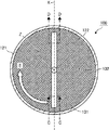
続いて、図3乃至図12を用いて篩装置100について説明する。図3は、篩装置を示す斜視図である。図4は、図3の篩装置の平面図である。図5は、図4の篩装置のA−A断面を示す断面図である。図6は、図5の篩装置のB−B断面を示す断面図である。図7は、図6の篩装置におけるブレードのC−C断面の断面形状の具体例を示した断面図である。図8は、図6の篩装置におけるブレードのD−D断面の断面形状の具体例を示した断面図である。図9は、ブレードを3枚有する回転体の正面図である。図10は、図9の回転体の平面図である。図11は、ブレードを4枚有する回転体の正面図である。図12は、図11の回転体の平面図である。篩装置100は、篩本体120と、供給部150とを有してなり、更に必要に応じて、適宜選択したその他の手段や部材を備えている。
<Sieving device>
Subsequently, the
(篩本体)
篩本体120は、筒状体の一例としてのフレーム121と、フレーム121の底部に設けられたフィルター122と、回転体130と、駆動部140とを有する。これにより、篩本体120は、フレーム121内に供給されたトナーを収容するトナー収容容器として機能する。また篩本体120は、フレーム121内に供給されたトナーから粗大粒子を篩い分ける機能を有する。篩本体120は、通常は、立てて設置させた状態で用いることが好ましいが、傾けて設置してもよい。
(Sieving body)
The
−フレーム−
フレーム121の形状としては、例えば、円筒状、円錐台形状、角筒状、角錐台形状、ホッパー形状、などが挙げられる。フレーム121の大きさは、現像装置180へのトナーの補給速度や現像ユニット10の設置スペースなどを考慮して適宜選択されるが、例えば、内径を10mm以上300mm以下、好ましくは16mm以上135mm以下とすることができる。フレーム121の材質としては、例えばステンレススチール、アルミニウム、鉄等の金属、ABS、FRP、ポリエステル樹脂、ポリプロピレン樹脂等の樹脂などが挙げられる。フレーム121の構造としては、単一部材で形成されていてもよいし、二以上の部材で形成されていてもよい。
-Frame-
Examples of the shape of the
フレーム121の側面、端面、又は上面の少なくとも一部には、供給管234dに接続する供給部121aが設けられている。供給部121aの大きさ、形状、構造等は、篩本体120内にトナーを供給することができれば、特に制限はなく、篩本体120の大きさ、形状、構造等に応じて適宜選択される。
A
また、フレーム121には、篩本体120に収容されたトナーを回収するための開口部を開閉させるクリーニング用扉121cが形成されている。クリーニング用扉121cは、篩本体120に対してヒンジにより開閉可能に取り付けられている。篩装置100の運転を停止しているときには、クリーニング用扉121cを開いてフィルター122上に残留した粗大粒子を回収することによりフィルター122のクリーニングを行うことができる。
The
−フィルター−
フィルター122としては、篩本体120に供給されたトナーに含まれる粗大粒子を篩い分けできるものであれば特に制限はなく、目的に応じて適宜選択することができる。適用可能なフィルター122の形態としては、例えば、直交網目状、斜交網目状、蛇行網目状、亀甲状等の網目の形態、不織布のような三次元に隙間を構成する形態、或いは、多孔質材料、中空糸のように実質的に粗粒が通過不可能な形態等が挙げられる。これらの中でも、網目によるフィルター122を用いることが、篩別効率が良好である点で好ましい。
-Filter-
The
フィルター122の外形状については、特に制限はなく、目的に応じて適宜選択することができ、例えば円形、楕円形、三角形、四角形、五角形、六角形、八角形などが挙げられる。これらの中でも、円形であることが篩別効率の点で特に好ましい。また、篩別操作を多段で行う場合は、目開きの異なるフィルター122を直列に設置しても良い。
There is no restriction | limiting in particular about the external shape of the
フィルター122の目開きについては、トナーの粒径に応じて適宜選択することができるが、10μm以上が好ましく、15μm以上がより好ましく、20μm以上が更に好ましい。フィルター122の目開きが小さすぎると、時間当たりの処理能力が低下しやすく、所望の粒径のトナーを効率良く得ることが困難になることがあり、また、目詰まりを生じやすい傾向がある。ここで、フィルター122の目開きとは、フィルター122網の開孔の大きさを意味し、開孔が円形の場合は直径を、多角形の場合は内接円の直径を意味する。フィルター122の目開きの上限としては、特に限定されないが、5mm以下であることが好ましい。フィルターの目開きが5mmを超えると、ブレード131の回転を停止させたときに目開き上をトナーで橋渡しすることができなくなり、トナーの排出が継続する場合がある。
The opening of the
フィルター122の材質としては、特に制限はなく、目的に応じて適宜選択することができ、例えば、ステンレススチール、アルミニウム、鉄等の金属,ナイロン等のポリアミド樹脂、ポリエステル樹脂、ポリプロピレン樹脂、アクリル樹脂等の樹脂;綿布等の天然繊維;などが挙げられる。これらの中でも、長時間使用しても、耐久性に優れる点で、ステンレススチール、ポリエステル樹脂が特に好ましい。
There is no restriction | limiting in particular as a material of the
従来の超音波篩において、樹脂製のフィルターを用いた場合、その弾性によりフィルターの振動をトナーに効率的に伝えることができなかった。また、従来の円筒状のシーブを有する篩装置は、シーブ内側領域から外側領域に遠心力によって粉体を送り出す機構を有するため、樹脂製のシーブを用いた場合には耐久性が不足する問題が生じた。本実施形態の篩装置100は、ブレード131を回転させることにより、フィルター122を振動させずにトナーを篩い分けることができる。このため、本実施形態の篩装置100には、樹脂製のフィルター122が好適に用いられる。この場合、トナーと同じ極性の樹脂により形成されたフィルター122を選択することにより、フィルター122へのトナーの付着が抑制される。
When a resin filter is used in a conventional ultrasonic sieve, the vibration of the filter cannot be efficiently transmitted to the toner due to its elasticity. In addition, since the conventional sieve device having a cylindrical sheave has a mechanism for feeding powder from the sheave inner region to the outer region by centrifugal force, there is a problem that durability is insufficient when a resin sheave is used. occured. The
また、設置されるフィルター122は、枠などの形状を保つ機構によって支持され、しわ及びたるみが少ないことが好ましい。しわ及びたるみがあると、フィルター122の破損を招く場合があるだけでなく,均一な篩い分けが困難になる場合がある。
Further, the
なお、フィルター122は、フレーム121の径方向にスライドさせることによりフレーム121に対して着脱可能な構成としても良い。これにより、フィルター122の交換が容易になるので、篩装置100のメンテナンス性が向上する。
The
−回転体−
本実施形態において、回転体130は、フィルター122と交差する回転軸Zを中心にフィルター122に近接して回転可能に配置されたブレード131と、この回転軸Zに配置されブレード131が取り付けられるシャフト132とを有する。本実施形態の篩装置100の篩本体120の内部を上から見ると、ブレード131は、図6の矢印E方向又は逆矢印方向にフィルター122の上部の近傍を、シャフト132を中心に回転可能に構成されている。これにより、ブレード131は、篩本体120内に供給されたトナーを攪拌し流動化させる。
-Rotating body-
In the present embodiment, the
本実施形態において、回転体130の構成は、回転軸Zを中心にフィルター122に近接してブレード131を回転させることが可能な構成であれば特に制限されない。例えば、シャフト132を用いずに磁力を用いてブレード131を回転させても良い。また、シャフト132とハブとを用いてブレード131を回転させてもよい。回転軸Zとフィルター122とが交差して形成される角度は、特に限定されないが、フィルター122とブレード131との距離を一定に保つことができ、接触を防ぐことができるため、90度であることが好ましい。
In the present embodiment, the configuration of the
本実施形態において、ブレード131がフィルター122に近接するとは、ブレード131の回転により発生した渦がフィルター122に到達する程度に、それぞれが近くにある状態を意味する。ただし、「近接」には、ブレード131が、回転軌道の全体でフィルター122と接している状態は含まれない。ブレード131およびフィルター122の対向面の回転軸Zと平行な二点間の距離(図3中、D1)は、0mmより大きく5mm以下が好ましく、0.01mm以上、5mm以下がより好ましく、0.5mm以上、2mm以下が更に好ましい。なお、ブレード131の回転軌道上の位置や測定点によって回転軸Zと平行な二点間の距離が変わる場合には、距離(D1)は、ブレード131のすべての回転軌道上の位置におけるすべての測定点の中で距離が最も短くなる二点間の距離を意味する。ブレード131とフィルター122との間の距離が5mmを超えると、ブレード131の回転によって発生する渦がフィルター122の面上に到達せず、クリーニングが行われなくなる場合がある。また、フィルター122に堆積させたトナーを十分に流動化できなくなることがある。なお、ブレード131とフィルター122との間の距離が0mmである場合には、ブレード131の下方のトナーがフィルター122に堆積した状態から上方へ移動することが制限されるために、トナーを十分に流動化できなくなることがある。
In the present embodiment, that the
本実施形態において、特に制限はされないが、ブレード131の端部はフレーム121に近接していることが好ましい。ブレード131の端部がフレーム121に近接しているとは、ブレード131の端部とフレーム121との間の距離(図5中、D2)が好ましくは5.0mm以下の状態であって、より好ましくは2.0mm以下の状態であって、更に好ましくは0.5mm〜1.5mmの状態である。なお、ブレード131の回転軌道上の位置や測定点によってブレード131の端部とフレーム121との間の距離が変わる場合には、距離(D2)は、ブレード131のすべての回転軌道上の位置におけるすべての測定点の中で距離が最も短くなる二点間の距離を意味する。ブレード131の端部とフレーム121との間の距離が5.0mmを超えると、ブレード131の回転による遠心力によって、トナーがフレーム121方向に流れてしまい、渦流はブレード131周辺にしか影響しないため、フレーム121側から粉体が排出されにくくなることがある。
In the present embodiment, although not particularly limited, it is preferable that the end of the
−ブレード−
本実施形態において、篩装置100はブレード131を回転させることにより、フィルター122を振動させずにトナーを篩い分けることができる。これにより、フィルター122の振動の現像装置180への伝達を抑制できるので、篩装置100を現像ユニット10に組み込むことが可能になる。
-Blade-
In the present embodiment, the
本実施形態において、ブレード131の材質、構造、大きさ、形状等については、特に制限はなく、篩本体120の大きさ、形状、構造等に応じて適宜選択される。ブレード131の材質としては、ステンレススチール、アルミニウム、鉄等の金属、ABS、FRP、ポリエステル樹脂、ポリプロピレン樹脂等の樹脂などが挙げられる。これらの中でも、強度からいうと材質は金属が好ましい。また、トナーを扱うため、防爆という観点から帯電防止剤、静電気防止剤を含有できる樹脂が好ましい。ブレード131は、単一部材で形成されていてもよいし、2以上の部材で形成されていてもよい。
In the present embodiment, the material, structure, size, shape, and the like of the
ブレード131の外形状としては、特に制限はなく、例えば、平板状、棒状、角柱状、角錐状、円柱状、円錐状、羽根状などが挙げられる。ブレード131が篩装置100に配置された場合に、回転軸Zに対して平行方向のブレード131の長さ(図5のDzで示されるブレード131の厚み)は、強度が確保できる範囲内で薄い方が好ましい。なお、ブレード131の厚み(Dz)は、ブレード131の対向面の回転軸Zと平行な二点間の距離に基づいて定められる。測定点によって回転軸Zと平行な二点間の距離が変わる場合には、ブレード131の厚み(Dz)は、すべての測定点の中で距離が最も短くなるときの二点間の距離を意味する。ブレード131の厚み(Dz)としては、例えば、0mm〜10.0mmとすることができ、0mm〜5.0mmが好ましく、0mm〜3.0mmがより好ましい。ブレード131の厚み(Dz)が5.0mmを超えると、ブレード131後方で発生する渦が少なくなり、フィルター122の面上のクリーニング性が低下する。また、厚みが10.0mmを超えると、トナーに与えられるブレード131の回転方向へのエネルギー(トナーの周方向の速度)が大きくなり、トナーのフィルター122を通過する方向(回転軸Zと平行な方向)への動きを阻害することがある。加えて、回転体130のブレード駆動用モータ141への負荷が大きくなり、より多くのエネルギーを必要とすることがある。
The outer shape of the
ブレード131の強度を保つために、ブレード131の厚さ(Dz)は、回転軸Zを中心に回転するときの回転方向のブレード131の長さ(図2のDx)よりも小さい方が好ましい。なお、ブレード131の長さ(Dx)は、ブレード131の対向面の、回転方向の二点間の距離に基づいて定められる。測定点によって回転方向の二点間の距離が変わる場合には、ブレードの長さ(Dx)は、すべての測定点の中で距離が最も短くなるときの二点間の距離を意味する。ブレード131の厚さ(Dz)がブレード131の長さ(Dx)よりも大きいと、ブレード131の回転時のトナーによる抵抗によってブレード131の強度が低下する場合がある。また、ブレード131がトナーに回転方向の速度を与えすぎてしまい、トナーがフィルター122を通過する運動を妨げる場合がある。
In order to maintain the strength of the
ブレード131の断面形状としては、特に制限はなく、目的に応じて適宜選択することができる。本実施例において、ブレード131の断面形状は、図7及び図8の断面形状A〜Gのような左右非対称な形状であっても、H〜Jのような左右対称な形状であってもよく、これらのA〜Jのいずれの形状も好適に用いることができる。ブレード131のC−C断面の形状とD−D断面の形状とは、例えば、いずれも図7のCの形状である場合のように、同一であっても良い。
There is no restriction | limiting in particular as a cross-sectional shape of the braid |
同一平面上に配置されるブレード131の枚数は、特に制限はなく、目的に応じて適宜選択される。ブレード131の枚数は、例えば、2枚(図3乃至図6参照)であっても、3枚(図9および図10参照)であっても、4枚(図11および図12参照)であっても良い。なお、図9および図10によって示される回転体130は、各ブレード131とシャフト132とがハブ133によって固定された例である。ブレード131の枚数としては、1枚〜8枚が好ましく、1枚〜4枚がより好ましく、2枚が特に好ましい。ブレード131の枚数が8枚を超えると、ブレード131がトナーのフィルター122からの落下を阻害するおそれがあり、メンテナンス性も低下する。
The number of
図6のX軸方向に見たときのブレード131のフィルター122に対する角度は、特に制限はなく、目的に応じて適宜選択することができるが、フィルター122に対して−3度〜10度が好ましく、0度〜10度がより好ましく、0度(水平)が特に好ましい。ブレード131のフィルター122に対する角度が、10度を超えると、ブレード131の後方で発生する渦が少なくなり、クリーニング性が低下する。また、トナーに与える周方向のエネルギーが大きくなり、トナーのフィルター122方向への動きを阻害することがある。加えて回転体130のブレード駆動用モータ141への負荷が大きくなることがある。
The angle of the
ブレード131が回転することで生じる軌跡の面積Xと、フィルター122の面積Yとの比率〔(X/Y)×100〕〕は、60%〜150%が好ましく、80%〜100%がより好ましい。比率〔(X/Y)×100〕〕が、60%未満であると、フィルター122の全面にブレード131の回転に伴うエネルギーが行き渡らないおそれがある。また、ブレード131の回転による遠心力によって、トナーがフレーム121側に集まり、ブレード131がトナーへエネルギーを与えることができなくなることがある。比率が150%を超えると、ブレード131の回転による遠心力によって、トナーがフィルター122より外側へ移動し、フィルター122上のトナーが減少し、篩えないことがある。
The ratio [(X / Y) × 100]] of the area X of the locus generated by the rotation of the
ブレード131の回転速度(周速)は、特に制限はなく、目的に応じて適宜選択することができるが、3m/s〜30m/sが好ましい。ブレード131の周速が、3m/s未満であると、ブレード131がトナーへ与えるエネルギーが少なく、クリーニング効果、トナーの流動化が不十分となることがあり、30m/sを超えると、トナーにエネルギーを与えすぎて、トナーの周方向の速度が大きくなり、トナーのフィルター122面方向への落下を阻害する恐れがある。また、過剰にトナーを流動化すると、フィルター122を通過するトナーの質量が小さくなることがある。
The rotational speed (circumferential speed) of the
−シャフト−
シャフト132は、篩本体120内の回転軸Zに配置され、一端が駆動部140に取り付けられ、他端がブレード131に取り付けられている。駆動部140の駆動によってブレード131及びシャフト132が回転軸Zを中心に回転する。シャフト132の大きさ、形状、構造、材質等については、特に制限はなく、篩本体120の大きさ、形状、構造等に応じて適宜選択することができる。シャフト132の材質としては、ステンレススチール、アルミニウム、鉄等の金属、ABS、FRP、ポリエステル樹脂、ポリプロピレン樹脂等の樹脂などが挙げられる。シャフト132は、単一部材で形成されていてもよいし、2以上の部材で形成されていてもよい。シャフト132の形状としては、例えば、棒状、角柱状、などが挙げられる。
-Shaft-
The
(駆動部)
本実施形態において駆動部140は、駆動手段の一例としてのブレード駆動用モータ141とベアリング142とを有している。ブレード駆動用モータ141は、ブレード131を含む回転体130を回転駆動させる。ブレード駆動用モータ141の動作は、PLC(programmable logic controller)、コンピュータ等の制御手段によって制御される。ベアリング142は、回転体130を正確に回転させるためにシャフト132を支持する手段である。トナーの進入による故障を避けるため、ベアリング142はフレーム121の外側に設けられている。シャフト132とフレーム121との間の隙間を通過して駆動部140にトナーが進入する可能性がある場合には、トナーの進入を防止する機構を設けることもできる。このような機構としては、例えば、ベアリング142とフレーム121の間にエアーを吹き込み、シャフト132とフレーム121の隙間からエアーを吹き出すことで粉体の進入を防ぐもの(エアーシール)や、駆動部140内へ粉体を進入させないためのエアー吹き出し口が挙げられる。
(Drive part)
In the present embodiment, the driving
また、駆動部140には、装置を停止したときに回転体130の回転を停止させる公知のブレーキ機構が設けられていても良い。装置を停止したときにブレーキ機構によってブレード131の回転を停止させることで、トナーの流動化が即時に収まるため、篩装置100による現像装置180へのトナーの補給の精度が向上する。
The
本実施形態に係る篩装置100は、超音波や振動波によってフィルター122を振動させる必要がないので、摩擦熱によって軟化または凝集した粉体によるフィルター122の目詰まりの発生や、摩擦のストレスによるフィルター122の目開きの拡大を抑制できる。
Since the
(供給部)
本実施形態において供給部150は、導入手段の一例としてのノズル151とトナーセンサ152とを備えている。ノズル151は、サブホッパ160に接続し、ブレード131の回転に基づいてフィルター122を通過したトナーをサブホッパ160に導入させる装置である。ノズル151の構成部材としては、トナーを現像装置180に導入することにより供給できるものであれば特に制限はないが、例えばステンレス管が挙げられる。ノズル151は、サブホッパ160の上面の端部に形成されたトナー導入口に嵌合させる嵌合部151aを有している。嵌合部151aにはノズル151を正確にトナー導入口に嵌合させるため例えばパッキンが取り付けられていても良い。また、サブホッパ160のトナー導入口が小さい場合には、嵌合部151aから直接サブホッパ160にトナーを導入する構成を、ファンネルを介してトナーを導入する構成に置き換えても良い。
(Supply section)
In the present embodiment, the
トナーセンサ152は、フィルター122を通過したトナーを検知する。トナーセンサ152としては、公知のものが用いられ、透磁率に基づいてトナーを検知するものや、透過率を用いてトナーを検知するもの等が例示される。
The
<サブホッパ>
続いて、図13乃至図15を用いてサブホッパ160について説明する。図13は、サブホッパの正面図である。図14は、図13のサブホッパのF−F断面を示す断面図である。図15は、図13のサブホッパのG−G断面を示す断面図である。サブホッパ160は、トナーを現像装置180に補給するための補給口A4が形成された底板161aと、底板161aの周囲に立設された筒状体としてのサブホッパフレーム161bと、サブホッパフレーム161bの上部開口に設けられ、ブレード131の回転に基づいてフィルター122を通過したトナーを導入するための導入口A1を有する天板161cと、を有するサブホッパ本体161と、導入口A1から導入されたトナーを補給口A4に搬送する搬送手段としての第1上スクリュー163、第2上スクリュー164、及び下スクリュー167と、を備える。本実施形態において「立設」とは、立った状態で設けることを意味し、例えば、底板161aに対して0度よりも大きく180度よりも小さい角度でサブホッパフレーム161bが設けられた状態を意味する。第1上スクリュー163、第2上スクリュー164、及び下スクリュー167は、サブホッパフレーム161bの各対向面に支持されて、架け渡されている。第1上スクリュー163、第2上スクリュー164、及び下スクリュー167は、それぞれギア(163a,164a,167a)によって連結し、駆動手段としてのモータの駆動によって連動して回転する。
<Sub hopper>
Subsequently, the
サブホッパ160の内部には、上下仕切板161dによって上下に分割されることにより、それぞれトナーを収容する収容手段としての上室162と下室166とが設けられている。第1上スクリュー163の支持部A5の上方に近接する天板161cには、導入口A1が形成されている。これにより、サブホッパ160の支持部A5側の上方に篩装置100が配置されるため、サブホッパ160の支持部A5の対向面側の上方に中間転写ベルト243を配置することが可能となる。導入口A1に導入されたトナーは第1上スクリュー163及び第2上スクリュー164の回転によって図14の矢印s1方向に搬送される。搬送されたトナーは連通孔(A2,A3)を通過して下室166に落下する。
Inside the
連通孔A3を通過して上室162から落下したトナーは、下スクリュー167の回転によって図15の矢印s2の方向に搬送される。搬送されたトナーは補給口A4から落下して現像装置180に補給される。
The toner that has passed through the communication hole A3 and dropped from the
<現像装置>
続いて、図16及び図17を用いて現像装置180について説明する。図16は、現像装置を示す横断面図である。図17は、現像装置を示す縦断面図である。現像装置180は、図16に示すように第1収容部181に設けられた第1搬送スクリュー182と、第2収容部183に設けられた第2搬送スクリュー184と、現像ロール185と、及びドクターブレード186とを有する。第1収容部181および第2収容部は予め磁性キャリアを収容している。
<Developing device>
Subsequently, the developing
図16の符号B1で示す位置の上方にはサブホッパ160の補給口A4と接続した補給口B1が形成されている。第1搬送スクリュー182は、モータなどの駆動手段によって回転駆動することで、補給口B1を経て補給されたトナー、及び磁性キャリアからなる現像剤を図16中の左側から右側へと搬送する。搬送された現像剤は、第1収容部181と第2収容部183との仕切壁の一部に形成された連通孔B2を経て第2収容部183内に進入する。第2搬送スクリュー184は、モータなどの駆動手段によって回転駆動することで現像剤を図16中の右側から左側へと搬送する。
A supply port B1 connected to the supply port A4 of the
現像ロール185は、マグネットローラを内包する。このマグネットローラの発する磁力によって、第2収容部183内を搬送される現像剤は、現像ロール185に吸着する。現像ロール185に吸着した現像剤は、現像ロール185の図17中の矢印方向への回転に伴い搬送され、ドクターブレード186によってその層厚が規制される。層厚が規制された現像剤は、感光ドラム231に対向する位置に搬送され、感光ドラム231の担持する静電潜像に付着する。この付着により感光ドラム231上にトナー像が形成される。現像によってトナーを消費した現像剤は、現像ロール185の回転に伴って回転し、第2収容部183に戻される。さらに、トナーを消費した現像剤は第2搬送スクリュー184によって第2収容部183内を図16中右側から左側へと搬送され、連通孔B3を経て第1収容部181内に戻される。
The developing
<制御部>
続いて、図18、及び図19を用いて制御部500について説明する。なお、図18は、制御部のハードウェア構成図である。図19は、制御部の機能ブロック図である。
<Control unit>
Subsequently, the
まず、制御部500のハードウェア構成について説明する。図18に示したように、制御部500は、画像形成装置1全体の動作を制御するCPU501、画像形成装置1を動作させるためのプログラムを記憶したROM502、CPU501のワークエリアとして使用されるRAM503、画像形成装置1の電源が遮断されている間もデータを保持する不揮発性メモリ(NVRAM)504、ホストコンピュータ等の外部機器との情報の送受信を行うためのI/F(Interface)506、篩装置100のブレード駆動用モータ141、サブホッパ160の駆動手段、トナーセンサ152、吸引ポンプ234c、及び操作パネル510との情報の送受信を行うためのI/O(Input/Output)ポート507を有する。
First, the hardware configuration of the
続いて、制御部500の機能構成について説明する。図19に示したように、制御部500は、駆動制御部561、搬送制御部562、及び供給制御部563を有している。これら各部は、図18に示されている各構成要素のいずれかが、ROM502に記憶されているプログラムに従ったCPU501からの命令によって動作することで実現される機能又は手段である。
Next, the functional configuration of the
駆動制御部561は、トナーセンサ152の検知結果に基づいて、ブレード駆動用モータ141によるブレード131の回転駆動を制御する。搬送制御部562は、サブホッパ160によるトナーの搬送を制御する。供給制御部563は、吸引ポンプ234cによるトナーの吸引を制御する。
The
<現像剤>
続いて現像ユニット10に用いられる現像剤について説明する。現像ユニット10に用いられる現像剤としては、特に制限はなく、目的に応じて適宜選択される。現像剤の具体例としては、トナーを有する一成分系の現像剤や、トナーと磁性キャリアとを有する二成分系の現像剤であっても良い。上記のトナーとしては、イエロー、シアン、マゼンタ、ブラックなどの有色トナー、及びクリアトナーが挙げられる。
<Developer>
Next, the developer used in the developing
−トナー−
上記のトナーの製造方法については、特に制限はなく、目的に応じて適宜選択することができるが、湿式法により調製されたものが好ましい。湿式法とは、トナー母粒子の製造工程において、水等の分散媒等を用いる静電荷像現像用トナーの製造方法である。湿式法としては、以下の方法が例示される。
-Toner-
There is no restriction | limiting in particular about the manufacturing method of said toner, Although it can select suitably according to the objective, What was prepared by the wet method is preferable. The wet method is a method for producing an electrostatic charge image developing toner using a dispersion medium such as water in the production process of toner base particles. Examples of the wet method include the following methods.
(a)水系媒体中に重合性単量体、重合開始剤、着色剤等を懸濁分散させた後に重合させてトナー母粒子を製造する懸濁重合法
(b)重合開始剤、乳化剤等を含有する水性媒体中に重合性単量体を乳化させ、攪拌下に重合性単量体を重合させて得られた重合体一次粒子の分散液に、着色剤等を添加して重合体一次粒子を凝集、熟成させてトナー母粒子を製造する乳化重合凝集法
(c)あらかじめ溶媒に溶解、分散したポリマー、着色剤等の溶解分散液(トナー組成の溶解分散液)を水系媒体中に分散し、これを加熱又は減圧等によって溶媒を除去することにより、水系媒体に分散されたトナー母粒子を製造する溶解懸濁法
(A) Suspension polymerization method in which a polymerizable monomer, a polymerization initiator, a colorant and the like are suspended and dispersed in an aqueous medium and then polymerized to produce toner mother particles (b) A polymerization initiator, an emulsifier, etc. A polymer primary particle is obtained by adding a colorant or the like to a dispersion of polymer primary particles obtained by emulsifying a polymerizable monomer in an aqueous medium and polymerizing the polymerizable monomer with stirring. (C) Disperse a dispersion of a polymer, a colorant, etc. (dissolved dispersion of toner composition) previously dissolved and dispersed in a solvent in an aqueous medium. And a suspension method for producing toner mother particles dispersed in an aqueous medium by removing the solvent by heating or reducing the pressure.
トナーを構成する成分としては、下記(1)〜(4)から選択されるいずれかの混合物が好適である。
(1)少なくとも結着樹脂、及び着色剤からなる混合物
(2)少なくとも結着樹脂、着色剤、及び帯電制御剤からなる混合物
(3)少なくとも結着樹脂、着色剤、帯電制御剤、及びワックスからなる混合物
(4)少なくとも結着樹脂、磁性剤、帯電制御剤、及びワックスからなる混合物
As the component constituting the toner, any mixture selected from the following (1) to (4) is suitable.
(1) A mixture comprising at least a binder resin and a colorant (2) A mixture comprising at least a binder resin, a colorant and a charge control agent (3) From at least a binder resin, a colorant, a charge control agent and a wax (4) A mixture comprising at least a binder resin, a magnetic agent, a charge control agent, and a wax
結着樹脂としては、特に制限はなく、目的に応じて適宜選択することができるが、熱可塑性樹脂が好適である。熱可塑性樹脂としては、例えば、ビニル樹脂、ポリエステル樹脂、ポリオール樹脂などが挙げられる。これらは、1種単独で使用してもよいし、2種以上を併用してもよい。これらの中でも、ポリエステル樹脂、ポリオール樹脂が特に好ましい。 There is no restriction | limiting in particular as binder resin, Although it can select suitably according to the objective, A thermoplastic resin is suitable. Examples of the thermoplastic resin include a vinyl resin, a polyester resin, and a polyol resin. These may be used individually by 1 type and may use 2 or more types together. Among these, polyester resins and polyol resins are particularly preferable.
ビニル樹脂としては、例えばポリスチレン、ポリ−p−クロロスチレン、ポリビニルトルエン等のスチレン又はその置換体の単重合体:スチレン−p−クロロスチレン共重合体、スチレン−プロピレン共重合体、スチレン−ビニルトルエン共重合体、スチレン−ビニルナフタリン共重合体、スチレン−アクリル酸メチル共重合体、スチレン−アクリル酸エチル共重合体、スチレン−アクリル酸ブチル共重合体、スチレン−アクリル酸オクチル共重合体、スチレン−メタクリル酸メチル共重合体、スチレン−メタクリル酸エチル共重合体、スチレン−メタクリル酸ブチル共重合体、スチレン−α−クロロメタクリル酸メチル共重合体、スチレン−アクリロニトリル共重合体、スチレン−ビニルメチルエーテル共重合体、スチレン−ビニルエチルエーテル共重合体、スチレン−ビニルメチルケトン共重合体、スチレン−ブタジエン共重合体、スチレン−イソプレン共重合体、スチレン−アクリロニトリル−インデン共重合体、スチレン−マレイン酸共重合体、スチレン−マレイン酸エステル共重合体等のスチレン系共重合体;ポリメチルメタクリレート、ポリブチルメタクリレート、ポリ塩化ビニル、ポリ酢酸ビニルなどが挙げられる。 Examples of the vinyl resin include styrene such as polystyrene, poly-p-chlorostyrene, and polyvinyltoluene, or a homopolymer of a substituted product thereof: styrene-p-chlorostyrene copolymer, styrene-propylene copolymer, styrene-vinyltoluene. Copolymer, Styrene-vinylnaphthalene copolymer, Styrene-methyl acrylate copolymer, Styrene-ethyl acrylate copolymer, Styrene-butyl acrylate copolymer, Styrene-octyl acrylate copolymer, Styrene- Methyl methacrylate copolymer, styrene-ethyl methacrylate copolymer, styrene-butyl methacrylate copolymer, styrene-α-chloromethyl methacrylate copolymer, styrene-acrylonitrile copolymer, styrene-vinyl methyl ether copolymer Polymer, styrene-vinylethyl -Ter copolymer, styrene-vinyl methyl ketone copolymer, styrene-butadiene copolymer, styrene-isoprene copolymer, styrene-acrylonitrile-indene copolymer, styrene-maleic acid copolymer, styrene-maleic acid ester Examples thereof include styrene copolymers such as copolymers; polymethyl methacrylate, polybutyl methacrylate, polyvinyl chloride, and polyvinyl acetate.
ポリエステル樹脂としては、以下のA群に示したような2価のアルコールと、B群に示したような二塩基酸塩からなるものであり、更にC群に示したような3価以上のアルコールあるいはカルボン酸を第三成分として加えてもよい。 The polyester resin is composed of a dihydric alcohol as shown in the following group A and a dibasic acid salt as shown in the group B, and further a trihydric or higher alcohol as shown in the group C. Alternatively, carboxylic acid may be added as a third component.
A群としては、例えばエチレングリコール、トリエチレングリコール、1,2−プロピレングリコール、1,3−プロピレングリコール、1,4−ブタンジオール、ネオペンチルグリコール、1,4−ブテンジオール、1,4−ビス(ヒドロキシメチル)シクロヘキサン、ビスフェノールA、水素添加ビスフェノールA、ポリオキシエチレン化ビスフェノールA、ポリオキシプロピレン(2,2)−2,2’−ビス(4−ヒドロキシフェニル)プロパン、ポリオキシプロピレン(3,3)−2,2−ビス(4−ヒドロキシフェニル)プロパン、ポリオキシエチレン(2,0)−2,2−ビス(4−ヒドロキシフェニル)プロパン、ポリオキシプロピレン(2,0)−2,2’−ビス(4−ヒドロキシフェニル)プロパンなどが挙げられる。 Examples of Group A include ethylene glycol, triethylene glycol, 1,2-propylene glycol, 1,3-propylene glycol, 1,4-butanediol, neopentyl glycol, 1,4-butenediol, 1,4-bis. (Hydroxymethyl) cyclohexane, bisphenol A, hydrogenated bisphenol A, polyoxyethylenated bisphenol A, polyoxypropylene (2,2) -2,2′-bis (4-hydroxyphenyl) propane, polyoxypropylene (3, 3) -2,2-bis (4-hydroxyphenyl) propane, polyoxyethylene (2,0) -2,2-bis (4-hydroxyphenyl) propane, polyoxypropylene (2,0) -2,2 Examples include '-bis (4-hydroxyphenyl) propane.
B群としては、例えばマレイン酸、フマル酸、メサコニン酸、シトラコン酸、イタコン酸、グルタコン酸、フタル酸、イソフタル酸、テレフタル酸、シクロヘキサンジカルボン酸、コハク酸、アジピン酸、セバチン酸、マロン酸、リノレイン酸、又はこれらの酸無水物又は低級アルコールのエステルなどが挙げられる。 Examples of group B include maleic acid, fumaric acid, mesaconic acid, citraconic acid, itaconic acid, glutaconic acid, phthalic acid, isophthalic acid, terephthalic acid, cyclohexanedicarboxylic acid, succinic acid, adipic acid, sebacic acid, malonic acid, linolein. Examples include acids or acid anhydrides or esters of lower alcohols.
C群としては、例えばグリセリン、トリメチロールプロパン、ペンタエリスリトール等の3価以上のアルコール;トリメリット酸、ピロメリット酸等の3価の以上のカルボン酸などが挙げられる。 Examples of the group C include trivalent or higher alcohols such as glycerin, trimethylolpropane, and pentaerythritol; and trivalent or higher carboxylic acids such as trimellitic acid and pyromellitic acid.
ポリオール樹脂としては、例えばエポキシ樹脂と2価フェノールのアルキレンオキサイド付加物、もしくはそのグリシジルエーテルとエポキシ基と反応する活性水素を分子中に1個有する化合物と、エポキシ樹脂と反応する活性水素を分子中に2個以上有する化合物を反応してなるものなどが挙げられる。 Examples of the polyol resin include an alkylene oxide adduct of an epoxy resin and a dihydric phenol, or a compound having one active hydrogen in the molecule that reacts with the glycidyl ether and the epoxy group, and an active hydrogen that reacts with the epoxy resin in the molecule. And the like obtained by reacting two or more compounds.
その他にも必要に応じて以下の樹脂を混合して使用することもできる。エポキシ樹脂、ポリアミド樹脂、ウレタン樹脂、フェノール樹脂、ブチラール樹脂、ロジン、変性ロジン、テルペン樹脂などが挙げられる。エポキシ樹脂としては、例えばビスフェノールA、ビスフェノールF等のビスフェノールとエピクロロヒドリンとの重縮合物が代表的である。 In addition, the following resins can be mixed and used as necessary. Examples thereof include an epoxy resin, a polyamide resin, a urethane resin, a phenol resin, a butyral resin, a rosin, a modified rosin, and a terpene resin. Typical examples of the epoxy resin include polycondensates of bisphenol such as bisphenol A and bisphenol F and epichlorohydrin.
着色剤としては、特に制限はなく、公知のものの中から目的に応じて適宜選択することができるが、例えば、以下のものが用いられる。これらは、1種単独で使用してもよいし、2種以上を併用してもよい。 There is no restriction | limiting in particular as a coloring agent, Although it can select suitably according to the objective from well-known things, For example, the following are used. These may be used individually by 1 type and may use 2 or more types together.
黒色顔料としては、例えばカーボンブラック、オイルファーネスブラック、チャンネルブラック、ランプブラック、アセチレンブラック、アニリンブラック等のアジン系色素、金属塩アゾ色素、金属酸化物、複合金属酸化物などが挙げられる。黄色顔料としては、例えばカドミウムイエロー、ミネラルファストイエロー、ニッケルチタンイエロー、ネーブルスイエロー、ナフトールイエローS、ハンザイエローG、ハンザイエロー10G、ベンジジンイエローGR、キノリンイエローレーキ、パーマネントイエローNCG、タートラジンレーキなどが挙げられる。橙色顔料としては、例えばモリブデンオレンジ、パーマネントオレンジGTR、ピラゾロンオレンジ、バルカンオレンジ、インダンスレンブリリアントオレンジRK、ベンジジンオレンジG、インダンスレンブリリアントオレンジGKなどが挙げられる。赤色顔料としては、例えばベンガラ、カドミウムレッド、パーマネントレッド4R、リソールレッド、ピラゾロンレッド、ウォッチングレッドカルシウム塩、レーキレッドD、ブリリアントカーミン6B、エオシンレーキ、ローダミンレーキB、アリザリンレーキ、ブリリアントカーミン3Bなどが挙げられる。紫色顔料としては、例えばファストバイオレットB、メチルバイオレットレーキなどが挙げられる。青色顔料としては、例えばコバルトブルー、アルカリブルー、ビクトリアブルーレーキ、フタロシアニンブルー、無金属フタロシアニンブルー、フタロシアニンブルー部分塩素化物、ファーストスカイブルー、インダンスレンブルーBCなどが挙げられる。緑色顔料としては、例えば、クロムグリーン、酸化クロム、ピグメントグリーンB、マラカイトグリーンレーキなどが挙げられる。着色剤の含有量は、結着樹脂100質量部に対し0.1質量部〜50質量部が好ましく、5質量部〜20質量部がより好ましい。 Examples of the black pigment include azine dyes such as carbon black, oil furnace black, channel black, lamp black, acetylene black, and aniline black, metal salt azo dyes, metal oxides, and composite metal oxides. Examples of yellow pigments include cadmium yellow, mineral fast yellow, nickel titanium yellow, navel yellow, naphthol yellow S, Hansa Yellow G, Hansa Yellow 10G, Benzidine Yellow GR, Quinoline Yellow Lake, Permanent Yellow NCG, Tartrazine Lake, etc. Can be mentioned. Examples of the orange pigment include molybdenum orange, permanent orange GTR, pyrazolone orange, Vulcan orange, indanthrene brilliant orange RK, benzidine orange G, indanthrene brilliant orange GK and the like. Examples of red pigments include Bengala, Cadmium Red, Permanent Red 4R, Resol Red, Pyrazolone Red, Watching Red Calcium Salt, Lake Red D, Brilliant Carmine 6B, Eosin Lake, Rhodamine Lake B, Alizarin Lake, Brilliant Carmine 3B and the like. It is done. Examples of purple pigments include Fast Violet B and Methyl Violet Lake. Examples of blue pigments include cobalt blue, alkali blue, Victoria blue lake, phthalocyanine blue, metal-free phthalocyanine blue, phthalocyanine blue partially chlorinated, first sky blue, and indanthrene blue BC. Examples of the green pigment include chrome green, chromium oxide, pigment green B, and malachite green lake. The content of the colorant is preferably 0.1 part by mass to 50 parts by mass, and more preferably 5 parts by mass to 20 parts by mass with respect to 100 parts by mass of the binder resin.
ワックスは、トナーに離型性を持たせるために添加され、特に制限はなく、公知のものの中から目的に応じて適宜選択することができるが、例えば低分子量のポリエチレン、ポリプロピレン等の合成ワックス;カルナウバワックス、ライスワックス、ラノリン等の天然ワックスなどが挙げられる。ワックスの含有量は、トナー100質量部に対し、1質量%〜20質量%が好ましく、3質量%〜10質量%がより好ましい。 The wax is added to give the toner releasability and is not particularly limited and can be appropriately selected from known ones according to the purpose. For example, synthetic waxes such as low molecular weight polyethylene and polypropylene; And natural waxes such as carnauba wax, rice wax, and lanolin. The content of the wax is preferably 1% by mass to 20% by mass and more preferably 3% by mass to 10% by mass with respect to 100 parts by mass of the toner.
帯電制御剤としては、特に制限はなく、目的に応じて適宜選択することができ、例えば、ニグロシン、アセチルアセトン金属錯体、モノアゾ金属錯体、ナフトエ酸、脂肪酸金属塩(サリチル酸の金属塩、サリチル酸誘導体の金属塩)、トリフェニルメタン系染料、モリブデン酸キレート顔料、ローダミン系染料、アルコキシ系アミン、4級アンモニウム塩(フッ素変性4級アンモニウム塩を含む)、アルキルアミド、燐の単体又はその化合物、タングステンの単体又はその化合物、フッ素系活性剤、などが挙げられる。これらは、1種単独で使用してもよいし、2種以上を併用してもよい。帯電制御剤の含有量は、トナー100質量部に対し、0.1質量%〜10質量%が好ましく、0.5質量%〜5質量%がより好ましい。 The charge control agent is not particularly limited and may be appropriately selected depending on the purpose. For example, nigrosine, acetylacetone metal complex, monoazo metal complex, naphthoic acid, fatty acid metal salt (metal salt of salicylic acid, metal of salicylic acid derivative) Salt), triphenylmethane dyes, molybdate chelate pigments, rhodamine dyes, alkoxy amines, quaternary ammonium salts (including fluorine-modified quaternary ammonium salts), alkylamides, phosphorus alone or compounds thereof, tungsten alone Or the compound, a fluorine-type activator, etc. are mentioned. These may be used individually by 1 type and may use 2 or more types together. The content of the charge control agent is preferably 0.1% by mass to 10% by mass and more preferably 0.5% by mass to 5% by mass with respect to 100 parts by mass of the toner.
更に、トナーには、流動性を付与するために、シリカ微粉末、酸化チタン微粉末等の無機微粉末を外添させることできる。 Furthermore, inorganic fine powders such as silica fine powder and titanium oxide fine powder can be externally added to the toner in order to impart fluidity.
トナーの個数平均粒径としては、3.0μm〜10.0μmが好ましく、4.0μm〜7.0μmがより好ましい。また、トナーの重量平均粒径と個数平均粒径との比(重量平均粒径/個数平均粒径)は、1.03〜1.5が好ましく、1.06〜1.2がより好ましい。ここで、トナーの個数平均粒径、及び、重量平均粒径と個数平均粒径との比(重量平均粒径/個数平均粒径)は、例えば、「コールターカウンターマルチサイザー」;ベックマンコールター社製を用いて測定することができる。 The number average particle diameter of the toner is preferably 3.0 μm to 10.0 μm, and more preferably 4.0 μm to 7.0 μm. Further, the ratio of the weight average particle diameter to the number average particle diameter (weight average particle diameter / number average particle diameter) of the toner is preferably 1.03 to 1.5, and more preferably 1.06 to 1.2. Here, the number average particle diameter of the toner and the ratio of the weight average particle diameter to the number average particle diameter (weight average particle diameter / number average particle diameter) are, for example, “Coulter Counter Multisizer”; manufactured by Beckman Coulter, Inc. Can be measured.
−磁性キャリア−
磁性キャリアとしては、磁性材料を含有するものであれば、特に制限はなく、目的に応じて適宜選択される。磁性キャリアの具体例としては、ヘマタイト、鉄粉、マグネタイト、フェライト等が挙げられる。磁性キャリアの含有量は、トナー100質量部に対し、5質量%〜50質量%が好ましく、10質量%〜30質量%がより好ましい。
-Magnetic carrier-
The magnetic carrier is not particularly limited as long as it contains a magnetic material, and is appropriately selected according to the purpose. Specific examples of the magnetic carrier include hematite, iron powder, magnetite, and ferrite. The content of the magnetic carrier is preferably 5% by mass to 50% by mass and more preferably 10% by mass to 30% by mass with respect to 100 parts by mass of the toner.
<<<実施形態の動作・処理>>>
次に、図20乃至図23を参照して、画像形成装置1の動作及び処理について説明する。図20は、画像形成装置の処理を示した処理フロー図である。図21は、図3の篩装置にトナーを供給した状態を示す概略図である。図22及び図23は、図3の篩装置でトナーの篩い分けを行っている状態を示す概略図である。
<<< Operation and Processing of Embodiment >>>
Next, the operation and processing of the
<<印刷開始時の動作・処理>>
操作パネル510又はI/F506によって印刷開始の要求が受け付けられると、駆動制御部561は、トナーセンサ152から送信される信号に基づいてトナーセンサ152がトナーを検知しているか否かを判断する(ステップS11)。トナーセンサ152がトナーを検知していると判断された場合には(ステップS11のYES)、サブホッパ160が十分な量のトナーを収容しているので、篩装置100は、サブホッパ160へのトナーの供給を開始しない。
<< Operation and processing at the start of printing >>
When a print start request is received by the
トナーセンサ152がトナーを検知していないと判断された場合には(ステップS11のNO)、サブホッパ160内のトナーの量が不足しているため、篩装置100は、サブホッパ160へのトナーの供給を開始する。この場合、駆動制御部561は、ブレード131の回転駆動を開始するための信号をブレード駆動用モータ141に出力する(ステップS12)。ブレード駆動用モータ141は、出力された信号に基づいて回転体130を回転駆動する。これにより、シャフト132が回転し、シャフト132の先端に取り付けられたブレード131が回転軸Zを中心にフィルター122に近接して回転する。回転速度としては、特に限定されないが、500rpm〜4,000rpmである。本実施形態では、トナーカートリッジ234から篩装置100へのトナーの供給を開始する前にブレード131を回転させておくことで、先の操作でフィルター122上に残された粗大粒子を流動化させることができる。これにより、フィルター122面がクリーニングされるので、トナーの供給を開始したときに篩装置100は、篩い分け処理を効率的に実行することができる。
If it is determined that the
続いて、供給制御部563は、吸引を開始するための信号を吸引ポンプ234cに送信する(ステップS13)。これにより吸引ポンプ234cによるトナーの吸引が開始して、トナーカートリッジ234内のトナーが供給管234dを経て篩装置100に供給される。
Subsequently, the supply control unit 563 transmits a signal for starting suction to the
トナーカートリッジ234から供給されたトナーは、図21に示すように、供給部121aを介して、篩本体120のフレーム121内に一定量供給される(供給工程)。これにより、トナーPがフレーム121内に収容されフィルター122上に堆積する。このとき、フィルターの目開きと粒径とが一定以下の比率であるとき、フィルターの目開きよりも粒径の小さい粉体Pについても、粒同士がお互いに支えあい(ブリッジ)、フィルター122上に堆積する。ブレード131は、フィルター122上に堆積したトナー中を回転することにより、トナーを攪拌し流動化させる(攪拌工程,図22参照)。このとき、粉体Pが堆積した篩本体120中でブレード131が速度を持つことで、ブレード131の進行方向に対し後方に渦Vが発生する。ここで、渦とは、流体中で固体を動かした時にその後方に交互及びランダムに発生する流体の流れを意味する。
As shown in FIG. 21, the toner supplied from the
フィルター122に堆積した粗大粒子Pcは、ブレード131と接触して解砕されるとともに、ブレード131の回転により発生した渦Vによって巻き上げられる(図22参照,フィルター面のクリーニング作用)。小粒径のトナーPsは、このクリーニング作用によってフィルター122を通過しやすくなる。また、図23に示す流動化したトナーPfは、渦Vよって空気が混ぜ合わされて嵩密度が低くなる。これにより、流動化したトナーPfが自重により落下したときに、小粒径のトナーPsが、低ストレスな状態で効率良くフィルター122を通過する。フィルター122を通過したトナーPsは、ノズル151を通過してサブホッパ160に導入される。
Coarse particles Pc deposited on the
トナーセンサ152がトナーを検知していると判断された場合(ステップS11のYES)、或いは、ステップS13で吸引ポンプ234cによる吸引を開始させた後に、搬送制御部562は、サブホッパ160によるトナーの補給を制御する(ステップS14)。この制御は、搬送制御部562が、第1上スクリュー163、第2上スクリュー164、及び下スクリュー167を回転駆動するための信号を各スクリューを駆動する駆動手段に出力することによって実行される。これにより、サブホッパ160から現像装置180に高精度にトナーが補給されて、現像装置180に収容されたトナーの濃度が一定に調整される。
If it is determined that the
現像装置180は、サブホッパ160によって補給されたトナーを用いて、感光ドラム231上に形成された静電潜像をトナー像に現像する(現像工程)。転写部240では、一次転写ローラ244に一次転写バイアスがかけられ、感光ドラム231の表面に形成された各トナー像が中間転写ベルト243上に転写(一次転写)される。また、二次転写ローラ246に二次転写バイアスがかけられることで、二次転写ローラ246と二次対向ローラ245とに挟み込まれた搬送中の用紙に中間転写ベルト243上のトナー像が転写(二次転写)される(転写工程)。トナー像が転写された用紙は、加熱ローラ251によって定着下限温度よりも高い温度に加熱されるとともに、加圧ローラ252によって加圧される。これにより、溶融したトナー像が用紙に定着する(定着工程)。
The developing
<<印刷終了時の動作・処理>>
続いて、印刷終了時の画像形成装置1の動作・処理について図24を用いて説明する。図24は、画像形成装置の処理を示した処理フロー図である。
<< Operation and processing at the end of printing >>
Next, the operation and processing of the
操作パネル510又はI/F506によって受け付けられた要求に基づく印刷が完了すると、供給制御部563は、トナーカートリッジ234からのトナーの吸引を停止するための信号を吸引ポンプ234cに送信する(ステップS21)。これにより吸引ポンプ234cによるトナーの吸引が停止して、トナーカートリッジ234から篩装置100へのトナーの供給が停止する。
When the printing based on the request received by the
トナーカートリッジ234から篩装置100へのトナーの供給を停止させた状態で、ブレード131を回転させておくことで、ブレード131がフィルター122に堆積したトナーを排出させ、フィルター122面をクリーニングする。この場合、フィルター122を通過しなかった粗大粒子が遠心力でフレーム121側に移動する。
The
続いて、駆動制御部561は、ブレード131の回転を停止するための信号をブレード駆動用モータ141に出力する(ステップS22)。ブレード駆動用モータ141は出力された信号に基づいて回転体130を回転駆動を停止する。これにより、篩装置100によるサブホッパ160へのトナーの供給が停止する。この場合、粗大粒子が遠心力でフレーム121側に移動しているのでクリーニング用扉121cから粗大粒子を容易に回収することができる。
Subsequently, the
〔第2の実施形態〕
以下、図25を用いて、本発明の第2の実施形態に係る篩装置について、第1の実施形態に係る篩装置と異なる点を説明する。図25は、本発明の一実施形態に係る篩装置を示す断面図である。なお、図25において、第1の実施形態に係る篩装置と共通する構成については、同じ符号を用いて示し、詳細な説明を省略する。
[Second Embodiment]
Hereinafter, the difference between the sieving apparatus according to the first embodiment and the sieving apparatus according to the first embodiment will be described with reference to FIG. FIG. 25 is a cross-sectional view showing a sieving device according to an embodiment of the present invention. In addition, in FIG. 25, about the structure which is common in the sieve apparatus which concerns on 1st Embodiment, it shows using the same code | symbol and abbreviate | omits detailed description.
図25の篩装置101は、フレーム121に排出部121bが形成されている点以外は、第1の実施形態の篩装置100と同様である。
The
<排出部>
フレーム121には、篩本体120に収容されフィルター122に堆積したトナーが所定量を超える場合に、所定量を超えるトナーを篩本体120から排出する排出部121bが設けられている。フィルター122を通過するトナーの量より供給部121aから供給されるトナーの量が過多の場合、フィルター122に堆積するトナーの量が増え続ける。本実施形態では、排出部121bを設けることで、所定量を超える過剰なトナーが外部に排出されるため、篩装置101の長時間連続運転が可能となり、効率よく大容量のトナーの篩分けを行うことができる。
<Discharge unit>
The
排出部121bとしては、篩本体120から過剰なトナーを排出することができれば、大きさ、形状、構造、材質等については、特に制限はなく、篩本体120の大きさ、形状、構造等に応じて適宜選択することができる。排出部121bの材質としては、ステンレススチール、アルミニウム、鉄等の金属、ABS、FRP、ポリエステル樹脂、ポリプロピレン樹脂等の樹脂などが挙げられる。排出部121bの形状及び大きさについても、特に制限はなく、目的に応じて適宜選択することができる。排出部121bは、フレーム121のトナー供給側の側面、端面及び上面のいずれかに形成されることが好ましい。排出部121bから排出されたトナーは、そのまま供給部121aから補充され、再度篩分されるように構成してもよい。
There are no particular restrictions on the size, shape, structure, material, and the like of the
〔実施形態の補足〕
以上、各実施形態の篩装置(100,101)について詳細に説明したが、本発明は上記各実施形態に限定されず、本発明の要旨を逸脱しない範囲で種々変更しても差支えない。例えば、上記の各実施形態では、シャフト132に1段のブレード131が設けられていたが、必要に応じてシャフト132の高さの異なる位置に2段のブレード131が設けられても構わない。
[Supplement of Embodiment]
As mentioned above, although the sieve apparatus (100, 101) of each embodiment was demonstrated in detail, this invention is not limited to said each embodiment, A various change may be made in the range which does not deviate from the summary of this invention. For example, in each of the above-described embodiments, the one-
また、上記の各実施形態では、フィルター122は、図5及び図25に示すように、篩本体120のトナー排出側端面の全面に設けられていたが、本発明の篩装置はこの構成に限定されない。フィルター122は、篩本体120のトナー排出側端面の一部に設けられていてもよい。
In each of the above embodiments, as shown in FIGS. 5 and 25, the
上記実施形態において、トナーを現像装置180に供給する装置としてサブホッパ160を用いた。しかしながら、本発明は上記の実施形態に限定されない。上記実施形態のサブホッパ160は、ベローズ式ポンプやダイヤフラム式ポンプ、スネーク式ポンプ等のポンプ、圧縮空気による圧送、コイルスクリューやオーガ等の手段、若しくは自重落下を利用してトナーを供給する構成に置き換えられる。
In the above embodiment, the
〔実施形態の効果〕
上記実施形態に係る篩装置(100,101)は、フィルター122と交差する回転軸Zを中心にフィルター122に近接して回転するブレード131を備える。これにより、現像装置180は予め粗大粒子が篩い分けられたトナーを用いてトナー像を現像するので、形成される画像の画質が粗大粒子によって低下することを防ぐことができるという効果を奏する。また、ブレード131の回転に基づいてトナーがフィルター122を通過するときのトナーの移動方向が回転軸Z方向に絞り込まれるので、篩装置100は、フィルター122を通過したトナーを回収するための大きな空間を必要としない。これにより、篩装置100は、画像形成装置1に搭載されたときに、画像形成装置1の大型化を抑制できるという効果を奏する。また、篩装置100は、ブレード131を駆動させることにより、フィルター122を振動させずに篩い分けを行う。これにより、篩装置100は、運転停止後のフィルターの振動に伴うトナーの補給の継続を抑制できるという効果を奏する。
[Effect of the embodiment]
The sieving apparatus (100, 101) according to the embodiment includes a
上記実施形態に係る篩装置100のノズル151は、サブホッパ160の導入口A1に嵌合させる嵌合部151aを有している。これにより、フィルター122で篩い分けたトナーを即時にサブホッパ160に導入できるという効果を奏する。
The
上記実施形態に係る篩装置(100,101)のブレード131を回転させると、トナーPが流動化し、流動化したトナーPfが自重により落下するときに、小粒径のトナーPsが低ストレスな状態で効率良くフィルター122を通過する。これにより、篩装置100は、同程度の効率の篩装置と比較して小型化されるので、画像形成装置1に搭載されたときに、画像形成装置1の大型化を抑制できるという効果を奏する。
When the
上記実施形態の現像ユニット10のノズル151には、フィルター122を通過したトナーを検知するトナーセンサ152が設けられている。これにより、トナーセンサ152がトナーを検知しなくなったとき(ステップS11のNO)に、篩装置100によるトナーの供給を開始することが可能となる。
The
上記実施形態に係る篩装置100のフレーム121には開閉可能なクリーニング用扉121cが形成されている。これにより、篩装置100の運転を停止しているときには、クリーニング用扉121cを開いてフィルター122上のトナーを回収することによりクリーニングを行うことが可能となる。
A cleaning
上記実施形態の篩装置101のフレーム121には排出部121bが形成されている。これにより、篩本体120内の過剰なトナーおよび空気を外部に排出することができるので、篩装置101の長時間連続運転が可能となるという効果を奏する。
A
上記実施形態の篩装置(100,101)において、回転軸Zに対して平行方向のブレード131の長さ(Dz)が、回転軸Zを中心に回転するときの回転方向のブレード131の長さ(Dx)よりも短くなるようにブレード131が配置されている。これにより、ブレード131を回転させたときにブレード131の進行方向の後方の渦が発生しやすくなり、トナーを効率的に流動化できるという効果を奏する。
In the sieving apparatus (100, 101) of the above embodiment, the length (Dz) of the
上記実施形態の篩装置(100,101)において、ブレード131とフィルター122との間の距離を5mm以下とすることができる。これにより、ブレード131を回転させたときにブレード131の進行方向の後方に発生する渦がフィルター122に到達しやすくなるので、フィルター122に堆積させたトナーを十分に流動化できるという効果を奏する。
In the sieve device (100, 101) of the above embodiment, the distance between the
上記実施形態の篩装置(100,101)において、ブレード131は回転軸Zに配置されたシャフト132に取り付けられている。これにより、回転軸Zを中心に正確にブレード131を回転させることができるという効果を奏する。
In the sieving apparatus (100, 101) of the above embodiment, the
上記実施形態の篩装置(100,101)においてブレード131の端部が、フレーム121に近接している。この場合、フレーム121に近接したフィルター122の上部をブレード131が移動するので、ブレード131の回転による遠心力でトナーがフレーム121側に集まったとしても、ブレード131の回転により発生した渦が集まった粉体に届きやすくなる。これにより、トナーを効率的に篩い分けることができるという効果を奏する。
In the sieve device (100, 101) of the above embodiment, the end of the
1 画像形成装置
10 現像ユニット
15 補給ユニット
100 篩装置
101 篩装置(補給装置用篩装置の一例)
120 篩本体
121 フレーム(筒状体の一例)
121a 供給部
121b 排出部
121c クリーニング用扉(回収扉の一例)
122 フィルター
130 回転体
131 ブレード
132 シャフト
133 ハブ
140 駆動部
141 ブレード駆動用モータ
142 ベアリング
150 供給部
151 ノズル(導入手段の一例)
151a 嵌合部
152 トナーセンサ
160 サブホッパ(補給装置の一例)
161 サブホッパ本体
161a 底板
161b サブホッパフレーム(補給装置筒状体の一例)
161c 天板
161d 上下仕切板
162 上室
162a 上室仕切板
163 第1上スクリュー(搬送手段の一例)
164 第2上スクリュー(搬送手段の一例)
166 下室
167 下スクリュー(搬送手段の一例)
180 現像装置
181 第1収容部
182 第1搬送スクリュー
183 第2収容部
184 第2搬送スクリュー
185 現像ロール
186 ドクターブレード
210 給紙部
211 給紙カセット
212 給紙ローラ
220 搬送部
221 ローラ
222 タイミングローラ
223 排紙ローラ
224 排紙トレイ
230 作像部
231 感光ドラム
232 帯電器
233 露光器
233a 光源
234 トナーカートリッジ
234c 吸引ポンプ
234d 供給管
235 除電器
236 清掃器
240 転写部(転写手段の一例)
241 駆動ローラ
242 従動ローラ
243 中間転写ベルト
244 一次転写ローラ
245 二次対向ローラ
246 二次転写ローラ
250 定着部(定着手段の一例)
251 加熱ローラ
252 加圧ローラ
500 制御部
510 操作パネル
561 駆動制御部
562 搬送制御部
563 供給制御部
A1 導入口(トナー導入口の一例)
A2,B2,B3 連通孔
A4,B1 補給口
Z 回転軸
DESCRIPTION OF
120
122
151a
161 Sub hopper
164 Second upper screw (an example of conveying means)
180
241
251
A2, B2, B3 Communication holes A4, B1 Supply port Z Rotating shaft
Claims (9)
前記トナーを補給する補給装置に接続され、前記ブレードの回転に基づいて前記フィルターを通過した前記トナーを前記補給装置に導入させる導入手段と、を有し、
前記ブレードの厚さは、前記回転軸を中心とする回転方向の前記ブレードの長さよりも小さいことを特徴とする補給装置用篩装置。 A cylindrical body, a filter provided at the bottom of the cylindrical body, and a blade that rotates close to the filter around a rotation axis that intersects the filter and stirs the toner supplied to the cylindrical body A sieve body having,
An introduction means connected to a replenishing device for replenishing the toner and for introducing the toner that has passed through the filter based on rotation of the blade into the replenishing device ;
The sieving apparatus for a replenishing device, wherein the blade has a thickness smaller than a length of the blade in a rotation direction around the rotation axis .
前記ブレードの回転に基づいて前記フィルターを通過した前記トナーを、静電潜像を現像する現像装置に補給する補給装置と、
を有することを特徴とする補給ユニット。 A sieve device for a replenishing device according to any one of claims 1 to 3,
A replenishing device for replenishing the toner that has passed through the filter based on rotation of the blade to a developing device that develops an electrostatic latent image;
A replenishment unit comprising:
前記トナーを前記現像装置に補給するための補給口が形成された底板、前記底板の周囲に立設された補給装置筒状体、および、前記補給装置筒状体の上部開口に設けられ、前記ブレードの回転に基づいて前記フィルターを通過した前記トナーを前記補給装置筒状体の内部に導入するための導入口が形成された天板を有する補給装置本体と、
前記導入口から導入された前記トナーを前記補給口に搬送する搬送手段と、
を備えたことを特徴とする請求項4に記載の補給ユニット。 The replenishing device is
A bottom plate provided with a replenishing port for replenishing the toner to the developing device, a replenishing device cylindrical body standing around the bottom plate, and an upper opening of the replenishing device cylindrical body, A replenishing device main body having a top plate formed with an inlet for introducing the toner that has passed through the filter based on rotation of a blade into the replenishing device cylindrical body;
Conveying means for conveying the toner introduced from the introducing port to the replenishing port;
The replenishment unit according to claim 4, further comprising:
前記補給ユニットによって補給された前記トナーを用いて静電潜像を現像する現像装置と、
を有することを特徴とする現像ユニット。 A replenishment unit according to claim 5;
A developing device for developing an electrostatic latent image using the toner replenished by the replenishment unit;
A developing unit comprising:
前記現像ユニットによって現像されたトナー像を記録媒体に転写する転写手段と、
前記転写手段によって転写された前記トナー像を前記記録媒体に定着する定着手段と、
を有することを特徴とする画像形成装置。 A developing unit according to claim 6;
Transfer means for transferring the toner image developed by the developing unit to a recording medium;
Fixing means for fixing the toner image transferred by the transfer means to the recording medium;
An image forming apparatus comprising:
前記フィルターと交差する回転軸を中心に前記フィルターに近接して前記ブレードを回転させることにより、前記篩本体に供給された前記トナーを攪拌する攪拌工程と、
前記ブレードの回転に基づいて前記フィルターを通過した前記トナーを、静電潜像を現像する現像装置に補給する補給工程と、
を有し、
前記ブレードの厚さは、前記回転軸を中心とする回転方向の前記ブレードの長さよりも小さいことを特徴とするトナー補給方法。 A cylindrical body, a filter provided at the bottom of the cylindrical body, and a supply step of supplying toner to a sieve body having a blade;
An agitation step of agitating the toner supplied to the sieve body by rotating the blade in proximity to the filter around a rotation axis intersecting the filter;
A replenishment step of replenishing the toner that has passed through the filter based on rotation of the blade to a developing device that develops an electrostatic latent image;
I have a,
The toner replenishing method , wherein a thickness of the blade is smaller than a length of the blade in a rotation direction around the rotation axis .
Priority Applications (3)
| Application Number | Priority Date | Filing Date | Title |
|---|---|---|---|
| JP2012033045A JP5970848B2 (en) | 2012-02-17 | 2012-02-17 | Screen device for replenishing device, replenishing unit, developing unit, image forming apparatus, and toner replenishing method |
| US13/738,090 US8929777B2 (en) | 2012-02-17 | 2013-01-10 | Sieve device, supply unit, developing unit, image forming apparatus, and method of supplying toner particles |
| CN201310043247.7A CN103252315B (en) | 2012-02-17 | 2013-02-04 | Screen device, feed unit, developing cell, imaging device and the method for supply toner-particle |
Applications Claiming Priority (1)
| Application Number | Priority Date | Filing Date | Title |
|---|---|---|---|
| JP2012033045A JP5970848B2 (en) | 2012-02-17 | 2012-02-17 | Screen device for replenishing device, replenishing unit, developing unit, image forming apparatus, and toner replenishing method |
Publications (2)
| Publication Number | Publication Date |
|---|---|
| JP2013171071A JP2013171071A (en) | 2013-09-02 |
| JP5970848B2 true JP5970848B2 (en) | 2016-08-17 |
Family
ID=48956722
Family Applications (1)
| Application Number | Title | Priority Date | Filing Date |
|---|---|---|---|
| JP2012033045A Active JP5970848B2 (en) | 2012-02-17 | 2012-02-17 | Screen device for replenishing device, replenishing unit, developing unit, image forming apparatus, and toner replenishing method |
Country Status (3)
| Country | Link |
|---|---|
| US (1) | US8929777B2 (en) |
| JP (1) | JP5970848B2 (en) |
| CN (1) | CN103252315B (en) |
Families Citing this family (7)
| Publication number | Priority date | Publication date | Assignee | Title |
|---|---|---|---|---|
| US8973759B2 (en) * | 2011-03-17 | 2015-03-10 | Ricoh Company, Ltd. | Sieving device, sieving device for developing device, and powder-charging device |
| CN107111266B (en) | 2015-01-14 | 2020-08-18 | 株式会社理光 | Powder container and image forming apparatus |
| EP3064193A1 (en) * | 2015-03-06 | 2016-09-07 | Coltène/Whaledent AG | Cartridge with composite material |
| CN106235906A (en) * | 2016-08-29 | 2016-12-21 | 贵州省攀峰酒曲有限公司 | A kind of novel rice and flour dispersion machine |
| JP6919831B2 (en) | 2017-05-18 | 2021-08-18 | 株式会社リコー | Developer container and image forming device |
| CN107442411A (en) * | 2017-07-17 | 2017-12-08 | 徐丽 | The preparation facilities of antineoplastic |
| CN113870458B (en) * | 2021-10-26 | 2023-05-30 | 中冶赛迪工程技术股份有限公司 | Method for constructing degradation data of vibration performance of crystallizer vibration device |
Family Cites Families (18)
| Publication number | Priority date | Publication date | Assignee | Title |
|---|---|---|---|---|
| US172693A (en) * | 1876-01-25 | Improvement in flour-sieves | ||
| JPS4844856A (en) * | 1971-10-07 | 1973-06-27 | ||
| GB1469028A (en) * | 1974-09-17 | 1977-03-30 | English Clays Lovering Pochin | Comminution of solids |
| JPH03209486A (en) * | 1990-01-12 | 1991-09-12 | Canon Inc | Developing device |
| EP0614132B1 (en) * | 1993-02-01 | 1998-10-07 | Canon Kabushiki Kaisha | Developing agent recycling apparatus and image forming apparatus with the same apparatus |
| JP2843525B2 (en) * | 1995-03-23 | 1999-01-06 | 三ツ星ベルト株式会社 | Sieve device |
| US5600411A (en) * | 1995-06-07 | 1997-02-04 | Xerox Corporation | Multi layer toner filtration trap |
| JP2006023782A (en) | 1996-05-27 | 2006-01-26 | Mitsubishi Chemicals Corp | Method of manufacturing toner for developing electrostatic charge image |
| JP2000338785A (en) * | 1999-05-27 | 2000-12-08 | Dainippon Screen Mfg Co Ltd | Wet type electrophotographic device |
| JP4006215B2 (en) * | 2001-10-25 | 2007-11-14 | 株式会社リコー | Toner supply device and image forming apparatus |
| JP4608393B2 (en) * | 2004-09-10 | 2011-01-12 | 株式会社リコー | Electrophotographic developer, electrophotographic developing method, and process cartridge |
| US20080016646A1 (en) * | 2005-01-10 | 2008-01-24 | Martin Gagnon | Housing assembly for a vacuum |
| US20080022550A1 (en) * | 2006-07-31 | 2008-01-31 | Ronald Anthony Masters | Filtration System for Clothes Dryer |
| JP5038083B2 (en) | 2007-10-04 | 2012-10-03 | 株式会社ツカサ | Granule sieve machine |
| US8430450B2 (en) * | 2008-08-20 | 2013-04-30 | Deere & Company | Work machine with door-mountable fresh air filter |
| JP5212038B2 (en) * | 2008-11-17 | 2013-06-19 | 株式会社リコー | Electrophotographic toner manufacturing method, toner manufacturing sieve device, and toner recycling method |
| JP2011004615A (en) * | 2009-06-23 | 2011-01-13 | Kazuyoshi Sasaki | Device for separating soil from grass |
| US8973759B2 (en) | 2011-03-17 | 2015-03-10 | Ricoh Company, Ltd. | Sieving device, sieving device for developing device, and powder-charging device |
-
2012
- 2012-02-17 JP JP2012033045A patent/JP5970848B2/en active Active
-
2013
- 2013-01-10 US US13/738,090 patent/US8929777B2/en active Active
- 2013-02-04 CN CN201310043247.7A patent/CN103252315B/en active Active
Also Published As
| Publication number | Publication date |
|---|---|
| US20130216270A1 (en) | 2013-08-22 |
| US8929777B2 (en) | 2015-01-06 |
| CN103252315A (en) | 2013-08-21 |
| JP2013171071A (en) | 2013-09-02 |
| CN103252315B (en) | 2016-08-17 |
Similar Documents
| Publication | Publication Date | Title |
|---|---|---|
| JP6089411B2 (en) | Sieve device for powder transfer device, powder transfer unit, image forming apparatus, and powder transfer method | |
| JP5857783B2 (en) | Nozzle, image forming apparatus, and powder derivation method | |
| JP5970848B2 (en) | Screen device for replenishing device, replenishing unit, developing unit, image forming apparatus, and toner replenishing method | |
| US8973759B2 (en) | Sieving device, sieving device for developing device, and powder-charging device | |
| JP4810449B2 (en) | A developer filling method, a filled developer storage container, a developer supply device, an image forming apparatus, a developer supply method, and a method for manufacturing a developer filled developer storage container. | |
| JP5239669B2 (en) | Toner and manufacturing method thereof, developer, process cartridge, image forming method, and image forming apparatus | |
| EP2500111B1 (en) | Sieving device and powder-charging device | |
| JP5064949B2 (en) | Method for producing toner for electrophotography | |
| JP2012159630A (en) | Developing device | |
| JP6074895B2 (en) | Powder filling system and powder filling method | |
| JP6028334B2 (en) | Screening device for developing device, developing unit, image forming apparatus, and developing method | |
| JP2012206111A (en) | Sieving device, sieving system, and sieving method | |
| JP2013147266A (en) | Powder filling apparatus, powder filling system, and powder filling method | |
| JP4566905B2 (en) | Toner kit, developer, process cartridge, image forming method, and image forming apparatus | |
| JPS63235959A (en) | Electrostatic image developing carrier | |
| JP5454206B2 (en) | Developer container, developer supply device, and image forming apparatus | |
| JP2013257514A (en) | Toner cartridge and image forming apparatus | |
| JP3191074B2 (en) | One-component developer and image forming method | |
| JP4657913B2 (en) | Pulverized toner and manufacturing method thereof, developer, process cartridge, image forming method, and image forming apparatus | |
| JP4462492B2 (en) | Image forming apparatus | |
| JP4569239B2 (en) | Toner cartridge and image forming apparatus | |
| JP2000258954A (en) | Toner recycling type developing method | |
| JP2003287945A (en) | Toner replenishing container and image forming apparatus | |
| JP2005114883A (en) | Developing method and image forming method |
Legal Events
| Date | Code | Title | Description |
|---|---|---|---|
| A621 | Written request for application examination |
Free format text: JAPANESE INTERMEDIATE CODE: A621 Effective date: 20150119 |
|
| A977 | Report on retrieval |
Free format text: JAPANESE INTERMEDIATE CODE: A971007 Effective date: 20151126 |
|
| A131 | Notification of reasons for refusal |
Free format text: JAPANESE INTERMEDIATE CODE: A131 Effective date: 20151201 |
|
| A521 | Request for written amendment filed |
Free format text: JAPANESE INTERMEDIATE CODE: A523 Effective date: 20160129 |
|
| TRDD | Decision of grant or rejection written | ||
| A01 | Written decision to grant a patent or to grant a registration (utility model) |
Free format text: JAPANESE INTERMEDIATE CODE: A01 Effective date: 20160614 |
|
| A61 | First payment of annual fees (during grant procedure) |
Free format text: JAPANESE INTERMEDIATE CODE: A61 Effective date: 20160627 |
|
| R151 | Written notification of patent or utility model registration |
Ref document number: 5970848 Country of ref document: JP Free format text: JAPANESE INTERMEDIATE CODE: R151 |