JP5970558B2 - Method for manufacturing components - Google Patents
Method for manufacturing components Download PDFInfo
- Publication number
- JP5970558B2 JP5970558B2 JP2014551653A JP2014551653A JP5970558B2 JP 5970558 B2 JP5970558 B2 JP 5970558B2 JP 2014551653 A JP2014551653 A JP 2014551653A JP 2014551653 A JP2014551653 A JP 2014551653A JP 5970558 B2 JP5970558 B2 JP 5970558B2
- Authority
- JP
- Japan
- Prior art keywords
- mold
- woven tube
- structural component
- melt
- plastic
- Prior art date
- Legal status (The legal status is an assumption and is not a legal conclusion. Google has not performed a legal analysis and makes no representation as to the accuracy of the status listed.)
- Expired - Fee Related
Links
Images


Classifications
-
- B—PERFORMING OPERATIONS; TRANSPORTING
- B60—VEHICLES IN GENERAL
- B60N—SEATS SPECIALLY ADAPTED FOR VEHICLES; VEHICLE PASSENGER ACCOMMODATION NOT OTHERWISE PROVIDED FOR
- B60N2/00—Seats specially adapted for vehicles; Arrangement or mounting of seats in vehicles
- B60N2/68—Seat frames
- B60N2/686—Panel like structures
-
- B—PERFORMING OPERATIONS; TRANSPORTING
- B29—WORKING OF PLASTICS; WORKING OF SUBSTANCES IN A PLASTIC STATE IN GENERAL
- B29C—SHAPING OR JOINING OF PLASTICS; SHAPING OF MATERIAL IN A PLASTIC STATE, NOT OTHERWISE PROVIDED FOR; AFTER-TREATMENT OF THE SHAPED PRODUCTS, e.g. REPAIRING
- B29C45/00—Injection moulding, i.e. forcing the required volume of moulding material through a nozzle into a closed mould; Apparatus therefor
- B29C45/14—Injection moulding, i.e. forcing the required volume of moulding material through a nozzle into a closed mould; Apparatus therefor incorporating preformed parts or layers, e.g. injection moulding around inserts or for coating articles
- B29C45/14631—Coating reinforcements
-
- B—PERFORMING OPERATIONS; TRANSPORTING
- B29—WORKING OF PLASTICS; WORKING OF SUBSTANCES IN A PLASTIC STATE IN GENERAL
- B29C—SHAPING OR JOINING OF PLASTICS; SHAPING OF MATERIAL IN A PLASTIC STATE, NOT OTHERWISE PROVIDED FOR; AFTER-TREATMENT OF THE SHAPED PRODUCTS, e.g. REPAIRING
- B29C45/00—Injection moulding, i.e. forcing the required volume of moulding material through a nozzle into a closed mould; Apparatus therefor
- B29C45/17—Component parts, details or accessories; Auxiliary operations
- B29C45/1703—Introducing an auxiliary fluid into the mould
- B29C45/1704—Introducing an auxiliary fluid into the mould the fluid being introduced into the interior of the injected material which is still in a molten state, e.g. for producing hollow articles
-
- B—PERFORMING OPERATIONS; TRANSPORTING
- B29—WORKING OF PLASTICS; WORKING OF SUBSTANCES IN A PLASTIC STATE IN GENERAL
- B29C—SHAPING OR JOINING OF PLASTICS; SHAPING OF MATERIAL IN A PLASTIC STATE, NOT OTHERWISE PROVIDED FOR; AFTER-TREATMENT OF THE SHAPED PRODUCTS, e.g. REPAIRING
- B29C69/00—Combinations of shaping techniques not provided for in a single one of main groups B29C39/00 - B29C67/00, e.g. associations of moulding and joining techniques; Apparatus therefore
-
- B—PERFORMING OPERATIONS; TRANSPORTING
- B29—WORKING OF PLASTICS; WORKING OF SUBSTANCES IN A PLASTIC STATE IN GENERAL
- B29C—SHAPING OR JOINING OF PLASTICS; SHAPING OF MATERIAL IN A PLASTIC STATE, NOT OTHERWISE PROVIDED FOR; AFTER-TREATMENT OF THE SHAPED PRODUCTS, e.g. REPAIRING
- B29C70/00—Shaping composites, i.e. plastics material comprising reinforcements, fillers or preformed parts, e.g. inserts
- B29C70/04—Shaping composites, i.e. plastics material comprising reinforcements, fillers or preformed parts, e.g. inserts comprising reinforcements only, e.g. self-reinforcing plastics
- B29C70/28—Shaping operations therefor
- B29C70/40—Shaping or impregnating by compression not applied
- B29C70/42—Shaping or impregnating by compression not applied for producing articles of definite length, i.e. discrete articles
- B29C70/44—Shaping or impregnating by compression not applied for producing articles of definite length, i.e. discrete articles using isostatic pressure, e.g. pressure difference-moulding, vacuum bag-moulding, autoclave-moulding or expanding rubber-moulding
- B29C70/446—Moulding structures having an axis of symmetry or at least one channel, e.g. tubular structures, frames
-
- B—PERFORMING OPERATIONS; TRANSPORTING
- B29—WORKING OF PLASTICS; WORKING OF SUBSTANCES IN A PLASTIC STATE IN GENERAL
- B29D—PRODUCING PARTICULAR ARTICLES FROM PLASTICS OR FROM SUBSTANCES IN A PLASTIC STATE
- B29D23/00—Producing tubular articles
-
- B—PERFORMING OPERATIONS; TRANSPORTING
- B60—VEHICLES IN GENERAL
- B60N—SEATS SPECIALLY ADAPTED FOR VEHICLES; VEHICLE PASSENGER ACCOMMODATION NOT OTHERWISE PROVIDED FOR
- B60N2/00—Seats specially adapted for vehicles; Arrangement or mounting of seats in vehicles
- B60N2/68—Seat frames
-
- B—PERFORMING OPERATIONS; TRANSPORTING
- B29—WORKING OF PLASTICS; WORKING OF SUBSTANCES IN A PLASTIC STATE IN GENERAL
- B29C—SHAPING OR JOINING OF PLASTICS; SHAPING OF MATERIAL IN A PLASTIC STATE, NOT OTHERWISE PROVIDED FOR; AFTER-TREATMENT OF THE SHAPED PRODUCTS, e.g. REPAIRING
- B29C45/00—Injection moulding, i.e. forcing the required volume of moulding material through a nozzle into a closed mould; Apparatus therefor
- B29C45/14—Injection moulding, i.e. forcing the required volume of moulding material through a nozzle into a closed mould; Apparatus therefor incorporating preformed parts or layers, e.g. injection moulding around inserts or for coating articles
-
- B—PERFORMING OPERATIONS; TRANSPORTING
- B29—WORKING OF PLASTICS; WORKING OF SUBSTANCES IN A PLASTIC STATE IN GENERAL
- B29C—SHAPING OR JOINING OF PLASTICS; SHAPING OF MATERIAL IN A PLASTIC STATE, NOT OTHERWISE PROVIDED FOR; AFTER-TREATMENT OF THE SHAPED PRODUCTS, e.g. REPAIRING
- B29C65/00—Joining or sealing of preformed parts, e.g. welding of plastics materials; Apparatus therefor
- B29C65/02—Joining or sealing of preformed parts, e.g. welding of plastics materials; Apparatus therefor by heating, with or without pressure
-
- B—PERFORMING OPERATIONS; TRANSPORTING
- B29—WORKING OF PLASTICS; WORKING OF SUBSTANCES IN A PLASTIC STATE IN GENERAL
- B29C—SHAPING OR JOINING OF PLASTICS; SHAPING OF MATERIAL IN A PLASTIC STATE, NOT OTHERWISE PROVIDED FOR; AFTER-TREATMENT OF THE SHAPED PRODUCTS, e.g. REPAIRING
- B29C66/00—General aspects of processes or apparatus for joining preformed parts
- B29C66/50—General aspects of joining tubular articles; General aspects of joining long products, i.e. bars or profiled elements; General aspects of joining single elements to tubular articles, hollow articles or bars; General aspects of joining several hollow-preforms to form hollow or tubular articles
- B29C66/51—Joining tubular articles, profiled elements or bars; Joining single elements to tubular articles, hollow articles or bars; Joining several hollow-preforms to form hollow or tubular articles
- B29C66/53—Joining single elements to tubular articles, hollow articles or bars
- B29C66/532—Joining single elements to the wall of tubular articles, hollow articles or bars
-
- B—PERFORMING OPERATIONS; TRANSPORTING
- B29—WORKING OF PLASTICS; WORKING OF SUBSTANCES IN A PLASTIC STATE IN GENERAL
- B29C—SHAPING OR JOINING OF PLASTICS; SHAPING OF MATERIAL IN A PLASTIC STATE, NOT OTHERWISE PROVIDED FOR; AFTER-TREATMENT OF THE SHAPED PRODUCTS, e.g. REPAIRING
- B29C66/00—General aspects of processes or apparatus for joining preformed parts
- B29C66/70—General aspects of processes or apparatus for joining preformed parts characterised by the composition, physical properties or the structure of the material of the parts to be joined; Joining with non-plastics material
- B29C66/72—General aspects of processes or apparatus for joining preformed parts characterised by the composition, physical properties or the structure of the material of the parts to be joined; Joining with non-plastics material characterised by the structure of the material of the parts to be joined
- B29C66/721—Fibre-reinforced materials
- B29C66/7214—Fibre-reinforced materials characterised by the length of the fibres
- B29C66/72141—Fibres of continuous length
-
- B—PERFORMING OPERATIONS; TRANSPORTING
- B29—WORKING OF PLASTICS; WORKING OF SUBSTANCES IN A PLASTIC STATE IN GENERAL
- B29C—SHAPING OR JOINING OF PLASTICS; SHAPING OF MATERIAL IN A PLASTIC STATE, NOT OTHERWISE PROVIDED FOR; AFTER-TREATMENT OF THE SHAPED PRODUCTS, e.g. REPAIRING
- B29C66/00—General aspects of processes or apparatus for joining preformed parts
- B29C66/70—General aspects of processes or apparatus for joining preformed parts characterised by the composition, physical properties or the structure of the material of the parts to be joined; Joining with non-plastics material
- B29C66/73—General aspects of processes or apparatus for joining preformed parts characterised by the composition, physical properties or the structure of the material of the parts to be joined; Joining with non-plastics material characterised by the intensive physical properties of the material of the parts to be joined, by the optical properties of the material of the parts to be joined, by the extensive physical properties of the parts to be joined, by the state of the material of the parts to be joined or by the material of the parts to be joined being a thermoplastic or a thermoset
- B29C66/739—General aspects of processes or apparatus for joining preformed parts characterised by the composition, physical properties or the structure of the material of the parts to be joined; Joining with non-plastics material characterised by the intensive physical properties of the material of the parts to be joined, by the optical properties of the material of the parts to be joined, by the extensive physical properties of the parts to be joined, by the state of the material of the parts to be joined or by the material of the parts to be joined being a thermoplastic or a thermoset characterised by the material of the parts to be joined being a thermoplastic or a thermoset
- B29C66/7392—General aspects of processes or apparatus for joining preformed parts characterised by the composition, physical properties or the structure of the material of the parts to be joined; Joining with non-plastics material characterised by the intensive physical properties of the material of the parts to be joined, by the optical properties of the material of the parts to be joined, by the extensive physical properties of the parts to be joined, by the state of the material of the parts to be joined or by the material of the parts to be joined being a thermoplastic or a thermoset characterised by the material of the parts to be joined being a thermoplastic or a thermoset characterised by the material of at least one of the parts being a thermoplastic
- B29C66/73921—General aspects of processes or apparatus for joining preformed parts characterised by the composition, physical properties or the structure of the material of the parts to be joined; Joining with non-plastics material characterised by the intensive physical properties of the material of the parts to be joined, by the optical properties of the material of the parts to be joined, by the extensive physical properties of the parts to be joined, by the state of the material of the parts to be joined or by the material of the parts to be joined being a thermoplastic or a thermoset characterised by the material of the parts to be joined being a thermoplastic or a thermoset characterised by the material of at least one of the parts being a thermoplastic characterised by the materials of both parts being thermoplastics
-
- B—PERFORMING OPERATIONS; TRANSPORTING
- B29—WORKING OF PLASTICS; WORKING OF SUBSTANCES IN A PLASTIC STATE IN GENERAL
- B29L—INDEXING SCHEME ASSOCIATED WITH SUBCLASS B29C, RELATING TO PARTICULAR ARTICLES
- B29L2023/00—Tubular articles
-
- B—PERFORMING OPERATIONS; TRANSPORTING
- B29—WORKING OF PLASTICS; WORKING OF SUBSTANCES IN A PLASTIC STATE IN GENERAL
- B29L—INDEXING SCHEME ASSOCIATED WITH SUBCLASS B29C, RELATING TO PARTICULAR ARTICLES
- B29L2031/00—Other particular articles
- B29L2031/30—Vehicles, e.g. ships or aircraft, or body parts thereof
- B29L2031/3055—Cars
-
- Y—GENERAL TAGGING OF NEW TECHNOLOGICAL DEVELOPMENTS; GENERAL TAGGING OF CROSS-SECTIONAL TECHNOLOGIES SPANNING OVER SEVERAL SECTIONS OF THE IPC; TECHNICAL SUBJECTS COVERED BY FORMER USPC CROSS-REFERENCE ART COLLECTIONS [XRACs] AND DIGESTS
- Y10—TECHNICAL SUBJECTS COVERED BY FORMER USPC
- Y10T—TECHNICAL SUBJECTS COVERED BY FORMER US CLASSIFICATION
- Y10T428/00—Stock material or miscellaneous articles
- Y10T428/24—Structurally defined web or sheet [e.g., overall dimension, etc.]
Description
本発明は、請求項1のプリアンブルに係る少なくとも構造コンポーネント及び有機シートから形成されたコンポーネントを製造する方法、及びその方法によって製造されたコンポーネントに関する。
The invention relates to a method for manufacturing at least a structural component and a component formed from an organic sheet according to the preamble of
例えば有機シートとして知られている繊維複合構造物を含む構造コンポーネントは、連続した繊維強化熱可塑性プラスチックシートであり、先行技術においては、例えばバックレスト後壁の製造により知られている。例えば、有機シートが鋳型において対応して成形され、引き続き例えばリブのような、鋳込まれることが好ましい機能性要素が設けられる。中空体の形態にある構造コンポーネントの製造を目的として、有機シートの成形と同時の射出成形が一つの処理ステップで可能となるフィットハイブリッド法(Fit−Hybrid Verfahren)が知られている。外形は通常、引き続いての接着剤結合処理によって閉じられる。 Structural components, including fiber composite structures known as organic sheets, for example, are continuous fiber reinforced thermoplastic sheets and are known in the prior art, for example, for the production of backrest back walls. For example, the organic sheet is correspondingly shaped in a mold, subsequently such as a rib, is preferably the functional element be cast is provided. For the purpose of manufacturing a structural component in the form of a hollow body, a fit hybrid method (Fit-Hybrid Verhahren) is known in which injection molding at the same time as molding of an organic sheet is possible in one processing step. The profile is usually closed by a subsequent adhesive bonding process.
この点において、特許文献1は、連続した繊維強化中空体の射出成形方法を開示する。装置が使用されて、望ましい任意種類の管状の編組ひもが射出成形鋳型内に一以上の層に位置決めかつ固定される。プラスチック溶融物が編組ひもの中に射出されると当該編組ひもは、a)プラスチック溶融物が内側から外側へ流れて当該編組ひもが完全にプラスチック内に埋め込まれ、引き続き任意種類の気体射出法により空洞が作られ、又は、高密度の編組ひもが対応して使用されることにより当該編組ひもは、b)プラスチック溶融物が流れることはないが、当該溶融物の射出及びこれに伴う圧力により鋳型壁を支承するようになり、その結果当該編組ひもが鋳型の外表皮を形成し、引き続き望ましい任意種類の気体により空洞が作られる。
In this regard,
中空の外形を有するコンポーネントを製造する方法は特許文献2に記載される。この方法では、繊維強化管が射出成形鋳型の中に配置され、成形材料が射出成形鋳型の中に射出される。繊維強化管は、成形材料に被包される。射出法がその後使用されて、中空の外形として構成されるコンポーネントの当該部分にある過剰な成形材料が除去される。 A method for manufacturing a component having a hollow profile is described in US Pat. In this method, a fiber reinforced tube is placed in an injection mold and the molding material is injected into the injection mold. The fiber reinforced tube is encapsulated in a molding material. An injection method is then used to remove excess molding material in that part of the component configured as a hollow profile.
特許文献3は、可塑化及び射出配列と、少なくとも一つの鋳型が収容された閉止ユニットとを有する射出成形機において、強化複合製品を製造する方法及び装置を開示する。この場合、開いた鋳型の中に織布材料が配置されて当該鋳型が閉じられる。これにより織布材料は、第1空洞において成形されて熱作用により完全に統合される。鋳型が開かれて、成形されかつ完全に統合された製品がひっくり返される。第1空洞よりも拡大された第2空洞を形成するべく鋳型が閉じられる。プラスチック材料が第2空洞の中に導入されて、成形されかつ完全に統合された織布が、射出成形マトリクス材料に結合される。 U.S. Patent No. 6,057,031 discloses a method and apparatus for producing a reinforced composite product in an injection molding machine having a plasticizing and injection arrangement and a closure unit containing at least one mold. In this case, the woven material is placed in the open mold and the mold is closed. As a result, the woven material is molded in the first cavity and is fully integrated by thermal action. The mold is opened and the molded and fully integrated product is turned over. The mold is closed to form a second cavity that is larger than the first cavity. A plastic material is introduced into the second cavity and the molded and fully integrated woven fabric is bonded to the injection molded matrix material.
本発明の目的は、少なくとも構造コンポーネント及び有機シートから形成されたコンポーネントを製造する方法を与えることにある。そのコンポーネントは、先行技術よりも改善され、かつ、特に低コストである。 It is an object of the present invention to provide a method of manufacturing a component formed from at least a structural component and an organic sheet . The component is an improvement over the prior art and is particularly low cost.
方法に関し、この目的は、本発明によれば請求項1に特定される特徴によって達成される。
With regard to the method, this object is achieved according to the invention by the features specified in
少なくとも構造コンポーネント及び有機シートから形成されたコンポーネントを製造する方法の場合、第1ステップにおいて、織布管が鋳型の輪郭内に配列された後に当該鋳型が閉じられる。さらに、第2ステップにおいて、特に溶融物であるプラスチックが、閉じられた鋳型内に配列された織布管の中に射出される。第3ステップにおいて、流体及び/又は支持要素が織布管の中に導入されて当該織布管の中に空洞が形成される。特に溶融物であるプラスチックは、例えば熱可塑性又は熱硬化性のような、その融点を適切に上回る温度における液体プラスチックであることが好ましい。特に溶融物であるプラスチックが冷却された後、当該プラスチックは、織布管の埋め込まれた繊維と一緒に中空の構造コンポーネントを形成する。追加的に、有機シートが成形されかつプラスチックにより裏鋳込みされる。その成形されかつ少なくとも一定領域が裏鋳込みされた有機シートが、中空の構造コンポーネントに物質結合により接続されてコンポーネントが形成される。 In the case of a method for manufacturing at least a component formed from a structural component and an organic sheet , in a first step, the mold is closed after the woven tube is arranged within the contour of the mold. Furthermore, in a second step, plastic, in particular a melt, is injected into a woven tube arranged in a closed mold. In the third step, fluid and / or support elements are introduced into the woven tube to form a cavity in the woven tube. In particular, the plastic that is a melt is preferably a liquid plastic at a temperature appropriately above its melting point, such as thermoplastic or thermosetting. In particular, after the plastic, which is a melt, is cooled, it forms a hollow structural component with the embedded fibers of the woven tube. Additionally, an organic sheet is molded and back cast with plastic. The molded and at least certain area back-cast organic sheet is connected to the hollow structural component by material bonding to form the component.
流体及び/又は支持要素は、特に溶融物であるプラスチックが、織布管への流体導入後に冷却されるように低い温度であることが好ましい。したがって、織布管の繊維が、例えば冷却された溶融物のような冷却されたプラスチックに埋め込まれる。これにより、中空体外形を有する連続した繊維強化熱可塑性プラスチック構造コンポーネントが製造される。したがって、本方法により、中空体外形の製造を、追加的な接合方法なしに行うことができる。この構造コンポーネントは有利には、閉じた中空外形に基づく比較的高いねじり剛性を有する。したがって、この構造コンポーネントは、開いた外形を有する構造コンポーネントと比べ、軽量化され、かつ、特に曲げの点で剛性となる。 The fluid and / or support element is preferably at a low temperature so that the plastic, especially the melt, is cooled after introduction of the fluid into the woven tube. Thus, the fibers of the woven tube are embedded in a cooled plastic such as a cooled melt. This produces a continuous fiber reinforced thermoplastic structural component having a hollow body profile. Therefore, according to this method, the hollow body outer shape can be manufactured without an additional joining method. This structural component advantageously has a relatively high torsional rigidity based on a closed hollow profile. Thus, this structural component is lighter and more rigid in terms of bending compared to a structural component having an open profile.
本発明の好ましい実施形態では、流体が予め設定可能な圧力において織布管の中に導入される。射出されたプラスチック又は射出された溶融物は、織布管を通るように流されて、特に織布管の壁の中に好ましくは均一に分散する。これにより、織布管が、プラスチックの中に又は溶融物の中にさらに埋め込まれる。流体は例えば水である。代替的に、例えば風船のような膨張可能被覆要素が、支持要素として織布管の開口端の中に導入され、かつ、例えば空気、気体又は水のような特に冷たい流体である流体により、予め設定可能な圧力で空洞が織布管において進展するように膨張される。すなわち、織布管は、その長手方向に延びて適切に膨張されて細長い空洞を形成し、かつ、織布管は、すでに射出されたプラスチック又はすでに射出された溶融物の中に当該織布管がさらに埋め込まれるように、当該プラスチック又は溶融物と織布管の埋め込まれた繊維との冷却が完了するまで支持される。支持要素は引き続いて除去され、又は構造コンポーネントの中に残される。 In a preferred embodiment of the invention, the fluid is introduced into the woven tube at a pre-settable pressure. The injected plastic or injected melt is flowed through the woven tube and is preferably distributed evenly, especially in the wall of the woven tube. Thereby, the woven tube is further embedded in the plastic or in the melt. The fluid is water, for example. Alternatively, an inflatable covering element, such as a balloon, is introduced into the open end of the woven tube as a support element and is pre-loaded with a fluid that is a particularly cold fluid, such as air, gas or water, for example. With a settable pressure, the cavity is inflated to develop in the woven tube. That is, the woven tube extends in its longitudinal direction and is appropriately expanded to form an elongated cavity, and the woven tube is placed in the already injected plastic or already injected melt. Until the cooling of the plastic or melt and the embedded fibers of the woven tube is complete. The support element is subsequently removed or left in the structural component.
さらなる代替例は、例えば発泡体材料のような支持材料が、支持要素として織布管の開口端の中に導入されて当該織布管において空洞が進展する。発泡体材料は便宜上、構造コンポーネントの中に残される。 A further alternative is that a support material, for example a foam material, is introduced as a support element into the open end of the woven tube, and the cavity develops in the woven tube. The foam material is left in the structural component for convenience.
構造コンポーネントは、ねじり剛性の点で最適化するべく、有機シートと組み合わせられる。これを目的として、本発明によれば、有機シートが成形されてプラスチックにより、少なくとも一定領域が又は全体が裏鋳込みされ、その後、物質結合により構造コンポーネントに接続される。この場合、有機シートは、プラスチックにより、例えばリブ構造物のような強化構造物が形成されるように裏鋳込みされる。 Structural components are combined with organic sheets to optimize in terms of torsional stiffness. For this purpose, according to the invention, the organic sheet is molded and plastics are back cast at least in certain areas or entirely with plastic and then connected to the structural component by material bonding. In this case, the organic sheet is back-cast with plastic so that a reinforced structure such as a rib structure is formed.
構造コンポーネントと有機シートとの最適な物質結合の接続を確保するべく、有機シートは少なくとも一定領域が加熱される。 The organic sheet is heated at least in certain areas to ensure an optimal material bond connection between the structural component and the organic sheet .
構造コンポーネントを製造するべく、装置には鋳型が設けられる。この鋳型を使用して、本発明によれば、当該鋳型の輪郭内に織布管を配列することができる。この鋳型は引き続いて閉じることができる。さらに、特に溶融物であるプラスチックを、閉じた鋳型内に配列された織布管の中に射出することができる。この織布管の中には流体を導入することができる。鋳型は、製造される構造コンポーネントの成形及び裏鋳込みを目的とする組み合わせ鋳型として形成されるのが好ましい。 The apparatus is provided with a mold to produce the structural component. Using this mold, according to the present invention, a woven fabric tube can be arranged within the contour of the mold. This mold can subsequently be closed. In addition, plastic, in particular a melt, can be injected into woven tubes arranged in a closed mold. A fluid can be introduced into the woven tube. The mold is preferably formed as a combination mold for the purpose of molding and back casting the structural components to be produced.
本方法により製造されたコンポーネントは、織布管の埋め込まれた繊維を有する冷却されたプラスチック又は冷却された溶融物から形成された少なくとも一つの構造コンポーネントと、成形されかつプラスチックにより裏鋳込みされ及び当該構造コンポーネントに物質結合により接続された有機シートとを含む。 The component produced by the method is molded and back-cast with plastic and at least one structural component formed from cooled plastic or cooled melt with embedded fibers of woven tube And an organic sheet connected to the structural component by material bonding.
閉じた中空の外形を有する構造コンポーネント、ひいては比較的高い平面慣性モーメントを有する中空体外形の連続した繊維強化構造コンポーネントを、装置によって製造することができる。その結果、例えば、バックレスト後壁の部材を、開いた外形の部材よりも狭く作ることができる。これにより、材料及び重量の低減が可能となる。バックレスト後壁を容易かつ安価に製造することができる。さらに、座席構造物を、所与の荷重に対して適切に設計かつ製造することができる。 A structural component with a closed hollow profile, and thus a continuous fiber reinforced structural component with a hollow profile having a relatively high planar moment of inertia, can be produced by the apparatus. As a result, for example, the backrest rear wall member can be made narrower than the open outer shape member. Thereby, reduction of material and weight is attained. The backrest rear wall can be easily and inexpensively manufactured. Furthermore, the seat structure can be appropriately designed and manufactured for a given load.
添付の模式的な図面に基づいて、本発明が詳細に説明される。 The present invention will be described in detail with reference to the accompanying schematic drawings.
すべての図面を通じて互いに対応する部品には同じ参照符号が与えられる。 Corresponding parts are designated by the same reference numerals throughout the drawings.
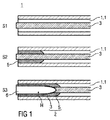
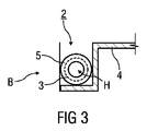
図1は、構造コンポーネント2を製造する装置1の、特に長手方向断面である断面表現を模式的に示す。図2は、構造コンポーネント2の長手方向断面を模式的に示す。図3は、構造コンポーネント2の短手方向断面を示す。構造コンポーネントは、有機シート4に接続されてコンポーネントBを形成する。有機シート4は、熱可塑性プラスチック材料のシート状の半完成品であって、その中には、ガラス、カーボン及び/若しくはアラミド繊維又はこれらの混合形態の織布が、当該熱可塑性プラスチック材料によって当該繊維が完全にぬらされるように導入されている。したがって、有機シート4は、連続した繊維強化熱可塑性プラスチックシートである。
FIG. 1 schematically shows a cross-sectional representation, in particular a longitudinal cross-section, of an
図1は、第1ステップS1、第2ステップS2及び第3ステップS3における装置1を(上から下への順で)例示する。
FIG. 1 illustrates the
本例示的実施形態では、装置1は鋳型1.1を含む。鋳型1.1は、熱成形鋳型及び射出鋳型を含む組み合わせ鋳型として形成されるのが好ましい。例えば、鋳型1.1は、第1鋳型体及び第2鋳型体を含む二部品の空洞形成複合体として形成される。この場合、2つの鋳型体の一方は、製造される構造コンポーネント2の凸状輪郭としての成形外形を有し、当該鋳型体の他方は、それに適切に対応する凹みを有する。凸状輪郭と凹みとが鋳型1.1の空洞を形成する。
In the present exemplary embodiment, the
鋳型1.1は、金属又は合金から形成されるのが好ましい。代替的に、鋳型1.1はセラミック又はプラスチックから形成される。鋳型1.1には、これを目的として、少なくとも当該空洞の領域内に金属被覆が設けられる。 The mold 1.1 is preferably formed from a metal or alloy. Alternatively, the mold 1.1 is formed from ceramic or plastic. For this purpose, the mold 1.1 is provided with a metal coating at least in the area of the cavity.
第1ステップS1において、織布管3が鋳型1.1の凸状輪郭の中に配置される。その後、鋳型1.1が閉じられる。鋳型1.1を閉じることは、この場合、手動で行われ又は好ましくは自動で行われる。
In the first step S1, the
第2ステップS2において、例えば溶融物5の形態にある液体プラスチックが、閉じられた鋳型1.1に配列された織布管3の中に射出される。これを目的として、装置1は、射出機(これ以上は特定的に表現しない)を含む。これは、手動により作動可能であり又は自動で動作する。
In a second step S2, liquid plastic, for example in the form of a
溶融物5は、例えば液体プラスチックであり、例えば100℃から200℃までのようなその融点を適切に上回る温度にある。これに対して特に適切なのは、単相かつ非水溶性の、例えばポリアミド、ポリオレフィン、ポリプロピレンのような熱可塑性プラスチック、又は、例えばポリウレタンのような熱硬化性樹脂である。
The
第3ステップS3において、例えば水のような流体6が、適切に低い温度及び適切に高い圧力において織布管3の中に導入される。その結果、すでに射出された溶融物5は、織布管3の外壁及び/又は内壁において織布管3上に及び/又は織布管3の中に、好ましくは均一に分散する。空洞Hを進展させるべく織布管3の開口端の中へ流体6を導入した後、織布管3の繊維が冷却された溶融物5の中に埋め込まれる。これにより、連続した繊維強化熱可塑性プラスチック構造コンポーネント2が製造される。これは、鋳型1.1の凸状輪郭に沿って中空体外形を備える。
In a third step S3, a
図1A及び1Bは、支持要素Sを使用して空洞Hを進展させる代替的な実施形態を示す。図1Aに係る支持要素Sは、例えば風船のような膨張可能被覆要素Eとして形成される。 FIGS. 1A and 1B show an alternative embodiment in which the support element S is used to advance the cavity H. FIG. The support element S according to FIG. 1A is formed as an inflatable covering element E, for example a balloon.
被覆要素Eが、すでに溶融物5によって囲まれた織布管3の開口端の中に導入されて、所定圧力下で、例えば空気、水又は気体のような流体6によって膨張される。その結果、空洞Hが、長手方向に延びる織布管3において進展する。溶融物5が、埋め込まれた織布管3とともに冷却された後、被覆要素Eは、除去することができるか又は、残しておくことが適切であれば、例えば、中空の構造コンポーネント2の内壁を形成する。
The covering element E is introduced into the open end of the woven
図1Bでは、例えば発泡体材料のような支持材料Mを、代替的支持要素Sとして織布管3の開口端の中に導入することができる。
In FIG. 1B, a support material M, for example a foam material, can be introduced into the open end of the woven
さらなるステップ(これ以上は特定的に表現しない)において、有機シート4が成形され、有機シート4の表面には、リブ構造物であることが好ましい強化構造物が裏鋳込みされる。リブ構造物は、有機シート4と同じ熱可塑性プラスチック材料から形成されるのが好ましい。したがって、統合されひいては一体化されたコンポーネントが、有機シート4及びリブ構造物から形成される。
In a further step (not specifically described above), an
有機シート4を構造コンポーネント2に結合することは、有機シート4の熱可塑性プラスチックマトリクス、及び/又は構造コンポーネント2の有機シート4に面する熱可塑性強化表面によって生じるのが好ましい。熱可塑性プラスチックマトリクスが適切に加熱される結果、構造コンポーネント2は、有機シート4と物質結合により接続されるようになる。すなわち、構造コンポーネント2と有機シート4との間に表面の溶融が生じる。
Combining the
閉じた中空の外形により、構造コンポーネント2は比較的高いねじり剛性を有する。したがって、構造コンポーネント2は、開いた外形を有する構造コンポーネント2と比べ、軽量化され、かつ、特に曲げの点で剛性となる。したがって、例えば、構造コンポーネント2は車両座席7のバックレスト後壁の製造に適する。
Due to the closed hollow profile, the
図4は、例として車両乗員8が配置された車両座席7の斜視図を示す。
FIG. 4 shows a perspective view of a
例えば、車両座席7のバックレスト後壁は、構造コンポーネント2及び有機シート4を使用して製造することができる。ヘッドレストスリーブ、ベルト偏向器、及び/又はベルト巻き取り装置を、有機シート4の鋳込みリブ構造物に形成することができる。
For example, the backrest rear wall of the
代替的に又は追加的に、構造コンポーネント2を、トリム溝として知られる車両座席カバーに配列された溝9に配列することができる。
Alternatively or additionally, the
1 装置
1.1 鋳型
2 構造コンポーネント
3 織布管
4 有機シート
5 溶融物
6 流体
7 車両座席
8 車両乗員
9 溝
B コンポーネント
E 被覆要素
H 空洞
M 支持材料
S 支持要素
S1 第1ステップ
S2 第2ステップ
S3 第3ステップ
DESCRIPTION OF
B component E covering element H cavity M support material S support element S1 first step S2 second step S3 third step
Claims (6)
・第1ステップ(S1)において、織布管(3)が鋳型(1.1)の輪郭の中に配置されてその後前記鋳型(1.1)が閉じられ、
・第2ステップ(S2)において、溶融物(5)であるプラスチックが、閉じられた前記鋳型(1.1)内に配列された前記織布管(3)の中に射出され、
・第3ステップ(S3)において、流体(6)及び/又は支持要素(S)が前記織布管(3)の中に導入されて前記織布管(3)の中に空洞(H)が形成されかつ前記織布管(3)が膨張し、前記溶融物(5)である前記プラスチックが冷却した後に前記プラスチックは、前記織布管(3)の埋め込まれた繊維と一緒に中空の構造コンポーネント(2)を形成し、
・有機シート(4)が成形されかつプラスチックにより裏鋳込みされ、
・成形されかつ裏鋳込みされた前記有機シート(4)が前記構造コンポーネント(2)に物質結合により接続されて前記コンポーネント(B)を形成する方法。 A method for producing a component (B) formed from at least a structural component (2) and an organic sheet (4),
In the first step (S1), the woven tube (3) is placed in the contour of the mold (1.1) and then the mold (1.1) is closed,
In the second step (S2), the plastic that is the melt (5) is injected into the woven tube (3) arranged in the closed mold (1.1),
In a third step (S3), the fluid (6) and / or the support element (S) are introduced into the woven tube (3) and a cavity (H) is formed in the woven tube (3). After the woven tube (3) has been formed and the melt, which is the melt (5), has cooled, the plastic is hollow with the fibers embedded in the woven tube (3). Forming component (2),
The organic sheet (4) is molded and back cast with plastic,
A method in which the molded and back-cast organic sheet (4) is connected to the structural component (2) by material bonding to form the component (B).
A continuous fiber reinforced structural component (2) having a hollow body profile is formed after the melt (5) having at least a certain area embedded in the woven tube (3) is cooled. The method according to any one of 1 to 5.
Applications Claiming Priority (5)
| Application Number | Priority Date | Filing Date | Title |
|---|---|---|---|
| DE102012201043.2 | 2012-01-25 | ||
| DE102012201043 | 2012-01-25 | ||
| DE102012204036A DE102012204036A1 (en) | 2012-01-25 | 2012-03-14 | Method and device for producing a structural component |
| DE102012204036.6 | 2012-03-14 | ||
| PCT/EP2013/051456 WO2013110770A1 (en) | 2012-01-25 | 2013-01-25 | Method for producing a component and component |
Publications (3)
| Publication Number | Publication Date |
|---|---|
| JP2015509867A JP2015509867A (en) | 2015-04-02 |
| JP2015509867A5 JP2015509867A5 (en) | 2016-05-12 |
| JP5970558B2 true JP5970558B2 (en) | 2016-08-17 |
Family
ID=48742439
Family Applications (1)
| Application Number | Title | Priority Date | Filing Date |
|---|---|---|---|
| JP2014551653A Expired - Fee Related JP5970558B2 (en) | 2012-01-25 | 2013-01-25 | Method for manufacturing components |
Country Status (7)
| Country | Link |
|---|---|
| US (1) | US10005379B2 (en) |
| EP (1) | EP2807016B8 (en) |
| JP (1) | JP5970558B2 (en) |
| KR (1) | KR101749484B1 (en) |
| CN (1) | CN104066568B (en) |
| DE (1) | DE102012204036A1 (en) |
| WO (1) | WO2013110770A1 (en) |
Families Citing this family (12)
| Publication number | Priority date | Publication date | Assignee | Title |
|---|---|---|---|---|
| US9676311B2 (en) * | 2012-05-29 | 2017-06-13 | Faurecia Automotive Seating, Llc | Vehicle seat assembly with composite frame |
| JP6004863B2 (en) * | 2012-09-24 | 2016-10-12 | テイ・エス テック株式会社 | Seat frame |
| DE102013215375A1 (en) * | 2013-08-05 | 2015-02-05 | Bayerische Motoren Werke Aktiengesellschaft | Method for the production of an at least partially hollow structural component of a vehicle |
| DE102013220990A1 (en) * | 2013-10-16 | 2015-04-30 | Bayerische Motoren Werke Aktiengesellschaft | Blow hose for internal pressure injection molding |
| DE102013221008A1 (en) * | 2013-10-16 | 2015-04-16 | Bayerische Motoren Werke Aktiengesellschaft | Method for producing a plastic molding and device for producing a plastic molding |
| DE102013021876A1 (en) * | 2013-12-21 | 2015-06-25 | Audi Ag | Method and device for producing laminar composite structures |
| DE202014004095U1 (en) * | 2014-05-15 | 2015-08-20 | GM Global Technology Operations LLC (n. d. Ges. d. Staates Delaware) | Cross member for a vehicle seat and vehicle seat with the crossbar |
| US20180339622A1 (en) * | 2015-05-06 | 2018-11-29 | Schukra Gerätebau Gmbh | System and method of controlling fibers in a mold |
| DE102016117903A1 (en) * | 2016-09-22 | 2018-03-22 | Dr. Ing. H.C. F. Porsche Aktiengesellschaft | Body part assembly for a motor vehicle and method of making such a body part assembly |
| DE102017118826A1 (en) * | 2017-08-17 | 2019-02-21 | Friedrich Westphal | Process for producing a component from a plastic preform formed as a hollow body |
| DE102018212442A1 (en) * | 2018-07-25 | 2020-01-30 | Brose Fahrzeugteile Gmbh & Co. Kommanditgesellschaft, Coburg | Vehicle seat frame with a tubular element made of a fiber composite material |
| DE102019209489B4 (en) | 2018-12-18 | 2021-07-08 | Continental Teves Ag & Co. Ohg | Injection molding device, projectile injection method and a hollow-shaped plastic object produced according to the method |
Family Cites Families (9)
| Publication number | Priority date | Publication date | Assignee | Title |
|---|---|---|---|---|
| JP2745853B2 (en) * | 1991-02-13 | 1998-04-28 | トヨタ自動車株式会社 | Method for manufacturing hollow FRP molded article |
| JPH0818346B2 (en) * | 1991-10-19 | 1996-02-28 | 住友ゴム工業株式会社 | Fiber-reinforced resin product and manufacturing method thereof |
| DE19747021B4 (en) | 1997-10-24 | 2007-12-20 | Vereinigung zur Förderung des Instituts für Kunststoffverarbeitung in Industrie und Handwerk an der Rhein.-Westf. Technischen Hochschule Aachen eV | Method for injection molding continuous fiber reinforced hollow body |
| US6764638B1 (en) * | 1999-06-22 | 2004-07-20 | Exatec, L.L.C. | Process for manufacturing a molding plastic window for an automotive vehicle and window produced thereby |
| JP2001301532A (en) * | 2000-04-21 | 2001-10-31 | Kasai Kogyo Co Ltd | Interior part for automobile and its manufacturing method |
| US20090011213A1 (en) * | 2007-07-03 | 2009-01-08 | General Electric Company | Recyclable Multilayer Thermoplastic Films and Methods of Making |
| DE102007036660A1 (en) * | 2007-08-03 | 2009-02-05 | Kraussmaffei Technologies Gmbh | Method and device for producing a reinforced composite product |
| DE102008046602A1 (en) * | 2008-09-10 | 2010-03-11 | Daimler Ag | Method for manufacturing fiber-reinforced injection molding component, involves inserting fiber-reinforced hose into spraying casting tool, and injecting casting material into spraying casting tool |
| DE102011053100A1 (en) * | 2011-08-30 | 2013-02-28 | Rehau Ag + Co | Two-wheeler frame, two-wheeler and method of manufacturing a bicycle frame |
-
2012
- 2012-03-14 DE DE102012204036A patent/DE102012204036A1/en not_active Withdrawn
-
2013
- 2013-01-25 WO PCT/EP2013/051456 patent/WO2013110770A1/en active Application Filing
- 2013-01-25 CN CN201380006274.5A patent/CN104066568B/en not_active Expired - Fee Related
- 2013-01-25 JP JP2014551653A patent/JP5970558B2/en not_active Expired - Fee Related
- 2013-01-25 EP EP13702613.4A patent/EP2807016B8/en not_active Not-in-force
- 2013-01-25 US US14/374,450 patent/US10005379B2/en active Active
- 2013-01-25 KR KR1020147023730A patent/KR101749484B1/en active IP Right Grant
Also Published As
| Publication number | Publication date |
|---|---|
| JP2015509867A (en) | 2015-04-02 |
| US10005379B2 (en) | 2018-06-26 |
| EP2807016B1 (en) | 2017-06-28 |
| CN104066568A (en) | 2014-09-24 |
| US20140377498A1 (en) | 2014-12-25 |
| EP2807016B8 (en) | 2017-08-16 |
| CN104066568B (en) | 2016-12-07 |
| DE102012204036A1 (en) | 2013-07-25 |
| KR101749484B1 (en) | 2017-06-21 |
| WO2013110770A1 (en) | 2013-08-01 |
| EP2807016A1 (en) | 2014-12-03 |
| KR20140124798A (en) | 2014-10-27 |
Similar Documents
| Publication | Publication Date | Title |
|---|---|---|
| JP5970558B2 (en) | Method for manufacturing components | |
| JP2015509867A5 (en) | ||
| US20230192197A1 (en) | Method of making a laminate, an energy absorbing device, an energy absorbing device composition, and a forming tool | |
| JP6150807B2 (en) | Working fluid tank for automobile | |
| ES2622417T3 (en) | Method for manufacturing a hollow composite structure | |
| US20130052392A1 (en) | Composite component for a vehicle | |
| JP5891304B2 (en) | Joint structure for automobile and manufacturing method thereof | |
| US9914490B2 (en) | Frame structure with at least one console for connecting further components, method for producing and motor vehicle body | |
| JP5820936B2 (en) | Method for manufacturing a structural component and apparatus for carrying out the method | |
| DE102011111744B4 (en) | Control box module and manufacturing process | |
| KR20130028775A (en) | Fuel tank of plastic and method for the production thereof | |
| US11214025B2 (en) | Fibre-reinforced components | |
| JP2017537822A (en) | Fiber reinforced structure | |
| JP2015502873A5 (en) | ||
| CN105083018A (en) | Hybrid composite instrument panel | |
| CN101342787A (en) | Compound material special piece molding method and molding central spindle | |
| CN104626603A (en) | Manufacturing method of carbon fiber frame and molding mold | |
| CN100491152C (en) | Control panel and method for the production thereof | |
| JP2009143178A (en) | Method for molding fiber-reinforced resin hollow component | |
| US11548243B2 (en) | Method for producing a fiber-reinforced structural hollow component | |
| CN105083019A (en) | Modular composite intrument panel | |
| SE509503C2 (en) | Arrangement, procedure and hollow body when forming plastic parts | |
| JP6582429B2 (en) | Sandwich molded body, molding method thereof and molding apparatus | |
| JP2001524899A (en) | Arrangement and method for forming a reinforced thermoplastic load bearing member, and the load bearing member | |
| EP3612366B1 (en) | Hollow part manufacture |
Legal Events
| Date | Code | Title | Description |
|---|---|---|---|
| A131 | Notification of reasons for refusal |
Free format text: JAPANESE INTERMEDIATE CODE: A131 Effective date: 20150526 |
|
| A521 | Written amendment |
Free format text: JAPANESE INTERMEDIATE CODE: A523 Effective date: 20150818 |
|
| A131 | Notification of reasons for refusal |
Free format text: JAPANESE INTERMEDIATE CODE: A131 Effective date: 20160202 |
|
| A524 | Written submission of copy of amendment under section 19 (pct) |
Free format text: JAPANESE INTERMEDIATE CODE: A524 Effective date: 20160316 |
|
| TRDD | Decision of grant or rejection written | ||
| A01 | Written decision to grant a patent or to grant a registration (utility model) |
Free format text: JAPANESE INTERMEDIATE CODE: A01 Effective date: 20160614 |
|
| A61 | First payment of annual fees (during grant procedure) |
Free format text: JAPANESE INTERMEDIATE CODE: A61 Effective date: 20160711 |
|
| R150 | Certificate of patent or registration of utility model |
Ref document number: 5970558 Country of ref document: JP Free format text: JAPANESE INTERMEDIATE CODE: R150 |
|
| LAPS | Cancellation because of no payment of annual fees |