JP5970054B2 - Endoscope system, light source device for endoscope system, and method for operating endoscope system - Google Patents
Endoscope system, light source device for endoscope system, and method for operating endoscope system Download PDFInfo
- Publication number
- JP5970054B2 JP5970054B2 JP2014253817A JP2014253817A JP5970054B2 JP 5970054 B2 JP5970054 B2 JP 5970054B2 JP 2014253817 A JP2014253817 A JP 2014253817A JP 2014253817 A JP2014253817 A JP 2014253817A JP 5970054 B2 JP5970054 B2 JP 5970054B2
- Authority
- JP
- Japan
- Prior art keywords
- light
- image
- special
- endoscope system
- light quantity
- Prior art date
- Legal status (The legal status is an assumption and is not a legal conclusion. Google has not performed a legal analysis and makes no representation as to the accuracy of the status listed.)
- Active
Links
- 238000000034 method Methods 0.000 title claims description 33
- 210000004204 blood vessel Anatomy 0.000 claims description 60
- 238000012545 processing Methods 0.000 claims description 32
- 238000003384 imaging method Methods 0.000 claims description 30
- 239000004065 semiconductor Substances 0.000 claims description 27
- 239000002131 composite material Substances 0.000 claims description 20
- 238000005286 illumination Methods 0.000 claims description 10
- 239000000203 mixture Substances 0.000 claims description 8
- 230000001678 irradiating effect Effects 0.000 claims description 3
- 239000008280 blood Substances 0.000 claims 1
- 210000004369 blood Anatomy 0.000 claims 1
- 238000012937 correction Methods 0.000 description 13
- 239000010410 layer Substances 0.000 description 9
- 238000003745 diagnosis Methods 0.000 description 8
- 210000004877 mucosa Anatomy 0.000 description 8
- 239000002344 surface layer Substances 0.000 description 8
- 238000000605 extraction Methods 0.000 description 7
- 230000003902 lesion Effects 0.000 description 6
- 238000005452 bending Methods 0.000 description 4
- 238000001914 filtration Methods 0.000 description 4
- 210000004088 microvessel Anatomy 0.000 description 4
- 230000003595 spectral effect Effects 0.000 description 4
- 238000002834 transmittance Methods 0.000 description 4
- 206010028980 Neoplasm Diseases 0.000 description 3
- 230000015572 biosynthetic process Effects 0.000 description 3
- 201000011510 cancer Diseases 0.000 description 3
- 238000006243 chemical reaction Methods 0.000 description 3
- 239000013307 optical fiber Substances 0.000 description 3
- 238000003786 synthesis reaction Methods 0.000 description 3
- 238000010521 absorption reaction Methods 0.000 description 2
- 239000011159 matrix material Substances 0.000 description 2
- 238000005259 measurement Methods 0.000 description 2
- 210000004400 mucous membrane Anatomy 0.000 description 2
- 230000004043 responsiveness Effects 0.000 description 2
- 238000004088 simulation Methods 0.000 description 2
- 210000001519 tissue Anatomy 0.000 description 2
- 238000009825 accumulation Methods 0.000 description 1
- 239000003086 colorant Substances 0.000 description 1
- 238000004891 communication Methods 0.000 description 1
- 230000000295 complement effect Effects 0.000 description 1
- 230000003247 decreasing effect Effects 0.000 description 1
- 230000000694 effects Effects 0.000 description 1
- 239000000835 fiber Substances 0.000 description 1
- 238000003702 image correction Methods 0.000 description 1
- 238000004519 manufacturing process Methods 0.000 description 1
- 229910044991 metal oxide Inorganic materials 0.000 description 1
- 150000004706 metal oxides Chemical class 0.000 description 1
- 238000011017 operating method Methods 0.000 description 1
- 230000003287 optical effect Effects 0.000 description 1
- 238000012546 transfer Methods 0.000 description 1
- XLYOFNOQVPJJNP-UHFFFAOYSA-N water Substances O XLYOFNOQVPJJNP-UHFFFAOYSA-N 0.000 description 1
Images


Landscapes
- Instruments For Viewing The Inside Of Hollow Bodies (AREA)
- Endoscopes (AREA)
- Closed-Circuit Television Systems (AREA)
Description
本発明は、RGBのLEDなど複数の半導体光源を用いて被検体内の観察画像を取得する内視鏡システム、内視鏡システムの光源装置、及び内視鏡システムの作動方法に関する。 The present invention relates to an endoscope system that acquires an observation image in a subject using a plurality of semiconductor light sources such as RGB LEDs, a light source device for the endoscope system, and a method for operating the endoscope system.
近年の医療用内視鏡分野においては、特定波長の狭帯域光を被検体内に照射することで、白色光などの広帯域光では観察し難かった表層血管や表層微細構造などを明瞭化することができる狭帯域光観察が行われている。表層血管や表層微細構造の形状やパターンは、ガンなどの病変部の識別や病変部の深達度の推定に大きな手掛かりとなるものであるため、それら表層血管等の明瞭化は診断能を飛躍的に向上させることができる。 In the field of medical endoscopes in recent years, by irradiating a subject with narrowband light of a specific wavelength, the surface blood vessels and surface microstructures that were difficult to observe with broadband light such as white light are clarified. Narrow-band light observation is possible. The shape and pattern of the superficial blood vessels and superficial microstructures are important clues for identifying lesions such as cancer and estimating the depth of the lesions. Can be improved.
例えば、特許文献1に示す狭帯域光観察においては、中心波長415nmの青色狭帯域光と、中心波長540nmの緑色狭帯域光とが交互に被検体に照射され、各色の狭帯域光が照射される毎に撮像が行われる。そして、青色狭帯域光の撮像により得られる青色狭帯域画像はモニタのBチャンネルとGチャンネルに割り当てる一方、緑色狭帯域光の撮像により得られる緑色狭帯域画像はモニタのRチャンネルに割り当てられる。これにより、青色狭帯域光に吸収特性を有する表層血管と緑色狭帯域光に吸収特性を有する中深層血管の両方が強調された疑似カラーの狭帯域光画像がモニタに表示される。 For example, in narrowband light observation shown in Patent Document 1, blue narrowband light having a center wavelength of 415 nm and green narrowband light having a center wavelength of 540 nm are alternately irradiated on the subject, and narrowband light of each color is irradiated. Imaging is performed every time. A blue narrowband image obtained by imaging blue narrowband light is assigned to the B channel and G channel of the monitor, while a green narrowband image obtained by imaging green narrowband light is assigned to the R channel of the monitor. As a result, a pseudo-color narrowband light image in which both the surface blood vessel having the absorption characteristic for the blue narrowband light and the middle deep blood vessel having the absorption characteristic for the green narrowband light are emphasized is displayed on the monitor.
しかしながら、狭帯域光観察で使用する狭帯域光は波長帯域が制限されているため、どうしても光量が不足してしまう。この光量不足は、内視鏡照明部と観察エリアとの距離が離れる遠景状態において顕著になる。そこで、特許文献2の内視鏡においては、遠景状態での観察にも確実に診断を行うことができるように、モニタには、狭帯域光画像に加えて、波長帯域が広帯域の白色光の撮像により得られる通常光画像を並列表示することが行われている。 However, since the wavelength band of narrowband light used in narrowband light observation is limited, the amount of light is inevitably insufficient. This shortage of light becomes noticeable in a distant view where the distance between the endoscope illumination unit and the observation area is large. Therefore, in the endoscope of Patent Document 2, in order to be able to make a diagnosis reliably even in observation in a distant view state, in addition to the narrow band light image, the monitor includes white light having a wide wavelength band. A normal light image obtained by imaging is displayed in parallel.
しかしながら、特許文献2のように、モニタに通常光画像と狭帯域光画像とを並列表示した場合には、それら2種類の画像を見比べる必要があるため、診断を行う術者に負担を強いることとなる。したがって、術者が1つの画像だけで診断を行うことができるように、病変部の診断に大きく貢献する表層血管や表層微細構造が明瞭化され、且つ遠景状態のような光量が不足する状況下においても十分に明るさが確保された画像を取得することができる内視鏡システムが求められている。 However, when the normal light image and the narrowband light image are displayed in parallel on the monitor as in Patent Document 2, it is necessary to compare these two types of images, which imposes a burden on the surgeon performing the diagnosis. It becomes. Therefore, under conditions where the surface blood vessels and the surface microstructure that greatly contribute to the diagnosis of the lesion are clarified and the light quantity is insufficient such as in a distant state so that the surgeon can make a diagnosis with only one image. There is also a need for an endoscope system that can acquire an image with sufficient brightness.
本発明は、表層血管や表層微細構造などの観察部位が明瞭化された画像を取得することができる内視鏡システム、内視鏡システムの光源装置、及び内視鏡システムの作動方法を提供することを目的とする。 The present invention provides an endoscope system, a light source device for an endoscope system, and a method for operating the endoscope system that can acquire an image in which an observation site such as a superficial blood vessel and a superficial fine structure is clarified. For the purpose.
本発明の内視鏡システムは、青色帯域のB光を発する青色半導体光源と、緑色帯域のG光を発する緑色半導体光源と、赤色帯域のR光を発する赤色半導体光源と、B光、G光、R光が照射された被検体内を撮像することによって、明るさが互いに異なる通常光画像と特殊光画像とを取得する画像取得手段と、通常光画像を取得する際に照射するB光、G光、R光の第1光量値と、この第1光量値と異なる光量値であって特殊光画像を取得する際に照射するB光、G光、R光の第2光量値との切り替え制御を、各半導体光源に対して行う光量制御手段とを備え、光量制御手段は、表層血管や表層微細構造を明瞭化した特殊光画像を取得するときには、B光、G光、R光の第2光量値を、B光の光量>G光の光量>R光の光量の関係にし、中層血管や中深層の構造を明瞭化した特殊光画像を取得するときには、B光、G光、R光の第2光量値を、G光の光量またはR光の光量をB光の光量よりも大きい関係にすることを特徴とする。 An endoscope system according to the present invention includes a blue semiconductor light source that emits blue band B light, a green semiconductor light source that emits green band G light, a red semiconductor light source that emits red band R light, and B light and G light. Image acquisition means for acquiring a normal light image and a special light image with different brightness by imaging the inside of the subject irradiated with the R light, and B light irradiated when acquiring the normal light image, Switching between the first light amount value of G light and R light and the second light amount value of B light, G light, and R light that is different from the first light amount value and is emitted when acquiring a special light image A light amount control unit that performs control on each semiconductor light source, and the light amount control unit obtains a special light image that clarifies the surface blood vessels and the surface fine structure, and outputs the first light of B light, G light, and R light. Two light quantity values are set such that B light quantity> G light quantity> R light quantity. When acquiring a special light image with a clear structure, the second light quantity value of B light, G light, and R light should be set so that the G light quantity or R light quantity is greater than the B light quantity. It is characterized by.
画像取得手段は、B光、G光、R光の第2光量値を、B光の光量>G光の光量>R光の光量の関係にしたときには、カラー撮像素子を用いた撮像により得られた青色画像信号、緑色画像信号、赤色画像信号のうち、青色画像信号を特殊光画像のB画像及びG画像に、緑色画像信号を特殊光画像のR画像に割り付けることが好ましい。 The image acquisition means is obtained by imaging using a color imaging device when the second light quantity value of B light, G light, and R light has a relationship of light quantity of B light> light quantity of G light> light quantity of R light. Of the blue image signal, green image signal, and red image signal, the blue image signal is preferably assigned to the B image and the G image of the special light image, and the green image signal is preferably assigned to the R image of the special light image.
画像取得手段は、B光、G光、R光の第2光量値を、B光の光量>G光の光量>R光の光量の関係にしたときには、高周波数帯域を透過させるバンドパスフィルタを特殊光画像に施すことによって、粘膜中深層の血管を除去して、粘膜表層の微細血管を抽出することが好ましい。 When the second light quantity value of the B light, the G light, and the R light has a relationship of the light quantity of the B light> the light quantity of the G light> the light quantity of the R light, the image acquisition means includes a band pass filter that transmits the high frequency band. It is preferable to extract the fine blood vessels in the mucosal surface layer by removing the blood vessels in the deep mucosa layer by applying to the special light image.
B光、G光、R光の第2光量値を、G光の光量またはR光の光量をB光の光量よりも大きい関係にしたときには、カラー撮像素子を用いた撮像により得られた青色画像信号、緑色画像信号、赤色画像信号のうち、緑色画像信号を特殊光画像のB画像及びG画像に、赤色画像信号を特殊光画像のR画像に割り付けることが好ましい。 When the second light quantity value of B light, G light, and R light is related to the light quantity of G light or the light quantity of R light larger than the light quantity of B light, a blue image obtained by imaging using a color image sensor Of the signal, the green image signal, and the red image signal, the green image signal is preferably assigned to the B image and the G image of the special light image, and the red image signal is preferably assigned to the R image of the special light image.
画像取得手段は、B光、G光、R光の第2光量値を、G光の光量またはR光の光量をB光の光量よりも大きい関係にしたときには、低周波数帯域を透過させるバンドパスフィルタを特殊光画像に施すことによって、表層微細血管を除去して、粘膜中深層の血管を抽出することが好ましい。 The image acquisition means transmits the low frequency band when the second light quantity value of the B light, the G light, and the R light is set so that the G light quantity or the R light quantity is greater than the B light quantity. By applying a filter to the special light image, it is preferable to remove superficial fine blood vessels and extract blood vessels in the middle mucosa.
画像取得手段は、ローパスフィルタ、バンドパスフィルタ、ハイパスフィルタの組み合わせたものを特殊光画像に施すことによって、観察対象の血管を強調する一方、それ以外の血管を抑制することが好ましい。 It is preferable that the image acquisition unit emphasizes the blood vessel to be observed while applying a combination of a low-pass filter, a band-pass filter, and a high-pass filter to the special light image, while suppressing other blood vessels.
特殊光画像に所定の処理を施す画像処理部と、所定の処理が施された特殊光画像と通常光画像を合成して合成画像を生成する画像合成部とを有することが好ましい。所定の処理は所定の色成分を抽出する処理であることが好ましい。所定の処理は所定のコントラストを有する部分を抽出する処理であることが好ましい。所定の処理は所定の構造を有する部分を抽出する処理であることが好ましい。画像処理部は、所定の処理が施された特殊光画像に対して、更に、血管の密集部分を抽出する処理を施すことが好ましい。 It is preferable to include an image processing unit that performs predetermined processing on the special light image, and an image combining unit that combines the special light image that has been subjected to the predetermined processing and the normal light image to generate a combined image. The predetermined process is preferably a process for extracting a predetermined color component. The predetermined process is preferably a process for extracting a portion having a predetermined contrast. The predetermined process is preferably a process for extracting a portion having a predetermined structure. It is preferable that the image processing unit further performs a process of extracting dense blood vessels on the special light image that has been subjected to the predetermined process.
本発明は、明るさが互いに異なる通常光画像と特殊光画像とを取得するために、青色帯域のB光、緑色帯域のG光、赤色帯域のR光を照射して被検体内を撮像する内視鏡装置に対して、被検体内を照明する照明光を供給する内視鏡システムの光源装置において、B光を発する青色半導体光源と、G光を発する緑色半導体光源と、R光を発する赤色半導体光源と、通常光画像を取得する際に照射するB光、G光、R光の第1光量値と、この第1光量値と異なる光量値であって特殊光画像を取得する際に照射するB光、G光、R光の第2光量値との切り替え制御を、各半導体光源に対して行う光量制御手段とを備え、光量制御手段は、表層血管や表層微細構造を明瞭化した特殊光画像を取得するときには、B光、G光、R光の第2光量値を、B光の光量>G光の光量>R光の光量の関係にし、中層血管や中深層の構造を明瞭化した特殊光画像を取得するときには、B光、G光、R光の第2光量値を、G光の光量またはR光の光量をB光の光量よりも大きい関係にすることを特徴とする。 In order to acquire a normal light image and a special light image having different brightness, the present invention images the inside of a subject by irradiating blue band B light, green band G light, and red band R light. In a light source device of an endoscope system that supplies illumination light for illuminating the inside of a subject to an endoscope apparatus, a blue semiconductor light source that emits B light, a green semiconductor light source that emits G light, and R light are emitted. When acquiring a special light image with a red semiconductor light source, a first light amount value of B light, G light, and R light irradiated when acquiring a normal light image, and a light amount value different from the first light amount value A light amount control unit that performs switching control with respect to the second light amount values of the irradiated B light, G light, and R light to each semiconductor light source, and the light amount control unit clarifies the surface blood vessels and the surface layer microstructure. When acquiring a special light image, use the second light quantity value of B light, G light, and R light as the light quantity of B light. When acquiring a special light image with the structure of the middle-layer blood vessels and middle-layers clarified with the relationship of> light amount of G light> light amount of R light, the second light amount value of B light, G light, and R light is set to G light. The amount of light or the amount of R light is larger than the amount of B light.
本発明は、青色半導体光源が青色帯域のB光を発し、緑色半導体光源が緑色帯域のG光を発し、赤色半導体光源が赤色帯域のR光を発するステップと、画像取得手段が、B光、G光、R光が照射された被検体内を撮像することによって、明るさが互いに異なる通常光画像と特殊光画像とを取得するステップとを有する内視鏡システムの作動方法において、 光量制御手段が、通常光画像を取得する際に照射するB光、G光、R光の第1光量値と、この第1光量値と異なる光量値であって特殊光画像を取得する際に照射するB光、G光、R光の第2光量値との切り替え制御を、各半導体光源に対して行うステップであり、光量制御手段が、表層血管や表層微細構造を明瞭化した特殊光画像を取得するときには、B光、G光、R光の第2光量値を、B光の光量>G光の光量>R光の光量の関係にし、中層血管や中深層の構造を明瞭化した特殊光画像を取得するときには、B光、G光、R光の第2光量値を、G光の光量またはR光の光量をB光の光量よりも大きい関係にするステップを有することを特徴とする。 The present invention includes a step in which a blue semiconductor light source emits blue band B light, a green semiconductor light source emits green band G light, a red semiconductor light source emits red band R light, and an image acquisition means includes B light, In an operating method of an endoscope system, the method comprising: obtaining a normal light image and a special light image having different brightness by imaging the inside of a subject irradiated with G light and R light. However, the B light, the G light, and the R light that are irradiated when acquiring the normal light image, and the B light that is irradiated when acquiring the special light image having a light amount value different from the first light amount value. This is a step of performing switching control with respect to the second light amount values of light, G light, and R light for each semiconductor light source, and the light amount control means acquires a special light image that clarifies the surface blood vessels and the surface layer microstructure. Sometimes the second light quantity value of B light, G light, and R light is When acquiring a special light image with the structure of the middle-layer blood vessels and middle-layers clarified with the relationship of> light amount of G light> light amount of R light, the second light amount value of B light, G light, and R light is set to G light. And a step of making the amount of light of R or the amount of light of R light larger than the amount of light of B light.
本発明によれば、B光の光量>G光の光量>R光の光量の条件下で取得した特殊光画像は、表層血管や表層微細構造が明瞭化された画像となっている。G光の光量またはR光の光量をB光の光量よりも大きくした状態で取得した特殊光画像は、表層血管等よりも中深層血管や中深層の生体組織が明瞭化された画像となっている。 According to the present invention, the special light image obtained under the condition of the light amount of B light> the light amount of G light> the light amount of R light is an image in which the surface blood vessels and the surface microstructure are clarified. A special light image acquired in a state where the light amount of G light or the light amount of R light is larger than the light amount of B light is an image in which the mid-deep blood vessels and the medium tissues of the mid-deep layer are clarified rather than the surface blood vessels. Yes.
図1及び2に示すように、内視鏡システム10は、被検体を照明する照明光を発生する光源装置11と、光源装置11からの照明光を被検体の観察領域に照射し、その反射光等を撮像する内視鏡装置12と、内視鏡装置12で得られた画像信号を画像処理するプロセッサ装置13と、画像処理によって得られた内視鏡画像等を表示する表示装置14と、キーボード等で構成される入力装置15とを備えている。
As shown in FIGS. 1 and 2, an
内視鏡システム10は、波長範囲が青色から赤色に及ぶ可視光の被検体像からなる通常光画像を表示装置14に表示する通常光観察モードと、通常光画像上に、観察対象の血管や構造が明瞭化された特殊光画像を合成した合成画像を表示装置14に表示する特殊光観察モードを備えている。通常光観察モードでは、1フレーム分の通常光画像を取得する期間(通常光画像取得フレーム)が予め設定されている。特殊光観察モードにおいても、通常光観察モードと同様に、1フレーム分の通常光画像を取得する期間(通常光画像取得フレーム)が予め設定されており、さらに、1フレーム分の特殊光画像を取得する期間(特殊光画像取得フレーム)も予め設定されている。これら観察モードは、内視鏡装置の切り替えスイッチ17や入力装置15から入力される指示に基づき、適宜切り替えられる。
The
光源装置11は、B−LED、G−LED、R−LEDの3つのLED(Light Emitting Diode)と、B光量制御部20b、G光量制御部20g、R光量制御部20rとを備えている。図3に示すように、B−LEDは波長域が青色帯域のB光を発し、G−LEDは波長域が緑色帯域のG光を発し、R−LEDは波長域が赤色帯域のR光を発する。これらB光、G光、R光は一定の範囲内で光量の増減が可能である。各LEDから発せられるB光、G光、R光は、集光レンズ(図示省略)を介してそれぞれ光ファイバ24b,24g,24rに入射する。
The
なお、LEDの代わりに、レーザ光源を使用してもよい。レーザ光源としては、例えば、ブロードエリア型のInGaN系レーザダイオードが使用でき、また、InGaNAs系レーザダイオードやGaNAs系レーザダイオード等を用いることが好ましい A laser light source may be used instead of the LED. As the laser light source, for example, a broad area type InGaN laser diode can be used, and an InGaNAs laser diode, a GaNAs laser diode, or the like is preferably used.
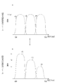
B光量制御部20b、G光量制御部20g、R光量制御部20rは、それぞれB−LEDの光量、G−LEDの光量、R−LEDの光量を制御する。各LEDに対する光量の制御は、設定されている観察モードによって異なる。通常光観察モードに設定されている場合には、図4に示すように、B光、G光、R光の光量がそれぞれ略同等となるように(B光の光量Lb=G光の光量Lg=R光の光量Lr)、B−LED、G−LED、R−LEDを制御する。
The B light
特殊光観察モードに設定されている場合には、図5に示すように、通常光画像取得フレームにおいては、B光、G光、R光の光量がそれぞれ略同等となるように(Lb=Lg=Lr)、B−LED、G−LED、R−LEDを制御する。一方、特殊光画像取得フレームにおいては、B光の光量Lb>G光の光量Lg>R光の光量Lrとなるように、B−LED、G−LED、R−LEDを制御する。特殊光観察モードでは、通常光画像取得フレームと特殊光画像取得フレームとが交互に切り替わるため、このフレームの切り替えに合わせて、各LEDの光量も上記のように切り替えられる。 When the special light observation mode is set, as shown in FIG. 5, in the normal light image acquisition frame, the light amounts of B light, G light, and R light are substantially equal to each other (Lb = Lg = Lr), B-LED, G-LED, R-LED are controlled. On the other hand, in the special light image acquisition frame, the B-LED, the G-LED, and the R-LED are controlled so that the B light amount Lb> the G light amount Lg> the R light amount Lr. In the special light observation mode, the normal light image acquisition frame and the special light image acquisition frame are alternately switched, so that the light amount of each LED is also switched as described above in accordance with the switching of the frame.
特殊光観察モードにおける通常光画像取得フレームと特殊光画像取得フレーム間の切り替えは、良好な動画性を確保する点から、極めて短時間の間に行われる。したがって、このフレームの切り替えに連動して光量調整を行う光源は、応答性がフレーム切替速度と同等またはそれ以上である必要がある。この応答性という点においては、半導体光源であるLEDは十分にその要求を満たしている。 Switching between the normal light image acquisition frame and the special light image acquisition frame in the special light observation mode is performed in a very short time from the viewpoint of securing good moving image properties. Therefore, a light source that adjusts the amount of light in conjunction with this frame switching needs to have a responsiveness equal to or higher than the frame switching speed. In terms of this responsiveness, the LED which is a semiconductor light source sufficiently satisfies the requirement.
図1及び図2に示すように、コンバイナ21は、各光ファイバ24b,24g,24rからのB光,G光,R光を合波させる。この合波で3色のB光,G光,R光が合波することによって、波長域が青色から緑色に及ぶ広帯域光が生成される。コンバイナ21から出た広帯域光は、分波器であるカプラ22によって2系統の光に分波される。分波された2系統の広帯域光は、ライトガイド28,29で伝送される。ライトガイド28,29は多数の光ファイバを束ねたバンドルファイバなどから構成される。なお、コンバイナ21及びカプラ22を用いずに、各LEDからの光を直接ライトガイド28,29に入れる構成としてもよい。
As shown in FIGS. 1 and 2, the
内視鏡装置12は電子内視鏡から構成され、内視鏡スコープ32と、ライトガイド28,29で伝送される2系統(2灯)の光を照射する照明部33と、被観察領域を撮像する1系統の撮像部34、内視鏡スコープ32の先端部の湾曲操作や観察のための操作を行う操作部35と、内視鏡スコープ32と光源装置11及びプロセッサ装置13とを着脱自在に接続するコネクタ部36を備えている。
The
内視鏡スコープ32には、操作部35側から順に、軟性部38、湾曲部39、スコープ先端部40が設けられている。軟性部38は、可撓性を有しているため、内視鏡スコープ挿入時には被検体内で屈曲自在にすることができる。湾曲部39は、操作部35に配置されたアングルノブ35aの回動操作により湾曲自在に構成されている。この湾曲部39は、被検体の部位等に応じて、任意の方向、任意の角度に湾曲させることができるため、スコープ先端部40を所望の観察部位に向けることができる。
The
スコープ先端部40には照明部33と撮像部34が設けられている。撮像部34は、スコープ先端部40の略中心位置に、被写体領域からの反射光等を撮像する1つの観察窓42を備えている。照明部33は、撮像部34の両脇に設けられた2つの照明窓43,44を備えており、各照明窓43,44は、広帯域光を被観察領域に向けて照射する。
The
観察窓42の奥には、被検体の被観察領域の像光を取り込むための対物レンズユニット(図示省略)等の光学系が設けられており、さらにその対物レンズユニットの奥には、被観察領域の像光を受光して被観察領域を撮像するCCD(Charge Coupled Device)やCMOS(Complementary Metal-Oxide Semiconductor)などの撮像素子60が設けられている。
An optical system such as an objective lens unit (not shown) for capturing the image light of the observation region of the subject is provided in the back of the
撮像素子60は、対物レンズユニットからの光を受光面(撮像面)で受光し、受光した光を光電変換して撮像信号(アナログ信号)を出力する。撮像素子60はカラーCCDであり、その受光面には、図6に示す分光透過率63を有するB画素、分光透過率64を有するG画素、分光透過率65を有するR画素を1組とする画素群が、多数マトリックス状に配列されている。
The
撮像素子60から出力される撮像信号(アナログ信号)は、スコープケーブル67を通じてA/D変換器68に入力される。A/D変換器68は、撮像信号(アナログ信号)をその電圧レベルに対応する画像信号(デジタル信号)に変換する。変換後の画像信号は、コネクタ部36を介して、プロセッサ装置13に入力される。
An imaging signal (analog signal) output from the
撮像制御部70は撮像素子60の撮像制御を行う。図7に示すように、通常光観察モード時には、通常光画像取得フレーム期間内で、B光の光量Lb=G光の光量Lg=R光の光量Lrの関係を有する広帯域光BBを光電変換して得られる電荷を蓄積するステップと、B画素で蓄積した電荷をB1画像信号として、G画素で蓄積した電荷をG1画像信号として、R画素で蓄積した電荷をR1画像信号として読み出すステップの合計2ステップが行われる。これは通常光観察モードに設定されている間、繰り返し行われる。
The imaging control unit 70 performs imaging control of the
一方、特殊光観察モード時には、図8に示すように、通常光画像取得フレーム期間内で、上記の通常光観察モード時と同様の蓄積及び読出ステップが行われる。そして、その次に、特殊光画像取得フレーム期間内で、B光の光量Lb>G光の光量Lg>R光の光量Lrの関係を有する広帯域光BBを光電変換して得られる電荷を蓄積するステップと、B画素で蓄積した電荷をB2画像信号として、G画素で蓄積した電荷をG2画像信号として、R画素で蓄積した電荷をR2画像信号として読み出すステップの合計2ステップが行われる。これら合計2フレームの撮像制御は、特殊光観察モードに設定されている間、繰り返し行われる。 On the other hand, in the special light observation mode, as shown in FIG. 8, the same accumulation and reading steps as those in the normal light observation mode are performed within the normal light image acquisition frame period. Then, within the special light image acquisition frame period, electric charges obtained by photoelectric conversion of the broadband light BB having the relationship of the light quantity Lb of B light> the light quantity Lg of G light> the light quantity Lr of R light are accumulated. A total of two steps are performed: a step and a step of reading the charge accumulated in the B pixel as the B2 image signal, the charge accumulated in the G pixel as the G2 image signal, and the charge accumulated in the R pixel as the R2 image signal. These two frames of image pickup control are repeatedly performed while the special light observation mode is set.
なお、図示はしていないが、内視鏡装置12における操作部35及び内視鏡スコープ32の内部には、組織採取用処置具等を挿入する鉗子チャンネルや、送気・送水用のチャンネル等、各種のチャンネルが設けられている。
Although not shown, a forceps channel for inserting a tissue collection treatment tool or the like, an air supply / water supply channel, or the like inside the
図2に示すように、プロセッサ装置13は、制御部72と、観察画像生成部73と、記憶部74とを備えており、制御部72には表示装置14及び入力装置15が接続されている。制御部72は、内視鏡装置12の切り替えスイッチ17や入力装置15から入力される観察モード等の指示に基づいて、観察画像生成部73、光源装置11のB,G,R光量制御部20b,20g,20r、内視鏡装置12の撮像制御部70、及び表示装置14の動作を制御する。
As illustrated in FIG. 2, the
観察画像生成部73は、通常光画像生成部80、特殊光画像生成部81、合成画像生成部82を備えている。通常光画像生成部80は、通常光画像取得フレームのときに取得したB1,G1,R1画像信号に基づいて、通常光画像を生成する。通常光画像生成部80内の画像処理部80aでは、B1,G1,R1画像信号に対して、3×3のマトリックス処理、階調変換処理、3次元LUT処理などの色変換処理、画面内の血管と粘膜との色味の差をつける方向に強調する色彩強調処理、シャープネス処理や輪郭強調などの像構造強調処理などを施す。それら処理が施された通常光画像は、通常光観察モード時にはそのまま表示装置14に表示される一方、特殊光観察モード時には合成画像生成部に送信される。
The observation
特殊光画像生成部81は信号補正部81a及び画像処理部81bを備えており、特殊光画像取得フレームのときに取得したB2,G2画像信号に基づいて特殊光画像を生成する。B2,G2画像信号は、B光の光量Lb>G光の光量Lgの関係を有するB光、G光に基づいて生成されたものであるため、それら画像信号から生成される特殊光画像においては、中深層血管等よりも表層血管や表層微細血管が明瞭化されている。
The special light
信号補正部81aは、R2画像信号を用いてG2画像信号を補正処理することにより補正G2画像信号を生成するとともに、G2画像信号を用いてB2画像信号を補正処理することにより補正B2画像信号を生成する。このようにG2画像信号とB2画像信号を補正処理する理由は、以下の通りである。CCDのG画素には、そのカラーフィルタの特性によって、G光だけでなくR光も入射してしまう。同じく、B画素も、そのカラーフィルターの特性によって、B光だけでなくG光も入射してしまう。したがって、B2画像信号及びG2画像信号を、そのまま用いて特殊光画像を生成すると、B画像はG画像成分の影響を受け、且つ、G画像はR画像成分の影響を受けた画像となってしまう。そのため、上記のように、B2画像信号とG2画像信号を補正処理する必要性が生じる。 The signal correction unit 81a generates a corrected G2 image signal by correcting the G2 image signal using the R2 image signal, and corrects the corrected B2 image signal by correcting the B2 image signal using the G2 image signal. Generate. The reason for correcting the G2 image signal and the B2 image signal in this way is as follows. Due to the characteristics of the color filter, not only the G light but also the R light is incident on the G pixel of the CCD. Similarly, not only B light but also G light is incident on the B pixel due to the characteristics of the color filter. Therefore, if a special light image is generated using the B2 image signal and the G2 image signal as they are, the B image is affected by the G image component, and the G image is an image affected by the R image component. . Therefore, as described above, it is necessary to correct the B2 image signal and the G2 image signal.
なお、G2画像信号の補正処理に用いるR2画像信号、及びB2画像信号の補正処理に用いるG2画像信号は、ともに、補正処理を行う画素とともに1画素を構成するサブピクセルとなるR画素及びG画素の画像信号を用いればよい。あるいは、補正処理を行う画素に隣接する画素を適宜選択して、その画素の画像信号を用いてもよい。 The R2 image signal used for the correction processing of the G2 image signal and the G2 image signal used for the correction processing of the B2 image signal are both R pixels and G pixels which are sub-pixels constituting one pixel together with the pixels to be corrected. The image signal may be used. Alternatively, a pixel adjacent to the pixel on which correction processing is performed may be selected as appropriate, and the image signal of that pixel may be used.
G2画像信号の補正処理は、下記式によって行う。
補正G2画像信号=G2画像信号−α×R2画像信号
ここで、αは、G画素のカラーフィルタの特性等に基づいて決められる係数である。
The G2 image signal correction process is performed according to the following equation.
Correction G2 image signal = G2 image signal−α × R2 image signal Here, α is a coefficient determined based on the characteristics of the color filter of the G pixel.
また、B2画像信号の補正処理は、下記式によって行う。
補正B2画像信号=B2画像信号−β×補正G2画像信号
もしくは、下記式で補正処理を行ってもよい。
補正B2画像信号=B2画像信号−β×(G2画像信号−α×R2画像信号)
ここで、βは、B画素のカラーフィルタの特性等に基づいて決められる係数である。
Further, the B2 image signal correction process is performed by the following equation.
Correction B2 image signal = B2 image signal−β × correction G2 image signal Alternatively, correction processing may be performed using the following equation.
Correction B2 image signal = B2 image signal−β × (G2 image signal−α × R2 image signal)
Here, β is a coefficient determined based on the characteristics of the color filter of the B pixel.
画像処理部81bは、補正B2画像信号及び補正G2画像信号に基づいて、特殊光画像を生成する。特殊光画像のB画像及びG画像には補正B2画像信号が割り付けられ、特殊光画像のR画像には補正G2画像信号が割り付けられる。その後、画像処理部は、特殊光画像に対して、画像処理部での各種処理と同様の処理を施す。なお、画像信号の割り付けに際しては、必要に応じて、画像に所定の係数を乗じる等、画像補正を行ってもよい。 The image processing unit 81b generates a special light image based on the corrected B2 image signal and the corrected G2 image signal. The corrected B2 image signal is assigned to the B image and the G image of the special light image, and the corrected G2 image signal is assigned to the R image of the special light image. Thereafter, the image processing unit performs processes similar to the various processes in the image processing unit on the special light image. When assigning image signals, image correction such as multiplying an image by a predetermined coefficient may be performed as necessary.
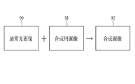
合成画像生成部82は、特殊光画像生成部81で生成された特殊光画像に所定の処理を施して合成用画像を生成するとともに、その生成した合成用画像上に、通常光画像生成部80で生成された通常光画像とを合成して合成画像を生成する。合成画像生成部82は、合成用画像生成部82aと、画像合成部82bとを備えている。
The composite
合成用画像生成部82aは、特殊光画像に対して、ローパスフィルタ(LPF)、バンドパスフィルタ(BPF)、ハイパスフィルタ(HPF)等を用いた周波数処理を施す。HPFや、高周波数の所定周波数帯を透過させるBPFで特殊光画像を周波数フィルタリング処理することによって、粘膜表層の微細血管が抽出(すなわち粘膜中深層の血管等が除去)された特殊光画像が得られる。この周波数フィルタリング後の特殊光画像を「合成用画像」とする。なお、LPBや、低周波数の所定周波数帯を透過させるBPFで特殊光画像を処理することにより、特殊光画像から粘膜中深層の太い血管を抽出(すなわち表層微細血管等を除去)した合成用画像が得られる。 The composition image generation unit 82a performs frequency processing on the special light image using a low pass filter (LPF), a band pass filter (BPF), a high pass filter (HPF), and the like. A special light image is obtained by extracting the fine blood vessels on the surface of the mucosa (that is, removing the blood vessels in the deep mucosa and the like) by frequency filtering the special light image with the HPF or a BPF that transmits a predetermined high frequency band. It is done. The special light image after the frequency filtering is referred to as “composition image”. A special image is processed with LPB or a BPF that transmits a predetermined frequency band of low frequency, thereby extracting a thick blood vessel in the middle mucosa from the special light image (that is, removing superficial fine blood vessels). Is obtained.
なお、周波数フィルタリングの周波数帯域は、観察部位や目的とする画像等に合わせて、適宜、設定することが好ましい。すなわち、LFP、BPF、HPFの組み合わせによって、観察対象の血管を強調する一方、それ以外の血管を抑制することができる。 The frequency band for frequency filtering is preferably set as appropriate in accordance with the observation site, the target image, and the like. That is, the combination of LFP, BPF, and HPF can enhance the blood vessels to be observed while suppressing other blood vessels.
また、特殊光画像から目的部位を抽出あるいは除去する処理は、周波数処理に限定されない。例えば、表層付近の粘膜はB光によって青味を帯びる一方、中深層の粘膜はG光によって緑色を帯びる性質を生かし、特殊光画像から青色成分を除去することにより表層血管を抽出することができ、また、特殊光画像から緑色成分を除去することにより中深層血管を抽出することができる。 Further, the process of extracting or removing the target part from the special light image is not limited to the frequency process. For example, the mucous membrane in the vicinity of the surface layer is bluish by B light, while the mucosa in the middle and deep layers takes advantage of the property of being greenish by G light, and the surface blood vessels can be extracted by removing the blue component from the special light image. Moreover, the middle-layer blood vessel can be extracted by removing the green component from the special light image.
また、表層の微細血管や中深層血管が存在する部分は、その周辺と比べてコントラストが高くなる性質を生かし、所定値以上のコントラストを有する部分(画素)の抽出を行うことで、表層の微細血管や中深層血管が抽出された合成用画像が得られる。なお、抽出時におけるコントラストの閾値は、観察部位、内視鏡の特性、過去の診断結果、シミュレーション等に応じて、適宜設定することができる。 In addition, by taking advantage of the property that the contrast is higher in the area where the superficial microvessels and middle-deep blood vessels are present, the part (pixels) having a contrast of a predetermined value or more is extracted, and the superficial microvessels are extracted. An image for synthesis from which blood vessels and middle-deep blood vessels are extracted is obtained. Note that the contrast threshold value at the time of extraction can be appropriately set according to the observation site, endoscope characteristics, past diagnosis results, simulation, and the like.
また、ガンなどの病変部は表層の微細血管などが特殊な血管パターンを有する特性を生かし、パターンマッチングによってその特殊な血管パターンを抽出することで、ガンなどが抽出された合成用画像が得られる。なお、パターンマッチングは公知の方法を用いることができる。また、血管の特殊パターンの種類は、公知文献に記載されたものを用いてもよく、また典型的な病巣を撮影した画像からサンプリングされたものを用いてもよい。 In addition, a lesion such as a cancer takes advantage of the characteristic that the fine blood vessels on the surface layer have a special blood vessel pattern, and the special blood vessel pattern is extracted by pattern matching, so that a composite image from which the cancer is extracted can be obtained. . A known method can be used for pattern matching. In addition, the types of special blood vessel patterns may be those described in known literature, or those sampled from an image of a typical lesion.
なお、上記で示した周波数処理、色成分の抽出、コントラストの抽出、及び血管パターンによる抽出は、いずれか1つのみを行ってもよく、それらを組み合わせて行ってもよい。 Note that only one of the frequency processing, color component extraction, contrast extraction, and blood vessel pattern extraction described above may be performed, or a combination thereof may be performed.
さらに、上記で示した周波数処理、色成分の抽出、コントラストの抽出、及び血管パターンによる抽出を行った後に、それら処理によって得られた画像において、表層の微細血管等の密集部分が所定の条件を満たす領域(例えば血管の密集具合が高い領域や血管密度が一定値以上の領域など)を更に抽出したものを、合成用画像としてもよい。なお、血管等の密集具合は、空間周波数の測定やMTF(Modulation Transfer Function)の測定等の公知の方法で検出することが好ましい。また、密集具合の閾値は、観察部位、内視鏡の特性、過去の診断結果、シミュレーション等に応じて、適宜設定することができる。 Furthermore, after performing the above-described frequency processing, color component extraction, contrast extraction, and blood vessel pattern extraction, in the image obtained by these processing, a dense portion such as a fine blood vessel on the surface layer satisfies a predetermined condition. A further extracted region (for example, a region where the density of blood vessels is high or a region where the blood vessel density is equal to or higher than a certain value) may be used as a synthesis image. It should be noted that the density of blood vessels and the like is preferably detected by a known method such as spatial frequency measurement or MTF (Modulation Transfer Function) measurement. Further, the threshold value for the degree of congestion can be appropriately set according to the observation site, the characteristics of the endoscope, the past diagnosis result, the simulation, and the like.
画像合成部82bは、図9に示すように、通常光画像生成部80で生成された通常光画像90と、合成用画像生成部82aで生成された合成用画像91とを合成することにより、合成画像92を生成する。したがって、合成画像92は、遠景状態のような光量が不足する状況下においても十分な明るさが確保されているとともに、表層血管や表層微細構造などの観察対象の部位が明瞭化されている。生成された合成画像は、表示装置14に表示される。
As shown in FIG. 9, the image composition unit 82b combines the normal
次に、本発明の作用を図10のフローチャートに沿って説明する。まず、内視鏡装置の切り替えスイッチ17により、特殊光観察モードに設定する。これにより、B−LED,G−LED,R−LEDから、光量値がLb=Lg=Lrに設定されたB光,G光、R光と、光量値がLb>Lg>Lrに設定されたB光,G光、R光とが交互に被検体に照射される。そして、光量値がLb=Lg=LrのB光,G光、R光が照射されたとき(通常光画像取得フレーム)には、その戻り光を撮像素子60で撮像してB1画像信号、G1画像信号、R1画像信号を出力する。一方、光量値がLb>Lg>LrのB光,G光、R光が照射されたとき(特殊光画像取得フレーム)には、その戻り光を撮像素子60で撮像してB2画像信号、G2画像信号、R2画像信号を出力する。
Next, the operation of the present invention will be described with reference to the flowchart of FIG. First, the special light observation mode is set by the
通常光画像取得フレーム時に撮像素子60から出力されたB1画像信号、G1画像信号、R1画像信号に基づいて、通常光画像が生成される。一方、特殊光画像取得フレーム時に撮像素子60から出力されたB2画像信号、G2画像信号に基づいて、特殊光画像が生成される。特殊光画像を生成する際には、B2画像信号をR2画像信号で補正処理した補正B2画像信号と、G2画像信号をR2画像信号で補正処理した補正G2画像信号から特殊光画像を生成する。
A normal light image is generated based on the B1 image signal, the G1 image signal, and the R1 image signal output from the
次に、特殊光画像に対して周波数フィルタリングやバンドパスフィルタなどの周波数処理が施される。その際、HPFや、高周波数の所定周波数帯を透過させるBPFで特殊光画像を周波数処理することによって、粘膜表層の微細血管や微細構造を抽出するとともに、粘膜中深層の血管等を除去する。これにより、表層の微細血管や微細構造が明瞭化された特殊光画像が得られる。この特殊光画像を、通常光画像に合成する合成用画像とする。 Next, frequency processing such as frequency filtering and bandpass filter is performed on the special light image. At that time, the special light image is frequency-processed with HPF or a BPF that transmits a predetermined high frequency band, thereby extracting microvessels and fine structures on the surface layer of the mucosa and removing blood vessels and the like in the middle mucosa. Thereby, a special light image in which the fine blood vessels and the fine structure of the surface layer are clarified is obtained. This special light image is used as a composition image to be combined with the normal light image.
そして、合成用画像と通常光画像を合成することによって、合成画像を生成する。生成された合成画像は、表示装置14に表示される。合成画像は、光量が不足する状況下でも十分な明るさが確保されており、且つ病変部の診断に寄与する表層微細血管等が明瞭化されているため、術者は診断を確実に行うことができる。なお、特殊光観察モードの設定が解除されたら、合成画像の表示は停止する。
Then, a composite image is generated by combining the composite image and the normal light image. The generated composite image is displayed on the
なお、上記実施形態では、B−LED,G−LED,R−LEDを光源装置内に設置したが、図11に示すように、内視鏡装置12のスコープ先端部40に設けてもよい。スコープ先端部40に設けられたB−LED,G−LED,R−LEDは、内視鏡装置12内のLED用通信ケーブル100b,100g,100rを介して、光源装置内のB光量制御部20b、G光量制御部20g、R光量制御部20rによって制御される。このようにスコープ先端部40にB−LED,G−LED,R−LEDを設けることで、B光、G光、R光を減衰させることなく直接的に被検体に照射することができるため、光の利用効率を高めることができる。
In the above embodiment, the B-LED, G-LED, and R-LED are installed in the light source device, but may be provided in the scope
また、上記実施形態では、特殊光画像取得フレーム時に照射する光の光量値の関係を、B光の光量Lb>G光の光量Lg>R光の光量Lrとすることによって、表層血管の明瞭化を行ったが、これに代えて又は加えて、G光の光量Lg又はR光の光量LrをB光の光量よりも大きくすることによって、中深層血管や中深層の構造の明瞭化を行ってもよい。この場合、特殊光画像は、G2画像信号とR2画像信号に基づいて生成する。生成する彩には、例えば、G2画像信号は特殊光画像のB画像及びG画像に割り付けられ、R2画像信号は特殊光画像のR2画像に割り付けることが好ましい。 Further, in the above-described embodiment, the relationship between the light amount values of the light irradiated during the special light image acquisition frame is set such that the light amount Lb of the B light> the light amount Lg of the G light> the light amount Lr of the R light, thereby clarifying the surface blood vessels. In place of or in addition to this, the structure of the middle-deep blood vessel and the middle-deep layer is clarified by making the light quantity Lg of G light or the light quantity Lr of R light larger than the light quantity of B light. Also good. In this case, the special light image is generated based on the G2 image signal and the R2 image signal. For example, the G2 image signal is preferably assigned to the B image and the G image of the special light image, and the R2 image signal is preferably assigned to the R2 image of the special light image.
10 内視鏡システム
11 光源装置
20b B光量制御部
20g G光量制御部
20r R光量制御部
80 通常光画像生成部
81 特殊光画像生成部
81a 信号補正部
82 合成画像生成部
82b 画像合成部
DESCRIPTION OF
Claims (11)
緑色帯域のG光を発する緑色半導体光源と、
赤色帯域のR光を発する赤色半導体光源と、
B光、G光、R光が照射された被検体内を撮像することによって、明るさが互いに異なる通常光画像と特殊光画像とを取得する画像取得手段と、
前記通常光画像を取得する際に照射するB光、G光、R光の第1光量値と、この第1光量値と異なる光量値であって前記特殊光画像を取得する際に照射するB光、G光、R光の第2光量値との切り替え制御を、各半導体光源に対して行う光量制御手段とを備え、
前記光量制御手段は、
表層血管や表層微細構造を明瞭化した特殊光画像を取得するときには、前記B光、G光、R光の第2光量値を、B光の光量>G光の光量>R光の光量の関係にし、
中層血管や中深層の構造を明瞭化した特殊光画像を取得するときには、前記B光、G光、R光の第2光量値を、G光の光量またはR光の光量をB光の光量よりも大きい関係にすることを特徴とする内視鏡システム。 A blue semiconductor light source emitting blue band B light;
A green semiconductor light source emitting G light in the green band;
A red semiconductor light source that emits red light in the red band;
Image acquisition means for acquiring a normal light image and a special light image having different brightness by imaging the inside of the subject irradiated with B light, G light, and R light;
B light, B light, G light, and R light emitted when obtaining the normal light image, and B light emitted when obtaining the special light image having a light quantity value different from the first light quantity value. A light amount control means for performing switching control with respect to the second light amount value of light, G light, and R light for each semiconductor light source
The light amount control means includes
When acquiring a special light image that clarifies the surface blood vessels and the surface microstructure, the second light quantity value of the B light, G light, and R light is expressed as follows: B light quantity> G light quantity> R light quantity West,
When acquiring a special light image that clarifies the structure of the middle blood vessel or the middle deep layer, the second light quantity value of the B light, the G light, and the R light is obtained from the light quantity of the G light or the light quantity of the R light from the light quantity of the B light. Endoscope system characterized by a large relationship.
前記B光、G光、R光の第2光量値を、B光の光量>G光の光量>R光の光量の関係にしたときには、カラー撮像素子を用いた撮像により得られた青色画像信号、緑色画像信号、赤色画像信号のうち、前記青色画像信号を前記特殊光画像のB画像及びG画像に、前記緑色画像信号を前記特殊光画像のR画像に割り付ける請求項1記載の内視鏡システム。 The image acquisition means includes
When the second light quantity value of the B light, G light, and R light has a relationship of B light quantity> G light quantity> R light quantity, a blue image signal obtained by imaging using a color imaging device The endoscope according to claim 1, wherein, among the green image signal and the red image signal, the blue image signal is allocated to the B image and the G image of the special light image, and the green image signal is allocated to the R image of the special light image. system.
ローパスフィルタ、バンドパスフィルタ、ハイパスフィルタの組み合わせたものを特殊光画像に施すことによって、観察対象の血管を強調する一方、それ以外の血管を抑制する請求項1記載の内視鏡システム。 The image acquisition means includes
The endoscope system according to claim 1, wherein a special blood image is subjected to a combination of a low-pass filter, a band-pass filter, and a high-pass filter to enhance a blood vessel to be observed while suppressing other blood vessels.
前記所定の処理が施された特殊光画像と前記通常光画像を合成して合成画像を生成する画像合成部とを有することを特徴とする請求項1記載の内視鏡システム。 An image processing unit for performing predetermined processing on the special light image;
The endoscope system according to claim 1, further comprising an image composition unit configured to compose the special light image subjected to the predetermined processing and the normal light image to generate a composite image.
前記B光を発する青色半導体光源と、
前記G光を発する緑色半導体光源と、
前記R光を発する赤色半導体光源と、
前記通常光画像を取得する際に照射するB光、G光、R光の第1光量値と、この第1光量値と異なる光量値であって前記特殊光画像を取得する際に照射するB光、G光、R光の第2光量値との切り替え制御を、各半導体光源に対して行う光量制御手段とを備え、
前記光量制御手段は、
表層血管や表層微細構造を明瞭化した特殊光画像を取得するときには、前記B光、G光、R光の第2光量値を、B光の光量>G光の光量>R光の光量の関係にし、
中層血管や中深層の構造を明瞭化した特殊光画像を取得するときには、前記B光、G光、R光の第2光量値を、G光の光量またはR光の光量をB光の光量よりも大きい関係にすることを特徴とする内視鏡システムの光源装置。 An endoscope apparatus that images a subject by irradiating blue-band B light, green-band G light, and red-band R light to acquire a normal light image and a special light image having different brightnesses. In contrast, in a light source device of an endoscope system that supplies illumination light for illuminating the inside of a subject,
A blue semiconductor light source emitting the B light;
A green semiconductor light source emitting the G light;
A red semiconductor light source emitting the R light;
B light, B light, G light, and R light emitted when obtaining the normal light image, and B light emitted when obtaining the special light image having a light quantity value different from the first light quantity value. A light amount control means for performing switching control with respect to the second light amount value of light, G light, and R light for each semiconductor light source,
The light amount control means includes
When acquiring a special light image that clarifies the surface blood vessels and the surface microstructure, the second light quantity value of the B light, G light, and R light is expressed as follows: B light quantity> G light quantity> R light quantity West,
When acquiring a special light image that clarifies the structure of the middle blood vessel or the middle deep layer, the second light quantity value of the B light, the G light, and the R light is obtained from the light quantity of the G light or the light quantity of the R light from the light quantity of the B light. A light source device for an endoscope system characterized by having a large relationship.
光量制御手段が、前記通常光画像を取得する際に照射するB光、G光、R光の第1光量値と、この第1光量値と異なる光量値であって前記特殊光画像を取得する際に照射するB光、G光、R光の第2光量値との切り替え制御を、各半導体光源に対して行うステップであり、光量制御手段が、表層血管や表層微細構造を明瞭化した特殊光画像を取得するときには、前記B光、G光、R光の第2光量値を、B光の光量>G光の光量>R光の光量の関係にし、中層血管や中深層の構造を明瞭化した特殊光画像を取得するときには、前記B光、G光、R光の第2光量値を、G光の光量またはR光の光量をB光の光量よりも大きい関係にするステップを有することを特徴とする内視鏡システムの作動方法。 A blue semiconductor light source emitting blue band B light, a green semiconductor light source emitting green band G light, a red semiconductor light source emitting red band R light, and an image acquisition means comprising the B light and the G light In the operation method of the endoscope system, the method includes: acquiring a normal light image and a special light image having different brightness by imaging the inside of the subject irradiated with the R light.
The light quantity control means obtains the special light image having a first light quantity value of B light, G light, and R light irradiated when obtaining the normal light image, and a light quantity value different from the first light quantity value. Is a step in which each semiconductor light source is controlled to switch to the second light quantity value of the B light, G light, and R light to be irradiated, and the light quantity control means specially clarifies the superficial blood vessels and superficial fine structures. When acquiring a light image, the second light quantity value of the B light, G light, and R light is set such that the light quantity of the B light> the light quantity of the G light> the light quantity of the R light, and the structure of the middle layer blood vessel and the middle depth layer is clear When acquiring a special light image, the second light amount value of the B light, G light, and R light has a step in which the light amount of G light or the light amount of R light is greater than the light amount of B light. An operation method of an endoscope system characterized by the above.
Priority Applications (1)
| Application Number | Priority Date | Filing Date | Title |
|---|---|---|---|
| JP2014253817A JP5970054B2 (en) | 2014-12-16 | 2014-12-16 | Endoscope system, light source device for endoscope system, and method for operating endoscope system |
Applications Claiming Priority (1)
| Application Number | Priority Date | Filing Date | Title |
|---|---|---|---|
| JP2014253817A JP5970054B2 (en) | 2014-12-16 | 2014-12-16 | Endoscope system, light source device for endoscope system, and method for operating endoscope system |
Related Parent Applications (1)
| Application Number | Title | Priority Date | Filing Date |
|---|---|---|---|
| JP2011131393A Division JP5670264B2 (en) | 2011-06-13 | 2011-06-13 | Endoscope system and method for operating endoscope system |
Publications (2)
| Publication Number | Publication Date |
|---|---|
| JP2015062728A JP2015062728A (en) | 2015-04-09 |
| JP5970054B2 true JP5970054B2 (en) | 2016-08-17 |
Family
ID=52831141
Family Applications (1)
| Application Number | Title | Priority Date | Filing Date |
|---|---|---|---|
| JP2014253817A Active JP5970054B2 (en) | 2014-12-16 | 2014-12-16 | Endoscope system, light source device for endoscope system, and method for operating endoscope system |
Country Status (1)
| Country | Link |
|---|---|
| JP (1) | JP5970054B2 (en) |
Families Citing this family (1)
| Publication number | Priority date | Publication date | Assignee | Title |
|---|---|---|---|---|
| JP7105300B2 (en) * | 2018-04-24 | 2022-07-22 | オリンパス株式会社 | Endoscopic system and method of operating the endoscopic system |
Family Cites Families (2)
| Publication number | Priority date | Publication date | Assignee | Title |
|---|---|---|---|---|
| JP4917822B2 (en) * | 2006-03-30 | 2012-04-18 | 富士フイルム株式会社 | Endoscope device |
| JP5098030B2 (en) * | 2008-04-02 | 2012-12-12 | 富士フイルム株式会社 | Imaging apparatus, imaging method, and program |
-
2014
- 2014-12-16 JP JP2014253817A patent/JP5970054B2/en active Active
Also Published As
| Publication number | Publication date |
|---|---|
| JP2015062728A (en) | 2015-04-09 |
Similar Documents
| Publication | Publication Date | Title |
|---|---|---|
| JP5670264B2 (en) | Endoscope system and method for operating endoscope system | |
| US9675238B2 (en) | Endoscopic device | |
| JP5303012B2 (en) | Endoscope system, processor device for endoscope system, and method for operating endoscope system | |
| JP5623348B2 (en) | Endoscope system, processor device for endoscope system, and method for operating endoscope system | |
| JP6461739B2 (en) | Image processing apparatus, endoscope system, and method of operating image processing apparatus | |
| JP5460506B2 (en) | Endoscope apparatus operating method and endoscope apparatus | |
| JP5496075B2 (en) | Endoscopic diagnosis device | |
| JP5159904B2 (en) | Endoscopic diagnosis device | |
| JP5501210B2 (en) | Image processing device | |
| JP5485215B2 (en) | Endoscope device | |
| JP5222934B2 (en) | Endoscope system, processor device for endoscope system, and method for operating endoscope system | |
| CN108830825B (en) | Endoscope system and method for operating same | |
| JP5757891B2 (en) | Electronic endoscope system, image processing apparatus, operation method of image processing apparatus, and image processing program | |
| US10070771B2 (en) | Image processing apparatus, method for operating image processing apparatus, computer-readable recording medium, and endoscope device | |
| US9414739B2 (en) | Imaging apparatus for controlling fluorescence imaging in divided imaging surface | |
| JP2012029703A (en) | Method for controlling endoscope apparatus, and endoscope apparatus | |
| JP5844230B2 (en) | Endoscope system and operating method thereof | |
| JP5948203B2 (en) | Endoscope system and operating method thereof | |
| JP6137892B2 (en) | Imaging system | |
| JP2012125402A (en) | Endoscope system, processor device thereof, and method of obtaining function information | |
| US10863149B2 (en) | Image processing apparatus, image processing method, and computer readable recording medium | |
| JP5970054B2 (en) | Endoscope system, light source device for endoscope system, and method for operating endoscope system | |
| JP2013102897A (en) | Endoscopic diagnostic apparatus | |
| WO2017046876A1 (en) | Endoscope system, image processing apparatus, and image processing method | |
| JP2013102898A (en) | Endoscopic diagnostic apparatus |
Legal Events
| Date | Code | Title | Description |
|---|---|---|---|
| A977 | Report on retrieval |
Free format text: JAPANESE INTERMEDIATE CODE: A971007 Effective date: 20151019 |
|
| A131 | Notification of reasons for refusal |
Free format text: JAPANESE INTERMEDIATE CODE: A131 Effective date: 20151202 |
|
| A521 | Request for written amendment filed |
Free format text: JAPANESE INTERMEDIATE CODE: A523 Effective date: 20160118 |
|
| TRDD | Decision of grant or rejection written | ||
| A01 | Written decision to grant a patent or to grant a registration (utility model) |
Free format text: JAPANESE INTERMEDIATE CODE: A01 Effective date: 20160622 |
|
| A61 | First payment of annual fees (during grant procedure) |
Free format text: JAPANESE INTERMEDIATE CODE: A61 Effective date: 20160708 |
|
| R150 | Certificate of patent or registration of utility model |
Ref document number: 5970054 Country of ref document: JP Free format text: JAPANESE INTERMEDIATE CODE: R150 |
|
| R250 | Receipt of annual fees |
Free format text: JAPANESE INTERMEDIATE CODE: R250 |
|
| R250 | Receipt of annual fees |
Free format text: JAPANESE INTERMEDIATE CODE: R250 |
|
| R250 | Receipt of annual fees |
Free format text: JAPANESE INTERMEDIATE CODE: R250 |
|
| R250 | Receipt of annual fees |
Free format text: JAPANESE INTERMEDIATE CODE: R250 |
|
| R250 | Receipt of annual fees |
Free format text: JAPANESE INTERMEDIATE CODE: R250 |
|
| R250 | Receipt of annual fees |
Free format text: JAPANESE INTERMEDIATE CODE: R250 |