JP5969622B2 - Energy storage assembly having over-rotation restricting means and electrical switching device using the same - Google Patents
Energy storage assembly having over-rotation restricting means and electrical switching device using the same Download PDFInfo
- Publication number
- JP5969622B2 JP5969622B2 JP2014544754A JP2014544754A JP5969622B2 JP 5969622 B2 JP5969622 B2 JP 5969622B2 JP 2014544754 A JP2014544754 A JP 2014544754A JP 2014544754 A JP2014544754 A JP 2014544754A JP 5969622 B2 JP5969622 B2 JP 5969622B2
- Authority
- JP
- Japan
- Prior art keywords
- catchment
- energy storage
- protrusion
- storage assembly
- cast member
- Prior art date
- Legal status (The legal status is an assumption and is not a legal conclusion. Google has not performed a legal analysis and makes no representation as to the accuracy of the status listed.)
- Active
Links
Images


Classifications
-
- H—ELECTRICITY
- H01—ELECTRIC ELEMENTS
- H01H—ELECTRIC SWITCHES; RELAYS; SELECTORS; EMERGENCY PROTECTIVE DEVICES
- H01H3/00—Mechanisms for operating contacts
- H01H3/22—Power arrangements internal to the switch for operating the driving mechanism
- H01H3/30—Power arrangements internal to the switch for operating the driving mechanism using spring motor
- H01H3/3005—Charging means
- H01H3/3015—Charging means using cam devices
-
- H—ELECTRICITY
- H01—ELECTRIC ELEMENTS
- H01H—ELECTRIC SWITCHES; RELAYS; SELECTORS; EMERGENCY PROTECTIVE DEVICES
- H01H33/00—High-tension or heavy-current switches with arc-extinguishing or arc-preventing means
- H01H33/02—Details
- H01H33/28—Power arrangements internal to the switch for operating the driving mechanism
- H01H33/40—Power arrangements internal to the switch for operating the driving mechanism using spring motor
Description
関連出願の相互参照
本出願は、2011年11月29日に提出された米国特許出願第13/306374号の優先権を主張し、その内容は、参照することにより、ここに含まれる。
CROSS-REFERENCE TO RELATED APPLICATIONS This application claims the priority of US Patent Application No. 13/306374 which was filed on November 29, 2011, the contents of which, by reference, are included here.
背景技術
技術分野
ここに開示された概念は、概して電気的スイッチング装置に関し、より具体的には、電気的スイッチング装置用の蓄勢(charging)アセンブリに関する。また、本開示の概念は、サーキットブレーカ等の電気的スイッチング装置に関する。
Background art
TECHNICAL FIELD The concepts disclosed herein generally relate to electrical switching devices, and more specifically to a charging assembly for electrical switching devices. The concept of the present disclosure also relates to an electrical switching device such as a circuit breaker.
背景技術情報
サーキットブレーカ等の電気的スイッチ装置は、例えば電流過負荷、短絡、異常電圧、及び、他の故障状態のような電気的故障状態から電気システムを保護するために設けられる。一般的に、サーキットブレーカは、作動機構を含み、この作動機構は、例えばトリップユニットにより、そのような故障状態の検出に応答して、電気接点アセンブリを開いて、電気システムの導体を通る電流を遮断する。この電気接点アセンブリは、固定電気接点、及び、固定電気接点から離間した対応する可動電気接点を含む。
BACKGROUND ART Electrical switch devices such as circuit breakers are provided to protect electrical systems from electrical fault conditions such as current overloads, short circuits, abnormal voltages, and other fault conditions. In general, a circuit breaker includes an actuation mechanism that opens an electrical contact assembly in response to detection of such a fault condition, eg, by a trip unit, to pass current through a conductor in the electrical system. Cut off. The electrical contact assembly includes a stationary electrical contact and a corresponding movable electrical contact spaced from the stationary electrical contact.
これらの部品の中で、特に、ある種の低電圧及び中電圧サーキットブレーカの作動機構は、例えば、一般的に、電極シャフト、トリップアクチュエータアセンブリ、閉動作アセンブリ、及び、開動作アセンブリを含む。トリップアクチュエータアセンブリは、トリップユニットに応答して、作動機構を駆動する。閉動作アセンブリ及び開動作アセンブリは、いくつかの共通の要素を含むことができ、これらは、可動電気接点を固定電気接点から離間した第1の開位置と、固定電気接点に電気的に接触した第2の閉位置との間で移動させるように構成される。具体的には、可動電気接点は、電極シャフトに結合される。閉動作アセンブリ及び開動作アセンブリの両方の要素は、電極シャフトに回動可能に結合されており、電極シャフトを回動させて電気接点を開閉する。蓄勢センブリは、複数のエネルギー蓄積機構を含み、閉動作アセンブリの作動を補助するために使用されることが多い。 Among these components, in particular, certain low and medium voltage circuit breaker actuation mechanisms typically include, for example, an electrode shaft, a trip actuator assembly, a closing motion assembly, and an opening motion assembly. The trip actuator assembly drives the actuation mechanism in response to the trip unit. The closed motion assembly and the open motion assembly may include several common elements that are in electrical contact with the fixed electrical contact and a first open position that separates the movable electrical contact from the fixed electrical contact. It is configured to move between the second closed position. Specifically, the movable electrical contact is coupled to the electrode shaft. Both elements of the closing motion assembly and the opening motion assembly are pivotally coupled to the electrode shaft and rotate the electrode shaft to open and close the electrical contacts. The energy storage assembly includes a plurality of energy storage mechanisms and is often used to assist in the operation of the closed motion assembly.
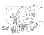
例えば、図1A及び1Bに示されるように、サーキットブレーカ2は、限定はしないが、例えば、複数の閉動作スプリング4(図1Aにおいては、1つの閉動作スプリング4の一部が簡略化された形態で示される。)等の直接駆動のエネルギー蓄積機構を有する。そのようなサーキットブレーカ2の蓄勢アセンブリ6は、一般的に、複数のカム10,12を有するカムシャフト8及びキャッチメント14を含む。図1A及び1Bの例では、このキャッチメント14は、サーキットブレーカ2のサイドプレート16に回動可能に結合されている。そのような装置では、スプリングアセンブリは、上述の閉動作スプリング4及びこのスプリング4によって付勢されるスプリングキャスト(spring casting)18を含み、カムシャフト8の作動によって蓄勢され、解放されて、解放されたスプリング4は、閉動作アセンブリのメイントグルリンク(図示せず)を直接駆動する。スプリング4が解放されたとき、キャッチメントカム12は、解放されており、蓄勢方向(例えば、図1Aにおいて矢印20の方向である反時計方向)に回転し続ける。これが充分に回転したとき、スプリング4の解放を妨げて、サーキットブレーカ2が完全に閉じるのを阻止する。この望ましくない状態は、一般的にカムシャフト過回転といわれる。キャッチメント14は、一般的に、そのようなカムシャフト8の過回転を防止する(複数の)カムと協働するように構成されているが、特に長期間の使用後、キャッチメント14の当接面22及び/又は対応するキャッチメントカム12のキャッチメント面24は、摩耗又は損傷して(例えば図1Bの損傷又は変形した面22´,24´参照)、キャッチメントの作動不良が起こる可能性がある。
For example, as shown in FIGS. 1A and 1B, the circuit breaker 2 is not limited to, for example, a plurality of closing operation springs 4 (in FIG. 1A, a part of one closing operation spring 4 is simplified). A direct-drive energy storage mechanism. The storage assembly 6 of such a circuit breaker 2 generally includes a camshaft 8 and a
このため、蓄勢アセンブリ、及び、蓄勢アセンブリを使用するサーキットブレーカ等の電気的スイッチング装置には、改善の余地がある。 For this reason, there exists room for improvement in electrical switching apparatuses, such as an energy storage assembly and a circuit breaker which uses an energy storage assembly.
これらの要求及び他の要求は、サーキットブレーカ等の電気的スイッチングアセンブリ用の蓄勢アセンブリを対象とする本開示の概念の実施形態によって達成される。特に、この蓄勢アセンブリは、閉動作スプリングキャストと協働して、カムシャフトの移動を制御(例えば、過回転を規制)するキャッチメントを含む。 These and other needs are met by embodiments of the concepts of the present disclosure directed to a storage assembly for an electrical switching assembly such as a circuit breaker. In particular, the energy storage assembly includes a catchment that cooperates with the closing motion spring cast to control the movement of the camshaft (e.g., restrict over-rotation).
本開示の概念の一形態として、電気的スイッチング装置用の蓄勢アセンブリが提供される。この電気的スイッチング装置は、ハウジングと、該ハウジングによって囲まれた分離可能な接点と、分離可能な前記接点を開閉するための作動機構とを含む。蓄勢アセンブリは、蓄積位置と解放位置との間で移動可能なエネルギー蓄積機構と、前記エネルギー蓄積機構に結合されてこれと共に移動可能で突起部を含むキャスト部材と、前記ハウジングに回動可能に結合されるように構成されて複数のカムを含むカムシャフトと、前記ハウジングに回動可能に結合されるように構成されて当接面及び突出部を有するキャッチメントとを備える。前記キャッチメントの前記当接面は、前記カムの対応する1つと協働して、前記カムシャフトの過回転に抵抗する。前記キャッチメントの突出部は、前記キャスト部材の前記突起部と協働して、前記キャッチメントと前記カムの対応する1つとの所望の関係を保持する。 As one form of the concept of the present disclosure, a storage assembly for an electrical switching device is provided. The electrical switching device includes a housing, a separable contact surrounded by the housing, and an actuating mechanism for opening and closing the separable contact. The energy storage assembly includes an energy storage mechanism that is movable between a storage position and a release position, a cast member that is coupled to the energy storage mechanism and is movable with the energy storage mechanism and includes a protrusion, and is rotatable with respect to the housing. A camshaft configured to be coupled and including a plurality of cams; and a catchment configured to be pivotally coupled to the housing and having a contact surface and a protrusion. The abutment surface of the catchment cooperates with a corresponding one of the cams to resist over-rotation of the camshaft. The protrusion of the catchment cooperates with the protrusion of the cast member to maintain the desired relationship between the catchment and the corresponding one of the cams.
前記キャッチメントは、更に、ピボット部材、第1部分、第2部分及びだ3部分を含むことができる。ピボット部材は、第1部分を電気的スイッチング装置のハウジングに回動可能に結合するように構成され、第2部分は、対応するカムの1つと協働し、第3部分は、キャスト部材の突起部と協働する。当接面は、キャッチメントの第2部分に配置され、突出部は、キャッチメントの第3部分位に配置され、突出部は、当接面の付近でキャッチメントから外側へ延びる。キャッチメントは、ワンピースの部材とすることができ、突出部は、ワンピース部材の第3部分から外側へ延びる略長方形である。突出部は、外側縁部を有し、キャッチメントの当接面が対応するカムの1つに係合したとき、突出部の外側縁部は、キャスト部材の突起部と協働する。 The catchment may further include a pivot member, a first part, a second part and a three part. The pivot member is configured to pivotally couple the first portion to the housing of the electrical switching device, the second portion cooperates with one of the corresponding cams, and the third portion is a protrusion of the cast member. Work with the department. The abutment surface is disposed at the second portion of the catchment, the protrusion is disposed at the third portion of the catchment, and the protrusion extends outward from the catchment near the abutment surface. The catchment can be a one-piece member and the protrusion is generally rectangular extending outwardly from the third portion of the one-piece member. The protrusion has an outer edge, and the outer edge of the protrusion cooperates with the protrusion of the cast member when the abutment surface of the catchment engages one of the corresponding cams.
キャスト部材は、ワンピースのスプリングキャスト部材とすることができ、突起部は、ワンピースのスプリングキャスト部材から横方向に外側へ突出して保持縁部を含む。ワンピースのスプリングキャスト部材保持縁部は、キャッチメントの外側縁部を保持し、これにより、キャッチメントの当接面が対応するカムの1つを解放するのを防止する。 The cast member may be a one-piece spring cast member, and the protrusion protrudes laterally outward from the one-piece spring cast member and includes a retaining edge. The one-piece spring cast member retaining edge holds the outer edge of the catchment, thereby preventing the catchment abutment surface from releasing one of the corresponding cams.
本開示の他の形態として、上述の蓄勢アセンブリを使用する電気的スイッチング装置が開示されている。 As another form of the present disclosure, an electrical switching device using the above-described energy storage assembly is disclosed.
本開示の概念の完全な理解は、以下の好ましい実施形態の詳細な説明を添付図面に関連して読むことにより、得ることができる。 A full understanding of the concepts of the present disclosure can be obtained by reading the following detailed description of the preferred embodiments in conjunction with the accompanying drawings.
ここで使用される方向の表現、例えば、時計回り、反時計回り、左、右、上方、下方、及び、これらの派生語等は、図示されたその要素の方向に関係し、明示的な提示がない限り、請求の範囲を限定するものではない。
ここで使用される2つ又はそれ以上の部分が一体に「結合」されているという表現は、それらの部分がそれぞれ直接的に一体に結合、又は、1つ又はそれ以上の中間部分を介して結合されていることを意味する。
ここで使用される「数」という用語は、1又は1以上の整数(すなわち、複数)を意味する。
The direction representations used here, for example, clockwise, counterclockwise, left, right, up, down, and their derivatives, etc., relate to the direction of the element shown and are explicitly presented. Unless otherwise, the claims are not limited.
As used herein, the expression that two or more parts are “coupled” together means that the parts are each directly coupled together or via one or more intermediate parts. Means they are connected.
As used herein, the term “number” means one or an integer greater than or equal to one (ie, a plurality).
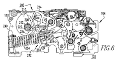
図2〜7は、例えば、限定はしないが、サーキットブレーカ102等の電気スイッチング装置用の蓄勢アセンブリ200を示す。このサーキットブレーカ102は、ハウジング104と、ハウジング104によって囲まれた分離可能な接点106(図2において概略化して示す)と、分離可能な接点106を開閉する作動機構108(図2に概略的に示される)を含む(図2)。
2-7 illustrate a
図2に最もよく示されるように、蓄勢アセンブリ200は、好ましくは、例えば、限定はしないが、閉動作スプリング204(図2に一部が示される)等のエネルギー蓄積機構を含み、この閉動作スプリング204は、蓄勢位置(図5)と解放位置(図2、4及び7)との間で移動可能である。キャスト(cast)部材218は、閉動作スプリング204に結合されて、これと共に移動可能(例えば、限定はしないが、図2から見て左右に矢印の方向に)である。キャスト部材218は、突起部220を含む。カムシャフト208は、サーキットブレーカハウジング104に回動可能に結合され、また、複数のカム210,212(この例では、2つのカムが示されている)を含む。キャッチメント214もハウジング104に回動可能に結合されており、このキャッチメント214は、当接面224及び突出部226を含む。以下に詳細に説明するように、キャッチメント214の当接面224は、対応する1つのカム212、具体的には、カム212のキャッチメント面222と協働して、カムシャフト208の過回転を防止する。更に、ここに開示された概念に従って、前述のキャッチメント214の突出部226は、キャスト部材218の突起部220と協働して、キャッチメント214とカム212との間の望ましい関係を維持する。
As best shown in FIG. 2, the
したがって、当然のことながら、いくつかある利点の中で特に、本開示の概念の突起部220及び突出部226の特徴は、カム212のキャッチメント面22とキャッチメント214の当接面224との間で生じてしまう当り損ねの当接を防止するように、キャッチメント214とスプリングキャスト218とを連動させることにより、キャッチメント214の作動を増強するように機能することである。このように、本開示の蓄勢アセンブリ200は、カムシャフト208の過回転を防止して、これに関係する損傷を防止するためのバックアップ機構を提供する。例えば、限定はしないが、ブレーカの振動等の問題は、従来技術のキャッチメント(例えば、限定はしないが、図1A及び1Bのキャッチメント14参照)をカムシャフトの過回転を許す位置(例えば図1B参照)へ移動させる虞がある。さらに、長期間の経過により(すなわち、長期間の使用後)、キャッチメントの当接機構(例えば、限定はしないが、図1Aのキャッチメント14の面24参照)及び/又はカムシャフトの噛合い機構(例えば、図1Aのカムシャフト面22参照)は、カムシャフトに過回転を引き起こさせる当り損ねの衝突すなわち当接を許すような損傷(例えば、図1Bの変形した面22´,24´参照)を受けている可能性がある。本開示の概念は、キャッチメント214の作動を改善し、これにより、そのような潜在的な問題に対処し、それを防止する。
Thus, it should be appreciated that the features of the
より具体的には、図2に最もよく示されるように、ここに図示されて説明された限定ではない例示において、キャッチメント214は、好ましくは、ピボット部材228、第1部分230、第2部分232及び第3部分234を含む。ピボット部材228は、第1部分230をサーキットブレーカのハウジング104、具体的には、そのサイドプレート110(図2において隠れ線で一部が示される)に回動可能に結合する。第2部分232は、カム212と協働し、第3部分234は、キャスト部材218の突起部220と協働する。ここに図示されて説明された例では、当接面224は、キャッチメント214の第2部分232に配置され、突出部226は、キャッチメント214の第3部分234に配置されている。そして、突出部226は、図示のように、キャッチメント214から外側に当接面224の付近に延びている。引続き図2及び図4〜7を参照して、キャッチメント214は、好ましくは、単一部材で、突出部226は、その第3部分234から外側に延びる略長方形の部分である。
More specifically, in the non-limiting illustration shown and described herein, as best shown in FIG. 2, the
図2に最もよく示されるように、突出部226は、外側縁部236を有する。キャッチメント214の当接面224が対応するカム212、具体的にはそのキャッチメント面222に当接したとき、又は、そこに接近したとき(例えば、図2、5及び6参照)、突出部226の外側縁部236は、前述のキャスト部材218の突起部220と協働する。
As best shown in FIG. 2, the
キャスト部材218は、好ましくは、ワンピースのスプリングキャスト部材で、突起部220は、ワンピースのスプリングキャスト部材218から横方向外側に突出し、また、保持縁部238を含む。これにより、保持縁部238は、図2、5及び6に示されるように、キャッチメント214の外側縁部236を保持し、これにより、キャッチメント214の当接面224が対応するカム212を完全に解放するのを防止し、及び/又は、前述のカムシャフトの過回転及び/又はカム212及びキャッチメント214のそれぞれの表面222、224間の当り損ねの当接(例えば、当接及び反発し損ない)の問題を防止する。当然のことながら、例示のスプリングキャスト部材218の突起部220は、ワンピースのスプリングキャスト部材218のキャスト構造であるが、本開示の概念の範囲から逸脱することなく、キャッチメント214の運動を適切に制御するキャッチメントの構造(例えば、限定はしないが、突出部226)と適切に協働するために、適当なあらゆる公知の又は適当な代替形式の突起の形状及び/又は構造を使用することができる。例えば、限定はしないが、スプリングキャスト部材218のスロット(図示せず)内のキャッチメント結合ピン(図示せず)、あるいは、リンク機構アセンブリ(図示せず)等の相対的により複雑な結合構造(図示せず)が可能である。
The
以上に述べたように、例示のエネルギー蓄積機構は、閉動作スプリング204である。閉動作スプリング204は、両端の第1及び第2端部240,242(図2及び4〜7)を含む。スプリングキャスト部材218は、閉動作スプリング204の第2端部242に配置されて、図2に示すように、第2端部242と共に矢印300の方向に移動する。例示のカムシャフト208は、上述のように、カムシャフト208回りに回動して閉動作スプリング204を蓄勢する蓄勢カム210である第1カムと、カムシャフト208回りに回動してキャッチメント214の当接面224に係脱するキャッチメントカム212である第2カムとを含む。
As mentioned above, an exemplary energy storage mechanism is the
図4〜7は、図3のサーキットブレーカ102の断面を示し、このサーキットブレーカ102の様々な作動状態における蓄勢アセンブリ200を図示している。さらに具体的には、図4は、解放及びトリップ状態のサーキットブレーカ102を示し、図5は、蓄勢されて開状態のサーキットブレーカ102を示し、図6は、閉動作の過程にあるサーキットブレーカ102を示し、このとき、スプリングキャスト部材218は、例えば、過度のカムシャフト回転力により、キャッチメント214が押下げられている場合に(図6の状態から下方へ)、キャッチメント214を止める位置にあり、また、図7は、解放されて閉状態にあるサーキットブレーカ102を示す。
4-7 illustrate a cross-section of the
したがって、当然のことながら、開示された蓄勢アセンブリ200は、独特なキャッチメント204及びスプリングキャスト部材218の構造(例えば、限定はしないが、スプリングキャスト部材218の突起部220及びキャッチメント214の突出部226)を含み、この構造は、相互に作用して、スプリングキャスト部材218が完全に閉じた位置に充分に接近するまで、カムシャフト208がキャッチメント214をすり抜ける(例えば過回転)のを防止する。このように、この開示された概念は、カムシャフトの過回転の原因となり得るカム212及びキャッチメント214の当り損ね及び/又は損傷を防止するようにキャッチメント214とスプリングキャスト部材218とを連動させることにより、キャッチメントの作動を増強するように機能する。
Thus, it will be appreciated that the disclosed
本開示の概念の具体的な実施形態を詳細に説明してきたが、当業者には当然のことながら、本開示の全体の教示に照らして、これらの詳細に対する様々な修正及び変更が展開可能である。したがって、開示された具体的な構造は、説明のためのものに過ぎず、添付された請求の範囲の全範囲及びその全ての均等物によって与えられるべき本開示の概念の範囲を限定するものではない。 Although specific embodiments of the concepts of the present disclosure have been described in detail, those skilled in the art will recognize that various modifications and changes to these details can be made in light of the overall teachings of the present disclosure. is there. Accordingly, the specific structures disclosed are for illustrative purposes only and are not intended to limit the scope of the present disclosure's concepts to be provided by the full scope of the appended claims and all equivalents thereof. Absent.
Claims (12)
前記電気的スイッチング装置(102)は、ハウジング(104)と、該ハウジングによって囲まれた分離可能な接点(106)と、該接点(106)を開閉する作動機構(108)と、を含み、
前記蓄勢アセンブリ(200)は、蓄勢位置と解放位置との間で移動可能なエネルギー蓄積機構(204)と、
前記エネルギー蓄積機構(204)に結合されて、これと共に移動可能で、突起部(220)を含むキャスト部材(218)と、
前記ハウジング(104)に回動可能に結合される構造で、複数のカム(210,212)を含むカムシャフト(208)と、
前記ハウジング(104)に回動可能に結合される構造で、当接面(224)及び突出部(226)を有するキャッチメント(214)と、を備え、
前記キャッチメント(214)の前記当接面(224)は、複数の前記カムの1つ(212)と協働して、前記カムシャフト(208)の過回転に抵抗し、
前記キャッチメント(214)の前記突出部(226)は、前記キャスト部材(218)の前記突起部(220)と協働して、前記キャッチメント(214)と対応する前記カムの1つ(212)との間の望ましい関係を維持することを特徴とする蓄勢アセンブリ。 A storage assembly (200) for an electrical switching device (102) comprising:
The electrical switching device (102) includes a housing (104), a separable contact (106) surrounded by the housing, and an actuating mechanism (108) for opening and closing the contact (106);
The energy storage assembly (200) includes an energy storage mechanism (204) movable between a power storage position and a release position;
A cast member (218) coupled to the energy storage mechanism (204) and movable therewith and including a protrusion (220);
A camshaft (208) that is pivotally coupled to the housing (104) and includes a plurality of cams (210, 212);
A catchment (214) that is pivotally coupled to the housing (104) and has an abutment surface (224) and a protrusion (226);
The abutment surface (224) of the catchment (214) cooperates with one of the plurality of cams (212) to resist over-rotation of the camshaft (208);
The protrusion (226) of the catchment (214) cooperates with the protrusion (220) of the cast member (218) to support one of the cams (212) corresponding to the catchment (214). A storage assembly characterized by maintaining a desirable relationship between
Applications Claiming Priority (3)
| Application Number | Priority Date | Filing Date | Title |
|---|---|---|---|
| US13/306,374 | 2011-11-29 | ||
| US13/306,374 US8642905B2 (en) | 2011-11-29 | 2011-11-29 | Charging assembly with over rotation control and electrical switching apparatus employing same |
| PCT/US2012/064594 WO2013081803A1 (en) | 2011-11-29 | 2012-11-12 | Charging assembly with over rotation control and electrical switching apparatus employing same |
Publications (2)
| Publication Number | Publication Date |
|---|---|
| JP2015503197A JP2015503197A (en) | 2015-01-29 |
| JP5969622B2 true JP5969622B2 (en) | 2016-08-17 |
Family
ID=47326329
Family Applications (1)
| Application Number | Title | Priority Date | Filing Date |
|---|---|---|---|
| JP2014544754A Active JP5969622B2 (en) | 2011-11-29 | 2012-11-12 | Energy storage assembly having over-rotation restricting means and electrical switching device using the same |
Country Status (9)
| Country | Link |
|---|---|
| US (1) | US8642905B2 (en) |
| EP (1) | EP2786386B1 (en) |
| JP (1) | JP5969622B2 (en) |
| CN (1) | CN104126209B (en) |
| BR (1) | BR112014011978A2 (en) |
| CA (1) | CA2852493C (en) |
| IN (1) | IN2014KN00818A (en) |
| MX (1) | MX2014006459A (en) |
| WO (1) | WO2013081803A1 (en) |
Families Citing this family (3)
| Publication number | Priority date | Publication date | Assignee | Title |
|---|---|---|---|---|
| CN105304367B (en) * | 2015-12-02 | 2020-01-14 | 上海航空电器有限公司 | Quick action switching mechanism of button switch |
| US9905379B2 (en) | 2016-01-21 | 2018-02-27 | Eaton Corporation | Charging ram assembly, and pin assembly and securing method therefor |
| CN111081491B (en) * | 2019-12-14 | 2021-12-21 | 宁波木易电气有限公司 | Air outlet mechanism of gas insulated switchgear |
Family Cites Families (14)
| Publication number | Priority date | Publication date | Assignee | Title |
|---|---|---|---|---|
| JPS61161844U (en) * | 1985-03-25 | 1986-10-07 | ||
| US6064021A (en) * | 1999-09-08 | 2000-05-16 | Eaton Corporation | Clutch assembly for electrical switching apparatus with large compression close spring |
| US6437269B1 (en) * | 2001-08-07 | 2002-08-20 | Eaton Corporation | Spring powered electrical switching apparatus with anti-rollover cam |
| US7186937B1 (en) | 2006-03-30 | 2007-03-06 | Eaton Corporation | Rotational backlash compensating cam for stored energy circuit breaker charging motor control |
| US7294804B1 (en) | 2007-03-29 | 2007-11-13 | Eaton Corporation | Energy dissipating spring seat |
| US7449653B2 (en) * | 2007-03-29 | 2008-11-11 | Eaton Corporation | Positive resetting close latch for closing electrical switching apparatus |
| US7633031B2 (en) * | 2007-03-29 | 2009-12-15 | Eaton Corporation | Spring driven ram for closing a electrical switching apparatus |
| US7449652B2 (en) | 2007-03-29 | 2008-11-11 | Eaton Corporation | Catchment mechanism to prevent camshaft over-rotation during closure in a direct-drive stored energy mechanism |
| US7586055B2 (en) | 2007-04-10 | 2009-09-08 | Eaton Corporation | Over running clutch for a direct drive motor operator |
| US7687733B2 (en) | 2007-06-06 | 2010-03-30 | Eaton Corporation | Interlock assembly for a stored energy mechanism |
| US7696448B2 (en) | 2007-06-08 | 2010-04-13 | Eaton Corporation | Closing protection mechanism for a closing assembly over-toggle linkage |
| US7518076B1 (en) | 2008-04-01 | 2009-04-14 | Eaton Corporation | Electrical switching apparatus, and charging assembly and interlock assembly therefor |
| US8058580B2 (en) * | 2009-09-16 | 2011-11-15 | Eaton Corporation | Electrical switching apparatus and linking assembly therefor |
| US8063328B2 (en) * | 2009-09-16 | 2011-11-22 | Eaton Corporation | Electrical switching apparatus and charging assembly therefor |
-
2011
- 2011-11-29 US US13/306,374 patent/US8642905B2/en active Active
-
2012
- 2012-11-12 BR BR112014011978A patent/BR112014011978A2/en not_active IP Right Cessation
- 2012-11-12 MX MX2014006459A patent/MX2014006459A/en unknown
- 2012-11-12 JP JP2014544754A patent/JP5969622B2/en active Active
- 2012-11-12 CN CN201280058841.7A patent/CN104126209B/en active Active
- 2012-11-12 CA CA2852493A patent/CA2852493C/en active Active
- 2012-11-12 IN IN818KON2014 patent/IN2014KN00818A/en unknown
- 2012-11-12 WO PCT/US2012/064594 patent/WO2013081803A1/en active Application Filing
- 2012-11-12 EP EP12798932.5A patent/EP2786386B1/en active Active
Also Published As
| Publication number | Publication date |
|---|---|
| CA2852493C (en) | 2019-05-14 |
| CN104126209B (en) | 2016-09-21 |
| JP2015503197A (en) | 2015-01-29 |
| EP2786386B1 (en) | 2016-01-06 |
| BR112014011978A2 (en) | 2017-05-30 |
| MX2014006459A (en) | 2014-09-01 |
| US20130134020A1 (en) | 2013-05-30 |
| EP2786386A1 (en) | 2014-10-08 |
| IN2014KN00818A (en) | 2015-10-02 |
| US8642905B2 (en) | 2014-02-04 |
| WO2013081803A1 (en) | 2013-06-06 |
| CN104126209A (en) | 2014-10-29 |
| CA2852493A1 (en) | 2013-06-06 |
Similar Documents
| Publication | Publication Date | Title |
|---|---|---|
| CA2720429C (en) | Electrical switching apparatus, and charging assembly and interlock assembly therefor | |
| JP5969622B2 (en) | Energy storage assembly having over-rotation restricting means and electrical switching device using the same | |
| JP6045601B2 (en) | Electric switchgear and trip latch assembly therefor | |
| CA2783232C (en) | Electrical switching apparatus and secondary trip mechanism therefor | |
| US8319133B2 (en) | Electrical switching apparatus and charging assembly therefor | |
| WO2012083853A1 (en) | Tripping mechanism protecting from residual current and tripper | |
| TWI536422B (en) | Charging assembly with over rotation control and electrical switching apparatus employing same | |
| JP6647303B2 (en) | Electrical switching device and pole catch assembly therefor | |
| CA2980111C (en) | Electrical switching apparatus and trip assembly therefor | |
| US8669485B2 (en) | Reversal prevention of a stored energy mechanism in an electrical switching apparatus | |
| BR102018076606A2 (en) | alarm block drive mechanism for circuit breaker |
Legal Events
| Date | Code | Title | Description |
|---|---|---|---|
| A621 | Written request for application examination |
Free format text: JAPANESE INTERMEDIATE CODE: A621 Effective date: 20150907 |
|
| A977 | Report on retrieval |
Free format text: JAPANESE INTERMEDIATE CODE: A971007 Effective date: 20160531 |
|
| TRDD | Decision of grant or rejection written | ||
| A01 | Written decision to grant a patent or to grant a registration (utility model) |
Free format text: JAPANESE INTERMEDIATE CODE: A01 Effective date: 20160608 |
|
| A61 | First payment of annual fees (during grant procedure) |
Free format text: JAPANESE INTERMEDIATE CODE: A61 Effective date: 20160707 |
|
| R150 | Certificate of patent or registration of utility model |
Ref document number: 5969622 Country of ref document: JP Free format text: JAPANESE INTERMEDIATE CODE: R150 |
|
| R250 | Receipt of annual fees |
Free format text: JAPANESE INTERMEDIATE CODE: R250 |
|
| R250 | Receipt of annual fees |
Free format text: JAPANESE INTERMEDIATE CODE: R250 |
|
| S111 | Request for change of ownership or part of ownership |
Free format text: JAPANESE INTERMEDIATE CODE: R313113 |
|
| S531 | Written request for registration of change of domicile |
Free format text: JAPANESE INTERMEDIATE CODE: R313531 |
|
| R250 | Receipt of annual fees |
Free format text: JAPANESE INTERMEDIATE CODE: R250 |
|
| R350 | Written notification of registration of transfer |
Free format text: JAPANESE INTERMEDIATE CODE: R350 |
|
| R250 | Receipt of annual fees |
Free format text: JAPANESE INTERMEDIATE CODE: R250 |
|
| R250 | Receipt of annual fees |
Free format text: JAPANESE INTERMEDIATE CODE: R250 |