JP5964912B2 - Aircraft actuator hydraulic system - Google Patents
Aircraft actuator hydraulic system Download PDFInfo
- Publication number
- JP5964912B2 JP5964912B2 JP2014203580A JP2014203580A JP5964912B2 JP 5964912 B2 JP5964912 B2 JP 5964912B2 JP 2014203580 A JP2014203580 A JP 2014203580A JP 2014203580 A JP2014203580 A JP 2014203580A JP 5964912 B2 JP5964912 B2 JP 5964912B2
- Authority
- JP
- Japan
- Prior art keywords
- actuator
- hydraulic
- aircraft
- electric motor
- backup
- Prior art date
- Legal status (The legal status is an assumption and is not a legal conclusion. Google has not performed a legal analysis and makes no representation as to the accuracy of the status listed.)
- Expired - Fee Related
Links
Images


Description
本発明は、航空機の舵面を駆動する油圧作動式のアクチュエータを有するとともにこのアクチュエータに対して圧油を供給する、航空機アクチュエータの油圧システムに関する。 The present invention relates to an aircraft actuator hydraulic system having a hydraulically operated actuator for driving a control surface of an aircraft and supplying pressure oil to the actuator.
航空機においては、動翼(操縦翼面)として形成されて、補助翼(エルロン)や昇降舵(エレベータ)等として構成される舵面が設けられている。そして、このような舵面を駆動するアクチュエータとして、油圧作動式のアクチュエータがよく用いられている。また、このようなアクチュエータに対しては、航空機の機体側に設置された油圧源である機体側油圧源から圧油が供給される。しかしながら、機体側油圧源の機能(圧油供給機能)の喪失又は低下が発生することがあり、これに対し、特許文献1においては、機体側油圧源の機能の喪失又は低下が発生した場合にもアクチュエータに対して圧油を供給することが可能な油圧システム(航空機アクチュエータの油圧システム)が開示されている。
In an aircraft, a control surface formed as a moving blade (control blade surface) and configured as an auxiliary wing (aileron), an elevator (elevator), or the like is provided. A hydraulically operated actuator is often used as an actuator for driving such a control surface. Further, pressure oil is supplied to such an actuator from an aircraft hydraulic source that is a hydraulic source installed on the aircraft side of the aircraft. However, the function (pressure oil supply function) of the airframe side hydraulic power source may be lost or lowered. On the other hand, in
特許文献1に開示された航空機アクチュエータの油圧システムは、アクチュエータと、機体側油圧源とは独立して設けられたポンプと、電動モータとを備えて構成されている。ポンプは、アクチュエータから排出される圧油を昇圧してアクチュエータに供給可能に設けられている。電動モータは、機体側油圧源において圧力低下が生じてその機能の喪失又は低下が発生したときに上記ポンプを駆動するように構成されている。
The aircraft actuator hydraulic system disclosed in
航空機において機体側油圧源の機能の喪失又は低下が発生した場合であっても、特許文献1に開示されたような航空機アクチュエータの油圧システムのポンプを作動させることによってアクチュエータを駆動することができる。しかしながら、機体側油圧源の機能の喪失時又は低下時には、上記の油圧システムにおけるポンプ及びポンプ駆動用の電動モータの連続運転が行われることになる。このため、ポンプ及び電動モータとこの電動モータに電力を供給するドライバとを含む油圧システム全体の温度上昇を招きやすくなり、更に、圧油としてポンプからアクチュエータに供給されてこのポンプとアクチュエータとの間で循環して使用される油(作動油)の温度の上昇も招き易くなってしまう。このため、連続運転時間の制約や油の劣化に伴う油の交換時期の制約が大きくなってしまうことになる。
Even in the case where the function of the aircraft-side hydraulic power source is lost or lowered in the aircraft, the actuator can be driven by operating the pump of the hydraulic system of the aircraft actuator as disclosed in
本発明は、上記実情に鑑みることにより、機体側油圧源の機能の喪失時又は低下時であってもアクチュエータを駆動可能であるとともに、システム全体の温度上昇と使用される油の温度上昇とを抑制することができる、航空機アクチュエータの油圧システムを提供することを目的とする。 In view of the above circumstances, the present invention can drive the actuator even when the function of the airframe side hydraulic power source is lost or lowered, and can increase the temperature of the entire system and the temperature of the oil used. An object is to provide an aircraft actuator hydraulic system that can be suppressed.
上記目的を達成するための第1発明に係る航空機アクチュエータの油圧システムは、航空機の舵面を駆動する油圧作動式のアクチュエータを有するとともに当該アクチュエータに対して圧油を供給する、航空機アクチュエータの油圧システムに関する。そして、第1発明に係る航空機アクチュエータの油圧システムは、航空機の機体側に設置された機体側油圧源からの圧油が供給されることによって、前記航空機の舵面を駆動する油圧作動式のアクチュエータを有するとともに、当該アクチュエータに対して、前記機体側油圧源の機能の喪失又は低下が発生したときに圧油を供給可能な可変容量式のバックアップ用油圧ポンプを備え、前記バックアップ用油圧ポンプを駆動する電動モータは、前記機体側油圧源の機能の喪失又は低下に関わらず、前記航空機が着陸姿勢に入った段階においても、前記バックアップ用油圧ポンプを駆動することを特徴とする。尚、第1発明に係る航空機アクチュエータの油圧システムにおいては、アクチュエータの機能の喪失が発生したときには、電動モータの運転は行われず、バックアップ用油圧ポンプも作動しない(バックアップ用油圧ポンプからアクチュエータへの圧油の供給は行われない)ように構成される。 An aircraft actuator hydraulic system according to a first aspect of the present invention for achieving the above object has a hydraulically operated actuator for driving a control surface of an aircraft and supplies pressure oil to the actuator. About. The aircraft actuator hydraulic system according to the first aspect of the present invention is a hydraulically operated actuator that drives the control surface of the aircraft by being supplied with pressure oil from a fuselage-side hydraulic source installed on the aircraft fuselage side. A variable displacement backup hydraulic pump capable of supplying pressure oil when the function of the fuselage side hydraulic power source is lost or lowered with respect to the actuator, and drives the backup hydraulic pump. The electric motor is configured to drive the backup hydraulic pump even when the aircraft enters a landing posture regardless of the loss or deterioration of the function of the airframe side hydraulic power source. In the aircraft actuator hydraulic system according to the first aspect of the present invention, when the actuator function is lost, the electric motor is not operated and the backup hydraulic pump does not operate (the pressure from the backup hydraulic pump to the actuator). Oil supply is not performed).
また、第2発明に係る航空機アクチュエータの油圧システムは、前記バックアップ用油圧ポンプ、前記電動モータ、及び前記電動モータを駆動するドライバにおける前記バックアップ用油圧ポンプの回転速度に対するそれぞれの効率の変化に基づいて、前記バックアップ用油圧ポンプの効率と前記電動モータの効率と前記ドライバの効率とを乗じた積として得られる総合効率が最大値となる所定の一定回転速度で前記電動モータが駆動されることを特徴とする。
この発明によると、機体側油圧源の機能の喪失又は低下が発生した場合であっても、油圧システムにおけるバックアップ用油圧ポンプから圧油が供給され、アクチュエータを駆動することができる。一方、バックアップ用油圧ポンプを駆動する電動モータへ供給されることになる電力は、航空機に搭載された発電用エンジンの回転速度変化に応じて電源周波数が変化する可変周波数電源から供給される。電動モータやバックアップ用油圧ポンプの効率はその回転速度によって大きく変化し、最大効率点以外での駆動によって損失分として発生する熱量も運転条件に依存する。すなわち、従来の油圧システムにおいては、電動モータやバックアップ用油圧ポンプにて発生する熱量がその運転条件によって変動し、油圧システム全体として効率の良い運転状態を維持することが困難となり、作動中の温度を上昇させる虞がある。
An aircraft actuator hydraulic system according to a second aspect of the present invention is based on changes in efficiency with respect to the rotational speed of the backup hydraulic pump in the backup hydraulic pump, the electric motor, and a driver that drives the electric motor. The electric motor is driven at a predetermined constant rotational speed at which the total efficiency obtained as a product of the efficiency of the backup hydraulic pump, the efficiency of the electric motor, and the efficiency of the driver is a maximum value. And
According to the present invention, even when the function of the airframe side hydraulic power source is lost or lowered, the pressure oil is supplied from the backup hydraulic pump in the hydraulic system, and the actuator can be driven. On the other hand, the electric power to be supplied to the electric motor that drives the backup hydraulic pump is supplied from a variable frequency power source whose power frequency changes in accordance with a change in the rotational speed of the power generation engine mounted on the aircraft. The efficiency of the electric motor and the backup hydraulic pump varies greatly depending on the rotational speed, and the amount of heat generated as a loss due to driving other than the maximum efficiency point also depends on the operating conditions. In other words, in the conventional hydraulic system, the amount of heat generated by the electric motor or backup hydraulic pump varies depending on the operating conditions, making it difficult to maintain an efficient operating state for the entire hydraulic system, and the temperature during operation. May increase.
しかしながら、本発明の油圧システムでは、可変周波数電源からの電力が電源ユニットで整流され、更に、ドライバが、バックアップ用油圧ポンプを所定の一定回転速度で回転させるように電動モータを駆動する。そして、この所定の一定回転速度は、バックアップ用油圧ポンプ、電動モータ、及びドライバにおけるバックアップ用油圧ポンプの回転速度(回転数)に対するそれぞれの効率の変化に基づいて、それぞれの効率を乗じた積として得られる総合効率が最大値となるように、設定されている。このため、バックアップ用油圧ポンプ、電動モータ、及びドライバを含む油圧システム全体として、最も効率の良い運転状態を維持することができ、油圧システムにおける発熱によるエネルギーロスを最も少なくすることができる。これにより、油圧システムにおける発熱量を最も低減することができ、油圧システム全体の温度上昇を抑制することができる。また、これに伴い、油圧システムにおいて使用される油の温度上昇も抑制することができる。従って、本発明によると、機体側油圧源の機能の喪失時又は低下時であってもアクチュエータを駆動可能であるとともに、システム全体の温度上昇と使用される油の温度上昇とを抑制することができる、航空機アクチュエータの油圧システムを提供することができる。尚、本発明の油圧システムでは、バックアップ用油圧ポンプは可変容量式の油圧ポンプとして構成されており、一定回転速度で回転しても、容量が変更されることで、アクチュエータに対して供給される圧油の圧力が制御されることになる。 However, in the hydraulic system of the present invention, the electric power from the variable frequency power supply is rectified by the power supply unit, and the driver further drives the electric motor to rotate the backup hydraulic pump at a predetermined constant rotational speed. The predetermined constant rotational speed is a product obtained by multiplying the respective efficiency based on the change in efficiency with respect to the rotational speed (rotational speed) of the backup hydraulic pump, electric motor, and driver in the backup hydraulic pump. The total efficiency obtained is set to a maximum value. Therefore, the most efficient operation state can be maintained as the whole hydraulic system including the backup hydraulic pump, the electric motor, and the driver, and the energy loss due to heat generation in the hydraulic system can be minimized. Thereby, the calorific value in a hydraulic system can be reduced most, and the temperature rise of the whole hydraulic system can be controlled. Along with this, an increase in the temperature of oil used in the hydraulic system can also be suppressed. Therefore, according to the present invention, the actuator can be driven even when the function of the fuselage side hydraulic power source is lost or lowered, and the temperature rise of the entire system and the temperature rise of the oil used can be suppressed. An aircraft actuator hydraulic system can be provided. In the hydraulic system of the present invention, the backup hydraulic pump is configured as a variable displacement hydraulic pump, and is supplied to the actuator by changing the capacity even when rotating at a constant rotational speed. The pressure of the pressure oil will be controlled.
本発明によると、機体側油圧源の機能の喪失時又は低下時であってもアクチュエータを駆動可能であるとともに、システム全体の温度上昇と使用される油の温度上昇とを抑制することができる、航空機アクチュエータの油圧システムを提供することができる。 According to the present invention, the actuator can be driven even when the function of the fuselage side hydraulic power source is lost or lowered, and the temperature rise of the entire system and the temperature rise of the oil used can be suppressed. An aircraft actuator hydraulic system may be provided.
以下、本発明を実施するための形態について図面を参照しつつ説明する。尚、本発明の実施形態は、航空機の舵面を駆動する油圧作動式のアクチュエータを有するとともにこのアクチュエータに対して圧油を供給する航空機アクチュエータの油圧システムとして広く適用することができるものである。 Hereinafter, embodiments for carrying out the present invention will be described with reference to the drawings. The embodiment of the present invention can be widely applied as an aircraft actuator hydraulic system that has a hydraulically operated actuator for driving a control surface of an aircraft and supplies pressure oil to the actuator.
図1は、本発明の一実施の形態に係る航空機アクチュエータの油圧システム1(以下、単に「油圧システム1」ともいう)が適用される航空機100の一部を示す模式図であって、航空機100の機体101の後部の部分と一対の水平尾翼(102、102)とを図示したものである。尚、図1の模式図では、機体101の後部の垂直尾翼についての図示を省略している。
FIG. 1 is a schematic diagram showing a part of an
一対の水平尾翼(102、102)には、航空機100の舵面を構成する動翼(操縦翼面)として、エレベータ(昇降舵)103がそれぞれ設けられている。そして、各水平尾翼102におけるエレベータ103は、図1に例示するように、複数(例えば、2つ)のアクチュエータ14(14a、14b)によって駆動されるように構成されている。各水平尾翼102の内部には、各エレベータ103を駆動するアクチュエータ(14a、14b)と、そのうちの一方のアクチュエータ14aに対して圧油を供給するように構成された油圧装置13とが設置されている。そして、本実施形態に係る油圧システム1は、アクチュエータ14aと油圧装置13とを備えて構成されている。
Each of the pair of horizontal tails (102, 102) is provided with an elevator (elevator) 103 as a moving blade (control blade surface) constituting the control surface of the
本実施形態においては、一対の水平尾翼(102、102)のそれぞれに設置されるアクチュエータ(14a、14b)及び油圧装置13は同様に構成されており、各水平尾翼102にそれぞれ設置される油圧システム1も同様に構成されている。そこで、以下の説明においては、一方の水平尾翼102に設置されるアクチュエータ(14a、14b)及び油圧装置13と、そのうちのアクチュエータ14a及び油圧装置13を含む油圧システム1とについて説明する。そして、他方の水平尾翼102に設置されるアクチュエータ(14a、14b)及び油圧装置13と、そのうちのアクチュエータ14a及び油圧装置13を含む油圧システム1との説明を省略する。
In the present embodiment, the actuators (14 a, 14 b) and the
図2は、油圧システム1を含む油圧回路を模式的に示す油圧回路図である。尚、図2は、一方の水平尾翼102に設けられたエレベータ103を駆動するアクチュエータ(14a、14b)と、そのうちの一方のアクチュエータ14aに対して圧油を供給するように構成された油圧装置13とを含む油圧回路を示す油圧回路図として図示されている。
FIG. 2 is a hydraulic circuit diagram schematically showing a hydraulic circuit including the
図2に示すように、アクチュエータ(14a、14b)のそれぞれは、シリンダ15、ピストン16aが設けられたロッド16、等を備え、シリンダ15内がピストン15aによって2つの油室(15a、15b)に区画されて構成されている。そして、アクチュエータ14aのシリンダ15における各油室(15a、15b)は、後述する油圧装置13に含まれる制御弁17aを介して第1機体側油圧源104及びリザーバ回路106と連通可能に構成されている。一方、アクチュエータ14bのシリンダ15における各油室(15a、15b)は、制御弁17bを介して第2機体側油圧源105及びリザーバ回路107と連通可能に構成されている。
As shown in FIG. 2, each of the actuators (14a, 14b) includes a
第1機体側油圧源104及び第2機体側油圧源105のそれぞれは、圧油を供給する油圧ポンプを有し、互いに独立した系統として機体101側に(機体101の内部に)設置された油圧源である機体側油圧源として設けられている。そして、第1及び第2機体側油圧源(104、105)のそれぞれからの圧油が供給されることで、エレベータ103を駆動するアクチュエータ14とエレベータ103以外の各舵面を駆動するアクチュエータ(図示せず)とが作動するように構成されている。また、アクチュエータ14に対しては、第1機体側油圧源104は、一方の水平尾翼102に設置されたアクチュエータ14aと他方の水平尾翼102に設置されたアクチュエータ14bとに圧油を供給可能に接続されている。一方、第2機体側油圧源105は、一方の水平尾翼102に設置されたアクチュエータ14bと他方の水平尾翼102に設置されたアクチュエータ14aとに対して圧油を供給可能に接続されている。
Each of the first airframe side
リザーバ回路106は、圧油として供給された後にアクチュエータ14から排出される油(作動油)が流入して戻るタンク(図示せず)を有するとともに、第1機体側油圧源104に連通するように構成されている。また、リザーバ回路106から独立した系統として構成されるリザーバ回路107は、圧油として供給された後にアクチュエータ14から排出される油(作動油)が流入して戻るタンク(図示せず)を有するとともに、第1機体側油圧源104から独立した系統として構成される第2機体側油圧源105に連通するように構成されている。尚、リザーバ回路106は、一方の水平尾翼102に設置されたアクチュエータ14aと他方の水平尾翼102に設置されたアクチュエータ14bとに接続されるとともに、第1機体側油圧源104に接続されている。これにより、リザーバ回路106に戻った油が第1機体側油圧源104で昇圧され、所定のアクチュエータ14に供給される。一方、リザーバ回路107は、一方の水平尾翼102に設置されたアクチュエータ14bと他方の水平尾翼102に設置されたアクチュエータ14aとに接続されるとともに、第2機体側油圧源105に接続されている。これにより、リザーバ回路107に戻った油が第2機体側油圧源105で昇圧され、所定のアクチュエータ14に供給される。
The
制御弁17aは、第1機体側油圧源104に連通する供給通路104a及びリザーバ回路106に連通する排出通路106aと、アクチュエータ14aの油室(15a、15b)との接続状態を切り替えるバルブ機構として設けられている。また、制御弁17bは、第2機体側油圧源105に連通する供給通路105a及びリザーバ回路107に連通する排出通路107aと、アクチュエータ14bの油室(15a、15b)との接続状態を切り替えるバルブ機構として設けられている。制御弁17aは、例えば、電磁切換弁として構成され、アクチュエータ14aの動作を制御するアクチュエータコントローラ11aからの指令信号に基づいて駆動される。また、制御弁17bは、例えば、電磁切換弁として構成され、アクチュエータ14bの動作を制御するアクチュエータコントローラ11bからの指令信号に基づいて駆動される。
The
上記のアクチュエータコントローラ11aは、エレベータ103の動作を指令する更に上位のコンピュータであるフライトコントローラ12からの指令信号に基づいてアクチュエータ14aを制御する。また、アクチュエータコントローラ11bは、フライトコントローラ12からの指令信号に基づいてアクチュエータ14bを制御する。そして、フライトコントローラ12は、例えば、図示しないCPU(Central Processing Unit)やメモリ、インターフェース等を備えて構成され、本実施形態において舵面として例示するエレベータ103の動作をアクチュエータコントローラ11a及びアクチュエータコントローラ11bを介して制御するように構成されている。
The
尚、アクチュエータコントローラ11a及びアクチュエータコントローラ11bは、例えば、集中制御方式のコントローラとして、又は分散処理方式のコントローラとして設置される。集中制御方式の場合、機体101側に設置された1つの筐体(図示せず)にアクチュエータコントローラ11a及びアクチュエータコントローラ11bが設置され、アクチュエータコントローラ11aがアクチュエータ14aを制御し、アクチュエータコントローラ11bがアクチュエータ14bを制御するように構成される。分散処理方式の場合、アクチュエータ14aに搭載された筐体(図示せず)にアクチュエータコントローラ11aが設置され、アクチュエータ14bに搭載された筐体(図示せず)にアクチュエータコントローラ11bが設置され、アクチュエータコントローラ11aがアクチュエータ14aを制御し、アクチュエータコントローラ11bがアクチュエータ14bを制御するように構成される。尚、本実施形態では、複数の異なるアクチュエータコントローラ(11a、11b)に対して1つのフライトコントローラ12からの指令信号が入力されるように構成されている場合を例にとって説明したが、この通りでなくてもよい。例えば、複数の異なるアクチュエータコントローラ(11a、11b)に対して、それぞれ異なるフライトコントローラからの指令信号が入力されるように構成されていてもよい。
The
また、前述した制御弁17aは、アクチュエータコントローラ11aからの指令に基づいて切り替えられることで、供給通路104aから油室(15a、15b)の一方に圧油が供給され、油室(15a、15b)の他方から排出通路106aに油が排出される。これにより、シリンダ15に対してロッド16が変位し、エレベータ103が駆動される。また、図示を省略するが、制御弁17aとアクチュエータ14aとの間には、油室(15a、15b)間の連通状態(モード)を切り替えるモード切替弁が設けられている。尚、制御弁17bについては、上述した制御弁17aと同様に構成されるため、説明を省略する。
Further, the
次に、油圧システム1における油圧装置13について説明する。図1及び図2に示す油圧装置13は、エレベータ103を駆動する油圧作動式のアクチュエータ14aに対して圧油を供給するように構成されている。そして、油圧装置13は、水平尾翼102の内部に配置されている。尚、本実施形態では、油圧装置13が、エレベータ103として構成された舵面を駆動するアクチュエータ14aに対して圧油を供給する油圧システム1の形態を例にとって説明するが、この通りでなくてもよい。即ち、油圧装置13がエルロン(補助翼)等のエレベータ以外の舵面を駆動するアクチュエータに対して圧油を供給するように構成された油圧システムを実施してもよい。
Next, the
図3は、油圧システム1について模式的に示すブロック図である。図1乃至図3に示す油圧装置13は、制御弁17a、バックアップ用油圧ポンプ18、電動モータ19、電源ユニット20、ドライバ21、等を備えて構成されている。尚、図3では、航空機100における電力供給源であって、油圧装置13に対しても電力を供給する電力供給源である可変周波数電源108と、前述の第1機体側油圧源104とについても模式的に図示している。
FIG. 3 is a block diagram schematically showing the
また、図3においては、電力の供給経路については、外形を実線で図示するとともに内側を白抜きで示した矢印(A、B、C)で図示している。即ち、可変周波数電源108から電源ユニット20への電力供給経路を矢印Aで、電源ユニット20からドライバ21への電力供給経路を矢印Bで、ドライバ21から電動モータ19への電力供給経路を矢印Cでそれぞれ示している。また、図3では、電動モータ19とバックアップ用油圧ポンプ18との間における図示しないカップリング等を介した機械的動力の伝達経路については、外形を実線で図示するとともに内側を斜線で示した矢印Dで図示している。また、図3では、第1機体側油圧源104及びバックアップ用油圧ポンプ18からアクチュエータ14aへと供給される圧油の供給経路については、外形を実線で図示するとともに内側を網掛け線で示した矢印(E、F、G、H)で図示している。即ち、バックアップ用油圧ポンプ18のみからの圧油供給経路を矢印Eで、第1機体側油圧源104のみからの圧油供給経路を矢印Fで、バックアップ用油圧ポンプ18及び第1機体側油圧源104の両方から制御弁17aへの共通する圧油供給経路を矢印Gで、制御弁17aからアクチュエータ14aへの圧油供給経路を矢印Hでそれぞれ示している。
In FIG. 3, the power supply path is indicated by arrows (A, B, C) in which the outer shape is shown by a solid line and the inside is shown by white lines. That is, the power supply path from the variable
図2及び図3に示すバックアップ用油圧ポンプ18は、斜板を有する可変容量式の油圧ポンプとして構成されている。このバックアップ用油圧ポンプ18は、その吸込み側が排出通路106aに連通するように接続され、その吐出側が逆止弁22を介して供給通路104aに圧油を供給可能に連通するように接続されている。そして、バックアップ用油圧ポンプ18は、第1機体側油圧源104における油圧ポンプの故障や油漏れ等によって第1機体側油圧源104の機能(圧油供給機能)の喪失又は低下が発生したときにアクチュエータ14aに対して圧油を供給可能な油圧ポンプとして設けられている。
The backup
また、供給通路104aにおけるバックアップ用油圧ポンプ18の吐出側が接続する箇所の上流側(第1機体側油圧源104側)には、アクチュエータ14aへの圧油の流れを許容してその逆方向の油の流れを規制する逆止弁23が設けられている。そして、排出通路106aにおけるバックアップ用油圧ポンプ18の吸込み側が接続する箇所の下流側(リザーバ回路106側)には、アクチュエータ14aから排出された油の圧力が上昇した際にリザーバ回路106へ圧油を排出するリリーフ弁24が設けられている。また、このリリーフ弁24には、供給通路104aに連通するとともにバネが配置されたパイロット圧室が設けられている。供給通路104aから供給される圧油の圧力が所定の圧力値よりも低下すると、パイロット圧油として供給通路104aから上記のパイロット圧室に供給されている圧油の圧力(パイロット圧)も所定の圧力値より低下し、排出通路106aがリリーフ弁24によって遮断されることになる。第1機体側油圧源104の機能の喪失時又は低下時には、上述した逆止弁(22、23)及びリリーフ弁24が設けられていることにより、アクチュエータ14aから排出された油がリザーバ回路106に戻ることなくバックアップ用油圧ポンプ18で昇圧され、その昇圧された圧油がアクチュエータ14aに供給されることになる。
Further, on the upstream side of the
尚、バックアップ用油圧ポンプ18は、前述のように、可変容量式の油圧ポンプとして構成されている。このため、後述するように、バックアップ用油圧ポンプ18が所定の一定回転速度で回転しても、斜板の角度が変更されて容量が変更されることで、アクチュエータ14aに対して供給される圧油の圧力が制御されるように構成されている。
The backup
図2及び図3に示す電動モータ19は、バックアップ用油圧ポンプ18に対して、図示しないカップリングを介して連結され、このバックアップ用油圧ポンプ18を駆動するように構成されている。この電動モータ19は、例えば、ブレシレスモータとして設けられている。そして、電動モータ19は、後述するドライバ21を介して、エレベータ103の動作を指令する上位のコンピュータであるフライトコントローラ12からの指令信号に基づいて運転状態が制御される。また、電動モータ19には、その回転速度(回転数)を検出する回転角センサ19aが設けられている。この回転角センサ19aは、例えば、ロータリーエンコーダ、レゾルバ、タコジェネレータ等によって構成されている。
The
尚、フライトコントローラ12は、第1機体側油圧源104の吐出圧力又は供給通路104aを通過する圧油の圧力を検知する圧力センサ(図示せず)に対して、その圧力センサで検知された圧力検知信号が入力されるように接続されている。そして、フライトコントローラ12は、上記の圧力検知信号に基づいて、第1機体側油圧源104の機能の喪失又は低下を検知するように構成されている。
Note that the
例えば、フライトコントローラ12は、圧力検知信号の圧力値が所定の第1圧力値以下となったタイミングに応じて第1機体側油圧源104の機能の低下を検知し、圧力検知信号の圧力値が第1圧力値よりも更に低い所定の第2圧力値以下となったタイミングに応じて第1機体側油圧源104の機能の喪失を検知するように構成されている。そして、フライトコントローラ12にて第1機体側油圧源104の機能の喪失又は低下が検知されると、このフライトコントローラ12からの指令信号に基づいて電動モータ19の運転が開始され、前述のように、アクチュエータ14aに対する圧油の供給が行われることになる。さらに、電動モータ19を圧力検知信号に関わらず、例えば航空機が着陸姿勢に入った段階でフライトコントローラ12からの信号によって起動させてもよい。これによって、着陸段階で急激に第1機体側油圧源104の機能の喪失又は低下が生じても、既に電動モータ19は動作しているため安全な飛行を確保することができる。
For example, the
図2及び図3に示す電源ユニット20は、交流電源である前述の可変周波数電源108から供給される電力を整流する整流器(コンバータ)として設けられている。即ち、可変周波数電源108の交流電力を直流電力に変換するように構成されている。尚、可変周波数電源108は、航空機100に搭載された図示しない発電用エンジンの回転速度の変化に応じて電源周波数が変化する発電機として構成されている。
The
図2及び図3に示すドライバ21は、フライトコントローラ12からの指令信号に基づいて、電源ユニット20から供給される電力を制御して電動モータ19へ供給するとともに、電動モータ21の回転速度(回転数)を制御してこの電動モータ21を駆動するように構成されている。また、ドライバ21には、回転角センサ19aで検出された電動モータ19の回転速度についての検出信号Nfb(図3にて矢印Nfbで示す信号)が入力されるように構成されている。そして、このドライバ21は、フライトコントローラ12から送信される指令信号と、検出信号Nfbとに基づいて、電動モータ19を所定の一定回転速度で回転させるように、電動モータ19の速度フィードバック制御を行うよう構成されている。これにより、ドライバ21は、電動モータ19とカップリングを介して同期して回転するバックアップ用油圧ポンプ18を所定の一定回転速度で回転させるように、電動モータ19を駆動するように構成されている。
The
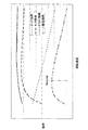
図4は、油圧システム1の効率について説明するための図であり、バックアップ用油圧ポンプ18、電動モータ19、及びドライバ21におけるバックアップ用油圧ポンプ18の回転速度に対するそれぞれの効率の変化を例示する図である。尚、図4では、バックアップ用油圧ポンプ18におけるその回転速度に対する効率(ポンプ効率)の変化をピッチの細かい破線で図示している。また、同図では、電動モータ19におけるバックアップ用油圧ポンプ18の回転速度に対する効率(モータ効率)の変化を上記ポンプ効率の変化を示す破線よりもピッチの粗い破線で図示している。また、同図では、ドライバ21におけるバックアップ用油圧ポンプ18の回転速度に対する効率(ドライバ効率)の変化を実線で図示している。また、同図では、バックアップ用油圧ポンプ18の効率と電動モータ19の効率とドライバ21の効率とを乗じた積として得られる総合効率(即ち、「総合効率」=「ポンプ効率」×「モータ効率」×「ドライバ効率」)の変化(総合効率のバックアップ用油圧ポンプ18の回転速度に対する変化)を一点鎖線で図示している。また、同図については、効率及び回転速度についての具体的な値の表記を省略して模式的に示した図として図示している。
FIG. 4 is a diagram for explaining the efficiency of the
図4に示すように、バックアップ用油圧ポンプ18の回転速度に対して変化する総合効率は、回転速度がNconst(図4にて二点鎖線Nconstで示す回転速度)のときにおいて、最大値となっている。そして、ドライバ21がバックアップ用油圧ポンプ18を回転駆動する際の前述の所定の一定回転速度は、Nconstに設定されている。即ち、油圧システム1においては、バックアップ用油圧ポンプ18、電動モータ19及びドライバ21におけるバックアップ用油圧ポンプ18の回転速度に対するそれぞれの効率の変化に基づいて、前述の総合効率が最大値となるように、上記の所定の一定回転速度がNconstに設定されている。
As shown in FIG. 4, the total efficiency that changes with respect to the rotational speed of the backup
また、本実施形態では、電動モータ19がブラシレスモータとして構成されている形態を例示しているが、この形態においては、ドライバ21は、例えば、電動モータ19におけるステータコイルの各相に対して電源ユニット20からの直流電流を順次切り替えて通電する制御を行う電子回路等として設けられる。尚、電動モータ19は、ブラシ付直流モータとして構成されていてもよく、また、誘導モータや同期モータのような交流モータとして構成されていてもよい。電動モータ19がブラシ付直流モータとして構成される場合は、ドライバ21は、例えば、電動モータ19の駆動電圧を変化させて電動モータ19を一定回転速度(Nconst)で回転させるように駆動する電子回路として設けられる。また、電動モータ19が誘導モータや同期モータのような交流モータとして構成される場合は、ドライバ21は、例えば、電動モータ19の回転磁界の周波数を変化させて電動モータ19を一定回転速度(Nconst)で回転させるように駆動するインバータ回路として設けられる。
In the present embodiment, the
次に、油圧システム1の作動について説明する。尚、油圧システム1の作動については、上述した油圧システム1の構成についての説明と同様に、第1機体側油圧源104に接続された油圧システム1についてのみ説明し、第2機体側油圧源105に接続された油圧システム1の作動については同様であるため説明を省略する。
Next, the operation of the
第1機体側油圧源104の機能の喪失及び低下が発生していない状態では、バックアップ用油圧ポンプ18の運転は行われない。この状態では、アクチュエータ14aに対しては、制御弁17aを介して第1油圧供給源104からの圧油が油室(15a、15b)の一方に供給され、油室(15a、15b)の他方から油が排出されて制御弁17aを介してリザーバ回路106に戻されることになる。また、アクチュエータコントローラ11aからの指令信号に基づいて制御弁17aの接続状態が切り替えられることで、圧油の供給及び油の排出が行われる油室(15a、15b)の切り替えが行われ、アクチュエータ14aが作動してエレベータ103が駆動される。
In a state where the function loss and deterioration of the first aircraft-side
一方、第1機体側油圧源104の機能の喪失及び低下が発生すると、フライトコントローラ12からの指令信号に基づいて、可変周波数電源108から供給されて電源ユニット20で整流されて更にドライバ21を介して供給される電力によって電動モータ19の運転が開始され、バックアップ用油圧ポンプ18が起動されてその運転が開始される。そして、ドライバ21の制御によって電動モータ19が所定の一定回転速度(Nconst)で回転するように駆動される。これにより、油圧システム1は、バックアップ用油圧ポンプ18の効率と電動モータ19の効率とドライバ21の効率との積として得られる総合効率が最大となる状態で作動することになる。
On the other hand, when the loss of function of the first airframe side
また、バックアップ用油圧ポンプ18の運転が開始されると、アクチュエータ14aに対しては、制御弁17aを介してバックアップ用油圧ポンプ18からの圧油が油室(15a、15b)の一方に供給され、油室(15a、15b)の他方から油が排出されて制御弁17aを介してバックアップ用油圧ポンプ18に吸い込まれて昇圧されることになる。また、アクチュエータコントローラ11aからの指令信号に基づいて制御弁17aの接続状態が切り替えられることで、圧油の供給及び油の排出が行われる油室(15a、15b)の切り替えが行われ、アクチュエータ14aが作動してエレベータ103が駆動される。
When the operation of the backup
以上説明したように、油圧システム1によると、機体側油圧源(104、105)の機能の喪失又は低下が発生した場合であっても、バックアップ用油圧ポンプ18から圧油が供給され、アクチュエータ14aを駆動することができる。一方、バックアップ用油圧ポンプ18を駆動する電動モータ19へ供給されることになる電力は、航空機100に搭載された発電用エンジンの回転速度変化に応じて電源周波数が変化する可変周波数電源108から供給される。
As described above, according to the
しかしながら、油圧システム1では、可変周波数電源108からの電力が電源ユニット20で整流され、更に、ドライバ21が、バックアップ用油圧ポンプ18を所定の一定回転速度(Nconst)で回転させるように電動モータ19を駆動する。そして、この所定の一定回転速度(Nconst)は、バックアップ用油圧ポンプ18、電動モータ19、及びドライバ21におけるバックアップ用油圧ポンプ18の回転速度に対するそれぞれの効率の変化に基づいて、それぞれの効率を乗じた積として得られる総合効率が最大値となるように、設定されている。このため、バックアップ用油圧ポンプ18、電動モータ19、及びドライバ21を含む油圧システム1全体として、最も効率の良い運転状態を維持することができ、油圧システム1における発熱によるエネルギーロスを最も少なくすることができる。これにより、油圧システム1における発熱量を最も低減することができ、油圧システム1全体の温度上昇を抑制することができる。また、これに伴い、油圧システム1において使用される油の温度上昇も抑制することができる。
However, in the
従って、本実施形態によると、機体側油圧源(104、105)の機能の喪失時又は低下時であってもアクチュエータ14aを駆動可能であるとともに、システム全体の温度上昇と使用される油の温度上昇とを抑制することができる、航空機アクチュエータの油圧システム1を提供することができる。
Therefore, according to the present embodiment, the
また、油圧システム1によると、電動モータ19、バックアップ用油圧ポンプ18、等を備えて構成される油圧装置13が水平尾翼102の内部に配置される。このため、油圧装置13が、アクチュエータ14aにより近い領域である水平尾翼102の内部に設置されることになる。このため、油圧装置13を含む油圧システム1の小型化及び軽量化を図ることができ、航空機100の軽量化に寄与することができる。尚、エレベータ以外の舵面に対応して油圧システムが構成される場合であっても、同様に、対応する翼の内部に油圧装置が配置されることで、その油圧装置を含む油圧システムの小型化及び軽量化を図ることができる。
Further, according to the
以上、本発明の実施形態について説明したが、本発明は、上述した実施形態に限られるものではなく、特許請求の範囲に記載した限りにおいて様々に変更して実施することができる。例えば、エルロン等のエレベータ以外の舵面を駆動するアクチュエータを有するとともにこのアクチュエータに対して圧油を供給する航空機アクチュエータの油圧システムを実施してもよい。また、航空機アクチュエータの油圧システムと機体側油圧源とを接続する油圧回路形態については、種々変更して実施してもよい。また、図4として油圧システムの効率について説明するために示した図は例示であり、この例に限らず、本発明を実施することができる。即ち、ドライバがバックアップ用油圧ポンプを回転駆動する際の所定の一定回転速度が、バックアップ用油圧ポンプ、電動モータ及びドライバにおけるバックアップ用油圧ポンプの回転速度に対するそれぞれの効率の変化に基づいて、それらの効率の積である総合効率が最大値となるように、設定されていればよい。 The embodiments of the present invention have been described above. However, the present invention is not limited to the above-described embodiments, and various modifications can be made as long as they are described in the claims. For example, an aircraft actuator hydraulic system that has an actuator for driving a control surface other than an elevator such as an aileron and supplies pressure oil to the actuator may be implemented. The hydraulic circuit configuration for connecting the aircraft actuator hydraulic system and the fuselage side hydraulic power source may be variously changed. Moreover, the figure shown in order to demonstrate the efficiency of a hydraulic system as FIG. 4 is an illustration, and this invention can be implemented not only in this example. That is, the predetermined constant rotation speed when the driver drives the backup hydraulic pump to rotate is determined based on the change in efficiency with respect to the rotation speed of the backup hydraulic pump, the electric motor, and the backup hydraulic pump in the driver. It may be set so that the total efficiency, which is the product of the efficiency, becomes the maximum value.
本発明は、航空機の舵面を駆動する油圧作動式のアクチュエータを有するとともにこのアクチュエータに対して圧油を供給する、航空機アクチュエータの油圧システムとして、広く適用することができるものである。 The present invention can be widely applied as an aircraft actuator hydraulic system having a hydraulically operated actuator for driving a control surface of an aircraft and supplying pressure oil to the actuator.
1 航空機アクチュエータの油圧システム
14a アクチュエータ
18 バックアップ用油圧ポンプ
19 電動モータ
20 電源ユニット
21 ドライバ
100 航空機
103 エレベータ(舵面)
104 第1機体側油圧源(機体側油圧源)
105 第2機体側油圧源(機体側油圧源)
108 可変周波数電源
DESCRIPTION OF
104 Airframe side hydraulic power source (airframe side hydraulic power source)
105 Second body side hydraulic power source (airframe side hydraulic power source)
108 Variable frequency power supply
Claims (2)
前記バックアップ用油圧ポンプを駆動する電動モータは、前記機体側油圧源の機能の喪失又は低下に関わらず、前記航空機が着陸姿勢に入った段階においても、前記バックアップ用油圧ポンプを駆動することを特徴とする、航空機アクチュエータの油圧システム。 By the pressure oil from the installed machine side hydraulic pressure source to the body side of the aircraft is supplied, together with a hydraulically operated actuators that drive the control surfaces of the aircraft, with respect to the actuator, the loss or reduction of the aircraft central hydraulic power source function with a variable displacement hydraulic pump for backup that can supply pressure oil when they occur, a hydraulic system for aircraft actuators,
Electric motor for driving a hydraulic pump for the backup, wherein regardless of the loss or decrease in the aircraft central hydraulic power source function, even at the stage where the aircraft has entered the landing attitude, characterized by driving the hydraulic pump for the backup And the aircraft actuator hydraulic system.
Priority Applications (1)
| Application Number | Priority Date | Filing Date | Title |
|---|---|---|---|
| JP2014203580A JP5964912B2 (en) | 2014-10-02 | 2014-10-02 | Aircraft actuator hydraulic system |
Applications Claiming Priority (1)
| Application Number | Priority Date | Filing Date | Title |
|---|---|---|---|
| JP2014203580A JP5964912B2 (en) | 2014-10-02 | 2014-10-02 | Aircraft actuator hydraulic system |
Related Parent Applications (1)
| Application Number | Title | Priority Date | Filing Date |
|---|---|---|---|
| JP2010120328A Division JP2011247334A (en) | 2010-05-26 | 2010-05-26 | Hydraulic system for aircraft actuator |
Publications (3)
| Publication Number | Publication Date |
|---|---|
| JP2015028387A JP2015028387A (en) | 2015-02-12 |
| JP2015028387A5 JP2015028387A5 (en) | 2015-04-30 |
| JP5964912B2 true JP5964912B2 (en) | 2016-08-03 |
Family
ID=52492170
Family Applications (1)
| Application Number | Title | Priority Date | Filing Date |
|---|---|---|---|
| JP2014203580A Expired - Fee Related JP5964912B2 (en) | 2014-10-02 | 2014-10-02 | Aircraft actuator hydraulic system |
Country Status (1)
| Country | Link |
|---|---|
| JP (1) | JP5964912B2 (en) |
Families Citing this family (2)
| Publication number | Priority date | Publication date | Assignee | Title |
|---|---|---|---|---|
| US10337776B2 (en) * | 2017-09-19 | 2019-07-02 | The Boeing Company | Refrigeration system having valves and valve control actuators |
| CN111056044B (en) * | 2019-12-27 | 2022-08-19 | 中国航空工业集团公司沈阳飞机设计研究所 | Airplane control surface double-hydraulic servo system detection method |
Family Cites Families (5)
| Publication number | Priority date | Publication date | Assignee | Title |
|---|---|---|---|---|
| JP2003090288A (en) * | 1998-04-03 | 2003-03-28 | Ebara Corp | Diagnosing system for fluid machine |
| JP2002349513A (en) * | 2001-05-28 | 2002-12-04 | Teijin Seiki Co Ltd | Actuation system |
| JP2002310071A (en) * | 2002-02-25 | 2002-10-23 | Hitachi Ltd | Refrigerant compressor |
| JP4841848B2 (en) * | 2005-02-22 | 2011-12-21 | メタウォーター株式会社 | Optimal pump operation method, information processing system, optimal pump operation program, optimal flow distribution method for multiple pumps |
| JP4515433B2 (en) * | 2006-10-12 | 2010-07-28 | ナブテスコ株式会社 | Actuation system |
-
2014
- 2014-10-02 JP JP2014203580A patent/JP5964912B2/en not_active Expired - Fee Related
Also Published As
| Publication number | Publication date |
|---|---|
| JP2015028387A (en) | 2015-02-12 |
Similar Documents
| Publication | Publication Date | Title |
|---|---|---|
| JP2011247334A (en) | Hydraulic system for aircraft actuator | |
| JP5658117B2 (en) | Aircraft actuator hydraulic system | |
| JP5666233B2 (en) | Aircraft actuator hydraulic system | |
| JP5905294B2 (en) | Aircraft actuator hydraulic system | |
| JP5503431B2 (en) | Aircraft actuator hydraulic system | |
| JP5603651B2 (en) | Aircraft actuator hydraulic system | |
| US9670917B2 (en) | Aircraft motor drive control apparatus and aircraft actuator hydraulic system | |
| JP5784313B2 (en) | Motor control device and motor control system | |
| JP2013147049A (en) | Aircraft actuator hydraulic system | |
| WO2010097596A1 (en) | Hydraulic actuator | |
| JP5132674B2 (en) | Modular fuel supply system for gas turbine | |
| JP5964912B2 (en) | Aircraft actuator hydraulic system | |
| CN107640313B (en) | Aircraft control surface system and method for positioning control surface | |
| EP3067252A1 (en) | Hydraulic system | |
| US20180208299A1 (en) | Actuator in a landing gear system of an aircraft | |
| JP2011231886A (en) | Hydraulic apparatus for aircraft actuator | |
| CN105776046A (en) | Combined winch hydraulic system and crane using same | |
| EP2657499B1 (en) | Fluid supply device | |
| EP3960631B1 (en) | Aircraft equipped with a distributed propulsion system having suction and pressure fans | |
| JP5844164B2 (en) | Airborne motor drive control device | |
| JP2015028387A5 (en) | ||
| EP3453892A1 (en) | Electric hydraulic actuation system for a safety critical application | |
| JP2019008558A (en) | Hydraulic actuator and pressure control method of hydraulic actuator | |
| JP2016176601A (en) | Hydraulic system of aircraft actuator |
Legal Events
| Date | Code | Title | Description |
|---|---|---|---|
| A621 | Written request for application examination |
Free format text: JAPANESE INTERMEDIATE CODE: A621 Effective date: 20141104 |
|
| A521 | Request for written amendment filed |
Free format text: JAPANESE INTERMEDIATE CODE: A523 Effective date: 20150313 |
|
| RD03 | Notification of appointment of power of attorney |
Free format text: JAPANESE INTERMEDIATE CODE: A7423 Effective date: 20150413 |
|
| RD04 | Notification of resignation of power of attorney |
Free format text: JAPANESE INTERMEDIATE CODE: A7424 Effective date: 20150415 |
|
| A977 | Report on retrieval |
Free format text: JAPANESE INTERMEDIATE CODE: A971007 Effective date: 20150918 |
|
| A131 | Notification of reasons for refusal |
Free format text: JAPANESE INTERMEDIATE CODE: A131 Effective date: 20151006 |
|
| A521 | Request for written amendment filed |
Free format text: JAPANESE INTERMEDIATE CODE: A523 Effective date: 20151204 |
|
| TRDD | Decision of grant or rejection written | ||
| A01 | Written decision to grant a patent or to grant a registration (utility model) |
Free format text: JAPANESE INTERMEDIATE CODE: A01 Effective date: 20160628 |
|
| A61 | First payment of annual fees (during grant procedure) |
Free format text: JAPANESE INTERMEDIATE CODE: A61 Effective date: 20160630 |
|
| R150 | Certificate of patent or registration of utility model |
Ref document number: 5964912 Country of ref document: JP Free format text: JAPANESE INTERMEDIATE CODE: R150 |
|
| R250 | Receipt of annual fees |
Free format text: JAPANESE INTERMEDIATE CODE: R250 |
|
| R250 | Receipt of annual fees |
Free format text: JAPANESE INTERMEDIATE CODE: R250 |
|
| R250 | Receipt of annual fees |
Free format text: JAPANESE INTERMEDIATE CODE: R250 |
|
| LAPS | Cancellation because of no payment of annual fees |