JP5964524B1 - Support for photographic equipment - Google Patents
Support for photographic equipment Download PDFInfo
- Publication number
- JP5964524B1 JP5964524B1 JP2015563038A JP2015563038A JP5964524B1 JP 5964524 B1 JP5964524 B1 JP 5964524B1 JP 2015563038 A JP2015563038 A JP 2015563038A JP 2015563038 A JP2015563038 A JP 2015563038A JP 5964524 B1 JP5964524 B1 JP 5964524B1
- Authority
- JP
- Japan
- Prior art keywords
- sleeve
- plate
- locking
- longitudinal axis
- support
- Prior art date
- Legal status (The legal status is an assumption and is not a legal conclusion. Google has not performed a legal analysis and makes no representation as to the accuracy of the status listed.)
- Active
Links
- 238000003780 insertion Methods 0.000 claims description 2
- 230000037431 insertion Effects 0.000 claims description 2
- 230000009471 action Effects 0.000 description 5
- 238000000034 method Methods 0.000 description 4
- 230000008859 change Effects 0.000 description 3
- 230000004048 modification Effects 0.000 description 3
- 238000012986 modification Methods 0.000 description 3
- 230000000694 effects Effects 0.000 description 2
- 229910000842 Zamak Inorganic materials 0.000 description 1
- 239000000956 alloy Substances 0.000 description 1
- 229910045601 alloy Inorganic materials 0.000 description 1
- 230000008878 coupling Effects 0.000 description 1
- 238000010168 coupling process Methods 0.000 description 1
- 238000005859 coupling reaction Methods 0.000 description 1
- 230000007423 decrease Effects 0.000 description 1
- 230000002452 interceptive effect Effects 0.000 description 1
- 239000007769 metal material Substances 0.000 description 1
- 238000007634 remodeling Methods 0.000 description 1
- 230000007704 transition Effects 0.000 description 1
Images


Classifications
-
- F—MECHANICAL ENGINEERING; LIGHTING; HEATING; WEAPONS; BLASTING
- F16—ENGINEERING ELEMENTS AND UNITS; GENERAL MEASURES FOR PRODUCING AND MAINTAINING EFFECTIVE FUNCTIONING OF MACHINES OR INSTALLATIONS; THERMAL INSULATION IN GENERAL
- F16M—FRAMES, CASINGS OR BEDS OF ENGINES, MACHINES OR APPARATUS, NOT SPECIFIC TO ENGINES, MACHINES OR APPARATUS PROVIDED FOR ELSEWHERE; STANDS; SUPPORTS
- F16M11/00—Stands or trestles as supports for apparatus or articles placed thereon ; Stands for scientific apparatus such as gravitational force meters
- F16M11/02—Heads
- F16M11/04—Means for attachment of apparatus; Means allowing adjustment of the apparatus relatively to the stand
- F16M11/041—Allowing quick release of the apparatus
-
- F—MECHANICAL ENGINEERING; LIGHTING; HEATING; WEAPONS; BLASTING
- F16—ENGINEERING ELEMENTS AND UNITS; GENERAL MEASURES FOR PRODUCING AND MAINTAINING EFFECTIVE FUNCTIONING OF MACHINES OR INSTALLATIONS; THERMAL INSULATION IN GENERAL
- F16M—FRAMES, CASINGS OR BEDS OF ENGINES, MACHINES OR APPARATUS, NOT SPECIFIC TO ENGINES, MACHINES OR APPARATUS PROVIDED FOR ELSEWHERE; STANDS; SUPPORTS
- F16M11/00—Stands or trestles as supports for apparatus or articles placed thereon ; Stands for scientific apparatus such as gravitational force meters
- F16M11/02—Heads
- F16M11/16—Details concerning attachment of head-supporting legs, with or without actuation of locking members thereof
-
- F—MECHANICAL ENGINEERING; LIGHTING; HEATING; WEAPONS; BLASTING
- F16—ENGINEERING ELEMENTS AND UNITS; GENERAL MEASURES FOR PRODUCING AND MAINTAINING EFFECTIVE FUNCTIONING OF MACHINES OR INSTALLATIONS; THERMAL INSULATION IN GENERAL
- F16M—FRAMES, CASINGS OR BEDS OF ENGINES, MACHINES OR APPARATUS, NOT SPECIFIC TO ENGINES, MACHINES OR APPARATUS PROVIDED FOR ELSEWHERE; STANDS; SUPPORTS
- F16M11/00—Stands or trestles as supports for apparatus or articles placed thereon ; Stands for scientific apparatus such as gravitational force meters
- F16M11/20—Undercarriages with or without wheels
- F16M11/24—Undercarriages with or without wheels changeable in height or length of legs, also for transport only, e.g. by means of tubes screwed into each other
- F16M11/26—Undercarriages with or without wheels changeable in height or length of legs, also for transport only, e.g. by means of tubes screwed into each other by telescoping, with or without folding
- F16M11/28—Undercarriages for supports with one single telescoping pillar
-
- F—MECHANICAL ENGINEERING; LIGHTING; HEATING; WEAPONS; BLASTING
- F16—ENGINEERING ELEMENTS AND UNITS; GENERAL MEASURES FOR PRODUCING AND MAINTAINING EFFECTIVE FUNCTIONING OF MACHINES OR INSTALLATIONS; THERMAL INSULATION IN GENERAL
- F16M—FRAMES, CASINGS OR BEDS OF ENGINES, MACHINES OR APPARATUS, NOT SPECIFIC TO ENGINES, MACHINES OR APPARATUS PROVIDED FOR ELSEWHERE; STANDS; SUPPORTS
- F16M11/00—Stands or trestles as supports for apparatus or articles placed thereon ; Stands for scientific apparatus such as gravitational force meters
- F16M11/20—Undercarriages with or without wheels
- F16M11/24—Undercarriages with or without wheels changeable in height or length of legs, also for transport only, e.g. by means of tubes screwed into each other
- F16M11/26—Undercarriages with or without wheels changeable in height or length of legs, also for transport only, e.g. by means of tubes screwed into each other by telescoping, with or without folding
- F16M11/32—Undercarriages for supports with three or more telescoping legs
-
- F—MECHANICAL ENGINEERING; LIGHTING; HEATING; WEAPONS; BLASTING
- F16—ENGINEERING ELEMENTS AND UNITS; GENERAL MEASURES FOR PRODUCING AND MAINTAINING EFFECTIVE FUNCTIONING OF MACHINES OR INSTALLATIONS; THERMAL INSULATION IN GENERAL
- F16M—FRAMES, CASINGS OR BEDS OF ENGINES, MACHINES OR APPARATUS, NOT SPECIFIC TO ENGINES, MACHINES OR APPARATUS PROVIDED FOR ELSEWHERE; STANDS; SUPPORTS
- F16M2200/00—Details of stands or supports
- F16M2200/02—Locking means
- F16M2200/025—Locking means for translational movement
Landscapes
- Engineering & Computer Science (AREA)
- General Engineering & Computer Science (AREA)
- Mechanical Engineering (AREA)
- Studio Devices (AREA)
- Accessories Of Cameras (AREA)
- Coating Of Shaped Articles Made Of Macromolecular Substances (AREA)
- Packaging Of Machine Parts And Wound Products (AREA)
Abstract
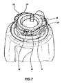
ビデオ写真装置用支持体(1)は、孔(5)を画定するクロスメンバー(2)と、縦軸(Z)に沿って前記孔(5)内を摺動するシャフト(21)を有する支柱(6)と、プレート(7)に1台のビデオ写真装置を係合するための係合装置(8)を設けたプレート(7)と、縦軸(Z)に沿って伸び、前記支柱(6)の係合部(23)を収容可能な中空のスリーブ(10)とを備え、前記プレート(7)が、前記スリーブ(10)内に前記支柱(6)の前記係合部(23)を固定するために移動されるロック装置(13、18、25、26、10c)を更に備える。【選択図】図1The support (1) for a video photographic apparatus has a cross member (2) that defines a hole (5), and a column having a shaft (21) that slides in the hole (5) along the longitudinal axis (Z). (6), a plate (7) provided with an engagement device (8) for engaging a single video photographic device with the plate (7), and the strut ( 6) a hollow sleeve (10) capable of accommodating the engaging portion (23) of the plate, and the plate (7) is placed in the sleeve (10) in the engaging portion (23) of the column (6). It is further provided with a locking device (13, 18, 25, 26, 10c) which is moved to fix the. [Selection] Figure 1
Description
本発明は、主請求項のプリアンブルに記載されている特徴を有するタイプのビデオ写真機材などのための支持体に関する。 The present invention relates to a support for video photographic equipment of the type having the characteristics described in the preamble of the main claim.
写真、テレビおよび映画撮影の分野で、記録装置を指向可能な方法で支持するために、三脚、スタンドなどのような支持体を使用することが広く知られている。 In the field of photography, television and cinematography, it is widely known to use a support such as a tripod, stand, etc. to support the recording device in a directional manner.
このような技術分野において、前記支持体は、3つ以上の伸縮自在な脚部が既知の方法で接続されたクロスメンバーと、このクロスメンバーに画定された孔に軸方向に摺動自在な1つの支柱を含んでいる。
In such a technical field, the support body includes a cross member in which three or more stretchable legs are connected by a known method, and an axially
この支柱の一端には、支持される装置を支えることを意図したプレートが装着されている。 At one end of the column is a plate intended to support the device to be supported.
脚部は通常伸縮自在で、クロスメンバーに対する様々な開角度(opening angle)に位置決めしてロックすることができ、一方、クロスメンバーの孔内を軸方向に支柱を摺動させることによってプレートの高さを変動させることができ、それによって、様々な高さに位置する対象を撮影するために、プレートと連動して装置の高さを変動させることができる。 The legs are usually telescopic and can be positioned and locked at various opening angles with respect to the cross member, while the plates are raised by sliding the struts axially through the holes in the cross member. The height of the device can be varied in conjunction with the plate to image objects located at various heights.
この既知の支持体の欠点は、クロスメンバーの下に突出した支柱の部分と支持体の支持面との間の干渉により生じるが、この干渉によって例えば地面に近い高さで撮影するためにビデオ写真機材を非常に低いポイントに位置付けることが妨げられる。 The disadvantage of this known support is caused by the interference between the part of the column projecting under the cross member and the support surface of the support, which makes it possible to take a video photograph for shooting at a height close to the ground, for example. Positioning the equipment at a very low point is impeded.
この欠点は、同出願人による国際公開公報WO2007/125082に記述された支持体によって克服されている。 This drawback has been overcome by the support described in the applicant's international publication WO 2007/125082.
国際公開公報WO2007/125082の支持体は、三脚の支持脚部がヒンジで取り付けられたクロスメンバーと、このクロスメンバーに設けられた孔で摺動することができる支柱とを含み、この支柱の一端にはビデオ写真機材を支えることを意図したプレートが設けられ、この支柱の対向する他端にはキャップが設けられている。プレートとキャップは支柱から取り外すことができるように脱着可能な固定手段で支柱に取り付けられ、クロスメンバーの対向する両端に取り付けられる。 The support body of International Publication No. WO2007 / 125082 includes a cross member to which a support leg portion of a tripod is attached by a hinge, and a support column that can slide in a hole provided in the cross member, and one end of the support column Is provided with a plate intended to support video photographic equipment, and a cap is provided at the other opposite end of the column. The plate and the cap are attached to the column by a detachable fixing means so that the plate and the cap can be removed from the column, and are attached to opposite ends of the cross member.
例えば、地面または地面近くに置かれた対象を撮影するために支持体の垂直の空間的な制約条件を低減することが望ましいとき、操作者は支柱からキャップとプレートを分離し、クロスメンバーの孔から支柱を取り外し、次いでクロスメンバーに直接プレートとキャップを取り付ける。 For example, when it is desirable to reduce the vertical spatial constraints of the support to image an object placed on or near the ground, the operator can separate the cap and plate from the column and the cross member hole Remove the strut from and then attach the plate and cap directly to the cross member.
この支持体は上述の問題を解決するが、支持体を、支柱を備えた構造から、短い構造すなわち支柱のない構造に改造するのに必要な操作が面倒であるという欠点がある。 Although this support solves the above-mentioned problems, it has the disadvantage that the operations required to convert the support from a structure with a support to a short structure, ie, a structure without a support, are cumbersome.
上述の改造を行なうために、頭部が取り付けられたプレートを分離する必要があり、したがって、ビデオ写真機材を支柱から分離する必要があり、孔から支柱を取り外した後、再度クロスメンバーにプレートを直接取り付ける必要がある。したがって、頭部とビデオ写真機材を破損するリスクがある。 In order to make the above modifications, it is necessary to separate the plate with the head attached, so the video photographic equipment must be separated from the column, and after removing the column from the hole, the plate is again placed on the cross member. Must be installed directly. Therefore, there is a risk of damaging the head and video photographic equipment.
本発明の課題は、引用された先行技術文献に述べられた限界を構造上機能的に克服することを意図した、ビデオ写真機材の支持体を提供することである。 The object of the present invention is to provide a support for video photographic equipment intended to structurally and functionally overcome the limitations described in the cited prior art documents.
この問題と以下に明らかになる他の問題は本発明によって検討され、添付されたクレームに従って製作された支持体によって解決される。 This and other problems that will become apparent below are addressed by the present invention and are solved by a support made in accordance with the appended claims.
本発明の特徴と利点は、添付図面を参照して非限定例として示される、本発明の好ましい、且つ非排他的な実施の形態の以下の詳細な説明から明らかになる。 The features and advantages of the present invention will become apparent from the following detailed description of the preferred and non-exclusive embodiments of the invention, given as non-limiting examples with reference to the accompanying drawings.
これらの図面はビデオ写真機材用の支持三脚1を示し、この支持体は本発明に従って構成されている。
These drawings show a
三脚1は、支持脚部4がヒンジで取り付けられた各々の領域において、ヒンジで動く3つの延長部品3を画定するように形成されるクロスメンバー2を含んでいる。
The
支持脚部4は、長さに関して伸縮自在で、長さを既知の方法で調整でき、三脚の高さおよび/またはその空間的な制約条件を変更することができる。
The
クロスメンバー2は、スライド式係合によって三脚1の支柱6を収容するように意図されたスライド孔5を画定するように形成される。支柱6は孔5内を孔5の縦軸Zに沿って摺動することができる。
The cross member 2 is formed so as to define a slide hole 5 intended to receive the column 6 of the
クロスメンバー2は、支柱6の軸Zに沿った動きをロックする/アンロックするために、三脚1のユーザーによって当該分野でそれ自体が既知の方法で動かされる、クランプリング20を更に含んでいる。
The cross member 2 further includes a
三脚1は、係合装置を備えたプレート7を更に含み、例えば、このプレート7で1つのビデオ写真機材(図示せず)を係合するために、縦軸Zに対して同軸上にある、実質的に円筒形状の係合ねじ8を含んでいる。
The
プレート7は、ビデオ写真機材と接して支えることを意図した当接面Sと、中空のスリーブ10が連結される連結部9を更に含んでいる。スリーブ10はプレート7の連結部9から当接面Sの反対方向へと伸びている。
The plate 7 further includes a contact surface S intended to support and support the video photographic equipment, and a connecting
スリーブ10は、三脚1の使用中またはスリーブ10が支柱6または孔5それ自体に取り付けられた状態で、実質的に孔5の縦軸Zに相当する縦軸に沿って伸びている。したがって、この軸は、以下、簡潔を期して同じ参照番号で示される。
The
スリーブ10は、使用中、実質的に孔5の縦軸Zに相当する縦軸に沿って伸びる、管状の筒状体を含んでいる。
The
スリーブ10は、以下に詳細に説明されるように、プレート7に支柱6を連結するために、支柱6を摺動式に支えるように形成される。スリーブ10は、その外表面10aに、間隔を置いて周囲に配置された複数の孔を備えている。示された変形例では、ほぼ120°の角度間隔を置いて離れて配置された、3つの孔12を備えている。
The
孔12は、以下に詳細に説明されるように、プレート7に設けられたロック装置13と協働するように形成され、プレート7と支柱6を連結/分離するために、スリーブ10に支柱6をロックまたはスリーブ10から支柱6をアンロックするように配置されている。
The
ロック装置13は、連結部9の外側に配置され、三脚のユーザーが、スリーブ10に支柱6をロックまたはスリーブ10から支柱6をアンロックするために、図1の矢印Gの両方向に回転できるロッキングリングナット14を含んでいる。ロック装置13は、スリーブ10に支柱6をロックまたはスリーブ10から支柱6をアンロックするために、ロッキングリングナット14によって移動させることができる複数のロッキングブロック18を更に含んでいる。
The
図示されない更なる変形例では、支持体は、スリーブ10に支柱6をロックまたはスリーブ10から支柱6をアンロックするために、リングナットとは異なるロッキングブロックを移動させるのに適切なロック装置13または別の適切なロック手段を備えている。ロック装置13として、例えば偏心レバー、ノブ、ねじなどを使用することができる。
In a further variant, not shown, the support is a
スリーブ10の孔12と対応する数のロッキングブロック18が設けられ、各ロッキングブロックは対応する孔12内に摺動する方法で支えられるように形成されている。
A number of
図示された変形例では、周囲に等距離で配置された3つのロッキングブロック18が設けられている。
In the illustrated modification, there are three
各ロッキングブロック18は金属材料、例えばZamak合金から製作される。
Each
三脚1の他の変形例(図示せず)では、異なる数のロッキングブロックが備えられてもよいが、等距離が好ましい。
In other variants (not shown) of the
ロッキングブロック18は格納形態Xとロック形態Yとの間で移動可能である。以下に詳細に説明されるように、格納形態Xは図3に示され、格納形態Xにおいてロッキングブロック18は、ロッキングリングナット14とスリーブ10との間で画定されるハウジング27に配置され、この形態において支柱6はスリーブ10に対して移動させることができる。一方、ロック形態Yは図2に示され、ロック形態Yにおいて各ブロック18は対応する孔12に挿入され、それによってスリーブ10の内側に突出し、支柱6と干渉し、支柱6をスリーブ10にロックする。
The
ロック形態Yにおいて、ロッキングブロック18は、スリーブ10に支柱6をロックするために、この支柱6に備えられた対応するロック対向手段と協働し、ロック装置13のロック手段を構成している。
In the locking configuration Y, the
ロック装置13は、ロッキングブロック18と関連付けてハウジング27の内側にロッキングブロック18を押すように配置され、支柱6と干渉しないようにする押込装置を更に含んでいる。
The
図示された変形例において、押込装置は3つの板ばね29を含み、各板ばね29は、対応するロッキングブロック18と関連付けられ、ハウジング27にロッキングブロック18を押し込むことができる押す力を各ロッキングブロック18に適用するように配置されている。
In the illustrated variant, the pushing device includes three leaf springs 29, each leaf spring 29 being associated with a
図示されない他の変形例において、複数の板ばねまたは単一の板ばねとは異なる押込装置が設けられてもよい。 In other variations not shown, a pushing device different from a plurality of leaf springs or a single leaf spring may be provided.
ロッキングリングナット14は、ロッキングリングナット14を回転させるためにユーザーがしっかり握れるようなハンドル14aを含み、ロッキングリングナット14から、スリーブ10の周囲に外側から配置される作動延長部(actuation extension piece)15が、プレート7の反対側に伸びている。作動延長部15は、スリーブ10の縦軸Zに対して傾斜した方向に配置された押し表面(pushing surface)16を含み、押し表面16はロッキングブロック18と接してこれを支えるので、ロッキングブロック18は押し表面16に対して摺動できる。押し表面16は、好ましくはスリーブ10の縦軸Zに対して15°〜30°の角度αに配置され、ロッキングブロック18のための摺動コーンを構成する。
The locking
押し表面16は、ロッキングリングナット14から離れる方向へスリーブ10に向かって収斂するように配置され、押し表面16によってロッキングブロック18に加えられた圧力が、以下に詳細に説明されるように、ロッキングリングナット14から離れる方向または矢印F2の方向に増加する。
The pushing
押し表面16が縦軸Zに対して傾斜しているので、縦軸Zに沿ってそれを移動させると、以下に詳細に説明されるように、押し表面16によってロッキングブロック18に加えられる圧力が変化する。
Since the pushing
縦軸Zに対して傾斜し、摺動自在に接してロッキングブロック18を支えるよう配置された押し表面16は、必ずしも回転ロック装置ではなく、ロッキングリングナットとは異なる形状のロック装置を設けることができる。
The pushing
ロッキングリングナット14のスリーブ10に対する回転によってロッキングリングナット14は縦軸Zに沿って移動し、回転方向に応じてプレート7の方向またはプレート7から離れる方向に移動され、したがって、ロッキングリングナット14の回転移動運動が得られる。
Due to the rotation of the locking
ロッキングリングナット14がプレート7の方へ移動されるとき、ロッキングリングナット14に固定して結合された押し表面16も、ロッキングブロック18に対して摺動しながらプレート7の方へ移動される。
When the locking
上述の通り、押し表面16は縦軸Zに対して傾斜しているので、押し表面16がプレートの方へ移動すると、ロッキングブロック18に対する押す力が増す。
As described above, since the pushing
押し表面16によってロッキングブロック18に適用される押す力は図3における矢印F2によって示されるが、その力はロッキングブロック18に対して板ばね29によって加えられる圧力と反対方向に向かい、その圧力より大きい。
The pushing force applied to the locking
したがって、ロッキングブロック18は、押し表面16を摺動し、プレート7の方へ押され、次第にハウジング27から除去され、スリーブ10に設けられた夫々の孔12に挿入され、ロック形態Yに移行する。ロック形態Yにおいて、ロッキングブロック18は、スリーブ10の内側に突出し、以下に詳細に説明されるように、支柱6をスリーブ10にロックする。
Thus, the locking
逆に、ロッキングリングナット14がロッキングリングナット14をプレート7から離れる回転方向に回転させるとき、押し表面16がプレート7から遠ざかり、ロッキングブロック18に対して摺動し、ロッキングブロック18と押し表面16の間の相対運動を引き起こし、押し表面とロッキングブロック18の間の干渉を低減する。
Conversely, when the locking
押し表面16が縦軸Zに対して傾斜しているので、ロッキングブロック18に対して押し表面16によって加えられる力は次第に減少し、ロッキングリングナット14から押し表面16が離れる。
Since the pushing
したがって、板ばね29によって加えられた圧力の影響によりロッキングブロック18が押し表面16に対して押し付けられたままなので、ロッキングブロック18は夫々の孔12から解放され、ハウジング27に次第に受け入れられ、以下に詳細に説明されるように、スリーブ10に対して支柱6のロックを解除し、格納形態Xに到達する。
Thus, because the
板ばね29は、ロッキングブロック18がハウジング27に保持されることを可能にしている。
The leaf spring 29 allows the locking
ロッキングリングナット14は、スリーブ10の周囲に配置され、クロスメンバー2のクランプリング20に接するように配置されるガスケット19を更に含んでいる。
The locking
支柱6は、支柱6の縦軸に沿って縦に伸びる管状のシャフト21を含み、三脚1の使用中または支柱6が孔5に挿入された状態で、その縦軸は実質的に孔5の縦軸Zに相当する。この縦軸は、以下に簡潔を期して同じ参照番号で示される。
The strut 6 includes a
シャフト21は、孔5内で摺動できるように構成され、支柱6をプレート7と連結するために、縦方向端部21aにスリーブ10に挿入される係合部を備えている。
The
係合部は、シャフト21内に配置され、そこに取り付けられる第1の部分23aと、スリーブ10内に摺動式に挿入される第2の部分23bと、第1の部分23aと第2の部分23bとの間に置かれ、スピゴット23をスリーブ10に挿入中に移動限界要素として作用するショルダー部23cとを備えるスピゴット23の方式で形成される。
The engaging portion is disposed in the
図示された変形例において、ショルダー部23c、シャフト21およびスリーブ10は、同じ外径D1を有している。その結果、支柱6がスリーブ10に取り付けられた状態で実質的に連続面を形成し、ひいては支柱6とプレート7を含む組立体が孔5の縦軸Zに沿って自由に摺動することができ、支柱6とスリーブ10は同様にクロスメンバー2の孔5に取り付けることができる。
In the illustrated modification, the
更なる図示されない変形例において、スリーブ10は、支柱6のシャフト21の外径D1と実質的に等しい外径D1’を有している。スリーブ10の外径D1’とシャフト21の外径D1との差は、スリーブ10の外径D1’の5〜10%が好ましい。
In a further variant not shown, the
前述のように、特に有利な変形例では、スリーブ10とシャフトが同じ外径D1を有している。
As mentioned above, in a particularly advantageous variant, the
支柱6は、孔5内で縦軸Zに沿って摺動して、プレート7とクロスメンバー2の間隔を変更することができ、または三脚1の空間的な制約条件および/またはプレート7に係合したビデオ写真機材の位置調整の高さを変更することができる。
The strut 6 can slide along the longitudinal axis Z in the hole 5 to change the spacing between the plate 7 and the cross member 2, or the spatial restriction of the
スピゴット23の第2の部分23bは、ショルダー部23cの外径D1未満の外径を有し、スリーブ10に挿入され、スリーブ10内で摺動することができる。
The
第2の部分23bの自由端24またはショルダー部23cとは反対側に、第2の部分23bは溝25を備えており、この溝25は自由端24で周囲に伸び、スリーブ10に支柱6をロックするためにプレート7のロック手段と協働するロック対向手段を構成するように形成される。
On the opposite side of the
溝25は、スリーブ10に支柱6をロックするために、押し込み式ロック法でプレート7のロッキングブロック18と連結されるように形成され、ロック位置Yにおいて、ロッキングブロック18は溝25に収容される。
The
第2の部分23bの方へ向けられたショルダー部23cの表面26は、スリーブにおいて支柱用のロック要素を構成するように形成される。この表面26は、スリーブ10に支柱6をロックするためにスリーブ10の自由端10cと協働することができる。
The
以下に詳細に説明されるように、表面26は、スリーブ10内の支柱6の摺動に対する移動限界要素として更に作用することができる。
As described in detail below, the
自由端10cと表面26は、第2ロック手段と対向手段を夫々構成し、スリーブ10に支柱6をロックするために相互に協働する。
The
自由端10cが円錐形で、一方の表面26が球状である。したがって、表面26と自由端10cとの間に線形接触が生じ、スリーブ10に支柱6をロックすることができる。
The
したがって、プレート7またはスリーブ10は、縦方向に対向する位置に設けられた第1および第2ロック手段を備え、これらのロック手段が、縦方向に対向する位置に設けられた、支柱6の対応する第1および第2ロック対向手段またはスピゴット23と協働する。
Accordingly, the plate 7 or the
したがって、スピゴット23およびスリーブ10は、その2つの相対する縦方向の両端領域において相互に固定される。
Accordingly, the
これは、実質的にスピゴット23ひいては支柱6とプレート7との間の相対的なロック作用を改善し、縦軸Zについての遊びと振動を防ぐ。
This substantially improves the relative locking action between the
これは、プレート7と係合された1台のビデオ写真機材の位置決めと、撮影画像の品質を改善する。 This improves the positioning of one video photographic equipment engaged with the plate 7 and the quality of the captured image.
ユーザーが、図2に示される作動形態Wで、すなわち支柱6により三脚1を使用したいとき、ユーザーが自由端24を連結部分9の方へ押すことにより、支柱6のシャフト21が孔5に導入され、スピゴット23がプレート7のスリーブ10に導入されるように、図3の中間作用形態W’における三脚を構成する。
When the user wants to use the
中間作用形態W’において、ロッキングブロック18はハウジング27に挿入され、スピゴット23はスリーブ10で摺動することができる。
In the intermediate working configuration W ′, the locking
ロッキングリングナット14は、プレート7の表面Sから最も遠い移動限界まで完全に広げられ、または回転される。
The locking
次いで、ユーザーは、図2の第1作用形態Wに三脚を移動させて、支柱6とプレート7をロックする準備をする。 Next, the user prepares to lock the column 6 and the plate 7 by moving the tripod to the first action form W of FIG.
これを行うために、ユーザーは、プレート7の表面Sに向かってロッキングリングナット14を移動させる方向に、縦軸Zに対してロッキングリングナット14を回転させる。
To do this, the user rotates the locking
図2の矢印Fによって示されるように、その回転は、プレート7の押し表面16に向かって運動を引き起こし、それは次いで、図3において矢印F2により示されるように、押し表面16に対して直角の方向でロッキングブロック18への押す力を次第に増加する。
As indicated by arrow F in FIG. 2, that rotation causes movement toward the pushing
押し表面16が縦軸Zに対して傾斜し、プレート7の方へ次第に押し表面16を移動させるので、ロッキングブロック18は、押す力F2の構成要素のF12の影響によってプレート7の方へ、および押す力F2の構成要素のF22の影響によってスリーブ10の内部の方へ、徐々に移動させられる。
Press the
ロッキングブロック18は、押す力F2の結果として、押し表面16に対して摺動し、プレート7の方へ移動させられ、スリーブ10の表面に設けられた孔12内に徐々に挿入され、スピゴット23の開口部24に設けられた溝25に、ロッキングブロック18が挿入され、それによって支柱6をスリーブ10にロックする、図2に示されるロック形態Yに到達する。
As a result of the pushing force F2, the locking
ロッキングブロック18が溝25に次第に導入されるとき、ロッキングブロック18の押下壁(pushing wall)18aは、プレート7の方へ誘導される溝25の壁25aと相互に作用し、プレート7の方へスピゴット23を徐々に移動させる。
As the locking
スピゴット23は、図2の矢印Fによって示された方向に、またはプレート7に向かって更に移動され、スリーブ10は、スリーブ10の自由端10cがショルダー部23cに対して接するまで移動して、スピゴット23それ自体に取り付けられる。
The
その位置において、表面26および自由端10cは押し込み式のロック方法で連結され、スピゴット23はスリーブ10にクランプされる。
In that position, the
したがって、図2の作用形態Wにおいて、支柱6またはスピゴット23と、プレート7またはスリーブ10は、軸Zに対して2つが別々に縦方向に対向位置で互いにロックされる。
Therefore, in the operation mode W of FIG. 2, the column 6 or the
作用形態Wにおいて三脚1の位置決め中に、プレート7に取り付けられた装置が任意で存在する場合でも、支柱6とプレート7の間のロックには妨げとはならず、したがって、支柱6と係合される十分に前でも後でも同様に、装置はプレート7に瞬時に取り付けられる。
During the positioning of the
プレート7の高さを調整するために、プレート7が、ひいてはそれと係合される装置についても、所望位置またはプレート7の望ましい高さに達するまで、ユーザーは縦軸Zに沿って孔5の支柱6を移動させ、したがって、孔5における所望位置に支柱6をクランプリング20によってロックする。
In order to adjust the height of the plate 7, for the device with which the plate 7 is to be engaged, and thus the desired position or the desired height of the plate 7 is reached, the user also supports the column of holes 5 along the longitudinal axis Z. 6 is moved and therefore the strut 6 is locked by the
クランプリング20は、支柱6またはスリーブ10をクロスメンバー2にクランプまたはクロスメンバー2からリリースするために、縦軸Zの周囲を回転するように配置される。
The
クランプリング20は、孔5に支柱6またはスリーブ10を合わせて支柱6またはスリーブ10をクランプするために、または支柱6またはスリーブ10が縦軸Zに沿って孔5内を移動自在になるように、支柱6またはスリーブ10をリリースするために配置された、円錐台形のクランプ表面20aを備えている。
The
クランプリング20を回転させることによって、円錐台形のクランプ表面20aは、縦軸Zに沿って移動され、結果的に半径方向寸法が変更され、したがって、支柱6またはスリーブ10をクロスメンバー2にクランプまたは/クロスメンバー2からリリースする。
By rotating the
非常に地面の近くに位置する対象を撮影したい場合、装置を所望通り配置できないような支柱6の空間的な制約条件を防ぐために、ユーザーは図6に示される第2作用位置W’’に位置する三脚1を準備する。
When it is desired to photograph an object located very close to the ground, the user is positioned at the second working position W ″ shown in FIG. 6 in order to prevent the spatial constraints of the column 6 that the device cannot be placed as desired. Prepare the
これを行うために、ユーザーは、ロッキングリングナット14に働きかけて支柱6からプレート7のロックを解除し、プレート7からロッキングリングナット14を離し、図2の矢印F1によって示された方向にそれを移動させ、図3の中間形態に三脚1を移動させる。
To do this, the user acts on the locking
押し表面16はプレート7から離され、ロッキングブロック18は押し表面16を摺動し、ロッキングリングナット14とスリーブ10との間に備えられたハウジング27に次第に導入されることによって、板ばね29によって押される溝25および孔12から離される。
The pushing
ロッキングブロック18が図3に示される格納位置Xにあるとき、スピゴット23は、もはや連結部9に対して接するように押されないため、接続面26はスリーブ10の内表面10bに干渉しない。
When the locking
したがって、ロッキングブロック18が格納位置Xに位置し、プレート7と支柱6とを分離するために、スリーブ10内で支柱6が自由に摺動し、スリーブ10から自由に回して取り外すことができる。
Accordingly, the locking
プレート7と支柱6とを分離した後、ユーザーは、クランプリング20によってロックを解除し、孔5から支柱6を引き出し、孔5から支柱6を引き離す。
After separating the plate 7 and the column 6, the user releases the lock by the
プレート7と支柱6を分離するために、ユーザーは、プレート7と係合された支柱6を最初に任意選択的に孔5から引き出し、次いでロック装置13に働きかけてもよい。
In order to separate the plate 7 and the column 6, the user may first optionally pull the column 6 engaged with the plate 7 out of the hole 5 and then work on the
その後、ユーザーは、支柱6なしで孔5にスリーブ10を挿入し、クランプリング20自体に働きかけて、ガスケット19がクランプリング20に接するまで移動させ、三脚を図6の第2作用形態W’’に位置決めすることによって孔5にスリーブ10をロックする。
Thereafter, the user inserts the
この位置において、スリーブ10の管状の筒状体は、孔5に少なくとも部分的に挿入され、孔5にスリーブ10をクランプするために、クランプリング20と相互作用する。
In this position, the tubular body of the
スリーブ10は、支柱6のシャフト21の外径と実質的に等しい外径D1’を有するので、スリーブ10は、第2作用形態W’’と第1作用形態Wの両方において支持体のロックは安定している。
Since the
クロスメンバー2の孔5にスリーブ10をロックするために、ユーザーは当該分野で既知の方法によってクランプリング20に働きかける。
To lock the
ユーザーは、縦軸Zの周囲をクランプリング20を回転させ、スリーブ10の方向へ係合表面20aを徐々に押し、スリーブ10を孔5に徐々にクランプする。
The user rotates the
また、スリーブの外径D1’とシャフトD1は実質的に相互に等しいので、第1および第2作用形態WとW’’の両方において有効なクランプを得ることが可能である。 Further, since the outer diameter D1 'of the sleeve and the shaft D1 are substantially equal to each other, it is possible to obtain an effective clamp in both the first and second operation modes W and W ".
図2,6に夫々示される三脚1の形態間の移動は、プレート7から装置を分離することなく実行できる。
Movement between the forms of the
したがって、装置に対して危険性のある損傷が予防され、三脚1を改造するための操作がスピードアップされ、位置決め操作は大いに簡潔になる。
Therefore, risky damage to the device is prevented, the operation for remodeling the
したがって、本発明は、引用された先行技術に関して上述の問題を解決する。 The present invention thus solves the above-mentioned problems with respect to the cited prior art.
Claims (13)
The sleeve (10) and the shaft (21) have substantially equal outer diameters (D1, D1 ′), and when the column (6) is attached to the sleeve (10), the hole (5 The support body according to any one of claims 1 to 12, wherein a substantially continuous surface slidable along the longitudinal axis (Z) is formed along the longitudinal axis (Z).
Applications Claiming Priority (3)
| Application Number | Priority Date | Filing Date | Title |
|---|---|---|---|
| ITPD2013A000154 | 2013-05-31 | ||
| IT000154A ITPD20130154A1 (en) | 2013-05-31 | 2013-05-31 | SUPPORT FOR PHOTOGRAPHIC EQUIPMENT |
| PCT/EP2014/061156 WO2014191507A1 (en) | 2013-05-31 | 2014-05-28 | Support for photographic apparatuses |
Publications (2)
| Publication Number | Publication Date |
|---|---|
| JP5964524B1 true JP5964524B1 (en) | 2016-08-03 |
| JP2016531307A JP2016531307A (en) | 2016-10-06 |
Family
ID=48748420
Family Applications (1)
| Application Number | Title | Priority Date | Filing Date |
|---|---|---|---|
| JP2015563038A Active JP5964524B1 (en) | 2013-05-31 | 2014-05-28 | Support for photographic equipment |
Country Status (6)
| Country | Link |
|---|---|
| US (1) | US20160116103A1 (en) |
| EP (1) | EP3004715B1 (en) |
| JP (1) | JP5964524B1 (en) |
| CN (1) | CN105247266B (en) |
| IT (1) | ITPD20130154A1 (en) |
| WO (1) | WO2014191507A1 (en) |
Families Citing this family (18)
| Publication number | Priority date | Publication date | Assignee | Title |
|---|---|---|---|---|
| USD714267S1 (en) * | 2012-09-26 | 2014-09-30 | Access Products, LLC | Holder for music accessories |
| HU230971B1 (en) * | 2016-11-30 | 2019-06-28 | Balázs Kármán | Top bracket for tripods |
| USD954787S1 (en) * | 2017-06-30 | 2022-06-14 | Guangdong Sirui Optical Co., Ltd. | Tripod |
| US10738938B2 (en) * | 2017-07-25 | 2020-08-11 | Metrologyworks, Inc | Portable metrology stands |
| IT201800006851A1 (en) * | 2018-07-02 | 2020-01-02 | Tripod for video-photographic equipment, convertible into monopod | |
| US10514278B1 (en) * | 2018-07-25 | 2019-12-24 | Metrologyworks, Inc. | Portable metrology stands |
| US10782085B2 (en) | 2019-02-15 | 2020-09-22 | Aob Products Company | Recoil-reducing firearm shooting rest having tank |
| US11320724B2 (en) * | 2019-05-13 | 2022-05-03 | Peak Design | Close-pack, high-aspect-ratio camera tripod |
| CN116105039A (en) * | 2019-05-13 | 2023-05-12 | 尖峰设计公司 | Compact high aspect ratio camera tripod |
| US11548451B2 (en) | 2019-07-31 | 2023-01-10 | Peak Design | Mobile device mounting system |
| CN112312693B (en) | 2019-07-31 | 2022-03-18 | 尖峰设计公司 | Mobile device mounting system |
| US10996017B2 (en) * | 2019-09-19 | 2021-05-04 | Andrew AMARAL | Quickly deployable tripod |
| IT201900020985A1 (en) * | 2019-11-12 | 2021-05-12 | Vitec Imaging Solutions S P A | SUPPORT HEAD FOR VIDEO PHOTOGRAPHIC EQUIPMENT |
| US11841108B2 (en) * | 2019-12-17 | 2023-12-12 | Aob Products Company | Multi-legged equipment support having leg angle adjustment |
| BG67471B1 (en) * | 2019-12-18 | 2022-10-31 | Георгиев Захариев Стойко | Photography equipmenttripod |
| US11480290B2 (en) * | 2019-12-20 | 2022-10-25 | Really Right Stuff, Llc | Travel tripod |
| CN112483846B (en) * | 2020-11-19 | 2022-06-24 | 北京云端文化传媒股份有限公司 | Portable support frame for digital projector |
| EP4342164A1 (en) | 2021-05-28 | 2024-03-27 | Peak Design | A mobile tripod mounting system |
Citations (4)
| Publication number | Priority date | Publication date | Assignee | Title |
|---|---|---|---|---|
| US2323473A (en) * | 1941-05-06 | 1943-07-06 | Folmer Graflex Corp | All-metal folding camera stand |
| JPH0481137U (en) * | 1990-11-27 | 1992-07-15 | ||
| WO2007125082A1 (en) * | 2006-04-27 | 2007-11-08 | Gitzo S.A. | Support for video-photographic equipment |
| EP1939518A1 (en) * | 2006-12-27 | 2008-07-02 | Heiwa Seiki Kogyo Co., Ltd. | Tripod assembly |
Family Cites Families (27)
| Publication number | Priority date | Publication date | Assignee | Title |
|---|---|---|---|---|
| US1502629A (en) * | 1922-05-01 | 1924-07-22 | Hardy Brothers Alnwick Ltd | Portable stool |
| US2388056A (en) * | 1943-07-17 | 1945-10-30 | Nathan V Hendricks | Adjustable support |
| US2470256A (en) * | 1945-10-01 | 1949-05-17 | Harold G Mcilroy | Quick-action coupling |
| US2705119A (en) * | 1949-12-06 | 1955-03-29 | Ridge Tool Co | Pipe support stand |
| US2694542A (en) * | 1952-08-14 | 1954-11-16 | Barbakoff Sam | Tripod |
| US3259407A (en) * | 1963-08-28 | 1966-07-05 | Safe Lock Inc | Lock for telescoping tubes |
| US3480250A (en) * | 1967-08-31 | 1969-11-25 | Mole Richardson Co | Upright stand with adjustable leg span |
| US3480310A (en) * | 1967-09-29 | 1969-11-25 | North American Rockwell | Quick detachable coupling |
| US3926532A (en) * | 1974-08-05 | 1975-12-16 | Safeguard Automotive Corp | Quick releasable coupling |
| US3991964A (en) * | 1974-12-10 | 1976-11-16 | Evan John And Sons (Kenfig Hill) Limited | Self-locking device for telescopic props |
| US4198080A (en) * | 1978-05-19 | 1980-04-15 | Baxter Travenol Laboratories, Inc. | Telescoping-type connector |
| US4317552A (en) * | 1979-12-26 | 1982-03-02 | Weidler Charles H | Universal tripod for supporting a camera or the like |
| US4663796A (en) * | 1985-07-01 | 1987-05-12 | Helling Loren L | Tool assembly |
| US5428520A (en) * | 1994-08-03 | 1995-06-27 | Skief; Mark W. | Adjustable protable utility light stand |
| US5779385A (en) * | 1996-01-03 | 1998-07-14 | Weasler Engineering, Inc. | Automatic uncocking shaft sensing coupler |
| GB9604024D0 (en) * | 1996-02-26 | 1996-04-24 | Francis Michael D | A work station |
| CN2322161Y (en) * | 1997-09-16 | 1999-06-02 | 台湾浅沼股份有限公司 | Tripod structure for camera and video camera |
| US6520192B1 (en) * | 2001-11-14 | 2003-02-18 | Albert Chong-Jen Lo | Extensible positioning device of the shank of an umbrella |
| US6705578B2 (en) * | 2001-12-28 | 2004-03-16 | Extremeshot, Inc. | Apparatus for mounting visual recording devices to hunting structures and method for mounting visual recording devices to hunting structures |
| US6745909B1 (en) * | 2003-01-13 | 2004-06-08 | Hsiu-Chen Lai | Expandable upright tubes of a coat rack |
| JPWO2004081652A1 (en) * | 2003-03-14 | 2006-06-15 | 株式会社アプリコット | Panorama shooting support device |
| US7186007B1 (en) * | 2004-04-26 | 2007-03-06 | Frederick Alan Rotwitt | Portable stand for articulated arm devices |
| DK176145B1 (en) * | 2004-09-23 | 2006-10-02 | Guldmann V As | Clutch |
| JP4787682B2 (en) * | 2006-06-02 | 2011-10-05 | 日東工器株式会社 | Joint and socket used for this joint |
| WO2008124835A1 (en) * | 2007-04-10 | 2008-10-16 | D.C. Henning, Inc. | Quick mount adapter and backing plate surface care system and apparatus |
| DE202007012585U1 (en) * | 2007-09-07 | 2007-12-06 | Camera Dynamics Gmbh | Spider for a tripod and set comprising the spider and a tripod |
| CN101691902A (en) * | 2009-03-18 | 2010-04-07 | 苏州信达光电科技有限公司 | Multi-functional tripod with continuous angle change |
-
2013
- 2013-05-31 IT IT000154A patent/ITPD20130154A1/en unknown
-
2014
- 2014-05-28 JP JP2015563038A patent/JP5964524B1/en active Active
- 2014-05-28 WO PCT/EP2014/061156 patent/WO2014191507A1/en active Application Filing
- 2014-05-28 CN CN201480031096.6A patent/CN105247266B/en active Active
- 2014-05-28 EP EP14728504.3A patent/EP3004715B1/en active Active
- 2014-05-28 US US14/894,521 patent/US20160116103A1/en not_active Abandoned
Patent Citations (5)
| Publication number | Priority date | Publication date | Assignee | Title |
|---|---|---|---|---|
| US2323473A (en) * | 1941-05-06 | 1943-07-06 | Folmer Graflex Corp | All-metal folding camera stand |
| JPH0481137U (en) * | 1990-11-27 | 1992-07-15 | ||
| WO2007125082A1 (en) * | 2006-04-27 | 2007-11-08 | Gitzo S.A. | Support for video-photographic equipment |
| JP2009534613A (en) * | 2006-04-27 | 2009-09-24 | ギトゾ・エス.エー. | Support for video photographic equipment |
| EP1939518A1 (en) * | 2006-12-27 | 2008-07-02 | Heiwa Seiki Kogyo Co., Ltd. | Tripod assembly |
Also Published As
| Publication number | Publication date |
|---|---|
| CN105247266A (en) | 2016-01-13 |
| WO2014191507A1 (en) | 2014-12-04 |
| ITPD20130154A1 (en) | 2014-12-01 |
| EP3004715B1 (en) | 2016-09-21 |
| JP2016531307A (en) | 2016-10-06 |
| CN105247266B (en) | 2018-01-26 |
| US20160116103A1 (en) | 2016-04-28 |
| EP3004715A1 (en) | 2016-04-13 |
Similar Documents
| Publication | Publication Date | Title |
|---|---|---|
| JP5964524B1 (en) | Support for photographic equipment | |
| US20180324360A1 (en) | Support for photographic apparatuses | |
| CN104061414B (en) | A kind of support | |
| US10495949B2 (en) | Gimbal | |
| CN205173897U (en) | Horizontal sleeve pipe and photographic camera equipment support | |
| JP6712148B2 (en) | Flexible lock unit | |
| EP1966531B1 (en) | An adjustable telescopic support | |
| JP5186312B2 (en) | Stand spreader and set with spreader and tripod | |
| US7988108B2 (en) | Support for video-photographic equipment | |
| CN102822588B (en) | Support head for an optical or video-photographic apparatus | |
| WO2015149640A1 (en) | Support for photographic equipment | |
| US2591051A (en) | Tripod | |
| JP2021529994A (en) | Switchable tripod for video / photographic equipment | |
| JP3190190U (en) | Simple camera adapter for microscope | |
| CN104836874A (en) | Angle-adjustable selfie stick | |
| JP3195882U (en) | Support stand for video photo accessories | |
| US10451214B2 (en) | Anti-rotation structure, a tube structure and a photographic support | |
| CN109154415B (en) | Orientable module for video/photographic equipment | |
| KR101634335B1 (en) | Clamp for fishing rod | |
| CN105437100B (en) | Clamping device preventing adjusting screws from falling | |
| CN105974726B (en) | F types portable rack curtain | |
| JP6749821B2 (en) | Flexible lock unit | |
| CN209313944U (en) | The television set of adjustable angle | |
| US20140091185A1 (en) | Field post | |
| TWM531919U (en) | Bike carrier clamping structure |
Legal Events
| Date | Code | Title | Description |
|---|---|---|---|
| A975 | Report on accelerated examination |
Free format text: JAPANESE INTERMEDIATE CODE: A971005 Effective date: 20160527 |
|
| TRDD | Decision of grant or rejection written | ||
| A01 | Written decision to grant a patent or to grant a registration (utility model) |
Free format text: JAPANESE INTERMEDIATE CODE: A01 Effective date: 20160607 |
|
| A61 | First payment of annual fees (during grant procedure) |
Free format text: JAPANESE INTERMEDIATE CODE: A61 Effective date: 20160629 |
|
| R150 | Certificate of patent or registration of utility model |
Ref document number: 5964524 Country of ref document: JP Free format text: JAPANESE INTERMEDIATE CODE: R150 |
|
| R250 | Receipt of annual fees |
Free format text: JAPANESE INTERMEDIATE CODE: R250 |
|
| R250 | Receipt of annual fees |
Free format text: JAPANESE INTERMEDIATE CODE: R250 |
|
| R250 | Receipt of annual fees |
Free format text: JAPANESE INTERMEDIATE CODE: R250 |
|
| R250 | Receipt of annual fees |
Free format text: JAPANESE INTERMEDIATE CODE: R250 |
|
| S533 | Written request for registration of change of name |
Free format text: JAPANESE INTERMEDIATE CODE: R313533 |
|
| R350 | Written notification of registration of transfer |
Free format text: JAPANESE INTERMEDIATE CODE: R350 |
|
| R250 | Receipt of annual fees |
Free format text: JAPANESE INTERMEDIATE CODE: R250 |