JP5962896B2 - Printer - Google Patents
Printer Download PDFInfo
- Publication number
- JP5962896B2 JP5962896B2 JP2012069806A JP2012069806A JP5962896B2 JP 5962896 B2 JP5962896 B2 JP 5962896B2 JP 2012069806 A JP2012069806 A JP 2012069806A JP 2012069806 A JP2012069806 A JP 2012069806A JP 5962896 B2 JP5962896 B2 JP 5962896B2
- Authority
- JP
- Japan
- Prior art keywords
- access point
- information
- printer
- communication
- transmission
- Prior art date
- Legal status (The legal status is an assumption and is not a legal conclusion. Google has not performed a legal analysis and makes no representation as to the accuracy of the status listed.)
- Active
Links
Images


Classifications
-
- G—PHYSICS
- G06—COMPUTING; CALCULATING OR COUNTING
- G06K—GRAPHICAL DATA READING; PRESENTATION OF DATA; RECORD CARRIERS; HANDLING RECORD CARRIERS
- G06K15/00—Arrangements for producing a permanent visual presentation of the output data, e.g. computer output printers
- G06K15/40—Details not directly involved in printing, e.g. machine management, management of the arrangement as a whole or of its constitutive parts
- G06K15/4045—Managing the interface to the data source, e.g. choosing an interface for data reception
-
- B—PERFORMING OPERATIONS; TRANSPORTING
- B41—PRINTING; LINING MACHINES; TYPEWRITERS; STAMPS
- B41J—TYPEWRITERS; SELECTIVE PRINTING MECHANISMS, i.e. MECHANISMS PRINTING OTHERWISE THAN FROM A FORME; CORRECTION OF TYPOGRAPHICAL ERRORS
- B41J3/00—Typewriters or selective printing or marking mechanisms characterised by the purpose for which they are constructed
- B41J3/36—Typewriters or selective printing or marking mechanisms characterised by the purpose for which they are constructed for portability, i.e. hand-held printers or laptop printers
-
- B—PERFORMING OPERATIONS; TRANSPORTING
- B41—PRINTING; LINING MACHINES; TYPEWRITERS; STAMPS
- B41J—TYPEWRITERS; SELECTIVE PRINTING MECHANISMS, i.e. MECHANISMS PRINTING OTHERWISE THAN FROM A FORME; CORRECTION OF TYPOGRAPHICAL ERRORS
- B41J3/00—Typewriters or selective printing or marking mechanisms characterised by the purpose for which they are constructed
- B41J3/44—Typewriters or selective printing mechanisms having dual functions or combined with, or coupled to, apparatus performing other functions
-
- G—PHYSICS
- G06—COMPUTING; CALCULATING OR COUNTING
- G06F—ELECTRIC DIGITAL DATA PROCESSING
- G06F3/00—Input arrangements for transferring data to be processed into a form capable of being handled by the computer; Output arrangements for transferring data from processing unit to output unit, e.g. interface arrangements
- G06F3/12—Digital output to print unit, e.g. line printer, chain printer
- G06F3/1201—Dedicated interfaces to print systems
- G06F3/1202—Dedicated interfaces to print systems specifically adapted to achieve a particular effect
- G06F3/1203—Improving or facilitating administration, e.g. print management
- G06F3/1204—Improving or facilitating administration, e.g. print management resulting in reduced user or operator actions, e.g. presetting, automatic actions, using hardware token storing data
-
- G—PHYSICS
- G06—COMPUTING; CALCULATING OR COUNTING
- G06F—ELECTRIC DIGITAL DATA PROCESSING
- G06F3/00—Input arrangements for transferring data to be processed into a form capable of being handled by the computer; Output arrangements for transferring data from processing unit to output unit, e.g. interface arrangements
- G06F3/12—Digital output to print unit, e.g. line printer, chain printer
- G06F3/1201—Dedicated interfaces to print systems
- G06F3/1223—Dedicated interfaces to print systems specifically adapted to use a particular technique
- G06F3/1236—Connection management
-
- G—PHYSICS
- G06—COMPUTING; CALCULATING OR COUNTING
- G06F—ELECTRIC DIGITAL DATA PROCESSING
- G06F3/00—Input arrangements for transferring data to be processed into a form capable of being handled by the computer; Output arrangements for transferring data from processing unit to output unit, e.g. interface arrangements
- G06F3/12—Digital output to print unit, e.g. line printer, chain printer
- G06F3/1201—Dedicated interfaces to print systems
- G06F3/1278—Dedicated interfaces to print systems specifically adapted to adopt a particular infrastructure
- G06F3/1292—Mobile client, e.g. wireless printing
-
- H—ELECTRICITY
- H04—ELECTRIC COMMUNICATION TECHNIQUE
- H04W—WIRELESS COMMUNICATION NETWORKS
- H04W12/00—Security arrangements; Authentication; Protecting privacy or anonymity
- H04W12/06—Authentication
-
- H—ELECTRICITY
- H04—ELECTRIC COMMUNICATION TECHNIQUE
- H04W—WIRELESS COMMUNICATION NETWORKS
- H04W4/00—Services specially adapted for wireless communication networks; Facilities therefor
- H04W4/80—Services using short range communication, e.g. near-field communication [NFC], radio-frequency identification [RFID] or low energy communication
Description
本発明は、被印刷媒体に対し所望の印刷を実行するプリンタに関する。 The present invention relates to a printer that executes desired printing on a printing medium.
被印刷媒体に対し印刷を実行するプリンタにおいて、印刷のための印刷データを無線通信によって送受する技術が既に知られている(例えば、特許文献1参照)。この従来技術では、プリンタは、当該プリンタの使用場所をカバーしている無線LANの基地局(アクセスポイント)から所望の上記印刷データを取得し、当該印刷データに基づき印刷を実行する。 2. Description of the Related Art A technique for transmitting and receiving print data for printing by wireless communication in a printer that performs printing on a print medium is already known (see, for example, Patent Document 1). In this prior art, a printer acquires desired print data from a wireless LAN base station (access point) that covers the location where the printer is used, and executes printing based on the print data.
上記のように、アクセスポイントから無線通信によって印刷データを取得するプリンタの場合、アクセスポイントに対して当該プリンタを情報送受信可能に接続する必要がある、上記従来技術では、例えば新規にプリンタを購入したユーザは、アクセスポイントに備えられた操作パネルの特定のボタンを手動操作することで、当該アクセスポイントとプリンタとの接続を設定する必要がある。また、上記従来技術の手法以外に、例えばパソコン等の操作端末をプリンタに有線接続し、当該操作端末からの操作によって、プリンタとアクセスポイントとの接続を設定する手法も知られている。いずれにしても、ユーザにとっては、アクセスポイントや操作端末を手動で操作する必要があり、非常に面倒であった。その結果、迅速かつ簡単に所望の印刷を実行することはできなかった。 As described above, in the case of a printer that acquires print data from an access point by wireless communication, the printer needs to be connected to the access point so that information can be transmitted and received. The user needs to set a connection between the access point and the printer by manually operating a specific button on an operation panel provided in the access point. In addition to the above-described conventional technique, there is also known a technique in which, for example, an operation terminal such as a personal computer is wired to a printer, and a connection between the printer and an access point is set by an operation from the operation terminal. In any case, it is necessary for the user to manually operate the access point and the operation terminal, which is very troublesome. As a result, the desired printing could not be performed quickly and easily.
本発明の目的は、アクセスポイントとの接続のための面倒な手動操作を不要とし、ユーザが迅速かつ簡単に所望の印刷を実行できるプリンタを提供することにある。 SUMMARY OF THE INVENTION An object of the present invention is to provide a printer that does not require a troublesome manual operation for connection to an access point and allows a user to execute desired printing quickly and easily.
上記目的を達成するために、本願発明は、被印刷媒体を搬送する搬送手段と、前記搬送手段により搬送される前記被印刷媒体への印刷を実行する印刷手段と、所定のタグ通信により情報を送受信するタグアンテナ、及び、情報を記憶するIC回路部、を備えたプリンタ用無線タグと、前記タグアンテナにより行われる前記タグ通信とは異なる、相互認識無線通信により情報を送受信する通信アンテナと、を有するプリンタであって、前記タグアンテナを用いた前記タグ通信により前記プリンタ用無線タグが携帯端末から取得した、前記相互認識無線通信の基地局であるアクセスポイントに係わるアクセスポイント情報及び前記携帯端末のアドレス情報を、前記プリンタ用無線タグからの有線通信により取得する情報取得手段と、前記情報取得手段により取得された前記アクセスポイント情報に対応するアクセスポイントに対し、前記通信アンテナを用いた前記相互認識無線通信により情報送受信を試行する送受信試行手段と、前記送受信試行手段による情報送受信が成功したとき、前記通信アンテナを用いた前記相互認識無線通信により、所望の印刷データを取得するデータ取得手段と、前記データ取得手段による所望の印刷データを取得したうえで、前記情報取得手段により取得された前記アドレス情報により前記携帯端末を特定しつつ、前記通信アンテナを介した前記相互認識無線通信により、情報送受信に成功した当該アクセスポイントに係わる識別情報と前記印刷データの取得完了とを含む送受信成功報告を当該携帯端末に送信する報告送信手段と、前記報告送信手段により前記携帯端末に前記送受信成功報告がされた後に、前記データ取得手段により取得された前記印刷データの印刷を前記被印刷媒体に対し実行するように、前記搬送手段及び前記印刷手段を制御する印刷制御手段と、を有することを特徴とする。 In order to achieve the above object, the present invention relates to a conveying means for conveying a printing medium, a printing means for executing printing on the printing medium conveyed by the conveying means, and information by predetermined tag communication. A wireless tag for a printer having a tag antenna for transmitting and receiving and an IC circuit unit for storing information, and a communication antenna for transmitting and receiving information by mutual recognition wireless communication, which is different from the tag communication performed by the tag antenna, a printer having the tag wireless tag the printer by communication is acquired from the mobile terminal, access point information and the portable terminal according to the access point the is a base station of the mutual recognition wireless communication using the tag antenna the address information, the information acquisition means for acquiring the wired communication from the wireless tag the printer, the information acquisition When the access point corresponding to the access point information acquired by the step is successfully transmitted / received by the transmission / reception trial unit for trying to transmit / receive information by the mutual recognition wireless communication using the communication antenna, and the transmission / reception trial unit The data acquisition means for acquiring desired print data by the mutual recognition wireless communication using the communication antenna, and the desired print data by the data acquisition means, and then acquired by the information acquisition means A transmission / reception success report including identification information related to the access point that has succeeded in information transmission / reception and completion of acquisition of the print data by the mutual recognition wireless communication via the communication antenna while identifying the portable terminal by address information. A report transmitting means for transmitting to the portable terminal and the report transmitting means; Wherein after the reception success report is the portable terminal, wherein it has been the printing of the print data acquired by the data acquisition unit to perform relative to the print medium, the print control for controlling the conveying means and the printing means And means.
本願発明のプリンタでは、搬送手段が被印刷媒体を搬送すると、その搬送される被印刷媒体に対し、印刷手段が印刷を実行する。このとき、印刷のための印刷データは、相互認識無線通信により取得される。すなわち、本願発明のプリンタは、通信アンテナと、データ取得手段とを有している。データ取得手段は、通信アンテナを介した相互認識無線通信によって、所望の上記印刷データを取得する。印刷制御手段が搬送手段及び印刷手段を制御することにより、被印刷媒体に対し、上記所望の印刷データに対応した印刷が実行される。 In the printer of the present invention, when the transport unit transports the print medium, the print unit performs printing on the transported print medium. At this time, print data for printing is acquired by mutual recognition wireless communication. That is, the printer of the present invention has a communication antenna and data acquisition means. The data acquisition unit acquires the desired print data by mutual recognition wireless communication via the communication antenna. When the print control unit controls the transport unit and the printing unit, printing corresponding to the desired print data is executed on the print medium.
上記のように、相互認識無線通信によって印刷データを取得するプリンタの場合、当該プリンタの使用場所をカバーしている相互認識無線通信の基地局であるアクセスポイントに対して、当該プリンタを情報送受信可能に接続する必要がある。その結果、通常、例えば新規にプリンタを購入したユーザは、パソコン等の操作端末をプリンタに有線接続し、当該操作端末からの操作によってプリンタとアクセスポイントとの上記相互認識無線通信による接続を設定する必要があり、面倒である。 As described above, in the case of a printer that acquires print data by mutual recognition wireless communication, information can be transmitted to and received from the access point that is a base station of mutual recognition wireless communication that covers the location where the printer is used. Need to connect to. As a result, for example, a user who has newly purchased a printer normally connects an operation terminal such as a personal computer to the printer, and sets the connection between the printer and the access point through the mutual recognition wireless communication by an operation from the operation terminal. It is necessary and troublesome.
そこで、本願発明は、上記に対応して、携帯端末とプリンタとのタグ通信を利用して上記相互認識無線通信の設定について便宜を図る。すなわち、プリンタには、タグ通信を行うタグアンテナを備えたプリンタ用無線タグが設けられる。また、携帯端末は、上記相互認識無線通信を行う機能に加え、上記プリンタ用無線タグとのタグ通信を行う機能が備えられる。そして、まず上記携帯端末によって、適宜のアクセスポイントに対し上記相互認識無線通信が行われ、アクセスポイントID等を含む当該アクセスポイントに関するアクセスポイント情報を携帯端末が予め取得しておく。この状態で、例えば携帯端末をプリンタ用無線タグに近接させることで、上記携帯端末により取得された上記アクセスポイント情報が上記タグ通信を介してプリンタ用無線タグに対し書き込まれる。 In view of the above, the present invention makes use of the tag communication between the portable terminal and the printer for convenience in setting the mutual recognition wireless communication. In other words, the printer is provided with a printer wireless tag including a tag antenna that performs tag communication. In addition to the function of performing the mutual recognition wireless communication, the mobile terminal has a function of performing tag communication with the printer wireless tag. First, the mobile terminal performs the mutual recognition wireless communication with an appropriate access point, and the mobile terminal acquires in advance access point information related to the access point including the access point ID and the like. In this state, for example, when the portable terminal is brought close to the printer wireless tag, the access point information acquired by the portable terminal is written to the printer wireless tag via the tag communication.
書き込まれたアクセスポイント情報は、上記プリンタ用無線タグとの有線通信を介し、プリンタの情報取得手段によって取得される。そして、この取得されたアクセスポイント情報を用いて、対応するアクセスポイントに対し、送受信試行手段が相互認識無線通信による情報送受信を試行する。送受信試行手段による情報送受信が成功したら、上記データ取得手段は、当該アクセスポイントとの相互認識無線通信によって上記所望の印刷データを取得する。 The written access point information is acquired by the printer information acquisition means via wired communication with the printer wireless tag. Then, using this acquired access point information, the transmission / reception trial means tries to transmit / receive information by mutual recognition wireless communication to the corresponding access point. When the information transmission / reception by the transmission / reception trial unit is successful, the data acquisition unit acquires the desired print data by mutual recognition wireless communication with the access point.
以上のようにして、本願発明は、予め携帯端末が取得したアクセスポイント情報をプリンタ用無線タグに引き渡すことで、そのアクセスポイント情報を用いてプリンタは容易にアクセスポイントに対し情報送受信可能に接続可能である。これにより、例えばユーザが新規にプリンタを購入した場合であっても、迅速かつ簡単に所望の印刷を実行することができる。 As described above, according to the present invention, the access point information acquired by the mobile terminal is handed over to the printer wireless tag, so that the printer can easily connect to the access point using the access point information. It is. Thereby, for example, even when the user newly purchases a printer, desired printing can be executed quickly and easily.
本発明によれば、アクセスポイントとの接続のための面倒な手動操作が不要となるので、ユーザは、迅速かつ簡単に所望の印刷を実行することができる。 According to the present invention, since a troublesome manual operation for connection with an access point is not necessary, the user can execute desired printing quickly and easily.
以下、本発明の一実施の形態を図面を参照しつつ説明する。 Hereinafter, an embodiment of the present invention will be described with reference to the drawings.
<システム構成>
図1に、本実施形態の携帯型プリンタ100(プリンタ)を、当該携帯型プリンタ100を操作するための操作端末200(携帯端末)とともに示す。図1において、携帯型プリンタ100及び操作端末200は、建物H(この例では例えばユーザの自宅)内に存在するアクセスポイントACP(基地局)に対し、適宜の相互認識無線通信、例えばいわゆるWiFi(注:登録商標)によって情報送受信可能に接続されている。なお、上記建物H内のアクセスポイントACPは、適宜のネットワークNWを介して他の複数のアクセスポイントACPに対して接続されている。
<System configuration>
FIG. 1 shows a portable printer 100 (printer) of this embodiment together with an operation terminal 200 (mobile terminal) for operating the
操作端末200は、例えば、上記相互認識無線通信に対応する機能を備えたPDA(携帯情報端末)やスマートフォン(PDA機能を備えた携帯電話)等の情報端末である。この操作端末200は、タッチパネル201と、例えば操作ボタン202とを有している。タッチパネル201は、液晶ディスプレイ等により各種情報やメッセージを表示する表示機能を有すると共に、上記操作ボタン202と併せて操作者が所望の指示や情報を入力可能である。したがって、以降、タッチパネルの上記表示機能部分を単に「表示部201」と称し、タッチパネルの上記操作機能部分と上記操作ボタンとを、単に「操作部202」と称する。操作端末200は、例えば、1つのアクセスポイントAPを介しての相互認識無線通信により携帯型プリンタ100に印刷データを送信し、携帯型プリンタ100により所望の印刷を実行させることができる。
The
<プリンタの構成>
図2及び図3を用いて、上記携帯型プリンタ100の概略構成について説明する。
<Printer configuration>
A schematic configuration of the
携帯型プリンタ100は、全体が略直方体形状に形成されたハウジング102を備えている。ハウジング102の図中奥側の上面には、カバー部材103が開閉可能に設けられている。印刷時には、このカバー部材103の隙間(図示省略)に被印刷用紙S(被印刷媒体;後述の図4参照)が挿通される。図2中においてハウジング102の手前側に位置する側面は、当該携帯型プリンタ100の背面部分に相当し、この背面部分にはバッテリ室カバー104が着脱可能に設けられている。当該バッテリ室カバー104を取り外した状態では、バッテリ電源107(図3参照)を収容するバッテリ収納室105がハウジング102の背面部分に開口する。
The
ハウジング102内には、プラテンローラ111(搬送手段)とサーマルラインヘッド112(印刷手段)とが設けられている。プラテンローラ111は、ハウジング102の内部で回転自在に支持されており、図示しない駆動機構により回転駆動されることで被印刷用紙Sを搬送する。サーマルラインヘッド112は、上記プラテンローラ111に接離自在に設置されており、印刷時にはプラテンローラ111に所定の圧接力で接触し、その間に挿通された被印刷用紙Sに所望の印刷を行う。
In the
通常の場合は、カバー部材103を閉じた状態で隙間の搬送路に被印刷用紙Sを挿通することで、プラテンローラ111により被印刷用紙Sが搬送され、当該被印刷用紙Sに対しサーマルラインヘッド112によって所望の印刷が行われる。なお、紙詰まりを取り除くには、カバー部材103を開けた状態にする。この時、サーマルラインヘッド112からプラテンローラ111がリリースされるため、容易に用紙を引き出すことが可能になる。
In a normal case, the printing paper S is inserted into the gap conveyance path with the
ハウジング102は、トップカバー121、アンダーカバー131、及び2つのサイドカバー(図示省略)で構成されている。
The
<プリンタ及び操作端末の機能的構成>
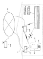
図4を用いて、携帯型プリンタ100及び操作端末200の機能的構成を説明する。
<Functional configuration of printer and operation terminal>
A functional configuration of the
図4において、携帯型プリンタ100は、被印刷用紙Sに所望の印刷を行う上記サーマルラインヘッド112と、上記プラテンローラ111と、制御回路143と、例えばRAMやROM等からなるメモリ144と、上記アクセスポイントAPとの間でプリンタ側アンテナ141(通信アンテナ)を介して行われる上記相互認識無線通信の制御を行う通信制御部142と、タグアンテナ151による近距離通信である所定のタグ通信により情報を送受信可能とするプリンタ用無線タグTとを有している。上記プリンタ側アンテナ141は、タグアンテナ151により行われる、上記タグ通信とは異なる上記相互認識無線通信により、アクセスポイントAPとの情報送受信を行う。
4, the
プリンタ用無線タグTは、タグアンテナ151と、タグアンテナ151に接続され、上記受信したアクセスポイント情報Pを記憶可能なIC回路部150とを有している。
The printer wireless tag T includes a
タグアンテナ151は、操作端末200が予め取得したアクセスポイント情報P(アクセスポイントACPの識別情報であるアクセスポイントID、及び、パスワード等。後述の図7参照)を、当該操作端末200から受信可能である(詳細は後述)。なお、アクセスポイントACPの識別情報としてはアクセスポイントIDに限られず、その他の情報、例えばアクセスポイントの固有の名称や記号等であってもよい。
The
IC回路部150は、当該IC回路部150の回路素子の作動を制御する制御部157と、例えばデュアルポートタイプのメモリとして構成されたメモリ部155とを備えている。メモリ部155の一方のポート155aは制御部157と接続されている。また、メモリ部155の他方のポート155bは外部出力端子であり、有線接続部154を介して上記制御回路143と接続されている。
The
操作端末200は、CPU203と、例えばRAMやROM等からなるメモリ204と、上記操作部202と、上記表示部201と、ソリッドステートドライブ装置(SSD)等から成り各種情報を記憶する大容量記憶装置205と、第1アンテナ208Aを備えたRFID用無線送受信部208と、第2アンテナ206Aを備えた相互認識無線通信制御部206とを備えている。
The
RFID用無線送受信部208は、CPU203の制御に従い、上記プリンタ用無線タグTのタグアンテナ151と第1アンテナ208Aとの間の無線通信(上記タグ通信)により、携帯型プリンタ100に上記アクセスポイント情報Pを送信し、プリンタ用無線タグTへ当該アクセスポイント情報Pを書き込む(図7(b)参照)。この例では、例えば13.56MHz帯を使った近距離無線通信方式が利用され、通信距離が10cm未満のエリアに限定されている。
The RFID wireless transmission /
相互認識無線通信制御部206は、CPU203の制御に従い、第2アンテナ206Aと上記アクセスポイントACPを介しての相互認識無線通信により、例えば操作端末200から送信された印刷データの受信等、各種情報の送受信のための制御を行う。この通信では、通信距離を10m〜100m程度の範囲として想定している。
The mutual recognition wireless
CPU203は、RAMの一時記憶機能を利用しつつROMに予め記憶されたプログラムに従って信号処理を行い、それによって携帯型プリンタ100との間で各種の指示信号・情報信号の送受を行うようになっている。なお、ROMに記憶されたプログラムには、印刷処理を実行するためのプログラムが含まれている。
The
大容量記憶装置205(メモリ204でもよい)には、文字スタイルやフォント等の所定の書式の種類ごとに、印刷指令をプリンタコード(詳細は省略)に変換するためのプログラムが記憶されている。 The mass storage device 205 (or the memory 204) stores a program for converting a print command into a printer code (details omitted) for each type of a predetermined format such as a character style or a font.
<操作端末での処理の流れ>
次に、図5及び図6を用いて、操作端末200内における処理上の機能的構成及び処理の流れについて説明する。
<Processing flow at the operation terminal>
Next, with reference to FIGS. 5 and 6, a functional configuration and process flow in the
図5において、操作端末200の上記メモリ204上に、少なくとも1つのアプリケーションプログラムAPと、プリンタドライバPDのそれぞれのプログラムが展開して起動しており、相互に指示信号と情報信号を送受信可能である。そしてアプリケーションプログラムAPはプリンタドライバPDに対して信号を送受し、またプリンタドライバPDは上記大容量記憶装置205と信号を送受信すると共に、上記通信制御部206、上記アクセスポイントACP、及び上記通信制御部142を介し、携帯型プリンタ100と情報送受信可能である。
In FIG. 5, at least one application program AP and a printer driver PD program are deployed and started on the
これらアプリケーションプログラムAPとプリンタドライバPDは、いずれも操作端末200が備える1つの上記CPU203によって実行される。すなわち、例えば公知のタイムシェアリングシステム(TSS)などの時分割での割り込み制御によって、CPU203においてそれぞれ個別に独立して実行される。またプリンタドライバPDについては、操作端末200の基本OSに予め組み込まれたものでもよいし、他のアプリケーションと同様にOS上で個別に起動されるプログラムであってもよい。
Both the application program AP and the printer driver PD are executed by one
ここで、アプリケーションプログラムAPとしては、文書作成や画像作成用のアプリケーションプログラム、例えば文書作成・管理用の文書管理用アプリケーションプログラムや、写真やイラスト等の画像作成・管理用の画像管理用アプリケーションプログラムなどがある。そして、アプリケーションプログラムAPは、操作者による操作部202の操作に対応して印刷指令を含む印刷ジョブを生成し、その生成された印刷ジョブは、アプリケーションプログラムAPからプリンタドライバPDへと出力される。
Here, as the application program AP, an application program for document creation and image creation, for example, a document management application program for document creation / management, an image management application program for image creation / management such as photographs and illustrations, etc. There is. Then, the application program AP generates a print job including a print command in response to the operation of the
そして、図6に示すように、プリンタドライバPDは、アプリケーションプログラムAPから出力された上記印刷ジョブを受け付け、印刷ジョブに含まれる印刷指令を対応するプリンタコードに変換する。そして、上記アクセスポイントACPを介し、携帯型プリンタ100に対してこの変換したプリンタコード(印刷データ)を出力することができる。携帯型プリンタ100は、プリンタドライバPDから入力されたプリンタコードに基づいて、必要な各種処理を行い、その後必要な印刷を行う。なお、上述した、図6のフローに示す印刷処理を実行するための印刷処理プログラムは、上記アプリケーションプログラムAPとプリンタドライバPDとの両方を含むプログラムである。
As shown in FIG. 6, the printer driver PD accepts the print job output from the application program AP, and converts the print command included in the print job into a corresponding printer code. The converted printer code (print data) can be output to the
<本実施形態の特徴>
上記基本構成において、本実施形態の携帯型プリンタ100の特徴は、アクセスポイントAPCに係わる上記アクセスポイント情報Pをタグ通信で取得することで、アクセスポイントAPCとの接続を(ユーザの手動操作なしに)自動的に設定することにある。以下、その内容を順を追って説明する。
<Features of this embodiment>
In the above basic configuration, the
本実施形態の携帯型プリンタ100では、上述したように、印刷データ(上記プリンタコード)は、プリンタ側アンテナ141を介したアクセスポイントAPCとの上記相互認識無線通信により取得される。このように、相互認識無線通信によって印刷データを取得する場合、当該携帯型プリンタ100の使用場所をカバーしている上記アクセスポイントACPに対して、当該携帯型プリンタ100を情報送受信可能に接続する必要がある。例えば、ユーザが上記携帯型プリンタ100を新規に購入した場合、例えばパソコン等を上記携帯型プリンタ100に例えば有線にて接続し、当該パソコン等からの操作によって携帯型プリンタ100とアクセスポイントACPとの上記相互認識無線通信による接続を設定する必要があり、面倒である。
In the
<本実施形態の手法>
そこで、本実施形態では、予め操作端末200が取得したアクセスポイント情報Pが上記タグ通信によってプリンタ用無線タグTに引き渡される。これにより、そのアクセスポイント情報Pを用いて、携帯型プリンタ100はアクセスポイントACPに対し情報送受信可能に確実に接続される。
<Method of this embodiment>
Therefore, in this embodiment, the access point information P acquired by the
すなわち、図7(a)に示すように、まず、操作端末200の相互認識無線通信制御部206及び第2アンテナ206Aを介し、適宜のアクセスポイントACPに対し相互認識無線通信が行われる。そして、当該アクセスポイントACPに関するアクセスポイントID”xxmobile WiFixxxx”が、予め操作端末200によって取得される。なお、この時点で、本実施形態では、当該アクセスポイントACPのパスワードは、ユーザが既に知見しており、適宜のタイミングで(例えば操作部202での手動入力により)操作端末200へと入力されている。操作端末200は、上記取得されたアクセスポイントID及びパスワード(これら2つが上記アクセスポイント情報Pを構成する)を例えばメモリ204に記憶しておく。
That is, as shown in FIG. 7A, first, mutual recognition wireless communication is performed with respect to an appropriate access point ACP via the mutual recognition wireless
この状態で、図7(b)に示すように、例えば操作端末200を携帯型プリンタ100に近接させることで、上記操作端末200により取得された上記アクセスポイント情報P(図示の例ではアクセスポイントID”xxmobile WiFixxxx”及びパスワード)が上記タグ通信を介して上記携帯型プリンタ100のプリンタ用無線タグTに対し書き込まれる。図示の例では、このとき操作端末200の表示部201には、アクセスポイント情報Pが上記プリンタ用無線タグTに書き込まれたことを表す「Sent SSID & PW to RFID−tag」と、通信日時「2011−10−30 00:06:17」と、アクセスポイント情報P”xxmobile WiFixxxx”等が表示されている。上記プリンタ用無線タグTに書き込まれたアクセスポイント情報Pは、上記有線通信を介し、携帯型プリンタ100のメモリ144に取得される。
In this state, as shown in FIG. 7B, for example, by bringing the
そして、図7(c)に示すように、この取得されたアクセスポイント情報Pを用いて、対応するアクセスポイントACPに対し、通信制御部142のプリンタ側アンテナ141が相互認識無線通信による情報送受信を試行する。この情報送受信が成功したら、携帯型プリンタ100内の制御回路143は、アクセスポイントACPとの相互認識無線通信によって、例えば前述のように相互認識無線通信制御部206及び第2アンテナ206Aを用いて操作端末200のから送信された上記印刷データを取得する。そして、携帯型プリンタ100は、当該取得された印刷データを用いて、被印刷用紙Sへの印刷を実行することができる。
Then, as shown in FIG. 7C, using the acquired access point information P, the printer-
<操作端末の制御手順>
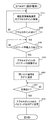
上記の内容を実現するために、操作端末200の上記CPU203によって実行される、上記印刷処理プログラムに基づく制御内容を、図8を用いて説明する。
<Operation terminal control procedure>
Control contents based on the print processing program executed by the
まずステップS10で、CPU203は、相互認識無線通信制御部206及び第2アンテナ206Aを介し、相互認識無線通信のアクセスポイントACPを公知の適宜の手法により検索する。
First, in step S10, the
その後、ステップS20では、CPU203は、ステップS10での検索により検出できたアクセスポイントACPがあるか否かを判定する。検出できたアクセスポイントACPがない場合には、ステップS20の判定が満たされず(S20:NO)、ステップS10に戻り、アクセスポイントACPが検索されるまで同様の手順が繰り返される。検出できたアクセスポイントACPがあった場合(この場合には当該アクセスポイントACPのアクセスポイントIDが取得されている)には、ステップS20の判定が満たされ(S20:YES)、ステップS30に移行する。
Thereafter, in step S20, the
ステップS30では、CPU203は、操作者により、操作部202を介し、当該操作端末200のパスワードが手動で入力されたか否かを判定する。パスワードが手動で入力されるまではステップS30の判定が満たされず(S30:NO)、ループ待機する。パスワードが手動で入力されると、ステップS30の判定が満たされ(S30:YES)、ステップS40に移行する。
In step S30, the
ステップS40では、CPU203は、ステップS20で検索されたアクセスポイントACPに関するアクセスポイント情報P(上記の例ではステップS10での検索により取得されたアクセスポイントID”xxmobile WiFixxxx”、及び、ステップS30で入力されたパスワード)を操作端末200のメモリ204(又は大容量記憶装置205でもよい)に記憶する。
In step S40, the
その後、ステップS50で、CPU203は、プリンタ用無線タグTの応答を求める問いかけ信号を生成し、RFID用無線送受信部208及び第1アンテナ208Aを介し、携帯型プリンタ100のプリンタ用無線タグTに送信する。
Thereafter, in step S50, the
そして、ステップS60で、CPU203は、上記問いかけ信号に対する上記プリンタ用無線タグTからの応答信号が、第1アンテナ208A及びRFID用無線送受信部208を介し受信されたか否かを判定する。応答信号が受信されるまではステップS60の判定が満たされず(S60:NO)、ループ待機する。応答信号が受信されると、ステップS60の判定が満たされ(S60:YES)、ステップS70に移行する。
In step S60, the
ステップS70では、CPU203は、上記ステップS40で記憶したアクセスポイントACPのアクセスポイントID(上記の例では”xxmobile WiFixxxx”)及びパスワードを、第1アンテナ208A及びRFID用無線送受信部208を介し、プリンタ用無線タグTに送信する。このステップS70が完了したら、このフローを終了する。
In step S70, the
<プリンタの制御手順>
一方、携帯型プリンタ100の制御回路143によって実行される印刷処理内容を、図9を用いて説明する。
<Printer control procedure>
On the other hand, the contents of print processing executed by the
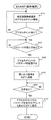
図9において、まず、ステップS240で、制御回路143は、上記図8のステップS70で操作端末200から送信されたアクセスポイント情報(アクセスポイントID及びパスワード)が、タグアンテナ151を介したタグ通信により、プリンタ用無線タグT(詳細には上記メモリ部155)に書き込まれたか否かを判定する。上記アクセスポイント情報Pが取得されるまではステップS240の判定が満たされず(S240:NO)、ループ待機する。アクセスポイント情報Pが取得されると、ステップS240の判定が満たされ(S240:YES)、ステップS245に移行する。
In FIG. 9, first, in step S240, the
ステップS245では、制御回路143は、ステップS240でプリンタ用無線タグTにおいて取得されたアクセスポイント情報Pを、上記有線通信を介して取得し、例えばメモリ144に記憶する。このステップS245が各請求項記載の情報取得手段として機能する。
In step S245, the
その後、ステップS250で、制御回路143は、上記ステップS240で取得されたアクセスポイント情報Pに対応する(=アクセスポイントIDにより特定される)アクセスポイントACPに対し、通信制御部142及びプリンタ側アンテナ141を用いた相互認識無線通信により情報送受信を試行する。このステップS250が各請求項記載の送受信試行手段として機能する。
Thereafter, in step S250, the
そして、ステップS255に移り、制御回路143は、ステップS250での情報送受信の試行通信が成功したか否かを判定する。試行通信が成功していない場合は判定が満たされず(S255:NO)、ステップS250に戻り、同様の手順が繰り返される。上記試行通信が成功した場合は判定が満たされ(S255:YES)、ステップS260に移行する。
Then, the process proceeds to step S255, and the
ステップS260では、制御回路143は、通信制御部142及びプリンタ側アンテナ141を用いた相互認識無線通信により、印刷データをアクセスポイントACPから取得する。このステップS260が各請求項記載のデータ取得手段として機能する。
なお、このステップS260における印刷データの取得は、上記したPDA(携帯情報端末)やスマートフォン(PDA機能を備えた携帯電話)等の操作端末200からではなく、無線通信回線NW(WiFiネットワーク)に接続されている汎用コンピュータPC(図1参照)等の別の端末から上記相互認識無線通信によって取得しても良い。この場合、操作端末200は、携帯型プリンタ100が上記別の端末から印刷データを取得するための、アクセスポイントACPとの接続設定を構築する役割となる。
In step S260, the
The print data acquisition in step S260 is not performed from the
その後、ステップS265で、制御回路143は、上記ステップS260で取得した印刷データを、例えばRAMやROM等からなる上記メモリ144に記憶する。
Thereafter, in step S265, the
そして、ステップS270で、制御回路143は、プラテンローラ111及びサーマルラインヘッド112を連携して制御し、上記ステップS265でメモリ144に記憶された印刷データを用いて被印刷用紙Sに対し所望の印刷を行う。このステップS270が各請求項記載の印刷制御手段として機能する。
In step S270, the
そして、ステップS275で、制御回路143は、上記ステップS270で印刷が完了した内容に対応する上記印刷データを、上記メモリ144から消去する。その後、ステップS240に戻り、同様の手順を繰り返す。
In step S275, the
以上説明したように、本実施形態では、予め操作端末200が取得したアクセスポイント情報Pをプリンタ用無線タグTに引き渡すことで、そのアクセスポイント情報Pを用いて、携帯型プリンタ100がアクセスポイントACPに対し情報送受信可能に接続される。これにより、例えばユーザが新規の携帯型プリンタ100を購入して建物(自宅)Hに設置した際、建物H内のアクセスポイントACPを介して、操作端末200等から携帯型プリンタ100へ所望の印刷データを簡単に送ることができる。したがって、ユーザは、迅速かつ簡単に所望の印刷を実行することができる。
As described above, in the present embodiment, the access point information P acquired in advance by the
なお、本発明は、上記実施形態に限られるものではなく、その趣旨及び技術的思想を逸脱しない範囲内で種々の変形が可能である。以下、そのような変形例を順を追って説明する。なお、上記実施形態と同等の部分には同一の符号を付し、適宜説明を省略又は簡略化する。 The present invention is not limited to the above-described embodiment, and various modifications can be made without departing from the spirit and technical idea of the present invention. Hereinafter, such modifications will be described in order. In addition, the same code | symbol is attached | subjected to the part equivalent to the said embodiment, and description is abbreviate | omitted or simplified suitably.
(1)プリンタが操作端末へ送受信成功報告を送信する場合
本変形例では、図10(a)に示すように、上記図7(a)と同様、まず、操作端末200による適宜のアクセスポイントACPへの相互認識無線通信によってアクセスポイントID”xxmobile WiFixxxx”が取得される。
(1) When the printer transmits a transmission / reception success report to the operation terminal In this modified example, as shown in FIG. 10A, first, as in FIG. The access point ID “xxmobile WiFixxxx” is acquired by mutual recognition wireless communication.
その後、上記図7(b)に対応する図10(b)に示すように、操作端末200をプリンタ用無線タグTに近接させることで、前述と同様、上記操作端末200により取得された上記アクセスポイント情報P(図示の例ではアクセスポイントID”xxmobile WiFixxxx”)及び操作者が事前に手動入力済みのパスワードがプリンタ用無線タグTに対し書き込まれる。その際、本変形例では、上記アクセスポイント情報Pに加え、操作端末200自体のアドレス情報Q(この例ではIPアドレス”001987 xxxx”)も、上記プリンタ用無線タグTに対し併せて書き込まれる。
Thereafter, as shown in FIG. 10 (b) corresponding to FIG. 7 (b), by bringing the
このとき、図示の例では、操作端末200の表示部201には、前述と同様のアクセスポイント情報Pが取得されたことを表す上記「Sent SSID & PW to RFID−tag」、通信日時「2011−10−30 00:06:17」、及びアクセスポイント情報P”xxmobile WiFixxxx”に加え、上記アドレス情報QとしてのIPアドレス”001987 xxxx”等が表示されている。このようにして書き込まれたアクセスポイント情報P及びアドレス情報Qは、前述同様、上記有線通信を介し、携帯型プリンタ100のメモリ144に取得される。
At this time, in the illustrated example, the
その後、図10(c)に示すように、前述の図7(c)と同様、上記取得されたアクセスポイント情報Pを用いて、対応するアクセスポイントACPに対し相互認識無線通信による情報送受信が試行される。そして、本変形例では、この情報送受信が成功したら、上記アドレス情報Qを用いて操作端末200を特定しつつ、上記プリンタ側アンテナ141を介した相互認識無線通信により、当該操作端末200に対し、送受信が成功した旨の報告を送信する。すなわち、前述のようにしてアクセスポイント情報Pやアドレス情報Qを携帯型プリンタ100に引き渡した操作端末200は、携帯型プリンタ100から通信が成功した旨の返信をもらうこととなる。
Thereafter, as shown in FIG. 10 (c), similar to FIG. 7 (c), using the acquired access point information P, information transmission / reception by mutual recognition wireless communication is attempted with respect to the corresponding access point ACP. Is done. In this modification, when this information transmission / reception is successful, the
<操作端末の制御手順>
本変形例における操作端末200のCPU203が実行する制御手順を図11に示す。図11に示すフローでは、上記実施形態における図8のステップS70に代えて、ステップS70′が設けられている点が異なる。図8と同様のステップS10〜ステップS60の後、新たに設けたステップS70′に移る。ステップS70′では、CPU203は、上記ステップS40で記憶されたアクセスポイントACPに関するアクセスポイント情報P及びパスワードに加え、当該操作端末200のアドレス情報Q(例えばIPアドレス)を、RFID用無線送受信部208及び第1アンテナ208Aを介しプリンタ用無線タグTに送信して書き込む。その後、このフローを終了する。
<Operation terminal control procedure>
FIG. 11 shows a control procedure executed by the
<プリンタの制御手順>
本変形例における携帯型プリンタ100の制御回路143によって実行される印刷処理手順を図12に示す。図12に示すフローでは、上記実施形態の図9のフローにおけるステップS245に代えてステップS245′が設けられ、さらにステップS260とステップS265の間に新たにステップS261が設けられる。
<Printer control procedure>
FIG. 12 shows a printing processing procedure executed by the
すなわち、上記図9と同様のステップS240の後、新たに設けたステップS245′に移る。ステップS245′では、制御回路143は、ステップS240でプリンタ用無線タグTにおいて取得されたアクセスポイント情報P(アクセスポイントID及びパスワードを含む)を、上記有線通信を介して取得する。また本変形例では、上記に加え、ステップS240でプリンタ用無線タグTにおいて取得された操作端末200のアドレス情報(図11のステップS70′参照)も、併せて上記有線通信を介して取得する。これら取得された各情報は、上記同様、例えばメモリ144に記憶される。このステップS245′が、本変形例における各請求項記載の情報取得手段として機能する。
That is, after step S240 similar to FIG. 9, the process proceeds to newly provided step S245 ′. In step S245 ′, the
その後のステップS250、ステップS255、ステップS260は上記図9と同様である。ステップS260の完了後、新たに設けたステップS261に移る。 Subsequent steps S250, S255, and S260 are the same as those in FIG. After completion of step S260, the process proceeds to newly provided step S261.
ステップS261では、制御回路143は、(ステップS245′で取得した操作端末200のアドレス情報を用いて、通信完了報告(送受信成功報告)を上記相互認識無線通信により、アクセスポイントACPを介して上記操作端末200のアドレス)に送信する。上記通信完了報告は、上記ステップS255でアクセスポイントACPとの通信が成功し情報送受信ができたことを報告するものである。
In step S261, the
また、本変形例では、当該情報送受信に成功したアクセスポイントのアクセスポイントID(上記図12のステップS245′においてプリンタ用無線タグTから取得されるが、その後のステップS250での相互認識無線通信成功時にも取得される)、についても、例えば上記通信完了報告に付される形で、ステップS261において操作端末200へ送信される。これにより、当該通信完了報告及びアクセスポイントIDが、操作端末200によって取得される。なお、このステップS261が各請求項記載の報告送信手段として機能する。その後のステップS265、ステップS270、ステップS275は図9と同様であり、説明を省略する。
Further, in the present modification, the access point ID of the access point that has succeeded in transmitting and receiving the information (obtained from the wireless tag T for the printer in step S245 ′ in FIG. 12, but succeeded in mutual recognition wireless communication in the subsequent step S250) Is also transmitted to the
本変形例においては、上記通信完了報告により、プリンタ100がアクセスポイントACPとの情報送受信に成功したこと、及び、どのアクセスポイントACPとの接続に成功したか、が操作端末200によって取得される。したがって、例えば、操作端末200が、上記通信完了報告に対応した報知を実行することにより、ユーザは、携帯型プリンタ100が確かにアクセスポイントACPと接続されたこと、及び、どのアクセスポイントACPに接続されたか、を、視覚又は聴覚等により認識することができる。
In the present modification, the
(3)複数のアクセスポイントが存在する場合
例えば、図13に示すように、建物H(例えば上記同様のユーザの自宅、あるいはオフィスビル等)内にアクセスポイントACPが複数混在している場合、操作端末200及び携帯型プリンタ100は、相互認識無線通信によってそれら複数のアクセスポイントACPと通信可能となる。本変形例では、操作端末200が上記複数のアクセスポイントACPそれぞれに係わる複数のアクセスポイント情報Pを取得し、それぞれを前述のタグ通信によって携帯型プリンタ100へと引き渡す。
(3) When there are a plurality of access points For example, as shown in FIG. 13, when there are a plurality of access points ACP in a building H (for example, the same user's home or office building as described above) The
上記複数のアクセスポイント情報Pを取得した携帯型プリンタ100は、それら複数のアクセスポイント情報Pを用いて、複数のアクセスポイントACPに対し、順次、情報送受信を試行する。その際、それら複数のアクセスポイントACPのアクセスポイント情報は、例えばリスト形式で取得されており、携帯型プリンタ100は、そのリストアップされたアクセスポイント情報の順番に沿って、各アクセスポイントACPに対し情報送受信を試行する。これにより、例えば、図13に示すように、リストの1番目に記載されたアクセスポイントACPに対し、何らかの事情(例えば電波環境の不具合が生じている場合や、アクセスポイントACPが備えている手持ちのIPアドレスが全て使用中の場合)で情報送受信ができなかった場合には、その次の2番目に記載されたアクセスポイントACPに対し、情報送受信が行われる(以下順次、同様である)。
The
<プリンタの制御手順>
上記手法を実現するために、本変形例における携帯型プリンタ100の制御回路143によって実行される、印刷処理内容を、図14のフローを用いて説明する。
<Printer control procedure>
The contents of the printing process executed by the
図14のフローでは、図9のフローにおけるステップS245に代えて
図12と同様のステップS245′が設けられ、このステップS245′とステップS260との間に、ステップS246、ステップS247、ステップS248、ステップS251、ステップS252、ステップS253、及び、ステップS254が新たに設けられる。また、図9のフローのステップS260とステップS265との間に、新たにステップS262が設けられる。
In the flow of FIG. 14, instead of step S245 in the flow of FIG. 9, step S245 ′ similar to FIG. 12 is provided, and between step S245 ′ and step S260, step S246, step S247, step S248, step S251, step S252, step S253, and step S254 are newly provided. Further, step S262 is newly provided between step S260 and step S265 in the flow of FIG.
図14において、上記図9と同様のステップS240の後、図12と同様のステップS245′に移る。ステップS245′では、上記図12と同様、制御回路143は、ステップS240でプリンタ用無線タグTにおいて取得されたアクセスポイント情報P及び操作端末200のアドレス情報を、上記有線通信を介して取得し、例えばメモリ144に記憶する。但しこの変形例では、図13を用いて上述したように、上記ステップS240では複数のアクセスポイント情報Pが取得される場合もある(1つの場合もある)。本変形例においても、このステップS245′が各請求項記載の情報取得手段として機能する。その後、新たに設けたステップS246に移る。
14, after step S240 similar to FIG. 9, the process proceeds to step S245 ′ similar to FIG. In step S245 ′, as in FIG. 12, the
ステップS246では、制御回路143は、上記ステップS245′で取得されたアクセスポイント情報Pが複数あったか否か(言い換えればアクセス可能なアクセスポイントACPが複数存在するか否か)を判定する。アクセスポイント情報Pが複数存在すれば、ステップS246の判定が満たされ(S246:YES)、ステップS251に移行する。
In step S246, the
ステップS251では、制御回路143は、上記のようにしてアクセス可能とされた複数のアクセスポイントACPうち、1つのアクセスポイントACPに対し、図9の上記ステップS250と同様、通信制御部142及びプリンタ側アンテナ141を用いた相互認識無線通信により、情報送受信を試行する。その後、ステップS252に移行する。
In step S251, the
ステップS252では、制御回路143は、上記図9のステップS252と同様、ステップS251での情報送受信の試行通信が成功したか否かを判定する。試行通信が成功していない場合には、ステップS252の判定が満たされず(S252:NO)、ステップS253に移行する。試行通信が成功した場合にはステップS252の判定が満たされ(S252:YES)、ステップS260に移行する。
In step S252, the
ステップS253では、制御回路143は、上記ステップS251及びステップS252での繰り返しにより順次行われる上記試行通信が、上記ステップS245′でアクセスポイント情報Pを取得できた全てのアクセスポイントACPに対して行われたか否かを判定する。全てのアクセスポイントACPに対しては試行通信が終了していない場合は判定が満たされず(S253:NO)、ステップS251に戻り、同様の手順を繰り返す。これにより、1つのアクセスポイントACPに対し情報送受信ができなかった場合、別のアクセスポイントACPに対し情報送受信が試行され、これを全てのアクセスポイントACPに対して行う。このような繰り返しによって全てのアクセスポイントACPに対して試行通信が終了した場合は判定が満たされ(S253:YES)、ステップS254に移行する。
In step S253, the
ステップS254では、制御回路143は、上記ステップS252→ステップS253→ステップS251→・・での繰り返しによってもいずれのアクセスポイントACPにも試行通信が成功しなかったことに対応して、エラーメッセージを携帯型プリンタ100の不図示の表示部に表示させる(エラー処理)。 上記ステップS254が完了したら、このフローを終了する。
In step S254, the
一方、上記ステップS246において、上記ステップS245′で取得されたアクセスポイント情報Pが1つしか存在しなかった場合、ステップS246の判定が満たされず(S246:NO)、ステップS247に移行する。 On the other hand, if there is only one access point information P acquired in step S245 ′ in step S246, the determination in step S246 is not satisfied (S246: NO), and the process proceeds to step S247.
ステップS247では、制御回路143は、上記ステップS251と同様、上記1つのアクセスポイントACPに対し、相互認識無線通信による情報送受信を試行する。その後、ステップS248に移行する。なお、このステップS247と上記ステップS251とが、本変形例では、各請求項記載の送受信試行手段として機能する。
In step S247, the
ステップS248では、制御回路143は、上記ステップS252と同様、ステップS247での情報送受信の試行通信が成功したか否かを判定する。試行通信が成功しなかった場合は判定が満たされず(S248:NO)、上記ステップS254に移行して上記のエラー処理を行う。一方、試行通信が成功した場合には判定が満たされ(S248:YES)、上記図9と同様のステップS260に移行し、前述の印刷データの取得処理を実行する。
In step S248, the
ステップS260が完了すると、新たに設けたステップS262に移る。ステップS262では、制御回路143は、上記図12のステップS261と同様、ステップS245′で取得した操作端末200のアドレス情報を用いて、通信完了報告(送受信成功報告)をアクセスポイントACPを介して上記操作端末200のアドレスに送信する。
When step S260 is completed, the process proceeds to newly provided step S262. In step S262, the
その際、本変形例では、各アクセスポイントACPのアクセスポイントIDと、当該アクセスポイントIDに対応した各アクセスポイントACPごとの通信結果(通信が失敗した旨の情報を含む)についても、操作端末200へ送信される。これにより、上記通信完了報告、及び、アクセスポイントIDごとの通信結果が、操作端末200によって取得される。なお、本変形例では、このステップS262が各請求項記載の報告送信手段として機能する。その後のステップS265、ステップS270、ステップS275は図9及び図12と同様であり、説明を省略する。
At this time, in this modification, the
以上示したように、本変形例では、1つのアクセスポイントACPに対し情報送受信ができなかった場合であっても、別のアクセスポイントACPに対し情報送受信を試行することができるので、アクセスポイントACPに対する携帯型プリンタ100の接続成功の可能性を向上することができる。また、複数のアクセスポイントACPのうちどのアクセスポイントACPを用いて携帯型プリンタ100が情報送受信を行っているのか、さらには、どのアクセスポイントACPで情報送受信が失敗した後にどのアクセスポイントACPで情報送受信に成功したのか、等の詳しい情報も、携帯型プリンタ100から操作端末200へ送信可能となる。
As described above, in this modification, even when information cannot be transmitted / received to / from one access point ACP, information transmission / reception can be attempted to another access point ACP. The possibility of a successful connection of the
(4)その他
なお、以上においては、操作端末200や携帯型プリンタ100がアクセスポイントACPに対しWiFi(登録商標)通信で接続される場合を例にとって説明したが、これに限られない。すなわち、操作端末200や携帯型プリンタ100が、無線LANにおけるアドホック通信、ブルートゥース(登録商標)通信等の適宜の相互認識無線通信でアクセスポイントACPに対し接続される場合であっても、上記同様に本発明を適用することができ、同様の効果を得る。
(4) Others In the above, the case where the
また、以上は、バッテリ電源により駆動される携帯用プリンタ100に対し本発明を適用した場合を例にとって説明したが、これに限られない。すなわち、他のプリンタの例として、例えばA4、A3、B4、B5サイズ等の通常の被印刷媒体に画像を形成したり文字を印刷するプリンタや、被印字テープに所望の印刷を行って印字ラベルを作成する印字ラベル作成装置等に対し、本発明を適用してもよい。この場合も同様の効果を得る。
In the above, the case where the present invention is applied to the
なお、以上において、図4に示す矢印は信号の流れの一例を示すものであり、信号の流れ方向を限定するものではない。 In addition, in the above, the arrow shown in FIG. 4 shows an example of the signal flow, and does not limit the signal flow direction.
また、図8、図9、図11、図12、図14に示すフローチャートは本発明を上記フローに示す手順に限定するものではなく、発明の趣旨及び技術的思想を逸脱しない範囲内で手順の追加・削除又は順番の変更等をしてもよい。 In addition, the flowcharts shown in FIGS. 8, 9, 11, 12, and 14 do not limit the present invention to the procedure shown in the above flow, and the procedure is not deviated from the gist and technical idea of the invention. You may add / delete or change the order.
その他、一々例示はしないが、本発明は、その趣旨を逸脱しない範囲内において、種々の変更が加えられて実施されるものである。 In addition, although not illustrated one by one, the present invention is implemented with various modifications within a range not departing from the gist thereof.
1 携帯型プリンタ(プリンタ)
111 プラテンローラ(搬送手段)
112 サーマルラインヘッド(印刷手段)
142 通信制御部
143 制御回路
150 IC回路部
151 タグアンテナ
200 操作端末
203 CPU
206 相互認識無線通信制御部
208 RFID用無線送受信部
ACP アクセスポイント
P アクセスポイント情報
S 被印刷用紙(被印刷媒体)
T プリンタ用無線タグ
1 Portable printer (printer)
111 Platen roller (conveying means)
112 Thermal line head (printing means)
142
206 Mutual recognition wireless
Wireless tag for T printer
Claims (2)
前記搬送手段により搬送される前記被印刷媒体への印刷を実行する印刷手段と、
所定のタグ通信により情報を送受信するタグアンテナ、及び、情報を記憶するIC回路部、を備えたプリンタ用無線タグと、
前記タグアンテナにより行われる前記タグ通信とは異なる、相互認識無線通信により情報を送受信する通信アンテナと、
を有するプリンタであって、
前記タグアンテナを用いた前記タグ通信により前記プリンタ用無線タグが携帯端末から取得した、前記相互認識無線通信の基地局であるアクセスポイントに係わるアクセスポイント情報及び前記携帯端末のアドレス情報を、前記プリンタ用無線タグからの有線通信により取得する情報取得手段と、
前記情報取得手段により取得された前記アクセスポイント情報に対応するアクセスポイントに対し、前記通信アンテナを用いた前記相互認識無線通信により情報送受信を試行する送受信試行手段と、
前記送受信試行手段による情報送受信が成功したとき、前記通信アンテナを用いた前記相互認識無線通信により、所望の印刷データを取得するデータ取得手段と、
前記データ取得手段による所望の印刷データを取得したうえで、前記情報取得手段により取得された前記アドレス情報により前記携帯端末を特定しつつ、前記通信アンテナを介した前記相互認識無線通信により、情報送受信に成功した当該アクセスポイントに係わる識別情報と前記印刷データの取得完了とを含む送受信成功報告を当該携帯端末に送信する報告送信手段と、
前記報告送信手段により前記携帯端末に前記送受信成功報告がされた後に、前記データ取得手段により取得された前記印刷データの印刷を前記被印刷媒体に対し実行するように、前記搬送手段及び前記印刷手段を制御する印刷制御手段と、
を有することを特徴とするプリンタ。 A conveying means for conveying the printing medium;
Printing means for executing printing on the printing medium conveyed by the conveying means;
A wireless tag for a printer including a tag antenna that transmits and receives information by predetermined tag communication, and an IC circuit unit that stores information;
Different from the tag communication performed by the tag antenna, a communication antenna that transmits and receives information by mutual recognition wireless communication,
A printer having:
The printer wireless tag acquired from the portable terminal by the tag communication using the tag antenna, the access point information relating to the access point which is the base station of the mutual recognition wireless communication and the address information of the portable terminal Information acquisition means for acquiring from a wireless tag for wired communication;
Transmission / reception trial means for trying information transmission / reception through the mutual recognition wireless communication using the communication antenna with respect to the access point corresponding to the access point information acquired by the information acquisition means;
A data acquisition unit that acquires desired print data by the mutual recognition wireless communication using the communication antenna when information transmission / reception by the transmission / reception trial unit is successful;
After obtaining desired print data by the data acquisition unit, the mobile terminal is identified by the address information acquired by the information acquisition unit, and information is transmitted / received by the mutual recognition wireless communication via the communication antenna. A report transmission means for transmitting a transmission / reception success report including identification information related to the access point that has been successfully acquired and completion of acquisition of the print data to the mobile terminal;
The transport unit and the printing unit are configured to execute printing of the print data acquired by the data acquisition unit on the printing medium after the report transmission unit reports the successful transmission / reception to the portable terminal. Printing control means for controlling
A printer comprising:
前記情報取得手段は、
前記プリンタ用無線タグが前記携帯端末から取得した、複数の前記アクセスポイントそれぞれに係わる複数の前記アクセスポイント情報を取得し、
前記送受信試行手段は、
前記情報取得手段により取得された前記複数のアクセスポイント情報をそれぞれ用いて、前記複数のアクセスポイントに対し、順次、情報送受信を試行可能に構成され、
前記報告送信手段は、
前記送受信試行手段による情報送受信が成功したとき、前記識別情報を含む前記送受信成功報告及び前記識別情報に対応した前記各アクセスポイントごとの通信結果を前記携帯端末に対して送信する
ことを特徴とするプリンタ。
The printer according to claim 1 .
The information acquisition means includes
A plurality of access point information related to each of the plurality of access points acquired by the wireless tag for printer from the mobile terminal;
The transmission / reception trial means includes
Using each of the plurality of access point information acquired by the information acquisition means, each of the plurality of access points is configured to be able to try information transmission and reception sequentially ,
The report transmitting means includes
When information transmission / reception by the transmission / reception trial unit is successful, the communication success report including the identification information and a communication result for each access point corresponding to the identification information are transmitted to the portable terminal. Printer characterized by.
Priority Applications (3)
| Application Number | Priority Date | Filing Date | Title |
|---|---|---|---|
| JP2012069806A JP5962896B2 (en) | 2012-03-26 | 2012-03-26 | Printer |
| US13/846,964 US10049313B2 (en) | 2012-03-26 | 2013-03-19 | Printer |
| US16/102,101 US10540581B2 (en) | 2012-03-26 | 2018-08-13 | Printer |
Applications Claiming Priority (1)
| Application Number | Priority Date | Filing Date | Title |
|---|---|---|---|
| JP2012069806A JP5962896B2 (en) | 2012-03-26 | 2012-03-26 | Printer |
Publications (2)
| Publication Number | Publication Date |
|---|---|
| JP2013201687A JP2013201687A (en) | 2013-10-03 |
| JP5962896B2 true JP5962896B2 (en) | 2016-08-03 |
Family
ID=49211535
Family Applications (1)
| Application Number | Title | Priority Date | Filing Date |
|---|---|---|---|
| JP2012069806A Active JP5962896B2 (en) | 2012-03-26 | 2012-03-26 | Printer |
Country Status (2)
| Country | Link |
|---|---|
| US (2) | US10049313B2 (en) |
| JP (1) | JP5962896B2 (en) |
Families Citing this family (27)
| Publication number | Priority date | Publication date | Assignee | Title |
|---|---|---|---|---|
| JP5962896B2 (en) | 2012-03-26 | 2016-08-03 | ブラザー工業株式会社 | Printer |
| US9202037B2 (en) * | 2012-06-08 | 2015-12-01 | General Electric Company | System and method for using machine readable code to commission device applications |
| JP5962564B2 (en) | 2013-03-28 | 2016-08-03 | ブラザー工業株式会社 | Communication control program and communication device |
| JP5838988B2 (en) | 2013-03-28 | 2016-01-06 | ブラザー工業株式会社 | Communication program and communication device |
| JP6558134B2 (en) | 2015-08-05 | 2019-08-14 | ブラザー工業株式会社 | COMMUNICATION DEVICE AND COMPUTER PROGRAM FOR COMMUNICATION DEVICE |
| JP6503968B2 (en) | 2015-08-05 | 2019-04-24 | ブラザー工業株式会社 | Communication device and computer program for communication device |
| JP6724338B2 (en) * | 2015-10-30 | 2020-07-15 | ブラザー工業株式会社 | Communication equipment |
| CN107346315B (en) * | 2016-05-06 | 2020-10-27 | 曲立东 | Object data association index system and construction and application method thereof |
| US10885420B2 (en) | 2016-12-14 | 2021-01-05 | Ajay Khoche | Package sealing tape types with varied transducer sampling densities |
| US11295190B2 (en) | 2016-12-14 | 2022-04-05 | Hendrik J Volkerink | Correlated asset identifier association |
| US11138490B2 (en) | 2016-12-14 | 2021-10-05 | Ajay Khoche | Hierarchical combination of distributed statistics in a monitoring network |
| US10445634B2 (en) | 2016-12-14 | 2019-10-15 | Trackonomy Systems, Inc. | Fabricating multifunction adhesive product for ubiquitous realtime tracking |
| US10902310B2 (en) | 2016-12-14 | 2021-01-26 | Trackonomy Systems, Inc. | Wireless communications and transducer based event detection platform |
| US10819137B2 (en) | 2016-12-14 | 2020-10-27 | Ajay Khoche | Energy harvesting wireless sensing system |
| JP2019142111A (en) * | 2018-02-21 | 2019-08-29 | ブラザー工業株式会社 | Printer and printing processing program |
| JP7159761B2 (en) | 2018-09-28 | 2022-10-25 | ブラザー工業株式会社 | Application programs and mobile terminals |
| CN109150634B (en) * | 2018-10-25 | 2022-02-25 | 新华三技术有限公司 | Access point configuration method and device |
| US11308370B2 (en) | 2019-04-04 | 2022-04-19 | Trackonomy Systems, Inc. | Correlating asset identifiers |
| WO2020247354A1 (en) | 2019-06-05 | 2020-12-10 | Trackonomy Systems, Inc. | Temperature monitoring in cold supply chains |
| MX2022003135A (en) | 2019-09-13 | 2022-08-04 | Trackonomy Systems Inc | Roll-to-roll additive manufacturing method and device. |
| JP7342580B2 (en) * | 2019-09-30 | 2023-09-12 | ブラザー工業株式会社 | Programs and information processing equipment |
| US11587425B1 (en) | 2020-05-17 | 2023-02-21 | Trackonomy Systems, Inc. | Next generation building access control, indoor locationing, and interaction tracking |
| US11864058B1 (en) | 2020-10-04 | 2024-01-02 | Trackonomy Systems, Inc. | Flexible tracking device for cables and equipment |
| WO2022020822A1 (en) | 2020-07-24 | 2022-01-27 | Trackonomy Systems, Inc. | Tearing to turn on wireless node with multiple cutouts for re-use |
| US11527148B1 (en) | 2020-10-04 | 2022-12-13 | Trackonomy Systems, Inc. | Augmented reality for guiding users to assets in IOT applications |
| US11819305B1 (en) | 2020-10-05 | 2023-11-21 | Trackonomy Systems, Inc. | Method for determining direction of movement through gates and system thereof |
| WO2022126020A1 (en) | 2020-12-12 | 2022-06-16 | Trackonomy Systems, Inc. | Flexible solar-powered wireless communication device |
Family Cites Families (28)
| Publication number | Priority date | Publication date | Assignee | Title |
|---|---|---|---|---|
| US7522049B2 (en) * | 2002-10-18 | 2009-04-21 | Aeroscout, Ltd. | Wireless local area network (WLAN) method and system for presence detection and location finding |
| US7694883B2 (en) * | 2003-05-01 | 2010-04-13 | Brother Kogyo Kabushiki Kaisha | RFID label, method for producing the RFID label, device for producing the RFID label, sheet member (tag sheet) used for the RFID label, and cartridge attached to the device for producing the RFID label |
| JP4438063B2 (en) | 2004-11-05 | 2010-03-24 | キヤノン株式会社 | COMMUNICATION SYSTEM, COMMUNICATION DEVICE, COMMUNICATION METHOD, AND PROGRAM |
| JP2006163791A (en) * | 2004-12-07 | 2006-06-22 | Fuji Xerox Co Ltd | Document processing system |
| JP4735022B2 (en) * | 2005-04-27 | 2011-07-27 | 日本電気株式会社 | Wireless LAN terminal, wireless LAN terminal scanning operation method, and scanning operation program |
| JP4656637B2 (en) | 2005-04-27 | 2011-03-23 | キヤノン株式会社 | COMMUNICATION DEVICE, COMMUNICATION SYSTEM AND COMMUNICATION PARAMETER SETTING METHOD |
| JP4774823B2 (en) | 2005-06-16 | 2011-09-14 | ソニー株式会社 | Wireless communication system, wireless communication setting method, wireless communication apparatus, wireless communication setting program, and wireless communication setting program storage medium |
| WO2007015296A1 (en) * | 2005-08-03 | 2007-02-08 | National Institute Of Information And Communications Technology Incorporated Administrative Agency | Radio communication system |
| JP2007088726A (en) | 2005-09-21 | 2007-04-05 | Fuji Xerox Co Ltd | Device, and wireless lan setting system and method therefor |
| JP4506658B2 (en) * | 2005-11-30 | 2010-07-21 | ソニー株式会社 | Wireless communication system, communication apparatus, setting information providing method, setting information obtaining method, and computer program |
| JP4801441B2 (en) * | 2005-12-28 | 2011-10-26 | 株式会社キングジム | Label printing system, label printing method, and label printing program |
| JP4973223B2 (en) * | 2007-02-15 | 2012-07-11 | 富士通株式会社 | Network reconfiguration method, router, and network reconfiguration system |
| JP2007151194A (en) | 2007-03-12 | 2007-06-14 | Brother Ind Ltd | Wireless lan system, communication terminal, and communication program |
| JP4411555B2 (en) * | 2007-03-26 | 2010-02-10 | ブラザー工業株式会社 | Tag label making device |
| JP4877032B2 (en) | 2007-04-19 | 2012-02-15 | ソニー株式会社 | Wireless communication apparatus, wireless communication method and program |
| JP5053715B2 (en) | 2007-05-31 | 2012-10-17 | キヤノン株式会社 | COMMUNICATION DEVICE, COMMUNICATION DEVICE CONTROL METHOD, AND COMPUTER PROGRAM FOR CAUSING COMPUTER TO EXECUTE THE CONTROL METHOD |
| US8068607B2 (en) | 2007-07-31 | 2011-11-29 | Ricoh Company, Limited | Information processing apparatus and information processing method |
| JP4984327B2 (en) * | 2007-08-10 | 2012-07-25 | ブラザー工業株式会社 | Wireless tag for printer and printer |
| US8341083B1 (en) * | 2007-09-12 | 2012-12-25 | Devicefidelity, Inc. | Wirelessly executing financial transactions |
| TWI412245B (en) * | 2007-12-28 | 2013-10-11 | Htc Corp | Method for building a network connection and network device thereof |
| JP2009237670A (en) * | 2008-03-26 | 2009-10-15 | Brother Ind Ltd | Tag label creation apparatus |
| JP4720845B2 (en) * | 2008-04-09 | 2011-07-13 | ブラザー工業株式会社 | Article management system, portable wireless tag communication device |
| KR20110029435A (en) | 2009-09-15 | 2011-03-23 | 삼성전자주식회사 | Priter and method for printing document of mobile terminal and the mobile terminal thereof |
| US8813198B2 (en) | 2011-07-05 | 2014-08-19 | Apple Inc. | Configuration of accessories for wireless network access |
| US9013729B2 (en) * | 2011-12-06 | 2015-04-21 | Ricoh Company, Ltd. | Mobile terminal apparatus and mobile print application |
| JP5962896B2 (en) | 2012-03-26 | 2016-08-03 | ブラザー工業株式会社 | Printer |
| JP5962564B2 (en) | 2013-03-28 | 2016-08-03 | ブラザー工業株式会社 | Communication control program and communication device |
| JP5838988B2 (en) | 2013-03-28 | 2016-01-06 | ブラザー工業株式会社 | Communication program and communication device |
-
2012
- 2012-03-26 JP JP2012069806A patent/JP5962896B2/en active Active
-
2013
- 2013-03-19 US US13/846,964 patent/US10049313B2/en active Active
-
2018
- 2018-08-13 US US16/102,101 patent/US10540581B2/en active Active
Also Published As
| Publication number | Publication date |
|---|---|
| US20190073573A1 (en) | 2019-03-07 |
| US20130250357A1 (en) | 2013-09-26 |
| JP2013201687A (en) | 2013-10-03 |
| US10049313B2 (en) | 2018-08-14 |
| US10540581B2 (en) | 2020-01-21 |
Similar Documents
| Publication | Publication Date | Title |
|---|---|---|
| JP5962896B2 (en) | Printer | |
| US9503587B2 (en) | Information processing apparatus, control method of information processing apparatus, and storage medium storing program | |
| US9665328B2 (en) | Image recording system, image recording apparatus, non-transitory storage medium storing instructions executable by image recording apparatus, mobile terminal, and non-transitory storage medium storing instructions executable by mobile terminal | |
| US9274738B2 (en) | Information processing apparatus, control method and storage medium storing program for short distance wireless communication | |
| US9164712B2 (en) | Function executing device | |
| JP5991733B2 (en) | Network system, information processing apparatus, and communication method | |
| US20170331962A1 (en) | Processing apparatus and communication method | |
| US9838833B2 (en) | Communication apparatus | |
| US9274734B2 (en) | Recording system, non-transitory storage medium storing instructions executable by mobile terminal, and image recording apparatus | |
| US8743398B2 (en) | Using a button provided in an image forming apparatus to start a Wi-Fi protected setup | |
| JP2017034613A (en) | Communication device and computer program for communication device | |
| JP6742150B2 (en) | Communication device, control method, and program | |
| US10278072B2 (en) | Communication device and terminal device | |
| JP6477109B2 (en) | Image processing system and image forming apparatus | |
| JP2015231155A (en) | Communication system, information processing device and control method thereof, and program | |
| JP6481462B2 (en) | Image forming apparatus search method, portable terminal, and program | |
| US10853008B2 (en) | Non-transitory computer-readable medium storing program for communication apparatus, communication apparatus and method for controlling communication apparatus | |
| US10342071B2 (en) | Communication device, non-transitory computer-readable recording medium storing computer-readable instructions for communication device, and method executed by communication device | |
| JP6623872B2 (en) | Information processing apparatus, image forming apparatus, and information processing program | |
| US10817237B2 (en) | Mobile terminal configured to display screen in accordance with instruction information obtain from communication device | |
| JP2018132881A (en) | Communication system and print mediation server and computer program for terminal device | |
| JP5900833B2 (en) | Print processing program and print processing method | |
| JP2022187863A (en) | Communication apparatus, computer program for terminal device, and terminal device | |
| JP2019192980A (en) | Radio communication device and control method of radio communication device | |
| JP2016115176A (en) | Information processing program, information processing device, and method for controlling information processing device |
Legal Events
| Date | Code | Title | Description |
|---|---|---|---|
| A621 | Written request for application examination |
Free format text: JAPANESE INTERMEDIATE CODE: A621 Effective date: 20141224 |
|
| A977 | Report on retrieval |
Free format text: JAPANESE INTERMEDIATE CODE: A971007 Effective date: 20151008 |
|
| A131 | Notification of reasons for refusal |
Free format text: JAPANESE INTERMEDIATE CODE: A131 Effective date: 20151013 |
|
| A521 | Written amendment |
Free format text: JAPANESE INTERMEDIATE CODE: A523 Effective date: 20151208 |
|
| TRDD | Decision of grant or rejection written | ||
| A01 | Written decision to grant a patent or to grant a registration (utility model) |
Free format text: JAPANESE INTERMEDIATE CODE: A01 Effective date: 20160601 |
|
| A61 | First payment of annual fees (during grant procedure) |
Free format text: JAPANESE INTERMEDIATE CODE: A61 Effective date: 20160614 |
|
| R150 | Certificate of patent or registration of utility model |
Ref document number: 5962896 Country of ref document: JP Free format text: JAPANESE INTERMEDIATE CODE: R150 |