JP5962394B2 - Calibration apparatus and imaging apparatus calibration method - Google Patents
Calibration apparatus and imaging apparatus calibration method Download PDFInfo
- Publication number
- JP5962394B2 JP5962394B2 JP2012216472A JP2012216472A JP5962394B2 JP 5962394 B2 JP5962394 B2 JP 5962394B2 JP 2012216472 A JP2012216472 A JP 2012216472A JP 2012216472 A JP2012216472 A JP 2012216472A JP 5962394 B2 JP5962394 B2 JP 5962394B2
- Authority
- JP
- Japan
- Prior art keywords
- calibration
- image
- group
- imaging
- images
- Prior art date
- Legal status (The legal status is an assumption and is not a legal conclusion. Google has not performed a legal analysis and makes no representation as to the accuracy of the status listed.)
- Active
Links
Images


Landscapes
- Length Measuring Devices By Optical Means (AREA)
- Manipulator (AREA)
Description
本発明は、撮像装置のキャリブレーションに関する。 The present invention relates to calibration of an imaging apparatus.
ワークの移動や取り付け等を行うロボットを動作させる際に、撮像装置(例えばデジタルビデオカメラ)によりワークを含む領域を撮像し、得られた画像からワークの位置を特定し、特定された位置に基づきロボットのアームを動作させる技術が用いられている。このように、撮像装置で得られた画像に基づき物体の位置を特定する構成では、予め物体の物理的な位置(世界座標系)と、撮像画像内における物体の位置(カメラ座標系)とを変換するための補正値(回転、並進、およびレンズの歪み等を考慮した変換行列)を求める処理(いわゆるキャリブレーション)を行う必要がある。 When operating a robot that moves or attaches a workpiece, the imaging device (for example, a digital video camera) captures an area including the workpiece, identifies the position of the workpiece from the obtained image, and based on the identified position A technique for operating a robot arm is used. As described above, in the configuration in which the position of the object is specified based on the image obtained by the imaging device, the physical position of the object (world coordinate system) and the position of the object in the captured image (camera coordinate system) are determined in advance. It is necessary to perform a process (a so-called calibration) for obtaining a correction value (conversion matrix in consideration of rotation, translation, lens distortion, etc.) for conversion.
このようなキャリブレーションは、例えば、白色及び黒色の正方形の升目が縦及び横に交互に描かれたキャリブレーションボードと撮像装置との相対的な位置関係が互いに異なる複数の画像を撮像し、得られた複数の画像に基づき実行される。特許文献1では、キャリブレーションボードを固定し、ロボットに搭載されたカメラを移動させて複数の画像を撮像してキャリブレーションを行う方法が開示されている。 Such calibration is performed by, for example, capturing a plurality of images in which the relative positional relationship between the calibration board and the imaging device in which white and black squares are alternately drawn vertically and horizontally is different from each other. This is executed based on the plurality of images. Patent Document 1 discloses a method of performing calibration by fixing a calibration board and moving a camera mounted on a robot to pick up a plurality of images.
上述したキャリブレーションでは、補正値を用いた変換の誤差をより小さくしてキャリブレーション精度を向上させるために、複数の撮像画像として、キャリブレーションボードが画像内において互いに異なる位置に写った複数の画像、特に、キャリブレーションボードが撮像領域全体に散らばって写った複数の画像を用いることが好ましい。 In the above-described calibration, in order to reduce the conversion error using the correction value and improve the calibration accuracy, a plurality of images in which the calibration board is captured at different positions in the image are used as a plurality of captured images. In particular, it is preferable to use a plurality of images in which the calibration board is scattered throughout the imaging region.
しかしながら、キャリブレーションに適した画像を撮像するのは容易ではなかった。例えば、特許文献1に記載の方法では、キャリブレーションに適した画像を撮像するためのカメラ位置をロボットにティーチングすることになるのだが、「適した画像」が何であるかはユーザの経験に依存する場合が多く、経験が十分でないユーザ等ではなかなかスムーズにティーチングすることが難しいので、ユーザは大きな作業負担を強いられる。加えて、ユーザの作業錬度や設備の状況によって往々にして発生することであるが、キャリブレーションボード自身を所定位置からずれて配置してしまったような場合には、カメラを所定位置に移動させて撮像しても所望の画像を得ることができなかった。また、例えば、カメラを固定し、キャリブレーションボードをユーザが移動させて複数の撮像画像を得る構成では、ユーザは、キャリブレーションに適した画像を得るためにキャリブレーションボードをどのように配置したらよいか分からず、キャリブレーション精度を所定値以上とするまでに長時間を要するという問題があった。このため、撮像装置のキャリブレーション精度を短期間で向上させることが可能な技術が望まれていた。 However, it is not easy to capture an image suitable for calibration. For example, in the method described in Patent Document 1, a robot is taught a camera position for capturing an image suitable for calibration. What is the “suitable image” depends on the user's experience. In many cases, it is difficult for a user or the like who does not have sufficient experience to teach smoothly, so the user is forced to bear a large work load. In addition, this often occurs depending on the user's skill level and equipment conditions, but if the calibration board itself is placed out of the predetermined position, the camera is moved to the predetermined position. The desired image could not be obtained even if the image was taken. For example, in a configuration in which the camera is fixed and the user moves the calibration board to obtain a plurality of captured images, the user may arrange the calibration board in order to obtain an image suitable for calibration. However, there is a problem that it takes a long time to make the calibration accuracy equal to or higher than a predetermined value. For this reason, a technique capable of improving the calibration accuracy of the imaging apparatus in a short period of time has been desired.
本発明は、上述の課題の少なくとも一部を解決するためになされたものであり、以下の形態として実現することが可能である。 SUMMARY An advantage of some aspects of the invention is to solve at least a part of the problems described above, and the invention can be implemented as the following forms.
(1)本発明の一形態によれば、キャリブレーション装置が提供される。このキャリブレーション装置は、ロボットが有するアームと所定の位置関係で配置された撮像装置をキャリブレーションするためのキャリブレーション装置であって、特徴点を有するキャリブレーションボードを前記撮像装置が撮像することにより得られた複数の撮像画像のそれぞれについて、前記キャリブレーションボードが互いに異なる位置に写った複数のマスタ画像のそれぞれに対する類似度を算出する類似度算出部と;前記算出された類似度に基づき、前記複数の撮像画像を、各マスタ画像に関連付けられた複数のグループに分類する分類部と;前記複数のグループの各グループにおいて、前記類似度が所定値以上の代表画像を1つ抽出し、抽出された複数の前記代表画像からなる代表画像群に基づき、前記特徴点の前記キャリブレーションボードにおける物理的な位置と前記特徴点の前記撮像画像における位置とを変換するための補正値を決定するキャリブレーション処理部と;前記決定された補正値による前記変換の誤差が、所定値以下であるか否かを判定する判定部と;前記誤差が前記所定値よりも大きいと判定された場合に、前記複数のグループのそれぞれに分類された前記撮像画像の数に関連する撮像数関連情報を表示する表示部と;を備える。 (1) According to one form of this invention, a calibration apparatus is provided. This calibration device is a calibration device for calibrating an imaging device arranged in a predetermined positional relationship with an arm of a robot, and the imaging device images a calibration board having feature points. For each of the obtained plurality of captured images, a similarity calculation unit that calculates a similarity to each of a plurality of master images in which the calibration board appears at different positions; and based on the calculated similarity A classification unit that classifies a plurality of captured images into a plurality of groups associated with each master image; in each group of the plurality of groups, one representative image having the similarity equal to or greater than a predetermined value is extracted and extracted; And the calibrating of the feature points based on a representative image group including a plurality of the representative images. A calibration processing unit that determines a correction value for converting a physical position on the calibration board and a position of the feature point in the captured image; and an error in the conversion due to the determined correction value is equal to or less than a predetermined value A determination unit that determines whether or not the number of captured images is related to the number of the captured images classified into each of the plurality of groups when the error is determined to be larger than the predetermined value. A display unit for displaying.
この形態のキャリブレーション装置によれば、キャリブレーション処理部により決定された補正値による変換の誤差が所定値よりも大きい場合に、複数のグループのそれぞれに分類された撮像画像の数に関連する撮像数関連情報が表示されるので、いずれのグループに分類された撮像画像の数が少ないのかをユーザに理解させることができる。したがって、撮像画像数が少ないグループに分類され得るような画像を、撮像装置を用いて撮像させることをユーザに促すことができる。撮像画像数が少ないグループにおいて画像を追加させると、既に当該グループに所属している画像(既存画像)が少ないことから、新規に追加された撮像(追加画像)は既存画像と相違する可能性が高くなる。そして既存画像では既に「補正値による変換の誤差が所定値よりも大きい」という状態に陥っていることを前提に改善を目指して追加画像を撮像することになるのであるから、当然ながら既存画像よりマスタ画像と類似度の高い画像になる可能性が高い。よって、追加画像は既存画像より「補正値による変換の誤差」に対し良い効果を与える可能性が高いと言える。このため、キャリブレーション精度を短期間で向上させることができる。 According to the calibration device of this aspect, when the conversion error due to the correction value determined by the calibration processing unit is larger than the predetermined value, the imaging related to the number of captured images classified into each of the plurality of groups. Since the number-related information is displayed, the user can be made to understand which group has a small number of captured images. Therefore, it is possible to prompt the user to capture an image that can be classified into a group with a small number of captured images using the imaging device. If an image is added in a group with a small number of captured images, since there are few images (existing images) that already belong to the group, the newly added captured image (added image) may be different from the existing images. Get higher. And since existing images will already be picked up for improvement on the premise that the conversion error due to the correction value is larger than the predetermined value, of course, than the existing images There is a high possibility of an image having a high similarity to the master image. Therefore, it can be said that the additional image has a higher effect on the “conversion error due to the correction value” than the existing image. For this reason, calibration accuracy can be improved in a short period of time.
(2)上記形態のキャリブレーション装置において、前記撮像数関連情報は、前記複数のグループのうち、前記分類された撮像画像の数が最も少ないグループを特定可能な情報を含んでもよい。この形態のキャリブレーション装置によれば、いずれのグループに分類された撮像画像の数が最も少ないかをユーザに容易に理解させることができる。したがって、どのような画像を得ることにより、キャリブレーションボードが撮像領域全体に散らばって写った複数の画像を得ることができるのかをユーザに理解させることができる。加えて、各グループのうち、マスタ画像との間の類似度の高い撮像画像が含まれていない可能性のあるグループに分類され得る画像の取得を、ユーザに促すことができる。 (2) In the calibration device according to the above aspect, the number-of-captured information may include information that can identify a group having the smallest number of the classified captured images among the plurality of groups. According to the calibration device of this embodiment, the user can easily understand which group the captured image is classified into the smallest number. Therefore, it is possible to make the user understand what kind of image is obtained so that the calibration board can obtain a plurality of images that are scattered throughout the imaging region. In addition, it is possible to prompt the user to acquire an image that can be classified into a group that may not include a captured image having a high degree of similarity with the master image.
(3)上記形態のキャリブレーション装置において、前記撮像数関連情報は、前記複数のグループのそれぞれに分類された前記撮像画像の数を示す情報を含んでもよい。この形態のキャリブレーション装置によれば、各グループに分類された撮像画像の数をユーザに容易に理解させることができる。したがって、どのような画像を得ることにより、キャリブレーションボードが撮像領域全体に散らばって写った複数の画像を得ることができるのかをユーザに理解させることができる。加えて、各グループのうち、マスタ画像との間の類似度の高い撮像画像が含まれていない可能性があるグループに分類され得る画像の取得を、ユーザに促すことができる。 (3) In the calibration device according to the above aspect, the number-of-capture-related information may include information indicating the number of the captured images classified into each of the plurality of groups. According to the calibration device of this aspect, the user can easily understand the number of captured images classified into each group. Therefore, it is possible to make the user understand what kind of image is obtained so that the calibration board can obtain a plurality of images that are scattered throughout the imaging region. In addition, it is possible to prompt the user to acquire an image that can be classified into a group that may not include a captured image having a high degree of similarity with the master image.
(4)上記形態のキャリブレーション装置において、さらに、各グループごとに、該グループに分類された撮像画像のそれぞれについて算出された前記類似度の統計的特性を求める統計処理部を備え、前記表示部は、前記誤差が前記所定値よりも大きい場合に、前記統計的特性に関連する統計的特性関連情報を表示してもよい。この形態のキャリブレーション装置によれば、ユーザに対して、各グループごとの類似度の統計的特性を容易に理解させ得る。したがって、例えば、各グループにおける最も類似度が高い撮像画像のうち、類似度の最も低い撮像画像のグループや、マスタ画像との間の平均類似度が最も低いグループをユーザに理解させることができ、これらのグループに分類され得る画像の取得をユーザに促すことができる。 (4) The calibration apparatus according to the above aspect further includes a statistical processing unit that obtains a statistical characteristic of the similarity calculated for each captured image classified into the group for each group, and the display unit May display statistical characteristic related information related to the statistical characteristic when the error is larger than the predetermined value. According to this type of calibration apparatus, the user can easily understand the statistical characteristics of the similarity for each group. Therefore, for example, among the captured images with the highest similarity in each group, the user can understand the group of the captured images with the lowest similarity and the group with the lowest average similarity with the master image, The user can be prompted to obtain images that can be classified into these groups.
(5)上記形態のキャリブレーション装置において、前記統計的特性は、各グループに分類された撮像画像のそれぞれについて算出された前記類似度のうち最高値であり、前記統計的特性関連情報は、前記複数のグループのうち、前記最高値が最も低いグループを特定可能な情報を含んでもよい。この形態のキャリブレーション装置によれば、各グループのうち、類似度の最高値が最も低いグループをユーザに容易に理解させることができる。したがって、かかるグループに分類され得る画像の取得をユーザに促すことができる。
(5) The calibration apparatus of the above embodiment, the statistical properties is the highest value among the similarities calculated for each of the classified captured images to each group, the statistical characteristic-related information, Information that can identify the group having the lowest maximum value among the plurality of groups may be included. According to the calibration device of this aspect, the user can easily understand the group having the lowest similarity value among the groups. Therefore, it is possible to prompt the user to acquire images that can be classified into such groups.
(6)上記形態のキャリブレーション装置において、前記統計的特性は、各グループに分類された撮像画像のそれぞれについて算出された前記類似度の平均値であり、前記統計的特性関連情報は、前記複数のグループのうち、前記平均値が最も低いグループを特定可能な情報を含んでもよい。この形態のキャリブレーション装置によれば、各グループのうち、類似度の平均値が最も低いグループをユーザに容易に理解させることができる。したがって、かかるグループに分類され得る画像の取得をユーザに促すことができる。
(6) In the calibration apparatus of the above embodiment, the statistical characteristic is an average value of the similarities calculated for each of the classified captured images to each group, the statistical characteristic-related information, the Information that can identify a group having the lowest average value among a plurality of groups may be included. According to the calibration device of this aspect, the user can easily understand the group having the lowest average value of the similarity among the groups. Therefore, it is possible to prompt the user to acquire images that can be classified into such groups.
(7)上記形態のキャリブレーション装置において、前記表示部は、前記誤差を表示してもよい。この形態のキャリブレーション装置によれば、撮像画像を追加するたびに、誤差が増加しているか又は低減しているかをユーザに容易に理解させることができる。したがって、撮像画像を追加して得るためにキャリブレーションボードの配置位置を調整する際に、どのように調整したら誤差が低減するかをユーザに理解させることができる。したがって、キャリブレーション精度を短期間で向上させることができる。 (7) In the calibration device according to the above aspect, the display unit may display the error. According to this form of the calibration apparatus, the user can easily understand whether the error increases or decreases each time a captured image is added. Therefore, when adjusting the arrangement position of the calibration board in order to obtain additional captured images, the user can understand how the error is reduced when the adjustment is made. Therefore, the calibration accuracy can be improved in a short period.
(8)上記形態のキャリブレーション装置において、前記撮像装置は、連続して前記撮像画像を取得し、前記キャリブレーション処理部は、前記撮像部により前記撮像画像が取得されるたびに、得られた前記複数の撮像画像のうち、前記誤差が最も小さくなる前記代表画像群を決定してもよい。この形態のキャリブレーション装置によれば、予め多数の撮像画像を取得しておく必要がなく、ユーザの作業負担を軽減することができる。加えて、撮像画像が取得されるたびに誤差が最も小さくなる代表画像群を決定するので、最少でグループ数分の撮像画像を得るだけでキャリブレーションを終了することができ、キャリブレーション精度を短期間で向上させることができる。 (8) In the calibration device according to the above aspect, the imaging device continuously acquires the captured image, and the calibration processing unit is obtained each time the captured image is acquired by the imaging unit. The representative image group that minimizes the error among the plurality of captured images may be determined. According to the calibration device of this embodiment, it is not necessary to acquire a large number of captured images in advance, and the work burden on the user can be reduced. In addition, each time a captured image is acquired, a representative image group with the smallest error is determined, so that calibration can be completed simply by obtaining as many captured images as the number of groups. Can improve between.
本発明は、装置以外の種々の形態で実現することが可能である。例えば、撮像装置のキャリブレーション方法、その方法を実現するコンピュータープログラム、そのコンピュータープログラムを記録した一時的でない記録媒体等の形態で実現することができる。 The present invention can be realized in various forms other than the apparatus. For example, the present invention can be realized in the form of a calibration method for an imaging apparatus, a computer program for realizing the method, a non-temporary recording medium on which the computer program is recorded, and the like.
A.第1実施形態:
A1.システム構成:
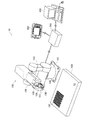
図1は、本発明の一実施形態としてのキャリブレーション装置を含むロボットシステム10の外観構成を示す説明図である。ロボットシステム10は、多関節型の産業用のロボット本体100と、制御装置200と、教示装置300と、管理用端末400とを備えている。ロボット本体100と教示装置300と管理用端末400とは、それぞれ、所定のケーブルにより制御装置200に接続されている。
A. First embodiment:
A1. System configuration:
FIG. 1 is an explanatory diagram showing an external configuration of a
教示装置300は、制御装置200に対して、ロボット本体100の動作を教示するための専用装置である。管理用端末400は、制御装置200に対して各種設定を行うための装置であり、例えば、パーソナルコンピュータにより構成することができる。
The
ロボット本体100は、ベース部101と、ショルダ部102と、下アーム103と、上アーム104と、手首105と、フランジ部106と、エンドエフェクタ107と、カメラ150とを備えている。ベース部101は、工場内の設備(例えば、工作机や床面)に固定されている。ショルダ部102は、水平方向に旋回可能な関節軸を介してベース部101に接続されている。下アーム103は、鉛直方向に旋回可能な関節軸を介して下端がショルダ部102に接続されている。上アーム104は、鉛直方向に旋回可能な関節軸を介して下アーム103の先端に略中央部が接続されている。手首105は、鉛直方向に旋回可能な関節軸を介して上アーム104の先端に接続されている。フランジ部106は、回転可能であり、手首105の先端に設けられている。エンドエフェクタ107は、フランジ部106に取り付けられ、図示しないワークを把持することができる。カメラ150は、レンズ光軸がエンドエフェクタ107の長手方向(手首105の軸方向)と平行となるように手首105に設置されている。
The
ロボットシステム10では、ワークが載置され得る作業台500の作業面S1上に載置されたキャリブレーションボードCBが撮像され、得られた画像に基づき、後述するカメラキャリブレーション処理が実行される。図1に示すように、キャリブレーションボードCBは、表面に、白色及び黒色の正方形の升目が縦及び横に交互に配置された模様を有する。かかるキャリブレーションボードCBを含む撮像画像では、同色の升目が接する点(升目の四隅)が、キャリブレーションボードCBの特徴点として抽出され得る。
In the
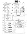
図2は、ロボットシステム10の内部構成を示すブロック図である。ロボット本体100は、三相交流式のブラシレスDCモータとして構成されたサーボモータ130と、サーボモータ130の回転を減速させる減速機120と、減速機120を介してサーボモータ130によって駆動される関節軸110と、を備えている。前述の各アーム103,104、手首105及びフランジ部106は、関節軸110に機械的に接続されている。
FIG. 2 is a block diagram showing an internal configuration of the
制御装置200は、インバータ210と、駆動回路220と、CPU(Central Processing Unit)230と、記憶部280と、入出力インターフェイス部290とを備えている。インバータ210は、駆動回路220及びロボット本体100のサーボモータ130に電気的に接続されており、駆動回路220からの駆動信号に基づき、サーボモータ130に三相交流電力を供給する。駆動回路220は、CPU230からの指示に従いインバータ210のスイッチング制御を行う。
The
CPU230は、記憶部280に記憶されている制御プログラムを実行することにより、キャリブレーション処理部231、ユーザインターフェイス(UI)制御部232、撮像制御部233、画像処理部234、および駆動制御部235として機能する。キャリブレーション処理部231は、後述するカメラキャリブレーション処理を実行する。カメラキャリブレーションとは、カメラ150による撮像対象となる物体の物理的な位置(世界座標)と、撮像画像内における物体の位置(画像座標系)とを変換するための補正値を求める処理を意味する。かかる補正値は、回転及び並進に加えて、カメラ150に含まれるレンズの歪み等を考慮した変換行列を意味する。ロボットシステム10では、カメラ150によりワークを撮像して得られた撮像画像及び補正値に基づきワークの物理的な位置を特定し、ワークの把持や移動を実行する。
The
ユーザインターフェイス制御部232は、教示装置300又は管理用端末400に各種メニュー画面を作成して表示させたり、教示装置300又は管理用端末400から入力される各種指示を解釈したりする。撮像制御部233は、撮像のための各種パラメータ(例えば、絞り値やシャッタースピード等)に従って、カメラ150に対して撮像を指示する。画像処理部234は、カメラ150による撮像によって得られた撮像画像に対して、明るさやシャープネス等を調整する。また、画像処理部234は、得られた撮像画像を解析して、後述するマスタ画像との類似度の算出や、撮像画像内の特徴点の抽出を行う。駆動制御部235は、記憶部280に予め記憶されている教示データに基づいて、サーボモータ130を駆動するための信号を駆動回路220に出力する。
The user
記憶部280は、RAM(Random Access Memory)やROM(Read Only Memory)等からなり、前述の制御プログラムを記憶すると共に、撮像画像格納部282と、マスタ画像格納部284と、補正値格納部286とを備えている。撮像画像格納部282は、カメラ150よる撮像によって得られた画像を格納する。マスタ画像格納部284は、後述するカメラキャリブレーション処理において用いられるマスタ画像を予め格納する。補正値格納部286は、後述するカメラキャリブレーション処理において算出される補正値を格納する。入出力インターフェイス部290は、カメラ150と教示装置300と管理用端末400とを、それぞれCPU230に接続させるための各種インターフェイス群からなる。
The
カメラ150は、撮像部152と、制御部154と、接続インターフェイス部156とを備えている。撮像部152は、CCD(Charge Coupled Device)等の撮像素子と、被写体の光学像を撮像面上に結像する撮像レンズ系とを備え、光学像を電気信号に変換して画像データを取得する。制御部154は、撮像制御部233からの指示に従い、撮像部を制御して、所定のシャッタースピードや絞り値で撮像を実行する。接続インターフェイス部156は、制御装置200と接続するためのインターフェイスを有する。かかるインターフェイスとしては、例えば、USB(Universal Serial Bus)や、Ethernet(登録商標)を採用することができる。
The
上記構成を有するロボットシステム10では、後述するカメラキャリブレーション処理を実行することにより、短期間のうちにキャリブレーション精度を向上させることができる。なお、ロボットシステム10では、カメラ150の位置を固定して、キャリブレーションボードCBを移動させることにより、撮像領域内において互いに異なる位置にキャリブレーションボードCBが写った複数の画像を取得し、かかる複数の画像を用いてカメラキャリブレーションが実行される。
In the
前述のキャリブレーション処理部231と画像処理部234と管理用端末400とは、請求項におけるキャリブレーション装置に相当する。キャリブレーション処理部231は、請求項におけるキャリブレーション処理部と、類似度算出部と、分類部と、判定部と、統計処理部とに相当する。管理用端末400(管理用端末400が有する表示部)は、請求項における表示部に相当する。
The
A2.カメラキャリブレーション処理:
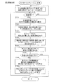
図3は、第1実施形態におけるカメラキャリブレーション処理の手順を示すフローチャートである。ユーザが管理用端末400においてカメラキャリブレーション処理メニューを選択して実行することにより、カメラキャリブレーション処理が開始される。
A2. Camera calibration process:
FIG. 3 is a flowchart showing the procedure of the camera calibration process in the first embodiment. When the user selects and executes the camera calibration process menu on the
キャリブレーション処理部231は、ユーザインターフェイス制御部232を制御して、所定数以上の撮像を指示するメッセージを管理用端末400に表示させる(ステップS105)。ユーザは、作業台500の作業面S1においてキャリブレーションボードCBを任意の位置に配置しながら、管理用端末400を操作してカメラ150による撮像を指示する。このとき、ユーザは、キャリブレーションボードCBを作業面S1上において鉛直方向に傾けて配置することもできる。撮像する所定数としては、任意の数が設定可能であるが、以下では60枚に設定されているものとして説明する。制御装置200において、撮像制御部233は、管理用端末400から撮像指示を受けると、カメラ150に対して所定の撮像条件での撮像を指示する。カメラ150において、制御部154は、撮像制御部233から撮像指示を受けると、撮像部152を制御して撮像を実行する。
The
キャリブレーション処理部231は、管理用端末400から撮像完了の通知を受けるまで待機する(ステップS110)。ユーザは、所定数以上の撮像が完了すると、管理用端末400を操作して撮像完了を制御装置200に通知する。キャリブレーション処理部231は、撮像完了の通知を受けると(ステップS110:YES)、画像処理部234を制御して、各撮像画像についてマスタ画像格納部284に格納されている複数のマスタ画像のそれぞれとの類似度を算出する(ステップS115)。
The
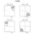
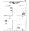
図4は、マスタ画像格納部284に格納されているマスタ画像の一例を示す説明図である。図4に示すように、第1実施形態では、4つのマスタ画像FA,FB,FC,FDが、マスタ画像格納部284に格納されている。なお、図4では、各マスタ画像FA,FB,FC,FDにおいて、説明の便宜上、画像の縦及び横の中央を示す破線を記載している。
FIG. 4 is an explanatory diagram illustrating an example of a master image stored in the master
マスタ画像FA,FB,FC,FDは、これら4つの画像に基づきカメラキャリブレーションを行った場合に、キャリブレーション精度が所定値以上(誤差が所定値以下)となる画像群である。これらのマスタ画像FA,FB,FC,FDは、予めユーザが実験によりカメラキャリブレーションを実行し、キャリブレーション精度が所定値以上となる組合せを抽出して設定することができる。なお、キャリブレーション精度については後述する。 The master images FA, FB, FC, and FD are image groups in which the calibration accuracy is equal to or higher than a predetermined value (error is equal to or lower than a predetermined value) when camera calibration is performed based on these four images. The master images FA, FB, FC, and FD can be set by extracting a combination in which the user performs camera calibration by experiments in advance and the calibration accuracy is equal to or greater than a predetermined value. The calibration accuracy will be described later.
図4に示すように、各マスタ画像FA,FB,FC,FDでは、キャリブレーションボードCBの画像CBfが、撮像領域において互いに異なる領域に写っている。具体的には、マスタ画像FAでは、画像CBfが右上の領域に写っている。マスタ画像FBでは、画像CBfが右下の領域に写っている。マスタ画像FCでは、画像CBfが左上の領域に写っている。マスタ画像FDでは、画像CBfが左下の領域に写っている。このように画像CBfが撮像領域全体に散らばって写った複数の画像を用いることで、キャリブレーション精度を向上させることができる。また、このようなマスタ画像に類似する画像を撮像により得ることができれば、得られた画像に基づきカメラキャリブレーションを行った場合にキャリブレーション精度を向上させることができる。 As shown in FIG. 4, in each of the master images FA, FB, FC, and FD, the image CBf of the calibration board CB is shown in different areas in the imaging area. Specifically, in the master image FA, the image CBf is shown in the upper right area. In the master image FB, the image CBf is shown in the lower right area. In the master image FC, the image CBf is shown in the upper left area. In the master image FD, the image CBf is shown in the lower left area. In this way, the calibration accuracy can be improved by using a plurality of images in which the image CBf is scattered throughout the imaging region. Further, if an image similar to such a master image can be obtained by imaging, the calibration accuracy can be improved when camera calibration is performed based on the obtained image.
類似度の算出は、例えば、撮像画像とマスタ画像とで、同じ位置の画素の輝度値の差分を求め、差分の合計値として算出することができる。この場合、差分の合計値が大きいほど類似度は低く、差分の合計値が小さいほど類似度は高い。 The similarity can be calculated, for example, by calculating a difference between luminance values of pixels at the same position between the captured image and the master image and calculating the difference as a total value. In this case, the greater the difference total value, the lower the similarity, and the smaller the difference difference, the higher the similarity.
キャリブレーション処理部231は、ステップS115において得られた類似度に基づき、各撮像画像を、最も類似度の高いマスタ画像のグループに分類する(ステップS120)。なお、図4に示すように、マスタ画像FAが最も類似度が高いと評価された画像群の属するグループを、以降では「グループA」と呼ぶ。同様に、マスタ画像FBが最も類似度が高いと評価された画像群の属するグループを「グループB」と、マスタ画像FCが最も類似度が高いと評価された画像群の属するグループを「グループC」と、マスタ画像FDが最も類似度が高いと評価された画像群の属するグループを「グループD」と、それぞれ以降において呼ぶものとする。
The
キャリブレーション処理部231は、ステップS120で分類された各グループ内において、類似度が最も高い撮像画像を特定する(ステップS125)。
The
キャリブレーション処理部231は、ステップS125において特定された撮像画像群(各グループ1枚ずつの合計4つの画像)を用いてカメラキャリブレーションを実行する(ステップS130)。
The
カメラキャリブレーションは、例えば、以下のように行うことができる。まず、キャリブレーションボードCBにおける同色の升目の各接点(以下、「交点」と呼ぶ)について、世界座標系における位置(座標)を特定すると共に、各交点の撮像画像における位置(画像座標系における位置)を特定する。次に、特定された各交点の世界座標系における位置(座標)及び撮像画像における位置を下記式1に当てはめて得られた複数の式を解くことにより、下記式1における回転行列及び並進ベクトル(補正値)を求める。 Camera calibration can be performed as follows, for example. First, for each contact point (hereinafter referred to as an “intersection point”) of the same color in the calibration board CB, a position (coordinate) in the world coordinate system is specified, and a position in the captured image of each intersection point (a position in the image coordinate system) ). Next, by solving a plurality of expressions obtained by applying the position (coordinates) of each specified intersection point in the world coordinate system and the position in the captured image to the following expression 1, a rotation matrix and a translation vector ( Correction value).
T=A・[R|t]・S ・・・(1) T = A · [R | t] · S (1)
上記式1において、Sは、世界座標系における位置を表す。また、Tは、画像座標系における位置を表す。また、上記式1において、Aはカメラの内部パラメータを、Rはカメラ座標系と世界座標との間の回転行列を、tは並進ベクトルを、それぞれ表す。カメラの内部パラメータとは、カメラ150のピンホール位置を原点とするカメラ座標系と、画像座標系との対応関係を示す行列式を意味する。かかるカメラの内部パラメータは、カメラの焦点距離や、撮像素子の大きさや、レンズの歪み係数等のパラメータにより設定される既知の行列式である。
In the above formula 1, S represents a position in the world coordinate system. T represents a position in the image coordinate system. In Equation 1, A represents an internal parameter of the camera, R represents a rotation matrix between the camera coordinate system and the world coordinates, and t represents a translation vector. The camera internal parameter means a determinant indicating a correspondence relationship between the camera coordinate system having the pinhole position of the
キャリブレーション処理部231は、ステップS130により得られた補正値を用いて世界座標系と画像座標系との間の変換を行った場合の誤差を求める(ステップS135)。具体的には、前述のカメラキャリブレーションにおいて特定された撮像画像における特徴点の位置に基づき上記式1の逆変換を行って得られた位置(世界座標系における座標)と、前述のカメラキャリブレーションにおいて特定された世界座標系における特徴点の位置(世界座標系における座標)とを比較して、これら位置の誤差(位置間の距離)を求める。なお、かかる誤差が小さいほどカメラキャリブレーションの精度は高い。
The
キャリブレーション処理部231は、ステップS135で求めた誤差が所定値以下であるか否かを判定し(ステップS140)、誤差が所定値以下であると判定された場合には、カメラキャリブレーション処理は終了する。カメラキャリブレーション処理が終了すると、ステップS130で求められた補正値が、その後、ロボット本体100を動作させる際に用いられることとなる。
The
前述のステップS140において、誤差が所定値よりも大きいと判定された場合には(ステップS140:NO)、キャリブレーション処理部231は、各グループに所属する画像数を特定する(ステップS145)。なお、ステップS140における「所定値」としては任意の値が設定することができ、例えば、1mmに設定することができる。
If it is determined in step S140 described above that the error is larger than the predetermined value (step S140: NO), the
キャリブレーション処理部231は、ユーザインターフェイス制御部232を制御して、所属する画像数の最も少ないグループを示す情報、およびかかるグループに属する画像の取得を促すメッセージを、管理用端末400に表示させる(ステップS150)。
The
図5は、ステップS150において表示される情報の一例を示す説明図である。例えば、所属する画像数が最も少ないグループがグループAであった場合には、ステップS150が実行されると、図5に示すウィンドウW1が表示される。第1実施形態では、ステップS150における「所属する画像数の最も少ないグループを示す情報」として、各グループのマスタ画像が表示される。したがって、図5に示すように、ウィンドウW1には、マスタ画像FAが表示されている。また、ウィンドウW1には、「以下のマスタ画像に類似する画像を10枚撮像してください」とのメッセージが表示されている。かかるメッセージを見たユーザは、マスタ画像FAに類似する画像を得るために、キャリブレーションボードCBを作業台500において右上に配置して10枚撮像を行う。なお、10枚に限らず任意の枚数の撮像を促すメッセージを採用することもできる。 FIG. 5 is an explanatory diagram illustrating an example of information displayed in step S150. For example, when the group with the smallest number of images belonging to is group A, when step S150 is executed, a window W1 shown in FIG. 5 is displayed. In the first embodiment, the master image of each group is displayed as “information indicating the group having the smallest number of images to which it belongs” in step S150. Therefore, as shown in FIG. 5, the master image FA is displayed in the window W1. In the window W1, a message “Please take 10 images similar to the following master image” is displayed. In order to obtain an image similar to the master image FA, the user who has seen such a message places the calibration board CB on the upper right of the work table 500 and takes 10 images. Note that a message that prompts an arbitrary number of images, not limited to ten, may be employed.
前述のステップS150が実行された後、前述のステップS110に戻る。したがって、今度は、追加して撮像して得られた10枚の画像を含む撮像画像群(合計70枚の撮像画像)に基づき、上述したステップS115〜S150が実行される。このようにして、ステップS140において誤差が所定値以下であると判定されるまで画像が追加されてカメラキャリブレーションが実行され、ステップS140において誤差が所定値以下であると判定されるとカメラキャリブレーション処理は終了する。 After step S150 is executed, the process returns to step S110. Therefore, this time, steps S115 to S150 described above are executed based on a group of captured images including a total of 10 captured images (70 captured images in total). In this manner, an image is added and camera calibration is executed until it is determined in step S140 that the error is equal to or smaller than the predetermined value. If it is determined in step S140 that the error is equal to or smaller than the predetermined value, camera calibration is performed. The process ends.
以上説明した第1実施形態のロボットシステム10では、所属する撮像画像数が最も少ないグループを示す情報及びかかるグループに属する画像の取得を促すメッセージを管理用端末400に表示させる。したがって、ユーザに対して所属する撮像画像数が最も少ないグループにおいて画像を追加させることができる。所属する撮像画像数が最も少ないグループに画像が追加されると、既に当該グループに所属している画像(既存画像)が少ないことから、新規に追加された画像(追加画像)は、既存画像と相違する可能性が高くなる。そして、既存画像では、「補正値による変換の誤差が所定値よりも大きい」という状態を前提に、キャリブレーション精度の改善を目指して追加画像を撮像することになるのであるから、追加画像は、当然ながら既存画像よりもマスタ画像に対する類似度の高い画像である可能性が高い。よって、画像を追加させることにより、既存画像を用いた場合に比べてキャリブレーション精度を向上させることができる。
In the
B.第2実施形態:
図6は、第2実施形態におけるカメラキャリブレーション処理の手順を示すフローチャートである。第2実施形態のロボットシステムは、カメラキャリブレーション処理において、ステップS105に代えてステップS105aを実行する点と、ステップS145に代えてステップS146を実行する点と、ステップS150に代えてステップS150aを実行する点において、第1実施形態のロボットシステム10と異なり、装置構成及びカメラキャリブレーション処理における他の手順は、第1実施形態のロボットシステム10と同じである。また、第2実施形態のロボットシステムの装置構成は、第1実施形態のロボットシステム10の装置構成と同じである。
B. Second embodiment:
FIG. 6 is a flowchart illustrating a procedure of camera calibration processing in the second embodiment. The robot system according to the second embodiment performs step S105a instead of step S105, step S146 instead of step S145, and step S150a instead of step S150 in the camera calibration process. In this respect, unlike the
第1実施形態のカメラキャリブレーション処理では、予め比較的多い撮像画像を得ておき(ステップS105)、キャリブレーション精度が低い(誤差が大きい)場合に追加して撮像画像を得るようにしていた。これに対して、第2実施形態のカメラキャリブレーション処理では、予め比較的少ない(グループ数分の)撮像画像を得ておき、キャリブレーション精度が低い(誤差が大きい)場合に1枚ずつ撮像してカメラキャリブレーション(ステップS130)を実行する。 In the camera calibration process of the first embodiment, a relatively large number of captured images are obtained in advance (step S105), and a captured image is additionally obtained when the calibration accuracy is low (error is large). On the other hand, in the camera calibration process of the second embodiment, captured images are obtained in advance (relative to the number of groups), and images are taken one by one when the calibration accuracy is low (the error is large). Then, camera calibration (step S130) is executed.
具体的には、キャリブレーション処理部231は、ユーザインターフェイス制御部232を制御して、マスタ画像と、各グループごとに1枚ずつの撮像画像を得る旨を指示するメッセージとを管理用端末400に表示させる(ステップS105a)。
Specifically, the
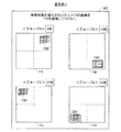
図7は、ステップS105aにおいて管理用端末400に表示される情報の一例を示す説明図である。図7に示すように、管理用端末400に表示されるウィンドウW2には、図4に示すマスタ画像と同じマスタ画像が表わされていると共に、「各マスタ画像に類似する画像を1枚ずつ撮像してください。」というメッセージが表されている。したがって、ユーザは、かかる情報を見ることにより、各マスタ画像に類似する合計4枚の撮像画像を撮像することができる。
FIG. 7 is an explanatory diagram illustrating an example of information displayed on the
ステップS105aが実行された後、上述したステップS110〜S140が実行される。なお、最初にステップS110〜S140が実行される場合には、ステップS105aの後に撮像された4枚を用いてカメラキャリブレーション(ステップS130)が実行される。 After step S105a is executed, steps S110 to S140 described above are executed. When Steps S110 to S140 are executed first, camera calibration (Step S130) is executed using the four images taken after Step S105a.
ステップS140において、ステップS135で求めた誤差が所定値よりも大きいと判定された場合には、キャリブレーション処理部231は、各グループにおいて類似度が最も高い撮像画像のうち、類似度が最も低い撮像画像が所属するグループを特定する(ステップS146)。
If it is determined in step S140 that the error obtained in step S135 is greater than the predetermined value, the
キャリブレーション処理部231は、ユーザインターフェイス制御部232を制御して、ステップS146において特定されたグループを示す情報およびかかるグループに属する画像の取得を促すメッセージを管理用端末400に表示させる(ステップS150a)。
The
図8は、ステップS150aにおいて表示される情報の一例を示す説明図である。例えば、各グループにおいて類似度が最も高い撮像画像のうち、類似度が最も低い撮像画像が所属するグループがグループAの場合には、管理用端末400に表示されるウィンドウW1aには、図5に示すウィンドウW1と同様に、マスタ画像FAが表示される。また、ウィンドウW1aには、ウィンドウW1と異なり、マスタ画像FAに類似する画像を「1枚」撮像することを指示する(促す)メッセージが表示される。したがって、ユーザは、ウィンドウW1aを見た後、キャリブレーションボードCBの配置位置を調整して、マスタ画像FAに類似する(グループAに分類される可能性が高い)画像を1枚取得する。
FIG. 8 is an explanatory diagram illustrating an example of information displayed in step S150a. For example, when the group to which the captured image with the lowest similarity belongs is group A among the captured images with the highest similarity in each group, the window W1a displayed on the
ステップS150aが実行された後、ステップS110に戻り、再びステップS110〜S150aが実行される。 After step S150a is executed, the process returns to step S110, and steps S110 to S150a are executed again.
以上の構成を有する第2実施形態のロボットシステムは、第1実施形態のロボットシステム10と同様な効果を有する。加えて、第2実施形態のカメラキャリブレーション処理では、最初に得られた4枚の撮像画像を用いてカメラキャリブレーションを実行した結果、キャリブレーション精度が所定値以下の場合(変換の誤差が所定値よりも大きい場合)には、撮像画像を1枚追加するたびにカメラキャリブレーションを実行する(ステップS130)。したがって、予め多数の撮像画像を取得しておく必要がなく、また、最少でグループ数分の撮像画像を得るだけでカメラキャリブレーション処理を完了できるので、撮像画像を得るためのユーザの作業負担を軽減することができる。
The robot system of the second embodiment having the above configuration has the same effects as the
C.変形例:
C1.変形例1:
図9は、変形例1におけるカメラキャリブレーション処理のステップS150において管理用端末400に表示される情報の一例を示す説明図である。上述した第1実施形態では、カメラキャリブレーション処理のステップS150では、所属する撮像画像数が最も少ないグループを示す情報としてマスタ画像を表示していたが、本発明はこれに限定されるものではない。例えば、図9のウィンドウW3に示すように、各マスタ画像FA,FB,FC,FDと、各マスタ画像のグループに所属している撮像画像数とを、表示することができる。具体的には、図8に示すように、マスタ画像FAの近傍に、グループAに所属する撮像画像数「8枚」を表示することができる。同様に、マスタ画像FBの近傍にグループBに所属する撮像画像数「12枚」を、マスタ画像FCの近傍にグループCに所属する撮像画像数「25枚」を、マスタ画像FDの近傍にグループDに所属する撮像画像数「15枚」を、それぞれ表示することができる。また、ウィンドウW3には、「撮像枚数の最も少ないグループの画像を10枚撮像してください」とのメッセージが表示されている。このようなウィンドウW3を表示させることにより、グループAに所属する撮像画像の数が他のグループに比べて少ないこと、及びグループAに所属するような画像を撮像する必要があることをユーザに理解させることができる。
C. Variations:
C1. Modification 1:
FIG. 9 is an explanatory diagram showing an example of information displayed on the
C2.変形例2:
図10は、変形例2におけるカメラキャリブレーション処理の手順を示すフローチャートである。変形例2のカメラキャリブレーション処理は、ステップS145に代えてステップS146を実行する点、及びステップS150に代えてステップS150aを実行する点において、図3に示す第1実施形態のカメラキャリブレーション処理と異なり、他の手順は、第1実施形態と同じである。また、変形例2におけるロボットシステムの装置構成は、第1実施形態のロボットシステム10の装置構成と同じである。
C2. Modification 2:
FIG. 10 is a flowchart illustrating a procedure of camera calibration processing according to the second modification. The camera calibration process of the second modified example is different from the camera calibration process of the first embodiment shown in FIG. 3 in that step S146 is executed instead of step S145 and step S150a is executed instead of step S150. Differently, other procedures are the same as those in the first embodiment. Further, the device configuration of the robot system in Modification 2 is the same as the device configuration of the
ステップS146は、図6に示す第2実施形態のカメラキャリブレーション処理のステップS146と同じである。同様に、ステップS150aは、図6に示す第2実施形態のカメラキャリブレーション処理のステップS150aと同じである。 Step S146 is the same as step S146 of the camera calibration process of the second embodiment shown in FIG. Similarly, step S150a is the same as step S150a of the camera calibration process of the second embodiment shown in FIG.
以上の構成を有する変形例2のロボットシステムでは、各グループにおける類似度が最も高い撮像画像のうち、類似度が最も低い撮像画像のグループについて、かかるグループを示す情報及びかかるグループに属する画像の取得を促すメッセージを管理用端末400に表示させるので、かかるグループに属する画像数の増加を促すことができる。このため、かかるグループにおいて類似度が最も高い撮像画像の類似度が上昇する可能性を高めることができ、キャリブレーション精度を向上させることができる。なお、変形例2において、変形1と同様に、各マスタ画像FA,FB,FC,FDを表示させると共に、各グループA〜Dにおける類似度が最も高い撮像画像の類似度を、各マスタ画像FA,FB,FC,FDに対応付けて表示させることもできる。
In the robot system according to the second modification having the above-described configuration, information indicating the group and acquisition of an image belonging to the group of the captured image with the lowest similarity among the captured images with the highest similarity in each group. Is displayed on the
C3.変形例3:
図11は、変形例3におけるカメラキャリブレーション処理の手順を示すフローチャートである。変形例3のカメラキャリブレーション処理は、ステップS150に代えてステップS150bを実行する点において、図3に示す第1実施形態のカメラキャリブレーション処理と異なり、他の手順は第1実施形態と同じである。また、変形例2におけるロボットシステムの装置構成は、第1実施形態のロボットシステム10の装置構成と同じである。
C3. Modification 3:
FIG. 11 is a flowchart illustrating a procedure of camera calibration processing according to the third modification. The camera calibration process of Modification 3 is different from the camera calibration process of the first embodiment shown in FIG. 3 in that step S150b is executed instead of step S150, and other procedures are the same as those of the first embodiment. is there. Further, the device configuration of the robot system in Modification 2 is the same as the device configuration of the
変形例3のカメラキャリブレーション処理では、ステップS145が実行された後、キャリブレーション処理部231は、ユーザインターフェイス制御部232を制御して、所属する画像数の最も少ないグループを示す情報と、かかるグループに属する画像の取得を促すメッセージと、ステップS135で求めた誤差とを、管理用端末400に表示させる(ステップS150b)。
In the camera calibration process of the third modification, after step S145 is executed, the
図12は、変形例3のステップS150bにおいて表示される情報の一例を示す説明図である。図12に示すように、管理用端末400に表示されるウィンドウW4は、誤差表示領域Arが設けられている点において、図5に示すウィンドウW1と異なり、他の構成はウィンドウW1と同じである。誤差表示領域Arは、ステップS135において求められた誤差を表示するための領域である。図5の例では、誤差として「1.5mm」が表示されている。
FIG. 12 is an explanatory diagram illustrating an example of information displayed in step S150b of the third modification. As shown in FIG. 12, the window W4 displayed on the
以上の構成を有する変形例3のロボットシステムは、第1実施形態のロボットシステム10と同様の効果を有する。加えて、管理用端末400において、ステップS135で求めた誤差を表示するので、ユーザに対してキャリブレーション精度がどの程度であるかを理解させることができる。したがって、ユーザは、キャリブレーションボードCBの位置を調整した際に、キャリブレーション精度が向上したのか又は低下したのかを理解することができ、誤差表示領域Arに表示される数値(誤差)を、キャリブレーションボードCBの位置をずらす際の目安とすることができる。
The robot system of Modification 3 having the above configuration has the same effects as the
C4.変形例4:
図13は、変形例4におけるカメラキャリブレーション処理の手順を示すフローチャートである。変形例4のカメラキャリブレーション処理は、ステップS147を追加して実行する点、およびステップS150に代えてステップS150cを実行する点において、図3に示す第1実施形態のカメラキャリブレーション処理と異なり、他の手順は、第1実施形態と同じである。また、変形例4におけるロボットシステムの装置構成は、第1実施形態のロボットシステム10の装置構成と同じである。
C4. Modification 4:
FIG. 13 is a flowchart illustrating a procedure of camera calibration processing according to the fourth modification. The camera calibration process of Modification 4 differs from the camera calibration process of the first embodiment shown in FIG. 3 in that step S147 is added and executed, and step S150c is executed instead of step S150. Other procedures are the same as those in the first embodiment. Further, the device configuration of the robot system in Modification 4 is the same as the device configuration of the
変形例4のカメラキャリブレーション処理では、上述したステップS145が実行された後、キャリブレーション処理部231は、ステップS115において算出した各撮像画像の類似度に基づき各グループの平均類似度を求める(ステップS147)。キャリブレーション処理部231は、ユーザインターフェイス制御部232を制御して、各グループの撮像画像数、最高類似度、平均類似度のヒストグラムを管理用端末400に表示させる(ステップS150c)。
In the camera calibration process of the modified example 4, after the above-described step S145 is executed, the
図14は、変形例4のステップS150cにおいて表示される情報の一例を示す説明図である。図14に示すように、管理用端末400に表示されるウィンドウW5には、撮像画像数のヒストグラムと、最高類似度のヒストグラムと、平均類似度のヒストグラムとが表示されている。なお、図14では、類似度(最高類似度及び平均類似度)の単位はパーセンテージである。このように、管理用端末400において、撮像画像数のヒストグラムと、最高類似度のヒストグラムと、平均類似度のヒストグラムとが表示されるので、ユーザは、各グループのうち、いずれのグループに所属する撮像画像数が最も少ないのか、いずれのグループの最高類似度が最も低いのか、いずれのグループの平均類似度が最も低いのかを容易に理解することができる。したがって、例えば、ユーザは、最高類似度が最も低いグループに所属する画像を取得することにより、キャリブレーション精度を高めることができる。
FIG. 14 is an explanatory diagram illustrating an example of information displayed in step S150c of the fourth modification. As shown in FIG. 14, in the window W5 displayed on the
C5.変形例5:
図15は、変形例5のロボットシステム10aの内部構成を示すブロック図である。第1実施形態のロボットシステム10は、カメラ150を除くカメラキャリブレーション処理を実現する機能部は、いずれも制御装置200が有していたが、変形例5のロボットシステム10aでは、これら機能部を、制御装置及び管理用端末が分担して有する。
C5. Modification 5:
FIG. 15 is a block diagram illustrating an internal configuration of the
具体的には、変形例5の制御装置200aは、CPU230が、キャリブレーション処理部231,ユーザインターフェイス制御部232,撮像制御部233、及び画像処理部234として機能しない点と、駆動制御部235に代えて駆動副制御部236として機能する点とにおいて、第1実施形態の制御装置200と異なり、他の構成は、制御装置200と同じである。駆動副制御部236は、後述する管理用端末400aから受信する信号を駆動回路220に供給する。
Specifically, in the
変形例5の管理用端末400aは、コンピュータ本体401と、ディスプレイ460と、キーボード470とを備えている。コンピュータ本体401は、入出力インターフェイス部410と、CPU420と、ハードディスク430と、RAM440と、ROM450とを備えている。
The management terminal 400a according to the modified example 5 includes a computer
入出力インターフェイス部410は、各種接続インターフェイス群からなり、制御装置200aの入出力インターフェイス部290と、カメラ150の接続インターフェイス部156と、ディスプレイ460と、キーボード470と、CPU420とに接続されている。CPU420は、ROM450に記憶されている制御プログラムを読み出してRAM440に展開して実行することにより、キャリブレーション処理部421,撮像制御部422,駆動主制御部423,ユーザインターフェイス制御部424,及び画像処理部425として機能する。キャリブレーション処理部421は、第1実施形態におけるキャリブレーション処理部231と同じであるので説明を省略する。同様に、撮像制御部422は第1実施形態における撮像制御部233と、ユーザインターフェイス制御部424は第1実施形態におけるユーザインターフェイス制御部232と、画像処理部425は第1実施形態における画像処理部234と、それぞれ同じであるので説明を省略する。駆動主制御部423は、ROM450に予め記憶されている教示データに基づき、サーボモータ130を駆動するための信号を駆動副制御部236に送信する。
The input /
ハードディスク430は、撮像画像格納部431とマスタ画像格納部432と補正値格納部433とを備えている。撮像画像格納部431は、第1実施形態における撮像画像格納部282と同じであるので説明を省略する。同様に、マスタ画像格納部432は第1実施形態におけるマスタ画像格納部284と、補正値格納部433は第1実施形態における補正値格納部286と、それぞれ同じであるので説明を省略する。
The
以上の構成を有する変形例5のロボットシステム10aは、第1実施形態のロボットシステム10と同様の効果を有する。
The
C6.変形例6:
図16は、変形例6のロボットシステム10bの内部構成を示すブロック図である。変形例6のロボットシステム10bは、管理用端末400を有していない点、カメラ150に代えてカメラ150aを有する点、及び制御装置200が有する一部の機能部が省略されている点において、第1実施形態のロボットシステム10と異なり、他の構成及びカメラキャリブレーション処理の手順は、第1実施形態のロボットシステム10と同じである。
C6. Modification 6:
FIG. 16 is a block diagram illustrating an internal configuration of the
変形例6の制御装置200aは、図15に示す変形例5の制御装置200と同じであるので、説明を省略する。
The
変形例6のカメラ150aは、CPU160と記憶部170と操作部180と表示部182とを備えている点、及び接続インターフェイス部156の接続先が制御部154に代えてCPU160である点において、第1実施形態のカメラ150と異なり、他の構成は、第1実施形態のカメラ150と同じである。
The
CPU160は、記憶部170に記憶されている制御プログラムを実行することにより、キャリブレーション処理部161,撮像制御部162,駆動主制御部163,ユーザインターフェイス制御部164,及び画像処理部165として機能する。キャリブレーション処理部161は、第1実施形態におけるキャリブレーション処理部231と同じであるので説明を省略する。同様に、撮像制御部162は第1実施形態における撮像制御部233と、駆動主制御部163は第2実施形態における駆動主制御部423と、ユーザインターフェイス制御部164は第1実施形態におけるユーザインターフェイス制御部232と、画像処理部165は第1実施形態における撮像制御部233と、それぞれ同じであるので説明を省略する。
The
記憶部170は、RAMやROM等からなり、前述の制御プログラムを記憶すると共に、撮像画像格納部171とマスタ画像格納部172と補正値格納部173とを備えている。撮像画像格納部171は、第1実施形態における撮像画像格納部282と同じであるので説明を省略する。同様に、マスタ画像格納部172は第1実施例のマスタ画像格納部284と、補正値格納部173は第1実施形態における補正値格納部286と、それぞれ同じであるので説明を省略する。
The
操作部180は、CPU160と接続されている。操作部180は各種操作ボタンを有しており、操作ボタンを介して入力される指示をCPU160に通知する。表示部182はCPU160と接続されており、ユーザインターフェイス制御部164により生成された各種メニュー画面や各種ウィンドウ等を表示する。
The
以上の構成を有する変形例6のロボットシステム10bは、第1実施形態のロボットシステム10と同様の効果を有する。加えて、管理用端末400を省略することができるので、システム全体を小型化することができる。
The
C7.変形例7:
各実施形態及び各変形例では、カメラキャリブレーションに用いる撮像画像の数は4枚であったが、4枚に限らず任意の複数枚とすることもできる。例えば、カメラ150の撮像領域を6つに分割して、分割されたそれぞれの領域にキャリブレーションボードCBが写った撮像画像をカメラキャリブレーションに用いることができる。この構成では、マスタ画像は6枚用意され、撮像画像は6つのグループに分類されることとなる。
C7. Modification 7:
In each embodiment and each modification, the number of captured images used for camera calibration is four. However, the number is not limited to four, and may be any plural number. For example, the imaging area of the
C8.変形例8:
変形例4を除く各実施形態及び各変形例おいて、管理用端末400に表示される「グループを示す情報」には、マスタ画像が含まれていたが、マスタ画像を省略することができる。この場合、グループを示す情報として、例えば、グループ名を表示することもできる。
C8. Modification 8:
In each embodiment and each modification excluding the modification 4, the “information indicating a group” displayed on the
C9.変形例9:
第1実施形態のステップS150において、撮像画像数が最も少ないグループを示す情報及び画像取得を促すメッセージを表示するのは管理用端末400であったが、管理用端末400に代えて、教示装置300に表示させることもできる。また、制御装置200に表示部を設けて、かかる表示部に、撮像画像数が最も少ないグループを示す情報及び画像取得を促すメッセージを表示する構成を採用することもできる。
C9. Modification 9:
In step S150 of the first embodiment, the
C10.変形例10:
第1実施形態では、カメラキャリブレーション処理のステップS150において、所属する画像数が最も少ないグループを示す情報を表示していたが、これに代えて、所属する画像数が最も少ないグループと、2番目以降に少ない任意のグループを示す情報を表示することもできる。例えば、所属する画像数が最も少ないグループと2番目に少ないグループとを示す情報を表示することができる。この構成では、マスタ画像により類似する2枚の画像が次回のカメラキャリブレーションで用いられ得るので、キャリブレーション精度をより短期間に向上させることができる。
C10. Modification 10:
In the first embodiment, in step S150 of the camera calibration process, information indicating the group having the smallest number of images belonging to the group is displayed. Instead, the group having the smallest number of images belonging to the second group is displayed. Thereafter, information indicating a small number of arbitrary groups can be displayed. For example, it is possible to display information indicating the group with the fewest number of images and the second smallest group. In this configuration, two images that are more similar to the master image can be used in the next camera calibration, so that the calibration accuracy can be improved in a shorter time.
C11.変形例11:
各実施形態では、新たに撮像画像が新たに得られるたびに、補正値(ステップS130)、及び変換の誤差(ステップS135)を求めていたが、本発明はこれに限定されるものではない。例えば、ステップS130,S135,S140に代えて、以下の手順を実行することができる。まず、ステップS125において特定された撮像画像の類似度が所定値以上であるか否かを判定し、類似度が所定値以上である場合にカメラキャリブレーション処理を終了し、類似度が所定値よりも低い場合に前述のステップS145,S150を実行する、との手順を実行することができる。このような構成によれば、補正値及び誤差の算出を省略することができるので、カメラキャリブレーション処理に要する期間を短くすることができる。
C11. Modification 11:
In each embodiment, the correction value (step S130) and the conversion error (step S135) are obtained every time a new captured image is newly obtained, but the present invention is not limited to this. For example, the following procedure can be executed in place of steps S130, S135, and S140. First, it is determined whether or not the similarity of the captured image specified in step S125 is greater than or equal to a predetermined value. If the similarity is greater than or equal to a predetermined value, the camera calibration process is terminated, and the similarity is greater than the predetermined value. If the value is lower, the above-described steps S145 and S150 can be executed. According to such a configuration, calculation of the correction value and the error can be omitted, so that the period required for the camera calibration process can be shortened.
C12.変形例12:
各実施形態では、カメラ150,150aは、手首105に設置されていたが、本発明はこれに限定されるものではない。例えば、手首105に代えて、上アーム104や下アーム103やショルダ部102やフランジ部106等に配置することもできる。すなわち、一般には、ロボット本体100が有するアームと所定の位置関係となる位置に配置された撮像装置を、本発明における撮像装置として採用することができる。なお、請求項における「アーム」とは、各実施形態における下アーム103,上アーム104,手首105,フランジ部106を含む広い意味を有する。
C12. Modification 12:
In each embodiment, the
C13.変形例13:
各実施形態においてソフトウェアによって実現されていた構成の一部をハードウェアに置き換えるようにしてもよい。また、これとは逆に、ハードウェアによって実現されていた構成の一部をソフトウェアに置き換えるようにしてもよい。
C13. Modification 13:
A part of the configuration realized by software in each embodiment may be replaced with hardware. On the contrary, a part of the configuration realized by hardware may be replaced with software.
本発明は、上述の実施形態や変形例に限られるものではなく、その趣旨を逸脱しない範囲において種々の構成で実現することができる。例えば、発明の概要の欄に記載した各形態中の技術的特徴に対応する実施形態、変形例中の技術的特徴は、上述の課題の一部又は全部を解決するために、あるいは、上述の効果の一部又は全部を達成するために、適宜、差し替えや、組み合わせを行うことが可能である。また、その技術的特徴が本明細書中に必須なものとして説明されていなければ、適宜、削除することが可能である。 The present invention is not limited to the above-described embodiments and modifications, and can be realized with various configurations without departing from the spirit thereof. For example, the technical features in the embodiments and the modifications corresponding to the technical features in each embodiment described in the summary section of the invention are to solve some or all of the above-described problems, or In order to achieve part or all of the effects, replacement or combination can be performed as appropriate. Further, if the technical feature is not described as essential in the present specification, it can be deleted as appropriate.
10,10a,10b…ロボットシステム
100…ロボット本体
101…ベース部
102…ショルダ部
103…下アーム
104…上アーム
105…手首
106…フランジ部
107…エンドエフェクタ
110…関節軸
120…減速機
130…サーボモータ
150,150a…カメラ
152…撮像部
154…制御部
156…接続インターフェイス部
160…CPU
161…キャリブレーション処理部
162…撮像制御部
163…駆動主制御部
164…ユーザインターフェイス制御部
165…画像処理部
170…記憶部
171…撮像画像格納部
172…マスタ画像格納部
173…補正値格納部
180…操作部
182…表示部
200,200a…制御装置
210…インバータ
220…駆動回路
230…CPU
231…キャリブレーション処理部
232…ユーザインターフェイス制御部
233…撮像制御部
234…画像処理部
235…駆動制御部
236…駆動副制御部
280…記憶部
282…撮像画像格納部
284…マスタ画像格納部
286…補正値格納部
290…入出力インターフェイス部
300…教示装置
400,400a…管理用端末
401…コンピュータ本体
410…入出力インターフェイス部
420…CPU
421…キャリブレーション処理部
422…撮像制御部
423…駆動主制御部
424…ユーザインターフェイス制御部
430…ハードディスク
431…撮像画像格納部
432…マスタ画像格納部
433…補正値格納部
460…ディスプレイ
470…キーボード
500…作業台
S1…作業面
W1,W1a,W2,W3,W4,W5…ウィンドウ
FA,FB,FC,FD…マスタ画像
CB…キャリブレーションボード
Ar…誤差表示領域
CBf…キャリブレーションボードの画像
DESCRIPTION OF
161:
231 ...
421 ...
Claims (9)
特徴点を有するキャリブレーションボードを前記撮像装置が撮像することにより得られた複数の撮像画像のそれぞれについて、前記キャリブレーションボードが互いに異なる位置に写った複数のマスタ画像のそれぞれに対する類似度を算出する類似度算出部と、
前記算出された類似度に基づき、前記複数の撮像画像を、各マスタ画像に関連付けられた複数のグループに分類する分類部と、
前記複数のグループの各グループにおいて、前記類似度が所定値以上の代表画像を1つ抽出し、抽出された複数の前記代表画像からなる代表画像群に基づき、前記特徴点の前記キャリブレーションボードにおける物理的な位置と前記特徴点の前記撮像画像における位置とを変換するための補正値を決定するキャリブレーション処理部と、
前記決定された補正値による前記変換の誤差が、所定値以下であるか否かを判定する判定部と、
前記誤差が前記所定値よりも大きいと判定された場合に、前記複数のグループのそれぞれに分類された前記撮像画像の数に関連する撮像数関連情報を表示する表示部と、
を備える、キャリブレーション装置。 A calibration device for calibrating an imaging device arranged in a predetermined positional relationship with an arm of a robot,
For each of a plurality of captured images obtained by imaging the calibration board having feature points by the imaging device, a similarity is calculated for each of a plurality of master images in which the calibration board appears at different positions. A similarity calculator;
A classification unit that classifies the plurality of captured images into a plurality of groups associated with each master image based on the calculated similarity;
In each group of the plurality of groups, one representative image having a similarity equal to or greater than a predetermined value is extracted, and the feature point in the calibration board is based on a representative image group including the extracted plurality of representative images. A calibration processing unit that determines a correction value for converting a physical position and a position of the feature point in the captured image;
A determination unit that determines whether an error of the conversion by the determined correction value is equal to or less than a predetermined value;
A display unit that displays imaging number related information related to the number of the captured images classified into each of the plurality of groups when the error is determined to be larger than the predetermined value;
A calibration device comprising:
前記撮像数関連情報は、前記複数のグループのうち、前記分類された撮像画像の数が最も少ないグループを特定可能な情報を含む、キャリブレーション装置。 The calibration device according to claim 1,
The number-of-capturing number related information is a calibration device including information that can identify a group having the smallest number of classified captured images among the plurality of groups.
前記撮像数関連情報は、前記複数のグループのそれぞれに分類された前記撮像画像の数を示す情報を含む、キャリブレーション装置。 In the calibration apparatus according to claim 1 or 2,
The number-of-capturing number related information is a calibration device including information indicating the number of the captured images classified into each of the plurality of groups.
各グループごとに、該グループに分類された撮像画像のそれぞれについて算出された前記類似度の統計的特性を求める統計処理部を備え、
前記表示部は、前記誤差が前記所定値よりも大きい場合に、前記統計的特性に関連する統計的特性関連情報を表示する、キャリブレーション装置。 The calibration device according to any one of claims 1 to 3, further comprising:
For each group, a statistical processing unit for obtaining a statistical characteristic of the similarity calculated for each of the captured images classified into the group,
The said display part is a calibration apparatus which displays the statistical characteristic relevant information relevant to the said statistical characteristic, when the said error is larger than the said predetermined value.
前記統計的特性は、各グループに分類された撮像画像のそれぞれについて算出された前記類似度のうち最高値であり、
前記統計的特性関連情報は、前記複数のグループのうち、前記最高値が最も低いグループを特定可能な情報を含む、キャリブレーション装置。 The calibration device according to claim 4,
The statistical characteristic is the highest value among the similarities calculated for each of the captured images classified into each group,
The statistical characteristic-related information, among the plurality of groups, the maximum value including information capable of identifying the lowest group, the calibration apparatus.
前記統計的特性は、各グループに分類された撮像画像のそれぞれについて算出された前記類似度の平均値であり、
前記統計的特性関連情報は、前記複数のグループのうち、前記平均値が最も低いグループを特定可能な情報を含む、キャリブレーション装置。 The calibration device according to claim 4,
The statistical characteristic is an average value of the similarity calculated for each captured image classified into each group,
The statistical characteristic-related information, among the plurality of groups, the average value including information capable of identifying the lowest group, the calibration apparatus.
前記表示部は、前記誤差を表示する、キャリブレーション装置。 In the calibration apparatus as described in any one of Claim 1- Claim 6,
The said display part is a calibration apparatus which displays the said error.
前記撮像装置は、連続して前記撮像画像を取得し、
前記キャリブレーション処理部は、前記撮像部により前記撮像画像が取得されるたびに、得られた前記複数の撮像画像のうち、前記誤差が最も小さくなる前記代表画像群を決定する、キャリブレーション装置。 In the calibration apparatus according to any one of claims 1 to 7,
The imaging device continuously acquires the captured image,
The calibration apparatus, wherein the calibration processing unit determines the representative image group having the smallest error among the plurality of obtained captured images each time the captured image is acquired by the imaging unit.
(a)特徴点を有するキャリブレーションボードを前記撮像装置が撮像することにより得られた複数の撮像画像のそれぞれについて、前記キャリブレーションボードが互いに異なる位置に写った複数のマスタ画像のそれぞれに対する類似度を算出する工程と、
(b)前記算出された類似度に基づき、前記複数の撮像画像を、各マスタ画像に関連付けられた複数のグループに分類する工程と、
(c)前記複数のグループの各グループにおいて、前記類似度が所定値以上の代表画像を1つ抽出し、抽出された複数の前記代表画像からなる代表画像群に基づき、前記特徴点の前記キャリブレーションボードにおける物理的な位置と前記特徴点の前記撮像画像における位置とを変換するための補正値を決定する工程と、
(d)前記決定された補正値による前記変換の誤差が、所定値以下であるか否かを判定する工程と、
(e)前記誤差が前記所定値よりも大きいと判定された場合に、前記複数のグループのそれぞれに分類された前記撮像画像の数に関連する撮像数関連情報を表示する工程と、
を備える、撮像装置のキャリブレーション方法。 A calibration method for an imaging apparatus arranged in a predetermined positional relationship with an arm of a robot,
(A) For each of a plurality of captured images obtained by imaging the calibration board having feature points by the imaging device, the similarity to each of a plurality of master images in which the calibration board is located at different positions Calculating
(B) classifying the plurality of captured images into a plurality of groups associated with each master image based on the calculated similarity;
(C) In each group of the plurality of groups, one representative image having a similarity equal to or greater than a predetermined value is extracted, and the calibration of the feature points is performed based on a representative image group including the extracted plurality of representative images. Determining a correction value for converting a physical position on the motion board and a position of the feature point in the captured image;
(D) determining whether an error in the conversion due to the determined correction value is equal to or less than a predetermined value;
(E) when it is determined that the error is larger than the predetermined value, displaying imaging number related information related to the number of the captured images classified into each of the plurality of groups;
An imaging apparatus calibration method comprising:
Priority Applications (1)
| Application Number | Priority Date | Filing Date | Title |
|---|---|---|---|
| JP2012216472A JP5962394B2 (en) | 2012-09-28 | 2012-09-28 | Calibration apparatus and imaging apparatus calibration method |
Applications Claiming Priority (1)
| Application Number | Priority Date | Filing Date | Title |
|---|---|---|---|
| JP2012216472A JP5962394B2 (en) | 2012-09-28 | 2012-09-28 | Calibration apparatus and imaging apparatus calibration method |
Publications (3)
| Publication Number | Publication Date |
|---|---|
| JP2014069272A JP2014069272A (en) | 2014-04-21 |
| JP2014069272A5 JP2014069272A5 (en) | 2015-11-19 |
| JP5962394B2 true JP5962394B2 (en) | 2016-08-03 |
Family
ID=50744973
Family Applications (1)
| Application Number | Title | Priority Date | Filing Date |
|---|---|---|---|
| JP2012216472A Active JP5962394B2 (en) | 2012-09-28 | 2012-09-28 | Calibration apparatus and imaging apparatus calibration method |
Country Status (1)
| Country | Link |
|---|---|
| JP (1) | JP5962394B2 (en) |
Cited By (3)
| Publication number | Priority date | Publication date | Assignee | Title |
|---|---|---|---|---|
| CN111131813A (en) * | 2019-10-29 | 2020-05-08 | 牧今科技 | Method and system for determining pose of camera calibration |
| US11370121B2 (en) | 2019-10-29 | 2022-06-28 | Mujin, Inc. | Method and system for determining poses for camera calibration |
| WO2023208508A1 (en) * | 2022-04-27 | 2023-11-02 | TRUMPF Werkzeugmaschinen SE + Co. KG | Method for checking the calibration of an image processing system of a sheet metal working machine |
Families Citing this family (6)
| Publication number | Priority date | Publication date | Assignee | Title |
|---|---|---|---|---|
| JP5991121B2 (en) * | 2012-09-28 | 2016-09-14 | 株式会社デンソーウェーブ | Calibration apparatus and imaging apparatus calibration method |
| US10931933B2 (en) * | 2014-12-30 | 2021-02-23 | Eys3D Microelectronics, Co. | Calibration guidance system and operation method of a calibration guidance system |
| WO2018163450A1 (en) * | 2017-03-09 | 2018-09-13 | 三菱電機株式会社 | Robot control device and calibration method |
| JP6301045B1 (en) * | 2017-03-09 | 2018-03-28 | 三菱電機株式会社 | Robot control apparatus and calibration method |
| US10576636B1 (en) | 2019-04-12 | 2020-03-03 | Mujin, Inc. | Method and control system for and updating camera calibration for robot control |
| JP6785931B1 (en) * | 2019-08-30 | 2020-11-18 | Dmg森精機株式会社 | Production system |
Family Cites Families (5)
| Publication number | Priority date | Publication date | Assignee | Title |
|---|---|---|---|---|
| JPH06243236A (en) * | 1993-02-18 | 1994-09-02 | Sharp Corp | Coordinate system calibration parameter setting device for visual recognition device |
| JPH0882505A (en) * | 1994-09-12 | 1996-03-26 | Mazda Motor Corp | Calibration method of camera parameter and measuring method of object position |
| JP2010188439A (en) * | 2009-02-16 | 2010-09-02 | Mitsubishi Electric Corp | Method and apparatus for calculating parameter |
| JP5371927B2 (en) * | 2010-10-27 | 2013-12-18 | 三菱電機株式会社 | Coordinate system calibration method and robot system |
| JP5991121B2 (en) * | 2012-09-28 | 2016-09-14 | 株式会社デンソーウェーブ | Calibration apparatus and imaging apparatus calibration method |
-
2012
- 2012-09-28 JP JP2012216472A patent/JP5962394B2/en active Active
Cited By (3)
| Publication number | Priority date | Publication date | Assignee | Title |
|---|---|---|---|---|
| CN111131813A (en) * | 2019-10-29 | 2020-05-08 | 牧今科技 | Method and system for determining pose of camera calibration |
| US11370121B2 (en) | 2019-10-29 | 2022-06-28 | Mujin, Inc. | Method and system for determining poses for camera calibration |
| WO2023208508A1 (en) * | 2022-04-27 | 2023-11-02 | TRUMPF Werkzeugmaschinen SE + Co. KG | Method for checking the calibration of an image processing system of a sheet metal working machine |
Also Published As
| Publication number | Publication date |
|---|---|
| JP2014069272A (en) | 2014-04-21 |
Similar Documents
| Publication | Publication Date | Title |
|---|---|---|
| JP5962394B2 (en) | Calibration apparatus and imaging apparatus calibration method | |
| CN111151463B (en) | Mechanical arm sorting and grabbing system and method based on 3D vision | |
| US8135173B2 (en) | Eye-tracking method and eye-tracking system for implementing the same | |
| US7911500B2 (en) | Image processing device, computer readable recording medium, and image processing method | |
| CN109052180B (en) | A method and system for automatic container alignment based on machine vision | |
| JP4692632B2 (en) | Image processing method, image processing program, and image processing apparatus | |
| US9595095B2 (en) | Robot system | |
| US11202010B2 (en) | Control device, external device, medical observation system, control method, display method, and program | |
| JP2012010275A (en) | Information processing device, information processing method and program thereof | |
| US20160093028A1 (en) | Image processing method, image processing apparatus and electronic device | |
| JP2014029664A (en) | Image comparison range generation method, positional orientation detection method, image comparison range generation device, positional orientation detection device, robot, robot system, image comparison range generation program and positional orientation detection program | |
| US20180215044A1 (en) | Image processing device, robot control device, and robot | |
| CN112351325B (en) | Gesture-based display terminal control method, terminal and readable storage medium | |
| JP5991121B2 (en) | Calibration apparatus and imaging apparatus calibration method | |
| JP6178646B2 (en) | Imaging apparatus and image shake correction processing method | |
| JPH01134573A (en) | Image processing method | |
| JP2008217330A (en) | Speed estimation method and speed estimation program | |
| JP2011175347A (en) | Information processing apparatus and method | |
| JP2003028812A (en) | X-ray fluoroscope | |
| EP3026888B1 (en) | Focus control device, program for focus control, and method for focus control | |
| JP2014006852A (en) | Recognition processing method, recognition processing device, robot system and recognition processing program | |
| JP2025060252A (en) | Information processing device, system, control device, control method, and program | |
| JP2015136763A (en) | Control device, robot system, robot, and robot control method | |
| JP2015076026A (en) | Pattern matching apparatus and pattern matching method | |
| JP2022065782A (en) | Registration device, operation device, registration method, operation method, program, and recording medium |
Legal Events
| Date | Code | Title | Description |
|---|---|---|---|
| A621 | Written request for application examination |
Free format text: JAPANESE INTERMEDIATE CODE: A621 Effective date: 20150804 |
|
| A521 | Request for written amendment filed |
Free format text: JAPANESE INTERMEDIATE CODE: A523 Effective date: 20151001 |
|
| A977 | Report on retrieval |
Free format text: JAPANESE INTERMEDIATE CODE: A971007 Effective date: 20160525 |
|
| TRDD | Decision of grant or rejection written | ||
| A01 | Written decision to grant a patent or to grant a registration (utility model) |
Free format text: JAPANESE INTERMEDIATE CODE: A01 Effective date: 20160531 |
|
| A61 | First payment of annual fees (during grant procedure) |
Free format text: JAPANESE INTERMEDIATE CODE: A61 Effective date: 20160613 |
|
| R150 | Certificate of patent or registration of utility model |
Ref document number: 5962394 Country of ref document: JP Free format text: JAPANESE INTERMEDIATE CODE: R150 |
|
| R250 | Receipt of annual fees |
Free format text: JAPANESE INTERMEDIATE CODE: R250 |
|
| R250 | Receipt of annual fees |
Free format text: JAPANESE INTERMEDIATE CODE: R250 |
|
| R250 | Receipt of annual fees |
Free format text: JAPANESE INTERMEDIATE CODE: R250 |
|
| R250 | Receipt of annual fees |
Free format text: JAPANESE INTERMEDIATE CODE: R250 |
|
| R250 | Receipt of annual fees |
Free format text: JAPANESE INTERMEDIATE CODE: R250 |
|
| R250 | Receipt of annual fees |
Free format text: JAPANESE INTERMEDIATE CODE: R250 |
|
| R250 | Receipt of annual fees |
Free format text: JAPANESE INTERMEDIATE CODE: R250 |