JP5962217B2 - printer - Google Patents
printer Download PDFInfo
- Publication number
- JP5962217B2 JP5962217B2 JP2012122799A JP2012122799A JP5962217B2 JP 5962217 B2 JP5962217 B2 JP 5962217B2 JP 2012122799 A JP2012122799 A JP 2012122799A JP 2012122799 A JP2012122799 A JP 2012122799A JP 5962217 B2 JP5962217 B2 JP 5962217B2
- Authority
- JP
- Japan
- Prior art keywords
- printer
- paper
- main body
- printer main
- label
- Prior art date
- Legal status (The legal status is an assumption and is not a legal conclusion. Google has not performed a legal analysis and makes no representation as to the accuracy of the status listed.)
- Expired - Fee Related
Links
Images


Landscapes
- Accessory Devices And Overall Control Thereof (AREA)
- Printers Characterized By Their Purpose (AREA)
Description
本発明は、表示や操作入力が可能なパネルを備えたインクジェットプリンター等のプリンターに関する。 The present invention relates to a printer such as an ink jet printer provided with a panel capable of display and operation input.
プリンターとしては、パーソナルコンピューターに接続せずに単独で使用可能なものが知られている。この種のプリンターでは、プリンター本体部に、印刷の実行指示などが入力可能で各種情報を表示可能なパネルが取り付けられている。このようなパネルが取り付けられているプリンターは特許文献1、2に開示されている。
Known printers that can be used independently without being connected to a personal computer are known. In this type of printer, a panel capable of inputting a print execution instruction and displaying various types of information is attached to the printer body. A printer to which such a panel is attached is disclosed in
特許文献1に開示の記録装置では、装置前面に、上下に回動可能な状態で情報入力部(パネル)が取り付けられており、装置背面に配置されている給紙部から装置内部に送り込まれた媒体が装置内部の記録部によって記録された後に、装置前面における情報入力部の下側に位置する排出部から前方に排出される。特許文献2に開示の印刷装置では、その筐体の天面に、筐体前面を向く状態に立ち上げられたLCDパネルが配置されており、筐体前面から筐体内部に装着されたロール紙から繰り出される長尺状の記録媒体が、筐体内部に配置されているサーマルヘッドによって印刷された後に、筐体前面に開口している排紙口から前方に排出される。
In the recording apparatus disclosed in Patent Document 1, an information input unit (panel) is attached to the front surface of the apparatus so as to be rotatable up and down, and is fed into the apparatus from a paper feeding unit disposed on the back side of the apparatus. After the medium is recorded by the recording unit inside the apparatus, the medium is discharged forward from a discharge unit located below the information input unit on the front of the apparatus. In the printing apparatus disclosed in
このように、従来における表示・入力操作用のパネルを備えたプリンターでは、パネルおよび印刷後の記録媒体の排出口が装置前面に位置しており、パネルの向きおよび排出方向が共にプリンター前方を向いている。これにより、前方からのパネル操作、印刷後の記録媒体の取り扱いが容易となっている。また、プリンター内部における記録媒体の搬送方向はプリンター前後方向に延びており、これに直交するプリンター幅方向にインクジェットヘッドあるいはサーマルヘッドなどのシリアル型の印刷ヘッドが往復移動して記録媒体に印刷が行われる。 As described above, in a printer equipped with a conventional display / input operation panel, the panel and the recording medium discharge port after printing are located in front of the apparatus, and both the orientation and the discharge direction of the panel face the front of the printer. ing. This facilitates panel operation from the front and handling of the recording medium after printing. In addition, the recording medium conveyance direction inside the printer extends in the front-rear direction of the printer, and a serial type print head such as an ink jet head or a thermal head moves back and forth in the width direction of the printer perpendicular to this to print on the recording medium. Is called.
しかしながら、従来のパネル付きのプリンターにおいては次のような課題がある。記録媒体の搬送経路がプリンター前後方向に延びているので、プリンター背面に配置した記録媒体の供給装置に記録媒体をセットし、プリンター背面に形成した挿入口から記録媒体を搬送経路に送り込む必要がある。このため、プリンター前方からは供給装置が見えにくく、しかも遠いので、供給装置への記録媒体のセット作業を簡単に行うことが出来ないことがあり、セットが正確に行われたか否かの目視による確認も簡単に行えないことがある。場合によっては、操作者がプリンターの背面側に移動するか、プリンターの向きを変える等の作業が必要であり、作業が面倒である。 However, the conventional printer with a panel has the following problems. Since the conveyance path of the recording medium extends in the front-rear direction of the printer, it is necessary to set the recording medium in the recording medium supply device arranged on the back side of the printer and to feed the recording medium into the conveyance path from the insertion port formed on the back side of the printer. . For this reason, since the supply device is difficult to see from the front of the printer and is far from the printer, the setting operation of the recording medium to the supply device may not be performed easily. Confirmation may not be easy. In some cases, the operator needs to move to the back side of the printer or change the orientation of the printer, which is troublesome.
一方、記録媒体の挿入口をプリンター前面に設けた場合には、前方から後方に搬送される記録媒体を反転させて、同じく前面に位置する排出口に向けて搬送する必要がある。このため、搬送経路、搬送機構が複雑化して、紙詰まりが発生しやすくなるなど信頼性が低下しやすい。また、プリンター前面に記録媒体の供給装置を配置するスペースを確保することが困難な場合が多い。 On the other hand, when the recording medium insertion port is provided on the front surface of the printer, it is necessary to invert the recording medium transported from the front to the rear and transport the recording medium toward the discharge port located on the front surface. For this reason, the conveyance path and the conveyance mechanism are complicated, and the paper is likely to be jammed, and the reliability is likely to be lowered. In many cases, it is difficult to secure a space for disposing a recording medium supply device on the front surface of the printer.
本発明の課題は、このような点に鑑みて、表示・入力操作用のパネルの操作性、視認性を損なうことなく、記録媒体の挿入、排出操作を共に容易に行うことのできるプリンターを提案することにある。 SUMMARY OF THE INVENTION In view of these points, the present invention proposes a printer that can easily insert and eject a recording medium without impairing the operability and visibility of a display / input operation panel. There is to do.
上記の課題を解決するために、本発明のプリンターは、
第1方向に移動し、台紙の表面に所定の間隔でラベルが貼り付けられたラベル用紙に印刷を行う印刷ヘッドを有するプリンター本体部と、
前記プリンター本体部の前記第1方向の一方の側に取り付けられ、表示画面が前記第1の方向の一方の側に向いて操作入力されるパネルと、
前記プリンター本体部の前記第1方向と直交する第2方向の一方の側に配設されて前記ラベル用紙を前記プリンター本体に挿入する挿入口と、
前記プリンター本体部の前記第2方向の他方の側に配設されて前記ラベル用紙を前記プリンター本体から排出する排出口と、
前記第2の方向の前記一方の側に配設される前記挿入口から前記第2の方向の前記他方の側に配設される前記排出口に延びる用紙搬送路と、
を備えることを特徴としている。
In order to solve the above problems, the printer of the present invention provides:
A printer main body having a print head that moves in a first direction and performs printing on a label paper having labels attached to the surface of the mount at predetermined intervals ;
A panel that is attached to one side of the first direction of the printer main body and that is operated and input with a display screen directed to one side of the first direction ;
An insertion port disposed on one side of a second direction orthogonal to the first direction of the printer main body, and for inserting the label paper into the printer main body;
A discharge port disposed on the other side of the printer main body in the second direction to discharge the label paper from the printer main body;
A paper conveyance path extending from the insertion port disposed on the one side in the second direction to the discharge port disposed on the other side in the second direction;
It is characterized by having.
本発明のプリンターでは、プリンター本体部における印刷ヘッドの移動方向である第1方向における一方の側に、第1方向を向く状態でパネルを取り付け、第1方向に直交する方向におけるプリンター本体部の両側にそれぞれ記録媒体の挿入口および排出口を形成してある。パネルの操作性、視認性を優先して、操作者がパネルに正面から向き合った状態において、記録媒体の挿入口および排出口はパネルの両側、すなわち、操作者にとって左右の側面となるプリンター本体部の両側の側面に挿入口および排出口が位置する。操作者にとって反対側となるプリンター本体部の側面に挿入口が位置することがない。よって、記録媒体の挿入あるいはセットを、操作者から見た場合にプリンター本体部の後側の面に挿入口が位置する場合に比べて、簡単に行うことができ、セット状態の目視による確認も容易になる。また、操作者がプリンターに対して移動することなく、あるいは、プリンターの向きを変えることなく、記録媒体の挿入あるいはセット作業を容易に行うことができる。 In the printer of the present invention, a panel is attached to one side in the first direction, which is the moving direction of the print head in the printer main body, in a state facing the first direction, and both sides of the printer main body in the direction orthogonal to the first direction. Are respectively formed with an insertion port and a discharge port for the recording medium. In the state where the operator faces the panel from the front, giving priority to the operability and visibility of the panel, the recording medium insertion port and the ejection port are on both sides of the panel, that is, the printer main body that is the left and right sides for the operator The insertion port and the discharge port are located on the sides on both sides. The insertion port is not positioned on the side surface of the printer main body which is the opposite side for the operator. Therefore, the insertion or setting of the recording medium can be performed more easily when viewed from the operator than when the insertion port is located on the rear surface of the printer main body, and visual confirmation of the set state is also possible. It becomes easy. Further, it is possible to easily insert or set the recording medium without the operator moving with respect to the printer or changing the orientation of the printer.
本発明のプリンターにおいて、前記印刷ヘッドはインクを吐出するインクジェットヘッドであり、前記インクジェットヘッドは、印刷待機中、前記プリンター本体部の前記第1方向の一方の側で停止することを特徴としている。 In the printer according to the aspect of the invention, the print head is an inkjet head that ejects ink, and the inkjet head stops on one side in the first direction of the printer main body during printing standby.
本発明のプリンターにおいて、前記第2方向の他方の側に、前記インクジェットヘッドに供給されるインクを貯留しているインクカートリッジを装着するカートリッジ装着口が配設されることを特徴としている。
In the printer of the present invention, on the other side of the pre-Symbol second direction, the cartridge mounting opening for mounting the ink cartridge that stores ink to be supplied to said ink jet head is characterized in that it is arranged.
操作者がパネルに対峙するように位置すると、操作者にとって側方となるプリンターの部位にカートリッジ装着口が位置する。したがって、操作者はパネルに対峙した状態のままで、操作者にとって側方となるプリンターの部位に位置するカートリッジ装着口を介してインクカートリッジの装着、交換作業を容易に行うことができる。 When the operator is positioned so as to face the panel, the cartridge mounting opening is positioned at a part of the printer that is on the side of the operator. Therefore, the operator can easily mount and replace the ink cartridge through the cartridge mounting port located at the side of the printer on the side of the operator while facing the panel.
本発明のプリンターにおいて、前記プリンター本体に挿入される前記ラベル用紙の前記第1方向の一方の側及び他方の側に形成されたスプロケットホールに係合するトラクターピンを有し、前記トラクターピンを移動させて前記ラベル用紙を前記挿入口に向けて搬送するトラクターユニットを前記第2方向の一方の側に備えることを特徴としている。操作者がパネルに対峙するように位置すると、操作者にとって側方となるプリンターの部位にトラクターユニットが位置する。したがって、操作者はパネルに対峙した状態のままで、トラクターユニットに対する記録媒体のセット作業などを容易に行うことができる。 In the printer of the present invention, the printer has a tractor pin that engages with a sprocket hole formed on one side and the other side of the first direction of the label paper inserted into the printer body, and moves the tractor pin A tractor unit that conveys the label sheet toward the insertion port is provided on one side in the second direction. When the operator is positioned so as to face the panel, the tractor unit is positioned at a part of the printer that is on the side of the operator. Therefore, the operator can easily perform the operation of setting the recording medium on the tractor unit while keeping the state facing the panel.
また、本発明のプリンターにおいて、前記排出口から排出された前記ラベル用紙を巻き取るロール紙装着ユニットを前記第2方向の他方の側に備えることを特徴としている。このようにすれば、操作者がパネルに対峙するように位置すると、操作者にとって側方となるプリンターの部位にロール紙装着ユニットが位置する。したがって、操作者はパネルに対峙した状態のままで、ロール紙装着ユニットから記録媒体の取り出し作業などを簡単に行うことができる。
In the printer of the present invention, a roll paper mounting unit that winds up the label paper discharged from the discharge port is provided on the other side in the second direction. In this way, when the operator is positioned so as to face the panel, the roll paper mounting unit is positioned at the site of the printer that is on the side of the operator. Accordingly, the operator can easily perform the operation of taking out the recording medium from the roll paper mounting unit while keeping the state facing the panel.
以下に、図面を参照して、本発明を適用したプリンターの実施の形態を説明する。 Embodiments of a printer to which the present invention is applied will be described below with reference to the drawings.
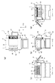
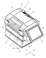
図1(a)〜(d)は本実施の形態に係るインクジェットプリンターを示す平面図、正面図、左側面図および右側面図である。図2はインクジェットプリンターを左斜め前方から見た場合の外観斜視図であり、図3はインクジェットプリンターを右斜め前方から見た場合の外観斜視図である。インクジェットプリンター1は、例えば、図3に示すラベル用紙2に印刷を行う。図示のラベル用紙2は、紙幅方向の両側の縁部分に長さ方向に沿ってスプロケットホール2aが一定の間隔で形成されている台紙2bと、この表面に一定間隔で剥離可能な状態で貼り付けられている矩形のラベル2cを備えている。台紙2bにはラベル2cの間の部位に紙幅方向に延びるミシン目2dが形成されており、各ミシン目2dの位置で折り畳み可能となっている。
1A to 1D are a plan view, a front view, a left side view, and a right side view showing an ink jet printer according to the present embodiment. FIG. 2 is an external perspective view when the ink jet printer is viewed from the left oblique front, and FIG. 3 is an external perspective view when the ink jet printer is viewed from the right oblique front. For example, the inkjet printer 1 performs printing on the
インクジェットプリンター1はプリンター本体部3と、表示・入力操作用のLCDパネル4とを備えている。プリンター本体部3は、第1方向、本例ではプリンター前後方向Yに長い直方体形状の外装ケース5によってプリンター機構部(図示せず)が覆われた構成となっている。外装ケース5によって、プリンター本体部3における第1方向の両側に位置する第1側面および第2側面、本例ではプリンター前後方向Yにおいて対向した位置にある前面6および後側の背面7と、第1方向に直交する第2方向の両側に位置する第3側面および第4側面、本例ではプリンター幅方向Xにおいて対向した位置にある左側面8および右側面9とが規定されている。
The ink jet printer 1 includes a printer
LCDパネル4は第1方向の一方の側の位置、本例では、プリンター本体部3の前面6の上側の部位に、その表示画面4aが第1方向の一方の側、すなわち、前方を向く状態に取り付けられている。本例では、LCDパネル4の裏面上端の両側の部位から裏面側に左右の腕部4b、4cが突出しており、これらの腕部4b、4cの端部が、プリンター幅方向Xに延びる回動中心線回りに回動可能な状態でプリンター本体部3に支持されている。例えば、LCDパネル4は、その表示画面4aがプリンター前方を向く垂直な姿勢の位置から、プリンター上方を向く水平な姿勢の位置までの間を回動可能となっている。
The LCD panel 4 is positioned on one side in the first direction, in this example, on the upper part of the
プリンター本体部3における第2方向の一方の側、本例ではプリンター本体部3の右側面9の下端部からは、プリンター後方に向けて用紙トレイ11が水平に延びている。この用紙トレイ11にラベル用紙2が一定の長さで折り畳まれた積層状態で装着される。右側面9における上側の部位には用紙挿入口12が形成されており、プリンター本体部3には、トラクターユニット13が用紙挿入口12からプリンター右方に突出する状態に取り付けられている。用紙トレイ11に装着されたラベル用紙2は、トラクターユニット13によって、プリンター右側から用紙挿入口12に送り込まれる。
From one side of the printer
プリンター本体部3における第2方向の他方側、本例では右側面9とは反対側の左側面8には、用紙挿入口12と略同一の高さ位置の部位に、用紙排出口14が形成されている。プリンター本体部3には、排出トレイ15が用紙排出口14からプリンター左方に水平に延びる状態で取り付けられている。用紙排出口14からは印刷後のラベル用紙2が排出され、排出トレイ15によってプリンター左方に向けて水平方向に排出される。
On the other side in the second direction of the printer
プリンター本体部3の左側面8において、排出トレイ15のプリンター前側の部位には、インクカートリッジ(図示せず)をプリンター本体部3の内部に形成されているインクカートリッジ装着部(図示せず)に装着するカートリッジ装着口16が形成されており、このカートリッジ装着口16が開閉蓋17によって封鎖されている。この開閉蓋17の下側の部位には、記憶媒体、例えば、印刷情報などが記憶されたメモリカードの挿入口18が形成されている。
In the
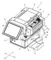
図4はインクジェットプリンター1における外装ケース5の上側部分を取り外した状態を左前方から見た場合の斜視図であり、図5は同一状態のインクジェットプリンター1を右前方から見た場合の斜視図である。また、図6はインクジェットプリンター1の用紙搬送路の部分を示す模式図である。図6において太線で示すように、プリンター本体部3の内部には、プリンター幅方向Xに延びる用紙搬送路21が形成されている。用紙搬送路21は右側面9に形成した用紙挿入口12から左側面8に形成した用紙排出口14まで延びている。
4 is a perspective view when the upper portion of the
用紙搬送路21の下面は、用紙挿入口12からプリンター左方に向けてプリンター幅方向Xの中程の部位まで延びている上流側用紙ガイド22と、これに連続して延びているプラテン23と、これに連続している排出トレイ15によって規定されている。プラテン23は、用紙搬送方向に直交する方向、すなわち、プリンター前後方向Yに沿って所定の間隔で配列されている分割プラテンから構成されている。
The lower surface of the
プラテン23の上方には、プリンター前後方向Yに水平に延びるキャリッジガイド軸24が配置されている。キャリッジガイド軸24は、プリンター本体部3の機構フレーム3aによって支持されている。キャリッジガイド軸24にはスライド可能な状態でヘッドキャリッジ25が取り付けられており、ヘッドキャリッジ25には、印刷位置を規定するプラテン23に対峙するようにノズル面が下向きの姿勢でインクジェットヘッド26が搭載されている(図6参照)。ヘッドキャリッジ25は、モーター25b、ベルト・プーリー機構25cなどから構成される公知のキャリッジ駆動機構25aによって、キャリッジガイド軸24に沿ってプリンター前後方向Yに往復移動可能である。
Above the
ここで、ヘッドキャリッジ25は、図4、5に示すプリンター前側の端がホームポジションであり、印刷待機中においては当該ホームポジションにおいて待機する。このホームポジションに位置するヘッドキャリッジ25に搭載されているインクジェットヘッド26の下側には、ヘッドメンテナンス機構27が搭載されている。ヘッドメンテナンス機構27には、インクジェットヘッド26のノズル面をキャッピングするためのノズルキャップ(図示せず)、各ノズルからインクの吸引を行う吸引機構(図示せず)等が搭載されており、公知のヘッドメンテナンス動作を行ってノズル詰まりの防止、ノズル詰まりを解消するためのメンテナンス動作を行う。ヘッドメンテナンス機構27の下側にはインクカートリッジ装着部28が形成されている。
Here, the
プリンター本体部3の内部には、インクジェットヘッド26の印刷位置とトラクターユニット13の間に、ラベル用紙2を印刷位置に向けて送り込むための紙送りローラー対31が配置されている。紙送りローラー対31は、図6において破線で示すように、紙送りモーター32からの駆動力が、歯車列からなる駆動力伝達機構33を介して伝達される。プラテン23によって規定される印刷位置に対してプリンター左側の部位(用紙搬送方向の下流側の部位)には、印刷が施されたラベル用紙2を排出するための排紙ローラー対34が配置されている。排紙ローラー対34には、図6において破線で示すように、排紙モーター35からの駆動力が、歯車列からなる駆動力伝達機構36を介して伝達される。
A pair of
次に、トラクターユニット13は、長円形の循環経路に沿って循環するトラクターピン42をラベル用紙2の幅方向の両側縁(すなわち、第1方向の一方の側および他方の側)に形成されているスプロケットホール2a(図3参照)に順次に係合させて移動させることで、ラベル用紙2を印刷位置に向けて送り出す。トラクターユニット13には、トラクター駆動モーター43からの駆動力が歯車列からなる駆動力伝達機構44を介して伝達される。
Next, the
このように構成したインクジェットプリンター1において、ラベル用紙2をトラクターユニット13にセットした状態で、LCDパネル4を介して印刷データの選択および印刷指令の入力を行うと、トラクターユニット13が駆動され、ラベル用紙2が用紙搬送路21に沿って印刷位置に向けて送り込まれる。また、紙送りローラー対31および排紙ローラー対34が駆動され、ラベル用紙2は、これらのローラー対31、34によってニップされた状態になる。ラベル用紙2上の印刷開始位置が印刷位置に位置決めされた状態になると、キャリッジ駆動機構25aによってヘッドキャリッジ25が移動してインクジェットヘッド26からインクを吐出するインク吐出動作と、トラクターユニット13、紙送りローラー対31および排紙ローラー対34を駆動してラベル用紙2をプリンター左側(搬送方向の下流側)に向かって送り出す用紙搬送動作とを交互に繰り返して、印刷位置を通過するラベル用紙2上のラベルに印刷を施す。
In the inkjet printer 1 configured as described above, when print data is selected and a print command is input via the LCD panel 4 with the
以上説明したように、本実施の形態に係るインクジェットプリンター1においては、プリンター本体部3の前面6にLCDパネル4が前向きに取り付けられている。また、プリンター本体部3の右側面9には、トラクターユニット13からラベル用紙2が送り込まれる用紙挿入口12が形成され、プリンター本体部3の左側面8にはラベル用紙2が排出される用紙排出口14が形成されている。
As described above, in the ink jet printer 1 according to the present embodiment, the LCD panel 4 is attached to the
したがって、LCDパネル4を目視しながら操作を行うために、インクジェトプリンター1の前面6の前方に位置する操作者は、インクジェットプリンター1の右側の用紙挿入口12および左側の用紙排出口14のいずれに対しても、容易にアクセスすることができ、体を大きく傾けるなどの動作を行うことなく、用紙挿入口12および用紙排出口14を目視できる。よって、LCDパネル4の視認性、操作性を維持しつつ、用紙挿入口12の側におけるラベル用紙2のセット作業、用紙排出口14の側における印刷後のラベル用紙2の排出作業などを効率良く簡単に行うことができる。
Therefore, in order to perform the operation while viewing the LCD panel 4, an operator positioned in front of the
また、インクジェットヘッド26は第1方向であるプリンター前後方向Xに往復移動するように搭載され、本例では第1方向の一方の側であるプリンター前側の端がホームポジションとされ、この部位にヘッドメンテナンス機構27が配置されている。(なお、第1方向の他方側、本例ではプリンター後側の端をホームポジションとすることもできる。)このホームポジションおよびヘッドメンテナンス機構27の両側(プリンター幅方向の両側)にはスペースができる。プリンター本体部3の右側面9にはトラクターユニット13が配置されているので、本例では、プリンター本体部3の左側のスペースにインクカートリッジ装着部28を配置し、これに対峙している左側面8におけるプリンター前側の部位に形成したカートリッジ装着口16を介してプリンター左方からインクカートリッジの装着、交換作業を行うことができる。したがって、プリンター本体部3をコンパクトに構成できると共に、インクカートリッジの装着、交換作業も、プリンター前側において、側方に位置するカートリッジ装着口16を介して簡単に行うことができる。
The
なお、上記のインクジェットプリンター1では、プリンター前面にLCDパネル4を配置し、プリンターの左右の側面に用紙挿入口および用紙排出口を配置してある。例えば、プリンターの左右の側面の一方に、側方を向く状態にLDCパネルを配置し、プリンターの前後に用紙挿入口および用紙排出口を配置した構成とすることも可能である。この場合には、操作者は、LCDパネルが取り付けられているプリンター側方に立つことで、LCDパネルの操作性、視認性を損なうことなく、プリンター前後の用紙挿入口および用紙排出口の双方に対して容易にアクセスできるので、ラベル用紙のセット作業、排出作業などを効率良く簡単に行うことができる。 In the ink jet printer 1 described above, the LCD panel 4 is disposed on the front surface of the printer, and a paper insertion port and a paper discharge port are disposed on the left and right side surfaces of the printer. For example, an LDC panel may be disposed on one of the left and right side surfaces of the printer so as to face sideways, and a sheet insertion port and a sheet discharge port may be disposed on the front and rear sides of the printer. In this case, the operator stands on the side of the printer to which the LCD panel is attached, so that the operator can view both the paper insertion opening and the paper discharge opening before and after the printer without impairing the operability and visibility of the LCD panel. Since it can be easily accessed, it is possible to efficiently and easily perform label paper setting work and discharging work.
また、上記のラベル印刷システムSのラベルプリンター1は、所謂、スタンドアローンで使用可能なものであるが、上位のホストコンピューター等から印刷指令、印刷データを受信して印刷動作を行う構成のラベルプリンターに対しても本発明を同様に適用可能なことは勿論である。 The label printer 1 of the above-described label printing system S can be used as a so-called stand-alone, but is configured to receive a print command and print data from a host computer or the like on the upper side and perform a printing operation. Of course, the present invention is applicable to the above.
さらに、印刷ヘッドとして、インクジェットヘッドの代わりに、サーマルヘッドなどのインクジェットヘッドとは異なる種類の印刷ヘッドが搭載されたプリンターに対しても本発明を適用することができる。 Furthermore, the present invention can also be applied to a printer having a print head of a type different from an ink jet head such as a thermal head instead of the ink jet head as a print head.
さらには、印刷対象の記録媒体としては上記のようにスプロケットホールが形成されているラベル用紙以外の連続用紙、例えば、ロール紙を用いることもできる。この場合には、上記のインクジェットプリンター1において、用紙排出口14が形成されている左側面8に、ロール紙装着口を形成しておけばよい。この場合には、プリンター前方の側から、側方に位置するロール紙装着口を介してロール紙の装着、交換作業を簡単に行うことができる。
Furthermore, as the recording medium to be printed, continuous paper other than the label paper on which the sprocket holes are formed as described above, for example, roll paper can be used. In this case, in the ink jet printer 1 described above, a roll paper mounting opening may be formed on the
また、排出口から排出された記録媒体を巻き取るロール紙装着ユニットを設けることもできる。この場合には、ロール紙装着ユニットをプリンターにおける排出口が位置する第2方向の他方の側(上記の例では、左側面8)に設けておくことが望ましい。
In addition, a roll paper mounting unit for winding the recording medium discharged from the discharge port can be provided. In this case, it is desirable to provide the roll paper mounting unit on the other side in the second direction where the discharge port of the printer is located (the
1・・インクジェットプリンター、2・・ラベル用紙、2a・・スプロケットホール、2b・・台紙、2c・・ラベル、2d・・ミシン目、3・・プリンター本体部、3a・・機構フレーム、4・・LCDパネル、4a・・表示画面、4b,4c・・腕部、5・・外装ケース、6・・前面、7・・背面、8・・左側面、9・・右側面、11・・用紙トレイ、12・・用紙挿入口、13・・トラクターユニット、14・・用紙排出口、15・・排出トレイ、16・・カートリッジ装着口、17・・開閉蓋、18・・挿入口、21・・用紙搬送路、22・・上流側用紙ガイド、23・・プラテン、24・・キャリッジガイド軸、25・・ヘッドキャリッジ、25a・・キャリッジ駆動機構、25b・・モーター、25c・・ベルト・プーリー機構、26・・インクジェットヘッド、27・・ヘッドメンテナンス機構、28・・インクカートリッジ装着部、31・・紙送りローラー対、32・・紙送りモーター、33・・駆動力伝達機構、34・・排紙ローラー対、35・・排紙モーター、36・・駆動力伝達機構、42・・トラクターピン、43・・トラクター駆動モーター、44・・駆動力伝達機構
1. ・ Inkjet printer, 2. ・ Label paper, 2a ・ ・ Sprocket hole, 2b ・ ・ Mount, 2c ・ ・ Label, 2d ・ ・ Perforation, 3 ・ ・ Printer body, 3a ・ ・ Mechanical frame, 4 ・ ・LCD panel, 4a ... display screen, 4b, 4c ... arm, 5 ... exterior case, 6 ... front, 7 ... back, 8 ... left side, 9 ... right side, 11 ... paper tray , 12 .. Paper insertion opening, 13 .. Tractor unit, 14 .. Paper discharge opening, 15 .. Ejection tray, 16 .. Cartridge installation opening, 17 .. Opening / closing lid, 18. Conveyance path, 22 .... upstream side paper guide, 23 .... platen, 24 .... carriage guide shaft, 25 .... head carriage, 25a..carriage drive mechanism, 25b..motor, 25c..
Claims (5)
前記プリンター本体部の前記第1方向の一方の側に取り付けられ、表示画面が前記第1の方向の一方の側に向いて操作入力されるパネルと、
前記プリンター本体部の前記第1方向と直交する第2方向の一方の側に配設されて前記ラベル用紙を前記プリンター本体部に挿入する挿入口と、
前記プリンター本体部の前記第2方向の他方の側に配設されて前記ラベル用紙を前記プリンター本体部から排出する排出口と、
前記第2の方向の前記一方の側に配設される前記挿入口から前記第2の方向の前記他方の側に配設される前記排出口に延びる用紙搬送路と、
を備えることを特徴とするプリンター。 A printer main body having a print head that moves in a first direction and performs printing on a label paper having labels attached to the surface of the mount at predetermined intervals ;
A panel that is attached to one side of the first direction of the printer main body and that is operated and input with a display screen directed to one side of the first direction ;
An insertion port disposed on one side of a second direction orthogonal to the first direction of the printer main body, and for inserting the label paper into the printer main body;
A discharge port disposed on the other side of the printer main body in the second direction and discharging the label paper from the printer main body;
A paper conveyance path extending from the insertion port disposed on the one side in the second direction to the discharge port disposed on the other side in the second direction;
A printer comprising:
前記インクジェットヘッドは、印刷待機中、前記プリンター本体部の前記第1方向の一方の側で停止する請求項1に記載のプリンター。 The print head is an inkjet head that ejects ink;
The printer according to claim 1, wherein the inkjet head stops on one side in the first direction of the printer main body during printing standby.
前記トラクターピンを移動させて前記ラベル用紙を前記挿入口に向けて搬送するトラクターユニットを前記第2方向の一方の側に備える請求項1乃至3のいずれか1項に記載のプリンター。 A tractor pin that engages with a sprocket hole formed on one side and the other side of the label sheet in the first direction;
The printer according to claim 1, further comprising a tractor unit that moves the tractor pin and conveys the label sheet toward the insertion port on one side in the second direction.
Priority Applications (2)
| Application Number | Priority Date | Filing Date | Title |
|---|---|---|---|
| JP2012122799A JP5962217B2 (en) | 2012-05-30 | 2012-05-30 | printer |
| CN2013203049576U CN203317886U (en) | 2012-05-30 | 2013-05-30 | Printer |
Applications Claiming Priority (1)
| Application Number | Priority Date | Filing Date | Title |
|---|---|---|---|
| JP2012122799A JP5962217B2 (en) | 2012-05-30 | 2012-05-30 | printer |
Publications (3)
| Publication Number | Publication Date |
|---|---|
| JP2013248739A JP2013248739A (en) | 2013-12-12 |
| JP2013248739A5 JP2013248739A5 (en) | 2015-05-28 |
| JP5962217B2 true JP5962217B2 (en) | 2016-08-03 |
Family
ID=49657271
Family Applications (1)
| Application Number | Title | Priority Date | Filing Date |
|---|---|---|---|
| JP2012122799A Expired - Fee Related JP5962217B2 (en) | 2012-05-30 | 2012-05-30 | printer |
Country Status (2)
| Country | Link |
|---|---|
| JP (1) | JP5962217B2 (en) |
| CN (1) | CN203317886U (en) |
Families Citing this family (1)
| Publication number | Priority date | Publication date | Assignee | Title |
|---|---|---|---|---|
| JP6544509B2 (en) * | 2015-03-06 | 2019-07-17 | セイコーエプソン株式会社 | Recording device |
Family Cites Families (5)
| Publication number | Priority date | Publication date | Assignee | Title |
|---|---|---|---|---|
| JPH10244704A (en) * | 1997-03-04 | 1998-09-14 | Ricoh Co Ltd | Recording apparatus |
| JP2000039750A (en) * | 1998-07-21 | 2000-02-08 | Copyer Co Ltd | Image forming device |
| JP2006168072A (en) * | 2004-12-14 | 2006-06-29 | Canon Inc | Delivery-recovering process method, and inkjet-recording apparatus which can use it |
| JP2009292128A (en) * | 2008-06-09 | 2009-12-17 | Seiko Epson Corp | Recorder, and recording method in recorder |
| JP2012056224A (en) * | 2010-09-10 | 2012-03-22 | Seiko Epson Corp | Paper conveyance device and printer |
-
2012
- 2012-05-30 JP JP2012122799A patent/JP5962217B2/en not_active Expired - Fee Related
-
2013
- 2013-05-30 CN CN2013203049576U patent/CN203317886U/en not_active Expired - Fee Related
Also Published As
| Publication number | Publication date |
|---|---|
| CN203317886U (en) | 2013-12-04 |
| JP2013248739A (en) | 2013-12-12 |
Similar Documents
| Publication | Publication Date | Title |
|---|---|---|
| US8282206B2 (en) | Printer | |
| US9227437B2 (en) | Label printer and label printing system | |
| EP2065207B1 (en) | Recording device having a conveying unit that conveys a recording medium | |
| TWI499512B (en) | Apparatus comprising recording device and tractor, tractor unit, and recording device | |
| JP5962217B2 (en) | printer | |
| US7819520B2 (en) | Printer | |
| JP6051933B2 (en) | Printer and printer control method | |
| JP4941441B2 (en) | Ink jet recording apparatus and borderless recording method | |
| JP6069912B2 (en) | Recording device | |
| CN113199861B (en) | Printing device | |
| JP5316443B2 (en) | Inkjet printer | |
| US7905486B2 (en) | Transportation apparatus for transporting transportation target medium, recording apparatus having the same, and control method for controlling the same | |
| JP6314436B2 (en) | Printing device | |
| JP2010076878A (en) | Image forming device | |
| US20130182058A1 (en) | Tractor, tractor unit, and recording device | |
| JP2855001B2 (en) | Recording device and information processing device | |
| US20240092099A1 (en) | Printing apparatus | |
| JP2005224960A (en) | Inkjet recording apparatus | |
| JP5970707B2 (en) | Recording device | |
| JP2024004665A (en) | printer | |
| JP5915163B2 (en) | Tractor, tractor unit, and recording device | |
| JP3705213B2 (en) | Inkjet printer | |
| JP2023050221A (en) | printer | |
| JP4609150B2 (en) | Printing device | |
| JP4665773B2 (en) | RECORDING DEVICE, RECORDING DEVICE CONTROL METHOD, AND CONTROL PROGRAM |
Legal Events
| Date | Code | Title | Description |
|---|---|---|---|
| RD04 | Notification of resignation of power of attorney |
Free format text: JAPANESE INTERMEDIATE CODE: A7424 Effective date: 20150107 |
|
| A521 | Written amendment |
Free format text: JAPANESE INTERMEDIATE CODE: A523 Effective date: 20150408 |
|
| A621 | Written request for application examination |
Free format text: JAPANESE INTERMEDIATE CODE: A621 Effective date: 20150408 |
|
| A131 | Notification of reasons for refusal |
Free format text: JAPANESE INTERMEDIATE CODE: A131 Effective date: 20151110 |
|
| A521 | Written amendment |
Free format text: JAPANESE INTERMEDIATE CODE: A523 Effective date: 20151228 |
|
| TRDD | Decision of grant or rejection written | ||
| A01 | Written decision to grant a patent or to grant a registration (utility model) |
Free format text: JAPANESE INTERMEDIATE CODE: A01 Effective date: 20160531 |
|
| A61 | First payment of annual fees (during grant procedure) |
Free format text: JAPANESE INTERMEDIATE CODE: A61 Effective date: 20160613 |
|
| R150 | Certificate of patent or registration of utility model |
Ref document number: 5962217 Country of ref document: JP Free format text: JAPANESE INTERMEDIATE CODE: R150 |
|
| LAPS | Cancellation because of no payment of annual fees |