JP5960558B2 - Wireless router device - Google Patents
Wireless router device Download PDFInfo
- Publication number
- JP5960558B2 JP5960558B2 JP2012196174A JP2012196174A JP5960558B2 JP 5960558 B2 JP5960558 B2 JP 5960558B2 JP 2012196174 A JP2012196174 A JP 2012196174A JP 2012196174 A JP2012196174 A JP 2012196174A JP 5960558 B2 JP5960558 B2 JP 5960558B2
- Authority
- JP
- Japan
- Prior art keywords
- unit
- wireless router
- router device
- power supply
- supply circuit
- Prior art date
- Legal status (The legal status is an assumption and is not a legal conclusion. Google has not performed a legal analysis and makes no representation as to the accuracy of the status listed.)
- Active
Links
Images


Classifications
-
- Y—GENERAL TAGGING OF NEW TECHNOLOGICAL DEVELOPMENTS; GENERAL TAGGING OF CROSS-SECTIONAL TECHNOLOGIES SPANNING OVER SEVERAL SECTIONS OF THE IPC; TECHNICAL SUBJECTS COVERED BY FORMER USPC CROSS-REFERENCE ART COLLECTIONS [XRACs] AND DIGESTS
- Y02—TECHNOLOGIES OR APPLICATIONS FOR MITIGATION OR ADAPTATION AGAINST CLIMATE CHANGE
- Y02D—CLIMATE CHANGE MITIGATION TECHNOLOGIES IN INFORMATION AND COMMUNICATION TECHNOLOGIES [ICT], I.E. INFORMATION AND COMMUNICATION TECHNOLOGIES AIMING AT THE REDUCTION OF THEIR OWN ENERGY USE
- Y02D30/00—Reducing energy consumption in communication networks
- Y02D30/70—Reducing energy consumption in communication networks in wireless communication networks
Description
本発明は、無線ルータ装置に関し、例えば、ブルートゥース(Bluetooth:登録商標)通信機能を有する移動通信端末と通信する無線ルータ装置に関する。 The present invention relates to a wireless router device, for example, a wireless router device that communicates with a mobile communication terminal having a Bluetooth (registered trademark) communication function.
近年、スマートフォンや、携帯電話機や、携帯ゲーム機などの移動通信端末(モバイル機器)を無線ルータ装置に接続することにより、WiMAX(登録商標)(Worldwide Interoperability for Microwave Access)や、LTE(Long Term Evolution)、3Gなどの無線WAN(Wide Area Network)回線を通じてインターネットに接続できることが、広く知られている。すなわち、無線ルータ装置は、WiMAXや、LTE、3Gなどの公衆回線と接続し、ルーティング動作を行うことによって、移動通信端末をインターネットに接続させることができる。また、一般的な無線ルータ装置は、ブルートゥース(Bluetooth:登録商標)通信機能を有しており、ブルートゥース通信機能を有する移動通信端末との間で、無線通信を行うこともできる。 In recent years, by connecting mobile communication terminals (mobile devices) such as smartphones, mobile phones, and portable game machines to wireless router devices, WiMAX (registered trademark) (Worldwide Interoperability for Microwave Access) and LTE (Long Term Evolution) It is widely known that it can be connected to the Internet through a wireless WAN (Wide Area Network) line such as 3G. That is, the wireless router device can connect a mobile communication terminal to the Internet by connecting to a public line such as WiMAX, LTE, or 3G and performing a routing operation. In addition, a general wireless router device has a Bluetooth (registered trademark) communication function, and can perform wireless communication with a mobile communication terminal having a Bluetooth communication function.
ここで、無線ルータ装置は、移動通信端末がインターネットに接続していない時間が一定時間経過した場合などに、バッテリ電源の消費電力を抑えるために、自動的にシャットダウンまたはスタンバイモードに移行するものが、知られている。 Here, there are wireless router devices that automatically enter the shutdown or standby mode in order to reduce the power consumption of the battery power source when the mobile communication terminal is not connected to the Internet for a certain period of time. ,Are known.
なお、本発明に関連する技術が、特許文献1に開示されている。 A technique related to the present invention is disclosed in Patent Document 1.
しかしながら、無線ルータ装置が一旦、スタンバイモード等に入った後、もう一度、無線ルータ装置を起動させようとする場合、無線ルータ装置の電源ボタンを再度押す作業が必要となる。このため、無線ルータ装置の起動に手間がかかるという問題があった。 However, when the wireless router device once enters the standby mode or the like and wants to activate the wireless router device again, it is necessary to press the power button of the wireless router device again. For this reason, there is a problem that it takes time to start the wireless router device.
無線ルータ装置は、近年、持ち運びが可能となり、無線通信さえ可能であれば、ルータ機能を発揮できることから、カバンなど手の届きにくいところに、配置されることも多い。この場合、無線ルータ装置の利用者は、無線ルータ装置を起動しようとする度に、電源ボタンを押すために、当該無線ルータ装置をカバンから取り出す必要が生じてしまう。 In recent years, a wireless router device can be carried, and as long as wireless communication is possible, the router function can be exhibited. Therefore, the wireless router device is often arranged in a place where it is difficult to reach such as a bag. In this case, every time the user of the wireless router device tries to activate the wireless router device, the user needs to take out the wireless router device from the bag in order to press the power button.
また、無線ルータ装置と移動通信端末と間のデータ通信で用いられる無線LANの接続開始をトリガとして、無線ルータ装置を起動させることも考えられる。しかしながら、無線LANは待機中であっても消費電力が大きいため、スタンバイモード時の待ち受け時間が短縮してしまう問題があった。 It is also conceivable to start up the wireless router device triggered by the start of connection of a wireless LAN used in data communication between the wireless router device and the mobile communication terminal. However, since the wireless LAN consumes a large amount of power even in standby, there is a problem that standby time in the standby mode is shortened.
そこで、無線LANと比較して消費電力が小さいブルートゥース通信を用いて、無線ルータ装置を起動することが考えられる。通常、ブルートゥース通信を実現するには、双方の移動通信端末をペアリングする必要がある。一方で、多くの移動通信端末は、ペアリング登録されている移動通信端末同士が通信可能範囲内に入ると、自動的に接続を開始してしまう。このため、移動通信端末がペアリングされると、任意のタイミングで移動通信端末間の接続を開始することが困難となるため、無線ルータ装置を起動させるトリガには適さない。 Thus, it is conceivable to activate the wireless router device using Bluetooth communication, which consumes less power than the wireless LAN. Usually, in order to realize Bluetooth communication, it is necessary to pair both mobile communication terminals. On the other hand, many mobile communication terminals automatically start connection when paired registered mobile communication terminals are within the communicable range. For this reason, when the mobile communication terminals are paired, it becomes difficult to start connection between the mobile communication terminals at an arbitrary timing, and therefore, it is not suitable as a trigger for starting the wireless router device.
また、移動通信端末同士をペアリングしない状態にしておき、無線ルータ装置をペアリング登録待ち時に使用されるディスカバラブルモードに無線ルータ装置を設定することもできる。この場合、移動通信端末側からは任意のタイミングで接続を開始することができるため、ディスカバラブルモードに無線ルータ装置を設定することを無線ルータ装置の起動トリガとして用いることができる。 It is also possible to set the wireless router device to a discoverable mode that is used when waiting for pairing registration while the mobile communication terminals are not paired. In this case, since the connection can be started at an arbitrary timing from the mobile communication terminal side, setting the wireless router device in the discoverable mode can be used as an activation trigger for the wireless router device.
しかしながら、ディスカバラブルモードでは、通信可能範囲内に存在するブルートゥース機器の全てが無線ルータ装置に接続できてしまうという問題が生じる。 However, in the discoverable mode, there arises a problem that all of the Bluetooth devices existing within the communicable range can be connected to the wireless router device.
本発明は、このような事情に鑑みてなされたものであり、本発明の目的は、他のブルートゥース機能を有する機器とペアリングすることなく、ブルートゥースの接続開始を起動トリガとして、簡単に起動することができる無線ルータ装置を提供することにある。 The present invention has been made in view of such circumstances, and an object of the present invention is to simply start using a Bluetooth connection start as an activation trigger without pairing with another device having a Bluetooth function. It is an object of the present invention to provide a wireless router device that can be used.
本発明の無線ルータ装置は、ブルートゥース通信機能を有する移動通信端末と通信する無線ルータ装置であって、前記移動通信端末とブルートゥース通信を行うブルートゥース通信部と、前記移動通信端末と無線LANにより通信する無線LAN通信部と、前記ブルートゥース通信部および前記無線LAN通信部のデータ通信を制御するメイン制御部と、前記ブルートゥース通信部、前記無線LAN通信部および前記メイン制御部への電源を供給する電源回路部と、前記電源回路部が、前記無線LAN通信部および前記メイン制御部に対して電源供給を行い、前記ブルートゥース通信部に電源供給を行わないモードである通信モードと、前記電源回路部が、前記ブルートゥース通信部に電源供給を行い、前記無線LAN通信部および前記メイン制御部に対して電源供給を行わないモードであるスタンバイモードとを切り替えて、前記電源回路部の電源供給を制御する電源回路制御部と、前記電源回路制御部が前記スタンバイモードで前記電源回路部を制御している場合に、当該無線ルータ装置の周囲の前記移動通信端末が前記無線ルータ装置に対して接続の要求を行う接続要求があるか否かを判断する接続要求判断部と、前記接続要求判断部により前記接続要求があると判断された場合、前記接続要求内に当該無線ルータ装置の識別情報が含まれているか否かを判断する識別情報存否判断部とを備え、前記識別情報存否判断部が前記接続要求内に当該無線ルータ装置の識別情報が含まれていると判断した場合、前記ブルートゥース通信部は、前記電源回路制御部に対して、前記通信モードで前記電源回路部を制御させるための起動トリガを入力し、前記電源回路制御部は、前記起動トリガに従って、前記通信モードで前記電源回路部を制御する。 The wireless router device of the present invention is a wireless router device that communicates with a mobile communication terminal having a Bluetooth communication function, and communicates with the mobile communication terminal via a wireless LAN and a Bluetooth communication unit that performs Bluetooth communication with the mobile communication terminal. A wireless LAN communication unit, a main control unit that controls data communication of the Bluetooth communication unit and the wireless LAN communication unit, and a power supply circuit that supplies power to the Bluetooth communication unit, the wireless LAN communication unit, and the main control unit And a communication mode in which the power supply circuit unit supplies power to the wireless LAN communication unit and the main control unit and does not supply power to the Bluetooth communication unit, and the power supply circuit unit includes: Supplying power to the Bluetooth communication unit, the wireless LAN communication unit and the memory A power supply circuit control unit that controls a power supply of the power supply circuit unit by switching a standby mode that is a mode in which power supply to the control unit is not performed; and A connection request determination unit that determines whether or not there is a connection request for the mobile communication terminal around the wireless router device to make a connection request to the wireless router device, and the connection An identification information presence / absence determination unit that determines whether or not the connection request includes identification information of the wireless router device when the request determination unit determines that the connection request is present; When the determination unit determines that the identification information of the wireless router device is included in the connection request, the Bluetooth communication unit transmits the communication to the power supply circuit control unit. Enter an activation trigger for causing control the power supply circuit portion is over-de, the power supply circuit control unit in accordance with the activation trigger, controls the power supply circuit unit in the communication mode.
本発明にかかる無線ルータ装置によれば、他のブルートゥース通信機能を有する機器とペアリングすることなく、ブルートゥースの接続開始を起動トリガとして、簡単に起動することができる。 According to the wireless router device of the present invention, it is possible to easily start up using the Bluetooth connection start as an activation trigger without pairing with another device having the Bluetooth communication function.
<第1の実施の形態>
本発明の第1の実施の形態における無線ルータ装置100について、図に基づいて説明する。
<First Embodiment>
A
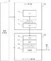
図1は、本発明の第1の実施の形態における無線ルータ装置100の構成を示す。無線ルータ装置100は、少なくともブルートゥース通信機能を有する移動通信端末200と通信する。移動通信端末200の構成については、図3を用いて、後で詳しく説明する。
FIG. 1 shows a configuration of a
図1に示されるように、無線ルータ装置100は、公衆網接続用通信部110と、公衆網接続用通信部用アンテナ部111と、無線LAN通信部120と、無線LAN通信部用アンテナ部121と、ブルートゥース通信部130と、ブルートゥース通信部用アンテナ部131と、バッテリ部140と、電源回路部150と、記憶部160と、メイン制御部170と、サブ制御部180と、スイッチ部190を含んで構成されている。
As shown in FIG. 1, the
また、後述するように、無線ルータ装置100は、通信モードと、スタンバイモードの2つのモードで切り替え動作する。スタンバイモードは、ブルートゥース通信部130のみが電源供給を受け動作するモードで、通信モードと比較すると制限された動作モードである。通信モードおよびスタンバイモードの定義および詳しい説明は後述する。
Further, as will be described later, the
なお、ここでは、無線ルータ装置100は、移動式無線ルータ装置を想定する。この移動式無線ルータ装置は、モバイルルータ装置とも呼ばれる。この移動式無線ルータ装置は、バッテリにより電源供給を受けて動作することができ、可搬性が高い。このため、移動式無線ルータ装置は、据え置き式の無線ルータ装置と比較して、WAN回線や電源がワイヤレスになるため、持ち運んで様々なシーンで使用できる。
Here, the
以下、無線ルータ装置100の各構成について、具体的に説明する。
Hereinafter, each configuration of the
公衆網接続用通信部110は、通信接続された移動通信端末200を公衆網へ接続する。公衆網接続用通信部110は、例えばWiMAXなどの無線WAN回線(公衆網)に接続し、ルーティング動作を行うことによって、移動通信端末200をインターネット接続させることができる。なお、公衆接続用通信部110は、携帯電話機の3G、LTEに対応するモジュールや、PHSのモジュールであってもよい。
The public network connection communication unit 110 connects the
公衆網接続用通信部用アンテナ部111は、公衆網接続用通信部110に接続され、公衆網への接続に対応する信号を送受する。
The public network connection communication
無線LAN通信部120は、移動通信端末200と無線LANにより通信する。
The wireless
無線LAN通信部用アンテナ部121は、無線LAN通信部120に接続され、無線LAN通信に対応する信号を送受する。
The wireless LAN communication
ブルートゥース通信部130は、移動通信端末200とブルートゥース通信行う。
The Bluetooth
ブルートゥース通信部用アンテナ部131は、ブルートゥース通信部130に接続され、ブルートゥース通信に対応する信号を送受する。
The Bluetooth communication
ブルートゥース通信部130は、さらに、接続要求判断部132と、識別情報存否判断部133と、起動トリガ発生部134とを備えている。
The Bluetooth
接続要求判断部132は、後述の電源回路制御部181が後述のスタンバイモードで電源回路部150を制御している場合に、当該無線ルータ装置100の周囲の移動通信端末200が無線ルータ装置100に対して接続の要求を行う接続要求があるか否かを判断する。
The connection
識別情報存否判断部133は、接続要求判断部132により接続要求があると判断された場合、接続要求内に当該無線ルータ装置100の識別情報が含まれているか否かを判断する。
When the connection
ここで、無線ルータ装置100は、固有の識別情報を有している。ここでは、この識別情報は、ブルートゥースデバイスアドレス(以下、BDアドレスと称する場合がある)とする。移動通信端末200は、このBDアドレスを用いて無線ルータ装置100へ接続することによって、接続先の無線ルータ装置100を識別したうえで通信接続することができる。
Here, the
起動トリガ発生部134は、動作トリガを発生する。ここで、動作トリガとは、通信モードで電源回路部150を制御させるための信号である。通信モードの定義は、後述する。
The
バッテリ部140は、例えばリチウムイオン充電地やニッケル水素充電地などの二次電池である。
The
電源回路部150は、公衆網接続用通信部110、無線LAN通信部120、ブルートゥース通信部130およびメイン制御部170に電源を供給する。より具体的には、電源回路部150は、バッテリ部140の電源を、公衆網接続用通信部110、無線LAN通信部120、ブルートゥース通信部130およびメイン制御部170に供給する。
The power
記憶部160は、無線ルータ装置100に入力された各種データを記憶する。記憶部160は、Flash Memoryなどにより構成される。
The storage unit 160 stores various data input to the
メイン制御部170は、無線ルータ装置100の主な制御を司り、ルーティング動作や、
公衆網接続用通信部110、無線LAN通信部120およびブルートゥース通信部130のデータ通信を制御する。メイン制御部170は、中央処理装置(CPU:Central Processing Unit)として機能する。また、メイン制御部170には、OS(Operating System)を起動する機能を有する。
The
Data communication of the public network connection communication unit 110, the wireless
メイン制御部170は、無通信タイムアウト判定部171と、モード移行信号発生部172とを有している。
The
無通信タイムアウト判定部171は、無線ルータ装置100と移動通信端末200との間でデータ通信が行われていない時間が所定の設定時間を超過したか否かを判断する。
The no-communication
モード移行信号発生部172は、モード移行監視部183によりモード移行を指示する信号が含まれる場合に、電源回路制御部181に対してモード移行させる命令信号を発生し、この命令信号を電源回路制御部181へ入力する。
When the mode
サブ制御部180は、電源回路部150を制御する。また、サブ制御部180は、メイン制御部170とは別に独立して動作する。
The
図1に示されるように、サブ制御部180は、電源回路制御部181と、スイッチ監視部182と、モード移行監視部183とを有している。
As shown in FIG. 1, the
電源回路制御部181は、次に説明するように、通信モードと、スタンバイモードとを切り替えて、電源回路部150の電源供給を制御する。なお、通信モードで動作することを、無線ルータ装置100をオンにする(起動する)ともいう場合がある。スタンバイモードで動作することを、無線ルータ装置100をオフにするともいう場合がある。
The power supply
通信モードとは、電源回路部150が、公衆網接続用通信部110、無線LAN通信部120およびメイン制御部170に対して電源供給を行い、ブルートゥース通信部130に電源供給を行わないモードである。このとき、メイン制御部170に電源供給が行われているので、公衆網接続用通信部110およびLAN通信部120は、微小な電力を用いる信号通信とともに、大きな電力を用いるデータ通信を行うことができる。
The communication mode is a mode in which the power
スタンバイモードとは、電源回路部150が、ブルートゥース通信部130に電源供給を行い、公衆網接続用通信部110、無線LAN通信部130およびメイン制御部170に対して電源供給を行わないモードである。このとき、メイン制御部170に電源供給が行われていないので、公衆網接続用通信部110、無線LAN通信部120およびブルートゥース通信部130は、大きな電力を用いるデータ通信を行うことができない。また、公衆網接続用通信部110および無線LAN通信部130にも電源供給が行われていないので、大きな電力を用いるデータ通信ももちろん、微小な電力を用いる信号の通信も行えない。一方、ブルートゥース通信部130に電源供給が行われるので、ブルートゥース通信部130は、微小な電力を用いる信号通信とともに、大きな電力を用いるデータ通信を行うことができる。
The standby mode is a mode in which the power
電源回路制御部181は、後述のスイッチ部190のオンオフによって、通信モードまたはスタンバイモードを切り替えて電源回路部150の電源供給を制御する。さらに、電源回路制御部181は、ブルートゥース通信部130から入力される動作トリガに従って、スタンバイモードから通信モードに切り替えて、電源回路部150の電源供給を制御する。ここでいう動作トリガは、前述の通り、通信モードで電源回路部150を制御させるための信号である。
The power supply
スイッチ監視部182は、後述のスイッチ部190のオンオフを監視する。具体的には、スイッチ監視部182は、スイッチ部190がスタンバイモードに切り替わるようにオフにされているか、あるいはスイッチ部190が通信モードに切り替わるようにオンにされているかを監視する。
The switch monitoring unit 182 monitors on / off of a
モード移行監視部183は、ブルートゥース通信部130により受信されるデータや信号の中に、モード移行を指示する信号が含まれるか否かを監視する。
The mode
なお、サブ制御部180には、例えば、メイン制御部170と比較して非常に消費電力が低いマイコンを用いることができる。これにより、スタンバイモード時の無線ルータ装置100の消費電力を減少させることができる。
As the
スイッチ部190は、電源回路制御部181を、通信モードまたはスタンバイモードに切り替えるためのスイッチである。スイッチ部190をオンにすると、通信モードに切り替わり、スイッチ部190をオフにすると、スタンバイモードに切り替わる。なお、スイッチ部190は、例えば押しボタン方式で構成されている。
The
次に、無線ルータ装置100のメイン制御部170、ブルートゥース通信部130および電源回路部150の関係について、説明する。
Next, the relationship among the
図2は、無線ルータ装置100のメイン制御部170、ブルートゥース通信部130および電源回路部150の関係を示す図である。
FIG. 2 is a diagram illustrating a relationship among the
図2に示されるように、電源回路部150は、メイン制御部170およびブルートゥース通信部130の各々に接続されている。ブルートゥース通信部130は、図1に示した構成とは別に、無線部135と、リンクコントローラ136と、LMP(Link Management Protocol)137と、HCI(Host Controller Interface)138とを有している。
As shown in FIG. 2, the power
無線部135は、移動通信端末200と無線接続するために必要な電波を制御する。
The
リンクコントローラ136は、ブルートゥース通信部130のベースバンドとして機能し、周波数ホッピングや最下層のパケット送受信などを制御する。
The
LMP137は、ブルートゥース通信を確立するためにリンクコントローラ136を制御するプロトコルである。
HCI138は、メイン制御部170(ホスト)とブルートゥース通信部130(コントローラ)との間で通信を行うためのプロトコルである。HCIプロトコルには、例えばUSB(Universal Serial Bus)、SDIO(Secure Digital Input/Output)、UART(Universal Asynchronous Receiver Transmitter)といった物理バスが使われている。 The HCI 138 is a protocol for performing communication between the main control unit 170 (host) and the Bluetooth communication unit 130 (controller). For the HCI protocol, for example, a physical bus such as USB (Universal Serial Bus), SDIO (Secure Digital Input / Output), or UART (Universal Asynchronous Receiver Transmitter) is used.
メイン制御部170は、HCI173と、Bluetoothプロトコルスタック174と、OS175とを有している。
The
HCI173は、前述のHCI138と同様に、メイン制御部170(ホスト)とブルートゥース通信部130(コントローラ)との間で通信を行うためのプロトコルである。
The
Bluetoothプロトコルスタック174は、複数接続を管理するL2CAP(Logical Link Control and Adaptation Protocol)や、シリアル通信をエミュートするRFCOMM(Radio Frequency Communication)などのプロトコルを有する。
The
ただし、Bluetoothプロトコルスタック174は、通常のブルートゥース通信には必要ではあるが、本発明の接続時には使用されない。このBluetoothプロトコルスタック174を使用しなくても、無線ルータ装置100を起動することができる点が本発明の優位点でもある。
However, although the
次に、無線ルータ装置100と通信接続する移動通信端末200の構成を説明する。
Next, the configuration of the
図3は、無線ルータ装置100と通信する移動通信端末200の構成を示す図である。
FIG. 3 is a diagram illustrating a configuration of the
移動通信端末200は、少なくともブルートゥース通信機能を有する端末である。移動通信端末200は、例えばスマートフォンや、携帯電話機や、携帯ゲーム機などであり、モバイル機器とも呼ばれている。
The
図3に示されるように、移動通信端末200は、無線LAN通信部220と、無線LAN通信部用アンテナ部221と、ブルートゥース通信部230と、ブルートゥース通信部用アンテナ部231と、メイン制御部270とを有している。
As illustrated in FIG. 3, the
無線LAN通信部220は、無線ルータ装置100と無線LANにより通信する。
The wireless
無線LAN通信部用アンテナ部221は、無線LAN通信部220に接続され、無線LAN通信に対応する信号を送受する。
The wireless LAN communication
ブルートゥース通信部230は、無線ルータ装置100とブルートゥース通信を行う。
The
ブルートゥース通信部用アンテナ部231は、ブルートゥース通信部230に接続され、ブルートゥース通信に対応する信号を送受する。
The Bluetooth communication
記憶部260は、移動通信端末200に入力された各種データを記憶する。記憶部260は、Flash Memoryなどにより構成される。
The
メイン制御部270は、無線ルータ装置100の主な制御を司り、ルーティング動作や、無線LAN通信部220およびブルートゥース通信部230のデータ通信を制御する。メイン制御部270は、中央処理装置(CPU)として機能する。また、メイン制御部270には、OSを起動する機能を有する。
The
また、メイン制御部270は、専用アプリケーション271を有している。この専用アプリケーション271は、無線ルータ装置100に信号やデータを送信する機能を有する。
The
次に、無線ルータ装置100の通信接続例を説明する。図4は、無線ルータ装置100の通信接続の一例を示す図である。
Next, a communication connection example of the
図4に示されるように、移動通信端末200と、無線ルータ装置100と、無線WAN基地局300とが、同じシステム上に存在する。無線WAN基地局300は、無線ルータ装置100と無線WANを介して通信接続する。無線WAN通信用アンテナ301は、無線WAN通信を行うためのアンテナである。
As shown in FIG. 4, the
図4に示されるように、無線ルータ装置100と移動通信端末200は、無線LANおよびBluetoothによる通信を互いに行うことができる。また、無線ルータ装置100は、公衆網接続用通信部用アンテナ部111を用いて、無線WAN基地局300と接続する。これにより、無線ルータ装置100は、例えばWiMAXやLTE、3Gなどの公衆回線と接続し、ルーティング動作を行うことによって、移動通信端末100をインターネットに接続することができる。
As shown in FIG. 4, the
また、後述するように、消費電力を抑えるために、スタンバイモードに入った無線ルータ装置100を移動通信端末200のブルートゥース通信によって起動させることが可能である。
As will be described later, in order to reduce power consumption, the
次に、本発明の第1の実施の形態における無線ルータ装置100と、この無線ルータ装置100と無線通信する移動通信端末200の動作について、説明する。
Next, operations of the
ここで、確認事項として、通信モードとは、前述の通り、電源回路部150が、公衆網接続用通信部110、無線LAN通信部120およびメイン制御部170に対して電源供給を行い、ブルートゥース通信部130に対して電源供給を行わないモードである。また、スタンバイモードとは、前述の通り、電源回路部150が、ブルートゥース通信部130に電源供給を行い、公衆網接続用通信部110、無線LAN通信部130およびメイン制御部170に対して電源供給を行わないモードである。
Here, as a confirmation item, as described above, the communication mode means that the power
まず、移動通信端末200のアプリの画面イメージについて、説明する。図5は、移動通信端末200の表示部の表示例を示す図である。
First, the screen image of the application of the
図5に示されるように、表示部290には、「Stanby」ボタン291、「Power OFF」ボタン292、「Wake UP」ボタン293が表示される。
As shown in FIG. 5, a “Standby”
移動通信端末200の利用者が「Stanby」ボタン291を押すことにより、移動通信端末200側からの指示によって、無線ルータ装置100をスタンバイモードに移行させることができる。
When the user of the
また、移動通信端末200の利用者が「Power OFF」ボタン292を押すことにより、無線ルータ装置100の電源をオフにすることができる。
Further, when the user of the
また、移動通信端末200の利用者が「Wake UP」ボタン293を押すことにより、スタンバイモードの状態にある無線ルータ装置100を起動させて、通信モードに移行させることができる。
Further, when the user of the
次に、移動通信端末200側で、ブルートゥース通信に必要なBDアドレスを取得する方法を説明する。
Next, a method for acquiring a BD address necessary for Bluetooth communication on the
図6は、移動通信端末200の動作フローを示す図である。
FIG. 6 is a diagram showing an operation flow of the
図6に示されるように、移動通信端末200側では、まず、アプリを起動する(ステップ(以下、Sと称する)601)。具体的には、移動通信端末200内では、メイン制御部270が、専用のアプリケーション271を起動する。
As shown in FIG. 6, on the
次に、メイン制御部270が、BDアドレスがアプリ内に登録されているか否かを確認する(S602)。
Next, the
BDアドレスがアプリ内に登録されている場合(S602、Yes)、処理を終了する。 If the BD address is registered in the application (S602, Yes), the process ends.
BDアドレスがアプリ内に登録されていない場合(S602、No)、移動通信端末200は、無線ルータ装置100に対して、BDアドレス取得の要求を行う(S603)。より具体的には、メイン制御部270が、BDアドレス取得の要求信号を生成する。そして、メイン制御部270は、無線LAN通信部220に対して、BDアドレス取得の要求信号を無線ルータ装置100へ送信するように、指示する。そして、無線LAN通信部220が、メイン制御部270の制御に従って、BDアドレス取得の要求信号を、無線LAN通信を介して、無線ルータ装置100へ送信する。
When the BD address is not registered in the application (S602, No), the
次に、移動通信端末200は、無線ルータ装置100からBDアドレスのデータを受信する(S604)。具体的には、無線LAN通信部220が、無線ルータ装置100から送信されたBDアドレスのデータを受信し、これをメイン制御部270へ入力する。
Next, the
そして、メイン制御部270は、取得したBDアドレスを、アプリ登録と対応付けて、記憶部260に記憶する(S605)。これにより、無線ルータ装置100のBDアドレスが、移動通信端末200のアプリに登録される。
Then, the
次に、無線ルータ装置100側の動作を説明する。
Next, the operation on the
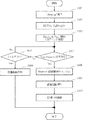
図7は、無線ルータ装置100の動作フローを示す図である。
FIG. 7 is a diagram illustrating an operation flow of the
図7に示されるように、まず、無線ルータ装置100を起動する(S701)。このとき、無線ルータ装置100では、電源回路制御部181は、通信モードで、電源回路部1500の電源供給を制御する。すなわち、通信モードでは、電源回路部150が、公衆網接続用通信部110、無線LAN通信部120およびメイン制御部170に対して電源供給を行い、ブルートゥース通信部130に対して電源供給を行わない。
As shown in FIG. 7, first, the
ここで、通信モードからスタンバイモードへ移行する条件として、次の2つが無線ルータ装置100に設定されているものとする。無線ルータ装置は、次の2つの条件のいずれか一方を満たせば、スタンバイモードへ移行する。
Here, it is assumed that the following two conditions are set in the
まず、1つ目の条件として、無線ルータ装置100と移動通信端末200との間でデータ通信が行われていない時間が所定の設定時間を超過した場合が、設定されている。
First, as a first condition, a case where a time during which data communication is not performed between the
次に、2つ目の条件として、無線ルータ装置100がスタンバイモードに移行する指示を受けた場合が、設定されている。
Next, the second condition is set when the
無線ルータ装置100がスタンバイモードに移行する指示を受けた場合とは、(1)スイッチ部190がスタンバイモードに切り替わるようにオフにされている場合と、(2)無線ルータ装置100が移動通信端末200からスタンバイモードに移行する指示を受信した場合の2つの場合である。
When the
S701の処理の後、メイン制御部160内の無通信タイムアウト判定部171は、無通信タイマがタイムアウトしたか否かを判断する(S702)。具体的には、無通信タイムアウト判定部171が、無線ルータ装置100と移動通信端末200との間でデータ通信が行われていない時間が所定の設定時間を超過したか否かを判断する。
After the processing of S701, the no-communication
メイン制御部160の無通信タイムアウト判定部171が、無線ルータ装置100と移動通信端末200との間でデータ通信が行われていない時間が所定の設定時間を超過したと判断した場合(S702、Yes)、モード移行信号発生部172がスタンバイモードへ移行を促す信号を生成し、これをサブ制御部180へ入力する。そして、サブ制御部180のモード移行監視部183は、スタンバイモードへ移行する指示が、来ていることを認識する。この認識を受けて、移動通信端末200は後述のS704の処理を行う。
When the no-communication
メイン制御部160の無通信タイムアウト判定部171が、無線ルータ装置100と移動通信端末200との間でデータ通信が行われていない時間が所定の設定時間を超過していないと判断した場合(S702、No)、メイン制御部160が、無線ルータ装置100がスタンバイモードに移行する指示を受けているか否かを判断する(S703)。
When the no-communication
すなわち、スイッチ監視部182はスイッチ部190がスタンバイモードに切り替わるようにオフにされているか否かを判断する。併せて、無線ルータ装置100が移動通信端末200からスタンバイモードに移行する指示を受信したか否かを判断する。すなわち、移動通信端末200は、スタンバイモードに移行する指示信号であるスタンバイ(Standby)信号を、公衆網(例えばWLAN)を介して、無線ルータ装置100へ送信する。無線ルータ装置100では、メイン制御部170が、公衆網接続用通信部110を用いて、前記スタンバイ信号を取得する。そして、モード移行信号発生部172が、スタンバイ信号に対応して、スタンバイモードへ移行を促す信号を生成し、これをサブ制御部180へ入力する。そして、サブ制御部180のモード移行監視部183は、スタンバイモードへ移行する指示が、来ていることを認識する。この認識を受けて、移動通信端末200は後述のS704の処理を行う。
That is, the switch monitoring unit 182 determines whether or not the
スイッチ監視部182により、スイッチ部190がスタンバイモードに切り替わるようにオフにされていると判断された場合(S703、Yes)、移動通信端末200は後述のS704の処理を行う。
When the switch monitoring unit 182 determines that the
同様に、無線ルータ装置100が移動通信端末200からスタンバイモードに移行する指示を受信したと、メイン制御部170により判断された場合(S703、Yes)、移動通信端末200は後述のS704の処理を行う。
Similarly, when the
一方、スイッチ部190がスタンバイモードに切り替わるようにオフにされていないと、メイン制御部170により判断された場合(S703、No)、移動通信端末200はS702の処理を再び行う。
On the other hand, if the
同様に、無線ルータ装置100が移動通信端末200からスタンバイモードに移行する指示を受信していないと、メイン制御部170により判断された場合(S703、No)、移動通信端末200はS702の処理を再び行う。
Similarly, when the
S702の処理でYesであった場合と、S703の処理でYesであった場合には、無線ルータ装置100では、電源回路制御部181は、スタンバイモードに切り替えて、電源回路部150の電源供給を制御する(S704)。この結果、スタンバイモード中では、電源回路部150が、ブルートゥース通信部130に電源供給を行い、公衆網接続用通信部110、無線LAN通信部130およびメイン制御部170に対して電源供給を行わない状態になる。これにより、無線ルータ装置100全体の消費電力を減少させることができる。
In the case of Yes in the processing of S702 and Yes in the processing of S703, in the
次に、Bluetooth Page Scanを開始する(S705)。具体的には、Bluetooth Page Scanが開始されると、無線ルータ装置100のブルートゥース通信部131が、当該無線ルータ装置100宛に接続要求(Page:呼び出し)がないか否かを監視する。この接続要求は、当該無線ルータ装置100の周囲に存在する移動通信端末100から送信される。なお、無線ルータ装置100は、移動通信端末200から接続要求があった場合、この接続要求に対してレスポンスを返す。
Next, Bluetooth Page Scan is started (S705). Specifically, when Bluetooth Page Scan is started, the
無線ルータ装置100は、移動通信端末200から接続要求があるか否かを判断する(S706)。具体的には、ブルートゥース通信部130内の接続要求判断部132が、無線ルータ装置100の周囲の移動通信端末200が当該無線ルータ装置100に対して接続の要求を行う接続要求(Page信号とも呼ばれる)があるか否かを判断する。
The
接続要求判断部132により接続要求があると判断された場合(S706、Yes)、識別情報存否判断部133が、接続要求(Page信号)内に、無線ルータ装置100のBDアドレス(識別情報)が含まれているか否かを判断する(S707)。このとき、当該無線ルータ装置100のBDアドレス(識別情報)は、ブルートゥース通信部130内の記憶部(不図示)に予め記憶されている。そして、識別情報存否判断部133は、ブルートゥース通信部130内の記憶部に記憶されたBDアドレスと、接続要求内のBDアドレスとを比較する処理を行う。
If the connection
一方、接続要求判断部132により接続要求がないと判断された場合(S706、No)、S705のBluetooth Page Scanを継続して、再びS706の処理を行う。
On the other hand, when the connection
識別情報存否判断部133により、無線ルータ装置100のBDアドレスが接続要求内に、含まれていると判断された場合(S707、Yes)、無線ルータ装置100はBluetooth Page Responseを移動通信端末200に対して送信する(S708)。
When the identification information presence /
一方、識別情報存否判断部133により、無線ルータ装置100のBDアドレスが接続要求内に、含まれていないと判断された場合(S707、No)、S705のBluetooth Page Scanを継続して、再びS707の処理を行う。
On the other hand, when the identification information presence /
次に、無線ルータ装置100は、起動トリガをオン(ON)にする(S709)。具体的には、まず、ブルートゥース通信部130内の起動トリガ発生部134は、電源回路制御部181が通信モードで電源回路部150を制御させるための起動トリガを生成する。そして、ブルートゥース通信部130は、起動トリガ発生部134により生成された起動トリガを、サブ制御部180へ入力する。サブ制御部180では、モード移行監視部183が、通信モードに切り替えることを確認する。
Next, the
次に、無線ルータ装置100は、ルータ起動処理を実施する(S710)。具体的には、電源回路制御部181が、ブルートゥース通信部130から受け取った起動トリガに従って、通信モードで電源回路部150を制御する。通信モード中では、電源回路部150が、公衆網接続用通信部110、無線LAN通信部120およびメイン制御部170に対して電源供給を行い、ブルートゥース通信部130に対して電源供給を行わない。すなわち、この通信モードに設定する際に、電源回路制御部181は、ブルートゥース通信部130に電源供給しないように、電源回路部150を制御する(S711)。
Next, the
このように、識別情報存否判断部133が接続要求内に当該無線ルータ装置100の識別情報(BDアドレス)が含まれている場合、ブルートゥース通信部130は、電源回路制御部181に対して、通信モードで電源回路部150を制御させるための起動トリガを入力し、電源回路制御部181は、起動トリガに従って、通信モードで電源回路部150を制御する。
Thus, when the identification information presence /
通信モードでは、電源回路部150が、公衆網接続用通信部110、無線LAN通信部120およびメイン制御部170に対して電源供給を行うが、ブルートゥース通信部130に対して電源供給を行わない。したがって、識別情報存否判断部133が接続要求内に当該無線ルータ装置100の識別情報(BDアドレス)が含まれている場合に、無線ルータ装置100は、移動通信端末200とペアリングすることはない。このため、任意のタイミングで移動通信端末100との接続を開始することが容易にできる。
In the communication mode, the power
以上、無線ルータ装置100側の動作について説明した。
The operation on the
さらに、この後の処理として、移動通信端末200側の動作について説明する。
Further, as the subsequent processing, the operation on the
図8は、無線ルータ装置100と通信する移動通信端末200の動作フローを示す図である。
FIG. 8 is a diagram illustrating an operation flow of the
まず、移動通信端末200側では、無線ルータ装置100がスタンバイモードで動作している状態で、「Wake up」ボタン293(図5を参照)が利用者によって押下される(S801)。
First, on the
S801の処理に対応して、メイン制御部270は、専用アプリケーション271(アプリ)内に保存されているBDアドレスを読み込む(S802)。メイン制御部270は、読み込んだBDアドレスを、ブルートゥース通信部230に入力する。
Corresponding to the processing of S801, the
そして、ブルートゥース通信部230は、メイン制御部270により入力されたBDアドレスを指定して、Bluetooth Page動作を開始する(S803)。このBluetooth Page動作では、ブルートゥース通信部230が、移動通信端末200の近くに存在する無線ルータ装置100に対して、接続要求を送信する。なお、無線ルータ装置100は、移動通信端末200から接続要求を受信した場合、この接続要求に対してレスポンスを返す。
Then, the
次に、移動通信端末200は、Page Response信号を受信したか否かを判断する(S804)。具体的には、メイン制御部270が、無線ルータ装置100からレスポンスを受け取ったか否かを判断する。
Next, the
移動通信端末200がPage Response信号を受信した場合(S804、Yes)、以降のBluetooth接続動作は不要となるため、移動通信端末200はBluetooth接続動作をキャンセルする(S805)。
When the
その後、移動通信端末200は、無線ルータ装置100の起動を待つ(S806)。すなわち、移動通信端末100は、無線ルータ装置100が通信モードでの動作を開始するまで待つ。
After that, the
そして、無線ルータ装置100が起動した後に、移動通信端末100は無線ルータ装置100に無線LANで接続してデータ通信を行い(S807)、処理を終了する。
Then, after the
一方、移動通信端末200がPage Response信号を受信しない場合(S804、Yes)、メイン制御部270は、Page Response信号をタイムアウトするまで待つ(S808)。すなわち、メイン制御部270は、S803の処理開始後に所定の時間が経過するか否かを待つ。
On the other hand, when the
タイムアウトした場合(S808、Yes)、移動通信端末200は、無線ルータ装置100を起動させることに失敗したと認識し(S809)、全ての処理を終了する。
When the time-out has occurred (S808, Yes), the
一方、タイムアウトしなかった場合(S808、No)、S804の処理を再び実行する。 On the other hand, if the timeout has not occurred (S808, No), the process of S804 is executed again.
以上の通り、本発明の第1の実施の形態における無線ルータ装置100は、ブルートゥース通信機能を有する移動通信端末200と通信する。無線ルータ装置100は、ブルートゥース通信部130と、無線LAN通信部120と、メイン制御部170と、電源回路部170と、電源回路制御部181と、接続要求判断部132と、識別情報存否判断部133とを備えている。
As described above, the
ブルートゥース通信部130は、移動通信端末200とブルートゥース通信を行う。無線LAN通信部120は、移動通信端末と無線LANにより通信する。メイン制御部170は、ブルートゥース通信部130および無線LAN通信部120のデータ通信を制御する。電源回路部150は、ブルートゥース通信部130、無線LAN通信部120およびメイン制御部170への電源を供給する。電源回路制御部181は、通信モードと、スタンバイモードとを切り替えて、電源回路部150の電源供給を制御する。このとき、通信モードとは、電源回路部150が、無線LAN通信部120およびメイン制御部170に対して電源供給を行い、ブルートゥース通信部130に電源供給を行わないモードである。スタンバイモードとは、電源回路部150が、ブルートゥース通信部130に電源供給を行い、無線LAN通信部120およびメイン制御部170に対して電源供給を行わないモードである。接続要求判断部132は、電源回路制御部181がスタンバイモードで電源回路部150を制御している場合に、当該無線ルータ装置100の周囲の移動通信端末200が無線ルータ装置100に対して接続の要求を行う接続要求があるか否かを判断する。識別情報存否判断部133は、接続要求判断部132により接続要求があると判断された場合、接続要求内に当該無線ルータ装置100の識別情報(BDアドレス)が含まれているか否かを判断する。
The
そして、識別情報存否判断部133が接続要求内に当該無線ルータ装置100の識別情報(BDアドレス)が含まれていると判断した場合、ブルートゥース通信部130は、電源回路制御部181に対して、通信モードで電源回路部150を制御させるための起動トリガを入力し、電源回路制御部181は、起動トリガに従って、通信モードで電源回路部150を制御する。
When the identification information presence /
このように、本発明の第1の実施の形態における無線ルータ装置100では、電源回路制御部181は、通信モードと、スタンバイモードとを切り替えて、電源回路部150の電源供給を制御する。このとき、通信モードは、電源回路部150が、無線LAN通信部120およびメイン制御部170に対して電源供給を行い、ブルートゥース通信部130に電源供給を行わないモードである。スタンバイモードは、電源回路部150が、ブルートゥース通信部130に電源供給を行い、無線LAN通信部120およびメイン制御部170に対して電源供給を行わないモードである。スタンバイモードでは、無線LAN通信部120やブルートゥース通信部130と比較して非常に大きな電力を消費するメイン制御部170に対して電源供給を行わない。このため、スタンバイモード時には、通信モードと比較して、消費電力を減少させることができる。
As described above, in the
また、接続要求判断部132は、電源回路制御部181がスタンバイモードで電源回路部150を制御している場合に、接続要求があるか否かを判断する。これにより、無線ルータ装置100は、スタンバイモードで動作している間であっても、周囲の移動通信端末200からの接続要求の有無を確認することができる。
The connection
また、識別情報存否判断部133は、接続要求判断部132により接続要求があると判断された場合、接続要求内に当該無線ルータ装置100の識別情報(BDアドレス)が含まれているか否かを判断する。これにより、接続要求している移動通信端末200が、接続許可できるブルートゥース機器であるか否かを判断することができる。
Further, when the connection
そして、識別情報存否判断部133が接続要求内に当該無線ルータ装置100の識別情報(BDアドレス)が含まれていると判断した場合、ブルートゥース通信部130は、電源回路制御部181に対して、通信モードで電源回路部150を制御させるための起動トリガを入力し、電源回路制御部181は、起動トリガに従って、通信モードで電源回路部150を制御する。
When the identification information presence /
ここで、通信モードでは、電源回路部150が、公衆網接続用通信部110、無線LAN通信部120およびメイン制御部170に対して電源供給を行うが、ブルートゥース通信部130に対して電源供給を行わない。したがって、識別情報存否判断部133が接続要求内に当該無線ルータ装置100の識別情報(BDアドレス)が含まれていても、無線ルータ装置100は、移動通信端末200とペアリングすることはない。このため、ブルートゥースの接続開始を起動トリガとして、任意のタイミングで移動通信端末100との接続(無線LAN通信)を開始することが容易にできる。そして、ペアリング登録された無線ルータ装置100と移動通信端末200が自動的に接続を開始してしまうことはない。
Here, in the communication mode, the power
以上の通り、本発明の第1の実施の形態における無線ルータ装置100によれば、他のブルートゥース通信機能を有する機器とペアリングすることなく、ブルートゥースの接続開始を起動トリガとして、簡単に起動(無線LAN通信できる状態にする)ことができる。
As described above, according to the
また、特定のブルートゥース通信機能を有する移動通信端末200からのみのブルートゥース通信接続を、当該無線ルータ装置100の起動トリガとして用いることができるので、消費電力の小さいブルートゥース通信部130による待ち受けが可能となり、利便性と省電力化の双方を実現できる。
Further, since a Bluetooth communication connection only from the
また、上述の通り、他のブルートゥース通信機能を有する移動通信端末200とペアリングすることが必要なく、プロファイルによる認証も必要ない。このため、ホスト(メイン制御部170)を介在させることなく、コントローラ(ブルートゥース通信部130などの通信モジュール)とサブ制御部180だけで無線ルータ装置100の起動を制御できる。この結果、無線ルータ装置100の構成を簡略化できる。
Further, as described above, it is not necessary to perform pairing with the
さらに、電源回路制御部181はスタンバイモード時にはコントローラ(ブルートゥース通信部130などの通信モジュール)だけを制御するため、ブルートゥース通信部130は、無線ルータ装置100の起動を開始するための起動トリガを素早く出力できる。
Furthermore, since the power supply
また、本発明の第1の実施の形態における無線ルータ装置100は、通信接続される移動通信端末200を公衆網に接続する公衆網接続用通信部110をさらに備えてもよい。このとき、電源回路部150は、ブルートゥース通信部130、無線LAN通信部120、公衆網接続用通信部110およびメイン制御部170への電源を供給する。電源回路制御部181は、通信モードと、スタンバイモードとを切り替えて、電源回路部150の電源供給を制御する。この場合の通信モードは、電源回路部150が、無線LAN通信部130、公衆網接続用通信部110およびメイン制御部170に対して電源供給を行い、ブルートゥース通信部130に電源供給を行わないモードである。スタンバイモードは、電源回路部150が、ブルートゥース通信部130に電源供給を行い、無線LAN通信部120、公衆網接続用通信部110およびメイン制御部170に対して電源供給を行わないモードである。このような構成であっても、前述した効果と同様の効果を奏する。
In addition, the
本発明の第1の実施の形態における無線ルータ装置100において、電源回路制御部181は、無線ルータ装置100と移動通信端末200との間でデータ通信が行われていない時間が所定の設定時間を超過した場合、または無線ルータ装置100がスタンバイモードに移行する指示を受けた場合に、スタンバイモードで電源回路部150を制御する。
In the
このように、無線ルータ装置100と移動通信端末200との間でデータ通信が行われていない時間が所定の設定時間を超過した場合にスタンバイモードに移行することで、当該無線ルータ装置100の利用者の意思に関係なく、自動的に無線ルータ装置100の消費電力を減少させることができる。また、無線ルータ装置100がスタンバイモードに移行する指示を受けた場合にスタンバイモードに移行することで、当該無線ルータ装置100の利用者の意思に沿って、無線ルータ装置100の消費電力を減少させることができる。
As described above, when the time during which data communication is not performed between the
本発明の第1の実施の形態における無線ルータ装置100は、移動通信端末200の要求に応じて、当該無線ルータ装置100の識別情報(BDアドレス)を移動通信端末200へ送信する。これにより、移動通信端末200は、無線ルータ装置100の識別情報(BDアドレス)を容易に取得でき、この識別情報を用いて容易に無線ルータ装置100と通信接続することができる。
The
<第2の実施の形態>
次に、本発明の第2の実施の形態における無線ルータ装置について、説明する。
<Second Embodiment>
Next, a wireless router apparatus according to the second embodiment of the present invention will be described.
なお、本発明の第2の実施の形態における無線ルータ装置の基本構成は、第1の実施の形態における無線ルータ100と同一である。また、本発明の第2の実施の形態における無線ルータ装置と通信接続する移動通信端末の基本構成も、第1の実施の形態で説明した移動通信端末200と同一である。このため、本実施の形態における無線ルータ装置および移動通信端末を、無線ルータ装置100および移動通信端末200として、説明する。
The basic configuration of the wireless router device according to the second embodiment of the present invention is the same as that of the
本実施の形態では、移動通信端末200が、識別情報(BDアドレス)をアプリ(専用アプリケーション271)に登録する場合であって、無線LAN通信で自動設定機能を実行している際に、同時にBDアドレスを取得する方法を説明する。
In the present embodiment, the
無線LAN通信機能を有する装置には、WPS(Wi-Fi Protected Setup)や、「らくらく無線スタート(登録商標)」のように、SSID(Service Set Identifier)や暗号化キーを直接入力しなくても、半自動的に無線LANの設定を行うことができる機能を有するものがある。移動通信端末200側で使用するアプリケーションに、これらの機能を組み込むことにより、無線LANの設定と同時に、BDアドレスを取得することができる。
It is not necessary to directly input an SSID (Service Set Identifier) or encryption key to a device having a wireless LAN communication function, such as WPS (Wi-Fi Protected Setup) or “Easy Wireless Start (registered trademark)”. Some have a function of setting a wireless LAN semi-automatically. By incorporating these functions into the application used on the
図9は、本発明の第2の実施の形態における無線ルータ装置100と通信する移動通信端末200の動作フローを示す。
FIG. 9 shows an operation flow of
図9に示されるように、移動通信端末200側では、メイン制御部270が、無線LAN自動設定を開始する(S901)。
As shown in FIG. 9, on the
メイン制御部270が無線LAN自動設定を完了すると(S902)、S902で設定した無線LANで通信を開始する(S903)。
When the
次に、移動通信端末200は、無線ルータ装置100に対して、当該無線ルータ装置100のBDアドレスの要求信号を送信する(S904)。BDアドレスの要求信号を受け取った無線ルータ装置100は、移動通信端末200に対して、当該無線ルータ装置100のBDアドレスを送信する。
Next, the
次に、移動通信端末200は、無線ルータ装置100から、BDアドレスを受信する(S905)。
Next, the
そして、移動通信端末200では、メイン制御部270が、専用アプリケーション271に登録する形で、BDアドレスを記憶部260に記録する。
Then, in the
これにより、移動通信端末200が、識別情報(BDアドレス)をアプリ(専用アプリケーション271)に登録する場合に合わせて、無線LAN通信で自動設定機能を実行している際に、同時にBDアドレスを取得することができる。
Thereby, when the
<第3の実施の形態>
次に、本発明の第3の実施の形態における無線ルータ装置について、説明する。
<Third Embodiment>
Next, a wireless router device according to the third embodiment of the present invention will be described.
なお、本発明の第3の実施の形態における無線ルータ装置の基本構成は、第1の実施の形態における無線ルータ100と同一である。また、本発明の第2の実施の形態における無線ルータ装置と通信接続する移動通信端末の基本構成も、第1の実施の形態で説明した移動通信端末200と同一である。このため、本実施の形態における無線ルータ装置および移動通信端末を、無線ルータ装置100および移動通信端末200として、説明する。
The basic configuration of the wireless router device according to the third embodiment of the present invention is the same as that of the
本発明の第3の実施の形態では、移動通信端末100が無線ルータ装置100のBDアドレス(識別情報)をアプリケーションに登録する際に、QRコード(登録商標)を用いる例を説明する。
In the third embodiment of the present invention, an example will be described in which the
図10は、QRコード900の一例を示す。
FIG. 10 shows an example of the
図10に示されるように、QRコード900は、マトリックス型二次元式のバーコードである。なお、「QR」はQuik Responseに由来する。また、QRコード510は、一次元バーコードと異なり、一般的に縦横に情報を有し、格納できる情報量が多い。このため、QRコード510は、数字だけでなく、英字や漢字などの多言語のデータも格納できる特徴がある。なお、QRコード510は、本発明のバーコードに対応する。
As shown in FIG. 10, the
図10に示されるように、QRコード900は、少なくとも、無線ルータ装置100のBDアドレスの情報を含んでいる。
As shown in FIG. 10, the
QRコード900は、例えば、無線ルータ装置100の表示部(不図示)に表示される。なお、表示部は、例えば、液晶表示装置や有機EL表示装置などである。このとき、無線ルータ装置100に接続されたPCの表示画面に、QRコード900を表示するようにしてもよい。
The
また、QRコード900を予め無線ルータ装置100に貼り付けるラベルシートに印刷しておいて、これを無線ルータ装置100の筐体に貼り付けてもよい。
Alternatively, the
一方、移動通信端末200は、少なくとも撮像部(不図示)を有する。この撮像部は、QRコード900を撮像することができる。また、移動通信端末200は、撮像部により撮像されたQRコード900中からBDアドレスを抽出する機能を有する。
On the other hand, the
移動通信端末200を用いて、QRコード900からBDアドレスを取得する方法を説明する。ここでは、QRコード900は、無線ルータ装置100の表示部に表示されているものとする。
A method for acquiring a BD address from the
まず、移動通信端末200の撮像部が、無線ルータ装置100の表示部に表示されたQRコード900を撮像する。移動通信端末200は、撮像部により撮像されたQRコード900中に含まれるBDアドレスの情報を取得する。これにより、移動通信端末200は、無線ルータ装置100のBDアドレスを取得できる。そして、メイン制御部270は、取得したBDアドレスを記憶部260に記憶する。
First, the imaging unit of the
このように、本発明の第3の実施の形態における無線ルータ装置100は、当該無線ルータ100のBDアドレス(識別情報)を含む所定のQRコード900(バーコード情報)を有し、QRコード900を移動通信端末200の利用者へ表示提供する。これにより、移動通信端末200の利用者は、QRコードを撮像するだけで、BDアドレスを移動通信端末200に取り込むことができる。この結果、移動通信端末200は、無線ルータ装置100のBDアドレスを取得できる。
As described above, the
<第4の実施の形態>
次に、本発明の第4の実施の形態における無線ルータ装置について、説明する。
<Fourth embodiment>
Next, a wireless router device according to a fourth embodiment of the present invention will be described.
なお、本発明の第4の実施の形態における無線ルータ装置の基本構成は、第1の実施の形態における無線ルータ100と同一である。また、本発明の第2の実施の形態における無線ルータ装置と通信接続する移動通信端末の基本構成も、第1の実施の形態で説明した移動通信端末200と同一である。このため、本実施の形態における無線ルータ装置および移動通信端末を、無線ルータ装置100および移動通信端末200として、説明する。
The basic configuration of the wireless router device according to the fourth embodiment of the present invention is the same as that of the
第1の実施の形態では、無線ルータ装置100のBDアドレスを、無線ルータ装置100の識別情報として用いて、ブルートゥース通信を実現していた。これに対して、本実施の形態では、無線ルータ装置100のデバイス名を、無線ルータ装置100の識別情報として用いて、ブルートゥース通信を実現する。
In the first embodiment, Bluetooth communication is realized using the BD address of the
移動通信端末200側で、ブルートゥース通信に必要なデバイス名(識別情報)を取得する方法を説明する。
A method for acquiring a device name (identification information) necessary for Bluetooth communication on the
図11は、本実施の形態における移動通信端末200の動作フローを示す図である。
FIG. 11 is a diagram showing an operation flow of
図11に示されるように、移動通信端末200側では、まず、アプリを起動する(ステップ(S1101)。具体的には、移動通信端末200内では、メイン制御部270が、専用のアプリケーション271を起動する。
11, on the
次に、メイン制御部270が、デバイス名がアプリ内に登録されているか否かを確認する(S1102)。
Next, the
デバイス名がアプリ内に登録されている場合(S1102、Yes)、処理を終了する。 If the device name is registered in the application (S1102, Yes), the process ends.
デバイス名がアプリ内に登録されていない場合(S1102、No)、移動通信端末200は、無線ルータ装置100に対して、デバイス名取得の要求を行う(S1103)。より具体的には、メイン制御部270が、デバイス名取得の要求信号を生成する。そして、メイン制御部270は、無線LAN通信部220に対して、デバイス名取得の要求信号を無線ルータ装置100へ送信するように、指示する。そして、無線LAN通信部220が、デバイス名得の要求信号を、無線LAN通信を介して、無線ルータ装置100へ送信する。
When the device name is not registered in the application (S1102, No), the
次に、移動通信端末200は、無線ルータ装置100からデバイス名のデータを受信する(S1104)。具体的には、無線LAN通信部220が、無線ルータ装置100から送信されたデバイス名のデータを受信し、これをメイン制御部170へ入力する。
Next, the
そして、メイン制御部270は、取得したデバイス名を、アプリの登録に対応付けて、記憶部260に記憶する(S1105)。これにより、無線ルータ装置100のデバイス名が、移動通信端末200内に記憶される。
Then, the
以上の通り、本発明の第4の実施の形態における無線ルータ装置100において、無線ルータ装置100の識別情報は、当該無線ルータ装置100固有のデバイス名である。このように、無線ルータ装置100の識別情報に、当該無線ルータ装置100固有のデバイス名を用いても、移動通信端末200および無線ルータ装置100の間のブルートゥース通信を実現することができる。
As described above, in the
以上、実施の形態をもとに本発明を説明した。実施の形態は例示であり、本発明の主旨から逸脱しない限り、上述各実施の形態に対して、さまざまな変更、増減、組合せを加えてもよい。これらの変更、増減、組合せが加えられた変形例も本発明の範囲にあることは当業者に理解されるところである。 The present invention has been described above based on the embodiment. The embodiment is an exemplification, and various modifications, increases / decreases, and combinations may be added to the above-described embodiments without departing from the gist of the present invention. It will be understood by those skilled in the art that modifications to which these changes, increases / decreases, and combinations are also within the scope of the present invention.
100 無線ルータ装置
110 公衆網接続用通信部
111 公衆網接続用通信部用アンテナ部
120 無線LAN通信部
121 無線LAN通信部用アンテナ部
130 ブルートゥース通信部
131 ブルートゥース通信部用アンテナ部
132 接続要求判断部
133 識別情報存否判断部
134 起動トリガ発生部
135 無線部
136 リンクコントローラ
137 LMP
138 HCI
140 バッテリ部
150 電源回路部
160 記憶部
170 メイン制御部
171 無通信タイムアウト判定部
172 モード移行信号発生部
173 HCI
174 Bluetoothプロトコルスタック
175 OS
180 サブ制御部
181 電源回路制御部
190 スイッチ部
200 移動通信端末
220 無線LAN通信部
221 無線LAN通信部用アンテナ部
230 ブルートゥース通信部
231 ブルートゥース通信部用アンテナ部
270 メイン制御部
271 専用アプリケーション
300 無線WAN基地局
301 無線WAN通信用アンテナ
DESCRIPTION OF
138 HCI
140
174
180
Claims (6)
前記移動通信端末とブルートゥース通信を行うブルートゥース通信部と、
前記移動通信端末と無線LANにより通信する無線LAN通信部と、
前記ブルートゥース通信部および前記無線LAN通信部のデータ通信を制御するメイン制御部と、
前記ブルートゥース通信部、前記無線LAN通信部および前記メイン制御部への電源を供給する電源回路部と、
前記電源回路部が、前記無線LAN通信部および前記メイン制御部に対して電源供給を行い、前記ブルートゥース通信部に電源供給を行わないモードである通信モードと、前記電源回路部が、前記ブルートゥース通信部に電源供給を行い、前記無線LAN通信部および前記メイン制御部に対して電源供給を行わないモードであるスタンバイモードとを切り替えて、前記電源回路部の電源供給を制御する電源回路制御部と、
前記電源回路制御部が前記スタンバイモードで前記電源回路部を制御している場合に、当該無線ルータ装置の周囲の前記移動通信端末が前記無線ルータ装置に対して接続の要求を行う接続要求があるか否かを判断する接続要求判断部と、
前記接続要求判断部により前記接続要求があると判断された場合、前記接続要求内に当該無線ルータ装置の識別情報が含まれているか否かを判断する識別情報存否判断部とを備え、
前記識別情報存否判断部が前記接続要求内に当該無線ルータ装置の識別情報が含まれていると判断した場合、前記ブルートゥース通信部は、前記電源回路制御部に対して、前記通信モードで前記電源回路部を制御させるための起動トリガを入力し、前記電源回路制御部は、前記起動トリガに従って、前記通信モードで前記電源回路部を制御する無線ルータ装置。 A wireless router device that communicates with a mobile communication terminal having a Bluetooth communication function,
A Bluetooth communication unit for performing Bluetooth communication with the mobile communication terminal;
A wireless LAN communication unit for communicating with the mobile communication terminal by a wireless LAN;
A main control unit for controlling data communication of the Bluetooth communication unit and the wireless LAN communication unit;
A power supply circuit unit that supplies power to the Bluetooth communication unit, the wireless LAN communication unit, and the main control unit;
A communication mode in which the power supply circuit unit supplies power to the wireless LAN communication unit and the main control unit and power is not supplied to the Bluetooth communication unit; and the power supply circuit unit includes the Bluetooth communication. A power supply circuit control unit that controls power supply of the power supply circuit unit by switching power supply to the wireless LAN communication unit and a standby mode that does not supply power to the main control unit. ,
When the power supply circuit control unit controls the power supply circuit unit in the standby mode, there is a connection request for the mobile communication terminal around the wireless router device to make a connection request to the wireless router device A connection request determination unit for determining whether or not
An identification information presence / absence determining unit that determines whether or not the wireless router device identification information is included in the connection request when the connection request determining unit determines that the connection request is present;
When the identification information presence / absence determination unit determines that the identification information of the wireless router device is included in the connection request, the Bluetooth communication unit transmits the power supply in the communication mode to the power supply circuit control unit. A wireless router device that receives a start trigger for controlling a circuit unit, and wherein the power supply circuit control unit controls the power supply circuit unit in the communication mode in accordance with the start trigger.
前記電源回路部は、前記ブルートゥース通信部、前記無線LAN通信部、前記公衆網接続用通信部および前記メイン制御部への電源を供給し、
前記電源回路制御部は、前記電源回路部が、前記無線LAN通信部、前記公衆網接続用通信部および前記メイン制御部に対して電源供給を行うモードである通信モードと、前記電源回路部が、前記ブルートゥース通信部に電源供給を行い、前記無線LAN通信部、前記公衆網接続用通信部および前記メイン制御部に対して電源供給を行わないモードであるスタンバイモードとを切り替えて、前記電源回路部の電源供給を制御する請求項1に記載の無線ルータ装置。 Further comprising a public network connection communication unit for connecting the mobile communication terminal to be connected to the public network,
The power supply circuit unit supplies power to the Bluetooth communication unit, the wireless LAN communication unit, the public network connection communication unit, and the main control unit,
The power supply circuit control unit includes a communication mode in which the power supply circuit unit supplies power to the wireless LAN communication unit, the public network connection communication unit, and the main control unit, and the power supply circuit unit includes: Switching the power supply circuit to a standby mode, which is a mode in which power is supplied to the Bluetooth communication unit and power is not supplied to the wireless LAN communication unit, the public network connection communication unit, and the main control unit. The wireless router device according to claim 1, which controls power supply of a unit.
Priority Applications (1)
| Application Number | Priority Date | Filing Date | Title |
|---|---|---|---|
| JP2012196174A JP5960558B2 (en) | 2012-09-06 | 2012-09-06 | Wireless router device |
Applications Claiming Priority (1)
| Application Number | Priority Date | Filing Date | Title |
|---|---|---|---|
| JP2012196174A JP5960558B2 (en) | 2012-09-06 | 2012-09-06 | Wireless router device |
Publications (2)
| Publication Number | Publication Date |
|---|---|
| JP2014053725A JP2014053725A (en) | 2014-03-20 |
| JP5960558B2 true JP5960558B2 (en) | 2016-08-02 |
Family
ID=50611810
Family Applications (1)
| Application Number | Title | Priority Date | Filing Date |
|---|---|---|---|
| JP2012196174A Active JP5960558B2 (en) | 2012-09-06 | 2012-09-06 | Wireless router device |
Country Status (1)
| Country | Link |
|---|---|
| JP (1) | JP5960558B2 (en) |
Families Citing this family (9)
| Publication number | Priority date | Publication date | Assignee | Title |
|---|---|---|---|---|
| JP5722853B2 (en) * | 2012-09-18 | 2015-05-27 | Necプラットフォームズ株式会社 | COMMUNICATION DEVICE AND COMMUNICATION DEVICE CONTROL METHOD |
| CN104244239A (en) * | 2013-06-06 | 2014-12-24 | 中兴通讯股份有限公司 | Mobile hotspot starting device, method and system |
| JP2015046679A (en) * | 2013-08-27 | 2015-03-12 | Necプラットフォームズ株式会社 | Radio relay device, method and program for controlling operation mode, radio communication system and radio terminal |
| JP6246353B2 (en) * | 2014-06-09 | 2017-12-13 | 株式会社Nttドコモ | Communication apparatus and communication control method |
| CN105307184A (en) * | 2014-06-17 | 2016-02-03 | 中兴通讯股份有限公司 | Method, device and system for managing mobile hotspots |
| JP6475043B2 (en) * | 2015-03-09 | 2019-02-27 | Necプラットフォームズ株式会社 | COMMUNICATION DEVICE, COMMUNICATION SYSTEM, COMMUNICATION METHOD, AND PROGRAM |
| JP6558527B2 (en) * | 2015-03-30 | 2019-08-14 | カシオ計算機株式会社 | Electronic device, electronic device control method, program, and wireless communication system |
| JP6776679B2 (en) * | 2016-07-15 | 2020-10-28 | セイコーエプソン株式会社 | Wireless communication device, printing device, and control method |
| JP2019078758A (en) * | 2018-12-25 | 2019-05-23 | 株式会社ユピテル | Imaging apparatus and imaging system |
Family Cites Families (4)
| Publication number | Priority date | Publication date | Assignee | Title |
|---|---|---|---|---|
| JP4081679B2 (en) * | 2003-06-20 | 2008-04-30 | 日本電気株式会社 | Wireless communication system |
| JP2006074615A (en) * | 2004-09-03 | 2006-03-16 | Toshiba Corp | Information processor |
| JP5002669B2 (en) * | 2010-03-12 | 2012-08-15 | 株式会社東芝 | Communication equipment |
| US20110158212A1 (en) * | 2009-12-28 | 2011-06-30 | Kabushiki Kaisha Toshiba | Communication device and wireless communication connection method |
-
2012
- 2012-09-06 JP JP2012196174A patent/JP5960558B2/en active Active
Also Published As
| Publication number | Publication date |
|---|---|
| JP2014053725A (en) | 2014-03-20 |
Similar Documents
| Publication | Publication Date | Title |
|---|---|---|
| JP5960558B2 (en) | Wireless router device | |
| US11792632B2 (en) | Communicating apparatus, communication method, and storage medium storing program | |
| JP6650004B2 (en) | Communication system, program, and communication method | |
| US9258836B2 (en) | Information processing apparatus, control method therefor, and recording medium | |
| US9313363B2 (en) | Information processing apparatus, control methods, and storage medium for printing using short distance wireless communication | |
| KR101803709B1 (en) | Communication apparatus, terminal apparatus, control methods thereof, and computer-readable storage medium | |
| JP6524717B2 (en) | Electronic device, communication mode control method and communication mode control program | |
| JP6216149B2 (en) | COMMUNICATION DEVICE, COMMUNICATION METHOD, AND PROGRAM | |
| JP6305023B2 (en) | COMMUNICATION DEVICE, COMMUNICATION DEVICE CONTROL METHOD, AND PROGRAM | |
| JP2013187566A (en) | Network system, information processing device, scanner device, and communication method | |
| KR102482670B1 (en) | An electronic device for transmitting and receiving data in a wireless communication system and a method thereof | |
| US10827540B2 (en) | Communication apparatus that can communicate with a device provided with an access point, and control method therefor | |
| KR102361852B1 (en) | Communication apparatus, control method, and medium | |
| JP6344891B2 (en) | Control device, electronic device, control method, and program | |
| EP3739838B1 (en) | Method for establishing network connection by using wps and mobile wi-fi device and computer storage medium | |
| JP6282364B2 (en) | COMMUNICATION DEVICE, PROGRAM, AND COMMUNICATION SYSTEM | |
| JP2014187654A (en) | Information processing system, information processing device, and program | |
| US10306455B2 (en) | Communication apparatus, communication method, and non-transitory computer-readable storage medium | |
| JP7303913B2 (en) | Communication device, control method, and program | |
| JP6559022B2 (en) | COMMUNICATION DEVICE, COMMUNICATION DEVICE CONTROL METHOD, COMPUTER PROGRAM | |
| JP2015220587A (en) | Radio communication system, communication method of the same, and program | |
| JP2017103800A (en) | Communication device, information terminal, control method therefor, and program | |
| JP2016178461A (en) | Communication device and control method of the same, and program |
Legal Events
| Date | Code | Title | Description |
|---|---|---|---|
| A711 | Notification of change in applicant |
Free format text: JAPANESE INTERMEDIATE CODE: A712 Effective date: 20140805 |
|
| A621 | Written request for application examination |
Free format text: JAPANESE INTERMEDIATE CODE: A621 Effective date: 20150824 |
|
| TRDD | Decision of grant or rejection written | ||
| A01 | Written decision to grant a patent or to grant a registration (utility model) |
Free format text: JAPANESE INTERMEDIATE CODE: A01 Effective date: 20160531 |
|
| A977 | Report on retrieval |
Free format text: JAPANESE INTERMEDIATE CODE: A971007 Effective date: 20160531 |
|
| A61 | First payment of annual fees (during grant procedure) |
Free format text: JAPANESE INTERMEDIATE CODE: A61 Effective date: 20160623 |
|
| R150 | Certificate of patent or registration of utility model |
Ref document number: 5960558 Country of ref document: JP Free format text: JAPANESE INTERMEDIATE CODE: R150 |