JP5960200B2 - Needle protection device - Google Patents
Needle protection device Download PDFInfo
- Publication number
- JP5960200B2 JP5960200B2 JP2014137852A JP2014137852A JP5960200B2 JP 5960200 B2 JP5960200 B2 JP 5960200B2 JP 2014137852 A JP2014137852 A JP 2014137852A JP 2014137852 A JP2014137852 A JP 2014137852A JP 5960200 B2 JP5960200 B2 JP 5960200B2
- Authority
- JP
- Japan
- Prior art keywords
- protection device
- needle
- inner case
- outer case
- case
- Prior art date
- Legal status (The legal status is an assumption and is not a legal conclusion. Google has not performed a legal analysis and makes no representation as to the accuracy of the status listed.)
- Active
Links
Images


Classifications
-
- A—HUMAN NECESSITIES
- A61—MEDICAL OR VETERINARY SCIENCE; HYGIENE
- A61M—DEVICES FOR INTRODUCING MEDIA INTO, OR ONTO, THE BODY; DEVICES FOR TRANSDUCING BODY MEDIA OR FOR TAKING MEDIA FROM THE BODY; DEVICES FOR PRODUCING OR ENDING SLEEP OR STUPOR
- A61M5/00—Devices for bringing media into the body in a subcutaneous, intra-vascular or intramuscular way; Accessories therefor, e.g. filling or cleaning devices, arm-rests
- A61M5/178—Syringes
- A61M5/31—Details
- A61M5/32—Needles; Details of needles pertaining to their connection with syringe or hub; Accessories for bringing the needle into, or holding the needle on, the body; Devices for protection of needles
- A61M5/3202—Devices for protection of the needle before use, e.g. caps
-
- A—HUMAN NECESSITIES
- A61—MEDICAL OR VETERINARY SCIENCE; HYGIENE
- A61M—DEVICES FOR INTRODUCING MEDIA INTO, OR ONTO, THE BODY; DEVICES FOR TRANSDUCING BODY MEDIA OR FOR TAKING MEDIA FROM THE BODY; DEVICES FOR PRODUCING OR ENDING SLEEP OR STUPOR
- A61M5/00—Devices for bringing media into the body in a subcutaneous, intra-vascular or intramuscular way; Accessories therefor, e.g. filling or cleaning devices, arm-rests
- A61M5/178—Syringes
- A61M5/31—Details
- A61M2005/3103—Leak prevention means for distal end of syringes, i.e. syringe end for mounting a needle
- A61M2005/3107—Leak prevention means for distal end of syringes, i.e. syringe end for mounting a needle for needles
- A61M2005/3109—Caps sealing the needle bore by use of, e.g. air-hardening adhesive, elastomer or epoxy resin
Description
本発明は、注入デバイスあるいはアセンブリの針を保護するデバイスに関するものである。 The present invention relates to an infusion device or device for protecting an assembly needle.
本願において、ピースあるいはデバイスの遠位端とはユーザの手から最も遠い端部を言うものとして理解すべきであり、近位端とはユーザの手に最も近い端部を言うものとして理解すべきである。同様に、本願において、「遠位方向」とは注入の方向を言うものとして理解すべきであり、近位方向とは注入の方向とは反対の方向を言うものとして理解すべきである。 In this application, the distal end of a piece or device should be understood as meaning the end furthest from the user's hand, and the proximal end should be understood as meaning the end closest to the user's hand. It is. Similarly, in this application, the “distal direction” should be understood as referring to the direction of injection, and the proximal direction should be understood as referring to the direction opposite to the direction of injection.
例えば注射器などの注入デバイスは、針が存在していることから、使用の前後に注意深く取り扱わなければならない。針の突き刺しによる不慮の負傷の危険を最小限にするために、注射器は一般に、針の尖鋭端を覆う針シールドをもつハブを装備している。針シールドは、針の尖鋭端を露出させるべく使用に先立って取り外される。かかるシールドは、針の尖鋭端を保護するための、また注入デバイスの使用前に針を無菌状態に保つための機能も果たす。 For example, injection devices such as syringes must be handled carefully before and after use due to the presence of needles. In order to minimize the risk of accidental injury from needle sticks, syringes are typically equipped with a hub with a needle shield that covers the sharp end of the needle. The needle shield is removed prior to use to expose the sharp tip of the needle. Such a shield also serves to protect the sharp tip of the needle and to keep the needle sterile before using the infusion device.
注射器ハブと針シールドとの間にシールが存在していることから、注射器からの針シールドの取り外しによって注射器内に収容されている薬液の一部の吸出(aspiration)が引き起こされることがあり、この吸出分は注入の損失となるものである。薬剤を標準容量分(すなわちミリリットル単位で)注入する場合、かかる現象はさほど重要ではない。針シールドの取り外しを通じて吸出される量は、一般には、注入されるべき薬液の完全な用量に対して無視できる量であるからである。 Due to the presence of a seal between the syringe hub and the needle shield, removal of the needle shield from the syringe can cause aspiration of a portion of the drug solution contained within the syringe. The sucked-out amount is a loss of injection. This phenomenon is less important when the drug is injected in a standard volume (ie in milliliters). This is because the amount aspirated through removal of the needle shield is generally negligible relative to the complete dose of the drug solution to be injected.
しかしながら、一般的には0.5〜3mmの範囲の短い針が注射器に設けられ、かつ比較的少ない用量の薬液が注射器内に移送されて患者に注入されるような皮内注入を行う場合、いかなる量であっても、薬液の吸出は、企図されている用量に対しかなりの損失を意味する。かかる皮内注入を正確に行う場合、例えばワクチン注射を行う場合に関して言えば、投与されるのに必要な容量の安定性を確保することが特に重要である。かかる吸出は注入の再現性を阻害するものともなる。薬液のいくらかの吸出によって用量が一貫しなくなり得るからである。 However, when performing intradermal injections where a short needle, typically in the range of 0.5-3 mm, is provided in the syringe and a relatively small dose of drug solution is transferred into the syringe and injected into the patient, Whatever the amount, inhalation of the drug solution represents a significant loss for the intended dose. It is particularly important to ensure the stability of the volume required to be administered when performing such intradermal injections accurately, for example when performing vaccine injections. Such a suction also hinders the reproducibility of the injection. This is because some inhalation of the drug solution can make the dose inconsistent.
針シールドは、概ね柔軟な部分と概ね剛性のある部分とを有している。概ね柔軟な部分によって、少なくとも封止線に沿った注射器との密封結合が可能となり、概ね剛性のある部分によって、不慮の針の突き刺しに対する保護が行われるとともに、ユーザが注射器から針シールドを取り外すために把持可能な表面が提供される。 The needle shield has a generally flexible portion and a generally rigid portion. The generally flexible portion allows a hermetic connection with the syringe at least along the seal line, and the generally rigid portion provides protection against accidental needle sticks and allows the user to remove the needle shield from the syringe. A grippable surface is provided.
従って、注入デバイスや、注入デバイスまたはアセンブリに組み立てられることが企図された針アセンブリの針に対する針シールドなどの保護デバイスには、これが注入を実行するための注入デバイスの使用に先立って注入デバイスから取り外される際に、薬液の吸出を制限ひいては阻止するものであることが求められる。 Thus, a protective device such as a needle shield against the needle of an injection device or needle assembly intended to be assembled to an injection device or assembly is removed from the injection device prior to use of the injection device to perform the injection. In this case, it is required to limit and prevent the suction of the chemical solution.
本発明は、注入デバイスまたはアセンブリから取り外される際の薬液の吸出を制限する保護デバイスを提供することによって、この問題を解決する。本発明の保護デバイスは、固定された針(すなわち注射器から取り外し不能に固定された針)を有する注入デバイスや、例えばルアー結合(Luer connection)によって取り付けられた針アセンブリなどの取り外し可能な針を有する注入デバイスに用いることができるものである。加えて、本発明は特に、例えば皮内注射など少用量を供給することが企図された注入デバイスに有用なものである。 The present invention solves this problem by providing a protective device that limits the inhalation of drug solution when removed from the infusion device or assembly. The protection device of the present invention has an infusion device with a fixed needle (ie, a needle that is permanently removed from the syringe) and a removable needle, such as a needle assembly attached by a Luer connection. It can be used for an injection device. In addition, the present invention is particularly useful for infusion devices intended to deliver small doses, such as intradermal injection.
本発明は、針または針アセンブリまたは注入デバイスを保護するためのデバイスに係る。針アセンブリまたは注入デバイスは、遠位端に形成されたハブ部を有し、該ハブ部に針が設けられる。保護デバイスは、
第1材料で形成された外側ケースと、
該第1材料とは異なる第2材料で形成された内側ケースであって、前記ハブ部の少なくとも一部をシール状態で受容し、内壁を有する空洞を画成する内側ケースと、
前記保護デバイスを少なくとも1つの封止線に沿って前記アセンブリまたは注入デバイスに対し取り外し可能に係合および固定するべく、前記空洞に形成された取り付け手段と、
前記保護デバイスが前記注入デバイスから取り外される際に、前記空洞の変形を制限するように構成された吸出制限手段と、
を具える。本発明保護デバイスは、
前記取り付け手段が、前記内壁に形成されて前記空洞内に張り出す第1リテーナと、前記内壁に形成されて前記空洞内に張り出す第2リテーナとを具え、前記第1リテーナおよび前記第2リテーナは前記アセンブリまたは前記注入デバイスの一部と弾性的および取り外し可能に係合して前記保護デバイスを固定するように構成され、前記第1リテーナおよび前記第2リテーナは、少なくともその形状または寸法の一部が、前記ハブ部とともに前記封止線を形成するようにされていることを特徴とする。
The present invention relates to a device for protecting a needle or needle assembly or injection device. The needle assembly or injection device has a hub portion formed at the distal end, where the needle is provided. Protective device
An outer case formed of a first material;
An inner case formed of a second material different from the first material, the inner case receiving at least a part of the hub portion in a sealed state and defining a cavity having an inner wall;
Attachment means formed in the cavity for releasably engaging and securing the protection device to the assembly or injection device along at least one sealing line;
Evacuation limiting means configured to limit deformation of the cavity when the protective device is removed from the infusion device;
With The protection device of the present invention
The attachment means includes a first retainer formed on the inner wall and projecting into the cavity, and a second retainer formed on the inner wall and projecting into the cavity, the first retainer and the second retainer. Is configured to resiliently and removably engage a portion of the assembly or the injection device to secure the protection device, and the first retainer and the second retainer are at least one of their shape or dimensions. The portion is configured to form the sealing line together with the hub portion.
従って、保護デバイスの引き抜き時の空洞の変形が制限され、柔軟な部分により形成される封止線の、ハブに対する剛性のある部分の移動と同時の移動が生じる。また、封止線が残らないという事実によって、空洞内に真空が生じている間の時間を制限でき、従って液体吸出の恐れを制限できる。さらに詳述されるように、有利には、針の先端の、これがプラグ接続される(plugged in)柔軟な部分からの引き抜きに先立って、封止線とハブとの接触が破られる。 Therefore, the deformation of the cavity when the protective device is pulled out is limited, and the sealing wire formed by the flexible part moves simultaneously with the movement of the rigid part with respect to the hub. Also, the fact that no sealing line remains can limit the time during which a vacuum is created in the cavity, thus limiting the risk of liquid wicking. As will be described in further detail, advantageously, the contact between the sealing line and the hub is broken prior to withdrawal of the needle tip from the flexible part to which it is plugged in.
確かに、注入デバイスまたはアセンブリに配置されたとき、本発明の保護デバイスは、その柔軟な部分を貫く針の先端を封止する。従来の注射器においては、針シールドが注射器から取り外されるとき、封止線は所定位置に残ったままとなる傾向があり、針シールドの柔軟な部分は変形し、展張する。針シールドと注射器ハブとの間に存在する緊密性によって、この変形が針を取り囲む空洞内に真空を生じさせる。真空の生成により、注射器のバレル内に収容された薬液の吸出が生じる。有利には、本発明は吸出を制限する手段を提供するものであり、これは、特にユーザが針シールドを注射器から取り外すときに針シールドの概ね剛性のある部分および概ね柔軟な部分が確実に一緒に移動するようにすることによって、針のまわりに真空が生じる時間を制限するよう機能する。よって、封止線はもはや作動せず、これは、針先端自体が概ね柔軟な部分とシール結合する状態とならなくなる前に起こる。それにより、針のまわりの空洞に真空が生じている時間が制限され、ひいては薬液の吸出が制限される。 Indeed, when placed in an infusion device or assembly, the protection device of the present invention seals the tip of the needle through its flexible portion. In conventional syringes, when the needle shield is removed from the syringe, the sealing line tends to remain in place and the flexible portion of the needle shield deforms and expands. Due to the tightness that exists between the needle shield and the syringe hub, this deformation creates a vacuum in the cavity surrounding the needle. The generation of the vacuum causes the suction of the chemical contained in the syringe barrel. Advantageously, the present invention provides a means to limit evacuation, which ensures that the generally rigid and generally flexible portions of the needle shield are brought together, especially when the user removes the needle shield from the syringe. By moving to a point, it functions to limit the time during which a vacuum is created around the needle. Thus, the sealing line no longer works, and this occurs before the needle tip itself is in a sealing connection with the generally flexible portion. As a result, the time during which a vacuum is generated in the cavity around the needle is limited, and consequently the suction of the chemical solution is limited.
本発明に係る保護デバイスは、使用に先立って保護デバイスを取り外す過程で薬液の損失が生じることなく、低用量の薬液を注入するべく企図された注入デバイスの針を保護するのに用いられる。加えて、本発明の保護デバイスによって、低用量の薬液注入の再現性が向上する。 The protection device according to the present invention is used to protect the needle of an injection device intended to inject a low dose of drug solution without loss of drug solution in the process of removing the protection device prior to use. In addition, the protective device of the present invention improves the reproducibility of low dose drug injection.
本発明の一実施形態においては、前記取り付け手段は、前記ハブ部とともに前記封止線を形成するために前記内壁に形成されて前記空洞内に張り出す第1バルジを具える。 In one embodiment of the present invention, the attachment means includes a first bulge formed on the inner wall and projecting into the cavity to form the sealing line together with the hub portion.
本発明の他の実施形態においては、前記取り付け手段は、前記内壁に形成された不連続の環状当接部を具える。 In another embodiment of the invention, the attachment means comprises a discontinuous annular abutment formed on the inner wall.
本発明の一実施形態においては、前記吸出制限手段は係合手段を具え、該係合手段は、前記内側ケースおよび前記外側ケースを互いに係合させることで、前記保護デバイスがアセンブリまたは前記注入デバイスから分離される際に、前記内側ケースおよび前記外側ケースが共に移動するように構成されている。 In an embodiment of the present invention, the suction restricting means includes an engaging means, and the engaging means engages the inner case and the outer case with each other so that the protection device is an assembly or the injection device. The inner case and the outer case are configured to move together when separated from each other.
本発明の一実施形態においては、前記係合手段は前記外側ケースに形成されたフックおよび前記空洞に形成された当接部を具え、前記フックが前記当接部に係合して、前記保護デバイスが前記アセンブリまたは注入デバイスから取り外される際に、前記外側ケースに対する前記封止線の相対移動を制限する。フックは、例えば、保護デバイス軸に垂直な当接面を呈する、もしくは三角形状を有するものとすることができる。 In one embodiment of the present invention, the engaging means includes a hook formed on the outer case and an abutting portion formed on the cavity, and the hook engages with the abutting portion to thereby protect the protection. Limiting relative movement of the sealing line relative to the outer case when the device is removed from the assembly or injection device. For example, the hook may have a contact surface perpendicular to the protection device axis or may have a triangular shape.
有利には、本発明に係る保護デバイスにより、注入デバイスに対する保護デバイスの遠位方向への移動によって、針の尖鋭端のエリア内に真空が生成されている間の時間が最小限ないしは抑制される。特に、吸出制限手段および取り付け手段により、アセンブリあるいは注入デバイスのハブ部と針シールドとの間の封止線は、ユーザが針シールドをアセンブリあるいは注入デバイスから取り外し始めたときに、迅速に無効化される。 Advantageously, the protection device according to the invention minimizes or suppresses the time during which a vacuum is generated in the area of the needle tip by the distal movement of the protection device relative to the injection device. . In particular, due to the suction restriction means and attachment means, the sealing line between the hub portion of the assembly or injection device and the needle shield is quickly disabled when the user begins to remove the needle shield from the assembly or injection device. The
本発明の一実施形態においては、前記外側ケースおよび前記内側ケース(30)が一体の部分をなしている。 In an embodiment of the present invention, the outer case and the inner case (30) form an integral part.
本発明の好適実施形態においては、前記外側ケースおよび前記内側ケースは、2材料のコ・インジェクション(bi-material co-injection)法およびバイ・インジェクション(bi-injection)法の一方により形成されている。前記第1材料は前記第2材料より剛性が高い。 In a preferred embodiment of the present invention, the outer case and the inner case are formed by one of a bi-material co-injection method and a bi-injection method. . The first material is more rigid than the second material.
好ましくは、前記第1材料をポリプロピレンあるいは同様の特性および特徴を有する他の材料とすることができる。かかる材料によって、保護デバイスが取り外されるときに、前記外側ケースおよび前記内側ケースがともに移動できるようになる。例えば、前記第1材料が半剛体(semi-rigid)であってもよい。特に、外側ケースを半剛体の性質を持つものとすることによって、ユーザが外側ケースの遠位把持ゾーンを引くとき、前記内側ケースが外側ケースとともに引かれ、保護デバイスの全体(すなわち外側および内側ケースの双方)が注入デバイスに対し遠位方向に移動する。 Preferably, the first material can be polypropylene or other material having similar properties and characteristics. Such material allows the outer case and the inner case to move together when the protective device is removed. For example, the first material may be a semi-rigid body. In particular, by making the outer case semi-rigid in nature, when the user pulls the distal gripping zone of the outer case, the inner case is pulled with the outer case and the entire protection device (ie, the outer and inner cases) Both) move distally relative to the injection device.
好ましくは、前記第2材料が熱可塑性エラストマー(TPE)である。 Preferably, the second material is a thermoplastic elastomer (TPE).
前記第2材料に変形可能な性質を持たせることで、保護デバイスがアセンブリあるいは注入デバイスに取り付けられ、またはこれから取り外されるとき、特に注入デバイスまたはアセンブリのハブ部が保護デバイスの環状当接部と接触するときに、内側ケースが半径方向に変形できるものとなる。 The deformable nature of the second material allows the infusion device or the hub portion of the assembly to contact the annular abutment of the protection device, particularly when the protection device is attached to or removed from the assembly or infusion device. When this is done, the inner case can be deformed in the radial direction.
本発明の一実施形態においては、前記外側ケースは内側当接面を有し、前記内側ケースは、前記ハブ部が前記空洞に受容されるときに前記針の先端を実質的に受容する前記空洞に形成される針プラグ(36)を有する。 In an embodiment of the present invention, the outer case has an inner abutment surface, and the inner case substantially receives the tip of the needle when the hub portion is received in the cavity. Has a needle plug (36) formed on the surface.
本発明の一実施形態においては、前記取り付け手段はさらに第2バルジを具え、該第2バルジは少なくともその形状またはその寸法の1つが前記第1バルジとは異なっており、前記第2バルジは前記内側の空洞のまわりに非連続に存在している。 In one embodiment of the invention, the attachment means further comprises a second bulge, wherein the second bulge is at least one of its shape or dimension different from the first bulge, and the second bulge is Discontinuous around the inner cavity.
本発明の一実施形態においては、同一の横平面に配置された少なくとも2つの第1または第2バルジが具えられる。 In one embodiment of the present invention, there are at least two first or second bulges arranged in the same lateral plane.
本発明の他の実施形態においては、異なる横平面に配置された少なくとも2つの第1または第2バルジが具えられる。 In another embodiment of the invention, at least two first or second bulges are provided which are arranged in different lateral planes.
前記第1および/または第2バルジが互いに等間隔に配置されているものとすることができる。 The first and / or second bulges may be arranged at equal intervals.
本発明の一実施形態においては、前記第1または第2バルジの少なくとも1つが、前記保護デバイスの長手軸に対して所定角度βをなす近位面を有し、前記所定角度βが35゜〜60゜の範囲のである。 In an embodiment of the present invention, at least one of the first or second bulge has a proximal surface that forms a predetermined angle β with respect to the longitudinal axis of the protection device, and the predetermined angle β is 35 ° to 35 °. It is in the range of 60 °.
本発明の一実施形態においては、前記第1または第2バルジの少なくとも1つが、前記保護デバイスの長手軸に対して所定角度αをなす遠位面を有し、前記所定角度αが20゜〜40゜の範囲のである。 In one embodiment of the present invention, at least one of the first or second bulge has a distal surface that forms a predetermined angle α with respect to the longitudinal axis of the protection device, and the predetermined angle α is 20 ° to It is in the range of 40 °.
本発明の一実施形態において、前記第1または第2バルジの少なくとも1つが、水滴を半分にした断面形状を有し、該形状の最も広い部分が前記保護デバイスの遠方端を向いている。 In one embodiment of the present invention, at least one of the first or second bulge has a cross-sectional shape in which water droplets are halved, and the widest part of the shape faces the distal end of the protection device.
本発明の一実施形態においては、前記第1および/または第2バルジは、矩形、三角形、長円形、十字形、星形またはその他の幾何学的形状を含む群から選択される形状を前記空洞に形成する。 In one embodiment of the present invention, the first and / or second bulge has a shape selected from the group comprising a rectangle, a triangle, an oval, a cross, a star, or other geometric shapes. To form.
本発明の一実施形態においては、前記第1リテーナは、前記内側空洞内に第1所定距離Dbだけ半径方向に張り出すビード部を少なくとも具え、前記第2リテーナは、前記内側空洞内に前記第1所定距離Dbとは異なる第2所定距離Dpだけ半径方向に延在する突起を少なくとも具えている。 In one embodiment of the present invention, the first retainer includes at least a bead portion extending radially in the inner cavity by a first predetermined distance Db, and the second retainer includes the first retainer in the inner cavity. At least a projection extending in the radial direction by a second predetermined distance Dp different from the first predetermined distance Db is provided.
前記第1リテーナは、前記内側空洞内に第1所定長Hbだけ軸方向に延在するビード部を少なくとも具えていてもよく、前記第2リテーナは、前記内側空洞内に前記第1所定長Hbより大きい第2所定長Hpだけ軸方向に延在する突起を少なくとも具えていていてもよい。 The first retainer may include at least a bead portion extending in the axial direction by a first predetermined length Hb in the inner cavity, and the second retainer may have the first predetermined length Hb in the inner cavity. There may be provided at least a protrusion extending in the axial direction by a larger second predetermined length Hp.
本発明の一実施形態においては、前記第1または第2リテーナは連続的な環状ビード部を具える。 In one embodiment of the invention, the first or second retainer comprises a continuous annular bead portion.
本発明の他の形態は、ハブ部と、該ハブ部に設けられた針(2)とを具え、上述の保護デバイスをさらに具えたアセンブリである。 Another aspect of the present invention is an assembly comprising a hub portion and a needle (2) provided on the hub portion, and further comprising the protective device described above.
アセンブリの好適実施形態においては、前記針が前記針プラグに組み込まれたときの前記針の先端は前記内側当接面から距離Yにあり、該距離Yが0.5mm以上である。 In a preferred embodiment of the assembly, the tip of the needle when the needle is incorporated in the needle plug is at a distance Y from the inner abutment surface, and the distance Y is 0.5 mm or more.
本発明の他の形態は、アセンブリおよび保護デバイスによって形成される構造である。アセンブリは、ハブ部およびこれに設けられる針を含み、保護デバイスは、ハブ部を受容する空洞を画成し、ハブ部とともに少なくとも1つの封止線を形成する少なくとも1つのケースを含み、空洞は、その内部にハブ部が受容されるとき、針先端を封止状態で受容するための針プラグを形成するものであり、アセンブリおよび保護デバイスは、保護デバイスがアセンブリから引き抜かれるとき、針および針プラグの緊密性が確保されなくなる前に封止線が無効化されるよう設計されていることを特徴とする。 Another aspect of the invention is the structure formed by the assembly and the protection device. The assembly includes a hub portion and a needle disposed thereon, and the protection device includes at least one case that defines a cavity that receives the hub portion and forms at least one sealing line with the hub portion, the cavity being Forming a needle plug for receiving the needle tip in a sealed state when the hub portion is received therein, the assembly and the protection device being configured such that when the protection device is withdrawn from the assembly, the needle and needle The sealing wire is designed to be invalidated before the tightness of the plug is not ensured.
本発明の他の形態は、ハブ部と、該ハブ部に設けられた針とを具え、上述の保護デバイス(10)をさらに具えた注入デバイスである。 Another aspect of the present invention is an infusion device comprising a hub part and a needle provided on the hub part and further comprising the protective device (10) described above.
有利な実施形態では、本発明注入デバイスは、注入工程を通じて注入されることを目的とした液体製品が充填されたリザーバを具え、該リザーバには、前記注入工程に先立って、200マイクロリットル未満の容量の液体製品が含まれていることを特徴とする。 In an advantageous embodiment, the infusion device of the present invention comprises a reservoir filled with a liquid product intended to be infused through an infusion process, the reservoir containing less than 200 microliters prior to the infusion process. The volume of liquid product is included.
本発明の他の利点および変形例は、以下の記載および添付の図面を用いて説明される。 Other advantages and modifications of the present invention will be explained using the following description and the accompanying drawings.
図1は例えば注射器などの注入デバイス1を示し、針2を備えるとともに、本発明に係る保護デバイスを受容するよう形状および寸法が定められている。図1に示す例において、針2は短く、好ましくは0.5mm〜3mmの範囲である。かかる針の長さは真皮層への注入(皮内注射とも参照される)を実施するために用いられるものである。
FIG. 1 shows an
図1の注入デバイス1は、開放された近位端12と、実質的に閉塞された遠位端13と、それらの間に延在して注入デバイス1のリザーバ3を画成する側壁11とを有する。リザーバ3は、注入デバイス1内に薬液(liquid medicament)を収容するべく形状および寸法が定められている。注入デバイス1はまた、その遠位端にネック部7を含んでおり、これはリザーバ3に対して狭隘なものとなっている。注入デバイス1はまた、その遠位端にハブ部6を含んでおり、これは、リザーバ3内に延在して連通する針2を受容するべく形状および寸法が定められている。従って、針2は通路5を形成し、薬液4はリザーバ3から通路を通って流れ、注入部位(例えば患者の皮膚)に注入可能である。
The
また、図1に示す注入デバイスすなわち注射器1はプランジャロッド9を含み、これはその端部に設けられたプランジャ8を有している。プランジャ8は側壁11の内面に沿ってリザーバ3内で摺動し、薬液4をリザーバ3から針2を通して放出させる。
The infusion device or
図2は本発明の実施形態に係る保護デバイス10を示す。本発明の保護デバイス10は外側ケース20および内側ケース30を具え、2材料のコ・インジェクション法(bi-material co-injection process)またはバイ・インジェクション法(bi-injection process)を用いて形成されている。外側ケース20は、内側ケース30を作製する材料よりも剛性のある材料で作製されている。好ましくは、外側ケース20はポリプロピレンで作製され、内側ケース30はTPE(Thermo Plastic Elastomer;熱可塑性エラストマー)などの変形可能な材料で作製される。
FIG. 2 shows a
図3および図4は、明確化のために分離させた状態で外側ケース20および内側ケース30をそれぞれ示している。
3 and 4 show the
図2を参照するに、内側ケース30は内壁34を有し、これは、後述するように、注入デバイス1のハブ部6を受容するべく形状および寸法が定められている。
Referring to FIG. 2, the
空洞32の内壁34には、不連続な環状当接部の形態40である少なくとも1つのバルジが形成されている。環状当接部40によって、本発明の保護デバイス10を注入デバイス1に取り外し可能に取り付けるための手段が提供される。あるいは、環状当接部40を連続的なものとしてもよい。さらに、内壁34をハブ部6のまわりで弾性変形可能なものとすることで、封止ゾーン、少なくとも封止線が形成されるようにする。
The
図3を参照するに、外側ケース20は遠位の把持ゾーン21を具え、保護デバイス10を、例えばこれが取り付けられている注入デバイス1から取り外す目的で、ユーザが把持することができる。図3に示される例においては、この把持ゾーンに3つのリッジを具えることで、ユーザの把持性を向上している。外側ケース20はまた3つの窓部23を具える。後述するように、3つの窓部23は、保護デバイス10が取り外される際に内側ケース30が半径方向に変形できるようにするためのものである。
Referring to FIG. 3, the
図2を参照するに、外側ケース20はまた、図に例示するように三角形状をもつ環状斜面の形態のフック50を具える。フック50は他の形状を有していてもよく、例えば保護デバイス10の軸に垂直な当接面を呈するものであってもよい。このフック50は、保護デバイス10が注入デバイス1から取り外される際に内側ケース30および外側ケース20が共に、すなわち一体となって移動するようにする目的で、内側ケース30と相互作用する。従って、保護デバイス10を注入デバイス1から取り外す際にユーザが外側ケース20を把持するとき、外側ケース20および内側ケース30が共に、封止線を残すことなく実質的に一体となって移動する。これにより、内側ケース30の軸方向に沿った伸びや変形が最小限となる。フック50は、ここで説明したように外側ケース20および内側ケース30が実質的に一体となるよう保持することを確実にする保持手段として機能する。
Referring to FIG. 2, the
図5および図6は、それぞれ。本発明の保護デバイス10の上面図および底面図である。図7および図8は、注入デバイス1に取り付けられた本発明に係る保護デバイス10を示している。図7において保護デバイス10は図5のA−A線に沿った断面で示されている一方、図8は図5のB−B線に沿った断面を示している。図7および図8に示すように、保護デバイス10は注入デバイス1の遠位端上に取り外し可能に嵌合し、針2、ハブ部6およびネック部7が空洞32内に収納されるようになっている。好ましくは、環状当接部40は、少なくともその一部がネック部7もしくはその近傍に置かれる。針2の遠位の先端(すなわち尖鋭な先端)は内側ケース30内に好ましく収納され、尖鋭な先端の鋭さと無菌状態とが維持されるようになっている。加えて、針2の尖端が本発明の保護デバイス10によって安全に保持および遮蔽され、不慮の突き刺しによる負傷が防止されるようになっている。
5 and 6 are respectively. It is the top view and bottom view of the
図8および図9に示すように、外側ケース20は近位方向に向く面28を持つ内側当接面24を有し、内側ケース30は空洞32を画成してそこに嵌めこまれる針プラグ36を有している。図8に示すように、針プラグ36は、内側当接面24の近位方向を向く面28から距離Xをもって配置された、近位方向を向く面38を有している。この距離Xは、注入デバイス1のハブ部6が空洞32内に受容された際に針2の尖端を実質的に受容し、針2の尖端が当接面24の近位方向を向く面28から距離Yを確実に置くようにするのに十分な長さである。図7〜図9の例において、距離XおよびYは各々約5mmである。
As shown in FIGS. 8 and 9, the
注入デバイス1の使用に先立ち、ユーザは本発明の保護デバイス10を取り外し、針の尖鋭端を露出させ、針2により形成される通路5を開くことでリザーバ3からの薬液の流れが許容されるようにしなければならない。好ましくは、ユーザは遠位の把持ゾーンないしはその近傍を把持し、前記外側ケース20を遠位方向に引く。上述のように、フック50は内側ケース30および外側ケース20間の概ね一体の関係を確保しており、両者は、本発明の保護デバイス10が注入デバイス1から取り外されるときに、本質的に1つのピースとして移動するようになっている。また、フック50は内側ケース30および外側ケース20間の概ね一体の関係を保持しており、両者間の展張が低減されて封止線の移動が生じるようになっている。リザーバ3内には皮内注射用に比較的少量の薬液が備えられていることから、本発明の保護デバイス10が注入デバイス1から取り外される際の内側ケース30の伸びを最小限にし、保護デバイス10が注入デバイス1から取り外される際の薬液の吸出を制限することが強く要望される。
Prior to use of the
保護デバイス10を取り外す過程で、注入デバイス1のハブ部6は不連続な環状当接部40と接触し、変形することによって、内側ケース30の半径方向外方への変形を生じさせる。この半径方向の変形が概ね図9に示されており、さらに外側ケース20に形成される窓部23がこの変形を円滑にする(例えば図3を参照)。
In the process of removing the
そのような注入デバイス1からの保護デバイス10の取り外しは、注入デバイス1から離れる保護デバイス10の遠位方向への移動により生じる空間70内に真空を生成し得る。その真空はまた、リザーバ3から針2を通る薬液の吸出を生じさせ得る。この望ましくない効果を防ぐために、本発明は、真空状態を迅速に破るべく機能する不連続な環状当接部40を好ましく備えている。従って、保護デバイス10の取り外しによって生じる吸出は、針2を通る有意の量の薬剤の引き出しを生じさせるには十分でないものとなる。この観点において、保護デバイス10が注入デバイス1から取り外されるとき、針2の尖端と針プラグ36との緊密性が確保されなくなる前に封止線が無効化されるよう、保護デバイス10および注入デバイス1の寸法を定めることが有利である。
Removal of the
図10および図11を参照するに、本発明保護デバイス10の内側ケース30の他の実施形態が示されている。図1〜図9と同じ要素には同じ参照符号が付されている。
Referring to FIGS. 10 and 11, another embodiment of the
図10の内側ケース30は第1リテーナを具え、これは、壁34に形成されてその内面34aから空洞32内に張り出す環状ビード部を形成している。環状ビード部41は前記空洞32の全体の周りに連続したものであってもよい。
The
内側ケースはまた第2リテーナを具え、これは環状ビード部41から空洞32内に張り出す突起42を形成している。図10に示されるように、環状ビード部41および突起42は同じ横平面P1内に配置されている。
The inner case also includes a second retainer that forms a
図11は、図10の横平面P1に沿った図10の内側ケース30の断面図であり、図11においては壁34の内面34aが破線で示されている。この図から明らかなように、環状ビード部41は、前記内面34aから半径方向に、前記空洞32内に第1所定距離Dbだけ張り出している。突起42は、前記内面34aから半径方向に、前記空洞32内に第2所定距離Dpだけ張り出しており、これは前記第1所定距離Dbよりも大きい。
11 is a cross-sectional view of the
さらに、図10から明らかなように、環状ビード部41は、前記空洞32内に軸方向に第1所定長Hb延在し、突起42は、前記空洞32内に軸方向に第2所定長Hp延在しており、これは前記第1所定長よりも大きい。
Further, as is apparent from FIG. 10, the
図10に示されるように、突起42は、内側ケース30の長手軸AA’に対して角度αをなす遠位面42aと、長手軸AA’に対して角度βをなす近位面42bとを有している。角度αは好ましくは20゜〜40゜の範囲である。図示の例では、角度αの値は30゜である。角度βは好ましくは35゜〜60゜の範囲である。図示の例では、角度βの値は45゜である。
As shown in FIG. 10, the
本発明の他の実施形態として、内側ケース30は、図10を参照して説明した第1の環状ビード41および第1の突起42に加えて、1以上の付加的な環状ビードおよび/または突起を具えていてもよい。付加的な環状ビードおよび/または突起の形状や寸法は、前記第1の環状ビード41および前記第1の突起42と同じものでも異なったものでもよい。それらは、第1の環状ビード41および/または第1の突起42のように同じ横平面に配置されるものでもよいし、異なる横平面に配置されるものでもよい。
As another embodiment of the present invention, the
図12A〜図14Cはそのような付加的な突起を具える他の実施形態の説明図である。これらのすべての図においても、図10と同じ要素には同じ参照符号が付されている。 12A-14C are illustrations of other embodiments with such additional protrusions. In all these drawings, the same elements as those in FIG. 10 are denoted by the same reference numerals.
図12A〜図12Cには、図10の内側ケースの他の実施形態が示され、互いに等間隔を置いた複数の突起42が設けられている。図示の例において、内側ケース30は、1つの環状ビード41と、それと同一の横平面に配置された4つの突起42(その一部が図示されている)と、を具えている。
12A to 12C show another embodiment of the inner case of FIG. 10, and a plurality of
図13A〜図13Cには、図10の内側ケース30の他の実施形態が示され、互いに等間隔を置いた複数の突起42が設けられている。図示の例において、内側ケース30は、1つの環状ビード41と、それと同一の横平面に配置された4つの突起42(その一部が図示されている)と、を具えている。図13A〜図13Cにおける内側ケース30の突起42は、水滴を半分にした(half a drop of water)ような形状を有し、当該水滴の最も広い部分が内側ケース30の遠位端30bを向くようにされている。
FIGS. 13A to 13C show another embodiment of the
図14A〜図14Cには、図10の内側ケース30の他の実施形態が示され、少なくとも1つの突起42と、少なくとも1つの環状ビード41とが設けられている。
14A to 14C show another embodiment of the
それぞれの形状と、環状ビードおよび/または突起の数とに従って、前記環状ビードおよび/または突起は、適切な矩形、三角形、長円形(oblong format)、十字形、星形またはその他の幾何学的形状を含む群から選択される形状を空洞に形成し、所要の機能および特性を提供するようにすることができる。 Depending on the respective shape and the number of annular beads and / or protrusions, the annular beads and / or protrusions can be suitable rectangles, triangles, oblong formats, crosses, stars or other geometric shapes. A shape selected from the group comprising can be formed in the cavity to provide the required functions and properties.
第1環状ビード41、第1突起42および付加的な環状ビードおよび/または突起は、注入デバイスの一部に弾性的および解除可能に係合して、それに対する保護デバイス10の固定を行うことができるように設計される。
The first
図15Aは、図11と同様な断面図であり、本発明の保護デバイスの内側ケースの他の実施形態を示し、この例では前記保護デバイスが少なくとも1つの第1バルジ43を具えている。図15Aの実施形態は2つの第1バルジ43を具えている。2つの第1バルジ43は、この図から明らかなように径方向に対向しているが、その他の配置もまた本発明の範囲および精神の意図するところであり、これらに含まれるものである。
FIG. 15A is a cross-sectional view similar to FIG. 11, showing another embodiment of the inner case of the protection device of the present invention, in which the protection device comprises at least one
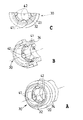
図16は、本発明の保護デバイス10の内側ケース30の他の実施形態を示し、ここでは内側ケース30が等しい4つの第1バルジ43(図ではそのうち3つのみが示されている)を具えている。これらは壁34の内面に形成され、内側空洞32内に張り出している。図16において、図10におけるものと同じ要素は同じ参照符号が付されている。図16の横平面P1に沿った内側ケース30の断面図である図15Bからさらに明らかなように、第1バルジ43は同じ横平面P1内に等間隔に配置され、水滴を半分にした形状を有している。その半水滴の最も広い部分は内側ケース30の遠位端30bに向いている。このバルジ43の特別な形状により、第1バルジ43の遠位面43aは内側ケース30の長手方向軸に対してほぼ30゜の角度αをなし、近位面43bは内側ケース30の長手方向軸に対してほぼ45゜の角度βをなしている。このため、ニードルハブ(不図示)に対する保護デバイス10の装着および取り外しが容易となる。
FIG. 16 shows another embodiment of the
図17は、図16の内側ケース30のさらに他の実施形態を示し、2つの第1バルジ43および4つの第2バルジ44を具えている。これらは壁34の内面に形成され、内側空洞32内に張り出している。第1バルジ43および第2バルジ44は、針アセンブリ(不図示)の一部に弾性的および解除可能に係合して、それに対する保護デバイス10の固定を行うことができるように設計される。図17において、図16におけるものと同じ要素は同じ参照符号が付されている。図17の横平面P1に沿った内側ケース30の断面図である図15Cからさらに明らかなように、第1バルジ43は径方向に互いに対向するように第1横平面P1内に配置され、周方向に不連続な突起を形成している。図17の横平面P2に沿った内側ケース30の断面図である図15Dからさらに明らかなように、第2バルジ44は第2横平面P2内に等間隔に配置されている。このように第1バルジ43および第2バルジ44を異なる横平面P1およびP2に配置することで、針ハブ6のより大きな部分に均等な保持力を分布させ、かつ、保護デバイス10の取り外しに要する力を増すことなく、針アセンブリに対し内側ケース30をより良好に維持できるようになる。
FIG. 17 shows still another embodiment of the
図18A〜図18Hは、図15A〜図15Dと同様な断面図であり、本発明の保護デバイス10の内側ケース30の他の実施形態を示し、これらにおいて第1バルジ43は所定の幾何学的形状をなしている。特に、
・図18Aにおいては、第1バルジ43が空洞32に長円形状の開口を形成し、
・図18B、図18Eおよび図18Gにおいては、第1バルジ43が空洞32に正方形に同等もしくはほぼ同等の開口を形成し、
・図18Cおよび図18Dにおいては、第1バルジ43が空洞32に三角形にほぼ同等の開口を形成し、
・図18Fにおいては、第1バルジ43が空洞32に星形にほぼ同等の開口を形成し、
・図18Hにおいては、第1バルジ43が空洞32に十字形にほぼ同等の開口を形成する、
ものとなっている。第2バルジ44についても、上述の所定の幾何学的形状の1つを形成するものとすることができる。
18A-18H are cross-sectional views similar to FIGS. 15A-15D showing other embodiments of the
In FIG. 18A, the
In FIG. 18B, FIG. 18E and FIG. 18G, the
18C and 18D, the
In FIG. 18F, the
In FIG. 18H, the
It has become a thing. The
図19〜図22は本発明の保護デバイス10の他の実施形態を示し、外側ケース20は、内側コア25と、その近位端にあるレリーフ構造26とを具えている。図1〜図9におけるものと同じ要素は同じ参照符号が付されている。内側コア25は、内側ケース30の材料に対する当接面を針プラグ36の近傍で提供する。図9および図22に示すように、針プラグ36は当接面24から距離Xをもって配置される近位方向を向く面38を有する。距離Xは、針(不図示)と当接面24との接触が生じることなく針を覆うに十分な大きさとされるが、保護デバイス10が針アセンブリ上に取り付けられときの内側ケース材の圧縮を低減する目的でその大きさが制限される。これは、針プラグ36に針を組み込む際の精度および信頼性を改善する。さらに、距離Xは、針プラグ36に必要な材料の量を低らし、これにより成形時の沈降(sinking)が低減される。この例においては、少なくとも0.5mmの針の先端と当接面24との間に距離Y(不図示)を残す目的で、距離Xは2、3mm(few milimeters)とされている。
19-22 show another embodiment of the
内側コア25の近位端に設けられるレリーフ構造(図21参照)は、内側ケースの材料のインジェクション過程でのリッジ22の潰れを防止する上で有利に働く。図19〜図22の保護デバイス10は、外側ケース20および内側ケース30の転位(transfer)を伴わずにコ・インジェクションを行うことによって製造することができる。あるいは、図19〜図22の保護デバイス10は、外側ケース20および内側ケース30の転位を伴ってコ・インジェクションを行うことによって製造することもできる。また、レリーフ構造26が存在することによって、空洞内の内側ケースの材料の量を低減することができ、これにより空洞の寸法安定性の向上を改善することができる。
The relief structure (see FIG. 21) provided at the proximal end of the
ここに記載され、説明され、特許が請求される本発明に係る保護デバイスは、従って、非常に低用量の薬液の注入(すなわち皮内注射)を目的とした注入デバイスまたはアセンブリの針の尖鋭性(sharpness)の保護および無菌性(sterility)の確保を可能とするものである。本発明の保護デバイスは、使用に先立ってこれが注入デバイスから取り外される際の、前記薬液用量の有意の部分が損失するリスクをなくすことができる。 The protective device according to the invention described, described and claimed is therefore a sharpness of the needle of the injection device or assembly intended for the injection of very low doses of drug solution (ie intradermal injection) (Sharpness) protection and sterility can be ensured. The protective device of the present invention can eliminate the risk of losing a significant portion of the drug dose when it is removed from the infusion device prior to use.
技術分野における当業者にとっては、ここに提供した開示から、本発明の範囲および精神から逸脱することなく種々の部分に関していくらかの代替および変形を行い得ることが自明であろう。例えば、注入デバイスの一例として注射器が説明されたが、明らかに本発明は、針が固定されまたは固定可能で、薬剤を患者に注入するのに使用される現在公知の、または今後開発されるいかなる注入デバイスにも向いたものである。 It will be apparent to those skilled in the art from the disclosure provided herein that some alternatives and modifications may be made with respect to the various parts without departing from the scope and spirit of the invention. For example, while a syringe has been described as an example of an infusion device, clearly the present invention can be applied to any currently known or later developed one in which the needle is fixed or fixable and used to inject a drug into a patient. Also suitable for injection devices.
Claims (15)
少なくとも1つの窓を有する外側ケースと、
該外側ケースと係合する内側ケースであって、少なくとも前記ハブ部を受容するよう構成された空洞を画成する内壁を有する内側ケースと、
該内側ケースを前記針アセンブリに対して取り外し可能に固定するために前記内側ケースの前記内壁から内方に突出し、前記針アセンブリと協働して少なくとも1つの封止線を形成する少なくとも1つの突起であって、該少なくとも1つの突起の少なくとも一部が前記外側ケースの前記少なくとも1つの窓と位置合わせされており、前記針アセンブリからの前記保護デバイスの取り外しに際して、前記ハブ部が前記少なくとも1つの突起と接触することで、前記少なくとも1つの窓に隣接した領域で前記内側ケースを半径方向外方に変形させる少なくとも1つの突起と、
を具え、
前記内側ケースが前記外側ケースに固定して係合することで、前記内側ケースおよび前記外側ケースが一体の部材として機能して、前記内側ケースの長手軸方向に沿った前記空洞の変形を制限するようにされていることを特徴とする保護デバイス。 A protective device for protecting said needle of a needle assembly including a hub portion for holding the needle,
An outer case having at least one window;
An inner case engaging the outer case, the inner case having an inner wall defining a cavity configured to receive at least the hub portion;
At least one protrusion projecting inwardly from the inner wall of the inner case for releasably securing the inner case to the needle assembly and cooperates with the needle assembly to form at least one sealing line. Wherein at least a portion of the at least one protrusion is aligned with the at least one window of the outer case and upon removal of the protection device from the needle assembly, the hub portion is the at least one At least one protrusion that deforms the inner case radially outward in a region adjacent to the at least one window by contacting the protrusion;
With
When the inner case is fixedly engaged with the outer case, the inner case and the outer case function as an integral member, and limit deformation of the cavity along the longitudinal axis direction of the inner case. A protective device characterized in that
Applications Claiming Priority (2)
| Application Number | Priority Date | Filing Date | Title |
|---|---|---|---|
| FR07/01530 | 2007-03-02 | ||
| FR0701530A FR2913200B1 (en) | 2007-03-02 | 2007-03-02 | NEEDLE PROTECTION DEVICE |
Related Parent Applications (1)
| Application Number | Title | Priority Date | Filing Date |
|---|---|---|---|
| JP2009552299A Division JP5576127B2 (en) | 2007-03-02 | 2008-03-03 | Needle protection device |
Related Child Applications (1)
| Application Number | Title | Priority Date | Filing Date |
|---|---|---|---|
| JP2016123671A Division JP6302005B2 (en) | 2007-03-02 | 2016-06-22 | Needle protection device |
Publications (2)
| Publication Number | Publication Date |
|---|---|
| JP2014176767A JP2014176767A (en) | 2014-09-25 |
| JP5960200B2 true JP5960200B2 (en) | 2016-08-02 |
Family
ID=38519868
Family Applications (4)
| Application Number | Title | Priority Date | Filing Date |
|---|---|---|---|
| JP2009552299A Active JP5576127B2 (en) | 2007-03-02 | 2008-03-03 | Needle protection device |
| JP2014137852A Active JP5960200B2 (en) | 2007-03-02 | 2014-07-03 | Needle protection device |
| JP2014137851A Active JP5905931B2 (en) | 2007-03-02 | 2014-07-03 | Needle protection device |
| JP2016123671A Active JP6302005B2 (en) | 2007-03-02 | 2016-06-22 | Needle protection device |
Family Applications Before (1)
| Application Number | Title | Priority Date | Filing Date |
|---|---|---|---|
| JP2009552299A Active JP5576127B2 (en) | 2007-03-02 | 2008-03-03 | Needle protection device |
Family Applications After (2)
| Application Number | Title | Priority Date | Filing Date |
|---|---|---|---|
| JP2014137851A Active JP5905931B2 (en) | 2007-03-02 | 2014-07-03 | Needle protection device |
| JP2016123671A Active JP6302005B2 (en) | 2007-03-02 | 2016-06-22 | Needle protection device |
Country Status (12)
| Country | Link |
|---|---|
| US (2) | US8672894B2 (en) |
| EP (2) | EP3492128B1 (en) |
| JP (4) | JP5576127B2 (en) |
| CN (1) | CN101663061B (en) |
| AU (1) | AU2008249725B2 (en) |
| BR (1) | BRPI0808204B8 (en) |
| CA (1) | CA2679595C (en) |
| ES (2) | ES2894862T3 (en) |
| FR (1) | FR2913200B1 (en) |
| MX (1) | MX2009009327A (en) |
| WO (1) | WO2008139330A2 (en) |
| ZA (1) | ZA200906275B (en) |
Families Citing this family (16)
| Publication number | Priority date | Publication date | Assignee | Title |
|---|---|---|---|---|
| DK2548597T3 (en) * | 2010-03-18 | 2016-11-07 | Daikyo Seiko Ltd | Syringe needle cover |
| WO2012023938A1 (en) | 2010-08-19 | 2012-02-23 | West Pharmaceutical Services, Inc. | Rigid needle shield |
| GB201021764D0 (en) * | 2010-12-22 | 2011-02-02 | Owen Mumford Ltd | Autoinjectors |
| FR2985669B1 (en) * | 2012-01-12 | 2015-10-02 | Biocorp Rech Et Dev | DEVICE FOR PROTECTING THE NEEDLE OF A SYRINGE |
| US10004854B2 (en) | 2012-03-07 | 2018-06-26 | West Pharmaceutical Services, Inc. | Low radial profile needle safety device |
| WO2013134465A1 (en) | 2012-03-07 | 2013-09-12 | West Pharmaceutical Services, Inc. | Low radial profile needle safety device |
| FR3002738B1 (en) * | 2013-03-01 | 2020-11-20 | Societe De Transf Des Elastomeres A Usages Medicaux Et Industriels | NEEDLE PROTECTION DEVICE. |
| WO2014141471A1 (en) * | 2013-03-15 | 2014-09-18 | テルモ株式会社 | Syringe assembly, syringe assembly packaging, and pre-filled syringe |
| FR3011473B1 (en) * | 2013-10-08 | 2015-12-18 | Aptar Stelmi Sas | PROTECTIVE DEVICE FOR SYRINGE NEEDLE. |
| EP2862587A1 (en) | 2013-10-15 | 2015-04-22 | Becton Dickinson France | Tip cap assembly for closing an injection system |
| US10179209B2 (en) * | 2014-02-11 | 2019-01-15 | Eli Lilly And Company | Injection needle covering system |
| JP1552665S (en) | 2014-05-08 | 2016-06-27 | ||
| FR3041263B1 (en) * | 2015-09-23 | 2017-11-24 | Aptar Stelmi Sas | DISPENSING ASSEMBLY COMPRISING A SYRINGE AND A NEEDLE PROTECTION DEVICE. |
| US11110228B2 (en) | 2015-11-27 | 2021-09-07 | Sanofi-Aventis Deutschland Gmbh | Component for an injection device, system, and method |
| USD818575S1 (en) * | 2015-12-08 | 2018-05-22 | Becton Dickinson France S.A.S. | Medical injector with enhanced grip |
| US20210379294A1 (en) * | 2018-10-26 | 2021-12-09 | Becton Dickinson France | Needle Cover for a Medical Injection Device |
Family Cites Families (13)
| Publication number | Priority date | Publication date | Assignee | Title |
|---|---|---|---|---|
| US3390759A (en) * | 1967-05-25 | 1968-07-02 | Becton Dickinson Co | Shield and hub for disposable needle |
| US4964866A (en) * | 1989-11-22 | 1990-10-23 | Becton, Dickinson And Company | Needle sheath assembly |
| US4986818A (en) * | 1990-03-30 | 1991-01-22 | Becton, Dickinson And Company | Syringe assembly |
| DE4234319A1 (en) * | 1992-10-12 | 1994-04-14 | Wimmer Pharma Gummi Gmbh | Process for producing a needle protection cap and needle protection cap for attaching or sliding onto a syringe needle |
| JPH08191893A (en) * | 1995-01-19 | 1996-07-30 | Arita Kouso Kagaku Kenkyusho:Kk | Injector with needle cover |
| US5858008A (en) | 1997-04-22 | 1999-01-12 | Becton, Dickinson And Company | Cannula sealing shield assembly |
| DE19717033A1 (en) * | 1997-04-23 | 1998-11-12 | Schott Glas | Needle cap for a prefillable disposable syringe |
| DE19954373B4 (en) * | 1999-11-11 | 2011-01-27 | Helvoet Pharma Belgium N.V. | Protective cap for a cannula |
| JP2001340457A (en) * | 2000-06-06 | 2001-12-11 | Hamiiru Cp:Kk | Replacement needle |
| FR2816848B1 (en) * | 2000-11-17 | 2003-06-20 | Rumpler Technologies | PROTECTION DEVICE FOR SYRINGE NEEDLE |
| EP1502616A1 (en) * | 2003-08-01 | 2005-02-02 | Bünder Glas GmbH | Needle protector for a glass syringe |
| JP2005152541A (en) * | 2003-11-21 | 2005-06-16 | Tasuku:Kk | Injection needle |
| DE102005058133A1 (en) * | 2005-11-30 | 2007-05-31 | Schott Ag | Syringe, has sealing element and syringe body whereby annular, flexible deformable area can be pressed in sealing manner, by means of closing cap, on outer surface of cannula |
-
2007
- 2007-03-02 FR FR0701530A patent/FR2913200B1/en active Active
-
2008
- 2008-03-03 BR BRPI0808204A patent/BRPI0808204B8/en active IP Right Grant
- 2008-03-03 AU AU2008249725A patent/AU2008249725B2/en active Active
- 2008-03-03 WO PCT/IB2008/002152 patent/WO2008139330A2/en active Application Filing
- 2008-03-03 ES ES19152702T patent/ES2894862T3/en active Active
- 2008-03-03 ES ES08356032T patent/ES2735975T3/en active Active
- 2008-03-03 JP JP2009552299A patent/JP5576127B2/en active Active
- 2008-03-03 CA CA2679595A patent/CA2679595C/en active Active
- 2008-03-03 CN CN2008800129284A patent/CN101663061B/en active Active
- 2008-03-03 EP EP19152702.7A patent/EP3492128B1/en active Active
- 2008-03-03 MX MX2009009327A patent/MX2009009327A/en active IP Right Grant
- 2008-03-03 EP EP08356032.6A patent/EP1964587B1/en active Active
- 2008-03-03 US US12/529,517 patent/US8672894B2/en active Active
-
2009
- 2009-09-09 ZA ZA200906275A patent/ZA200906275B/en unknown
-
2014
- 2014-01-27 US US14/164,643 patent/US9265895B2/en active Active
- 2014-07-03 JP JP2014137852A patent/JP5960200B2/en active Active
- 2014-07-03 JP JP2014137851A patent/JP5905931B2/en active Active
-
2016
- 2016-06-22 JP JP2016123671A patent/JP6302005B2/en active Active
Also Published As
| Publication number | Publication date |
|---|---|
| ES2894862T3 (en) | 2022-02-16 |
| EP1964587B1 (en) | 2019-05-01 |
| WO2008139330A3 (en) | 2009-04-30 |
| EP3492128B1 (en) | 2021-09-15 |
| EP1964587A1 (en) | 2008-09-03 |
| JP5905931B2 (en) | 2016-04-20 |
| JP2014176766A (en) | 2014-09-25 |
| CA2679595C (en) | 2015-05-05 |
| JP5576127B2 (en) | 2014-08-20 |
| AU2008249725A1 (en) | 2008-11-20 |
| US20140142513A1 (en) | 2014-05-22 |
| EP3492128A1 (en) | 2019-06-05 |
| WO2008139330A2 (en) | 2008-11-20 |
| JP2010520001A (en) | 2010-06-10 |
| CN101663061A (en) | 2010-03-03 |
| US20100198163A1 (en) | 2010-08-05 |
| FR2913200B1 (en) | 2009-12-11 |
| JP2014176767A (en) | 2014-09-25 |
| US9265895B2 (en) | 2016-02-23 |
| JP2016165617A (en) | 2016-09-15 |
| BRPI0808204B1 (en) | 2018-12-11 |
| MX2009009327A (en) | 2009-09-11 |
| US8672894B2 (en) | 2014-03-18 |
| ES2735975T3 (en) | 2019-12-23 |
| ZA200906275B (en) | 2010-04-28 |
| BRPI0808204B8 (en) | 2021-06-22 |
| AU2008249725B2 (en) | 2014-04-24 |
| FR2913200A1 (en) | 2008-09-05 |
| BRPI0808204A2 (en) | 2014-07-15 |
| CN101663061B (en) | 2013-05-22 |
| JP6302005B2 (en) | 2018-03-28 |
| CA2679595A1 (en) | 2008-11-20 |
Similar Documents
| Publication | Publication Date | Title |
|---|---|---|
| JP6302005B2 (en) | Needle protection device | |
| JP7004689B2 (en) | Syringe manufacturing method and syringe lock member | |
| US4128098A (en) | Valved spike transfer device | |
| EP0826385B1 (en) | Syringe assembly | |
| JP2008229328A (en) | Shield for covering front edge of administration device or assembly unit, administration assembly unit and administration device | |
| JP2008307369A (en) | Shield for covering extremity of administration device or assembly, its assembly and administration device | |
| US20030187401A1 (en) | Syringe with integral safety system | |
| US20060079848A1 (en) | Non-skin penetrating reconstituting syringe | |
| JPH0613054B2 (en) | Injection injector | |
| JPH0747125A (en) | Lure needle unit and syringe | |
| ZA200409474B (en) | Safety injectors | |
| JP4883877B2 (en) | Intradermal needle | |
| AU2014206160B2 (en) | Protection device for a needle | |
| CA2872144C (en) | Sheath protecting a cannula, and safety syringe comprising said sheath | |
| EP2844320B1 (en) | Sheath protecting a cannula, and safety syringe comprising said sheath |
Legal Events
| Date | Code | Title | Description |
|---|---|---|---|
| A621 | Written request for application examination |
Free format text: JAPANESE INTERMEDIATE CODE: A621 Effective date: 20140729 |
|
| A977 | Report on retrieval |
Free format text: JAPANESE INTERMEDIATE CODE: A971007 Effective date: 20150501 |
|
| A131 | Notification of reasons for refusal |
Free format text: JAPANESE INTERMEDIATE CODE: A131 Effective date: 20150512 |
|
| A601 | Written request for extension of time |
Free format text: JAPANESE INTERMEDIATE CODE: A601 Effective date: 20150812 |
|
| A521 | Request for written amendment filed |
Free format text: JAPANESE INTERMEDIATE CODE: A523 Effective date: 20150911 |
|
| A131 | Notification of reasons for refusal |
Free format text: JAPANESE INTERMEDIATE CODE: A131 Effective date: 20151215 |
|
| A521 | Request for written amendment filed |
Free format text: JAPANESE INTERMEDIATE CODE: A523 Effective date: 20160315 |
|
| TRDD | Decision of grant or rejection written | ||
| A01 | Written decision to grant a patent or to grant a registration (utility model) |
Free format text: JAPANESE INTERMEDIATE CODE: A01 Effective date: 20160524 |
|
| A61 | First payment of annual fees (during grant procedure) |
Free format text: JAPANESE INTERMEDIATE CODE: A61 Effective date: 20160622 |
|
| R150 | Certificate of patent or registration of utility model |
Ref document number: 5960200 Country of ref document: JP Free format text: JAPANESE INTERMEDIATE CODE: R150 |
|
| R250 | Receipt of annual fees |
Free format text: JAPANESE INTERMEDIATE CODE: R250 |
|
| R250 | Receipt of annual fees |
Free format text: JAPANESE INTERMEDIATE CODE: R250 |
|
| R250 | Receipt of annual fees |
Free format text: JAPANESE INTERMEDIATE CODE: R250 |
|
| R250 | Receipt of annual fees |
Free format text: JAPANESE INTERMEDIATE CODE: R250 |