JP5958552B2 - Control device for hybrid vehicle - Google Patents
Control device for hybrid vehicle Download PDFInfo
- Publication number
- JP5958552B2 JP5958552B2 JP2014548524A JP2014548524A JP5958552B2 JP 5958552 B2 JP5958552 B2 JP 5958552B2 JP 2014548524 A JP2014548524 A JP 2014548524A JP 2014548524 A JP2014548524 A JP 2014548524A JP 5958552 B2 JP5958552 B2 JP 5958552B2
- Authority
- JP
- Japan
- Prior art keywords
- vehicle
- information
- mode
- hybrid vehicle
- section
- Prior art date
- Legal status (The legal status is an assumption and is not a legal conclusion. Google has not performed a legal analysis and makes no representation as to the accuracy of the status listed.)
- Active
Links
Images


Classifications
-
- B—PERFORMING OPERATIONS; TRANSPORTING
- B60—VEHICLES IN GENERAL
- B60K—ARRANGEMENT OR MOUNTING OF PROPULSION UNITS OR OF TRANSMISSIONS IN VEHICLES; ARRANGEMENT OR MOUNTING OF PLURAL DIVERSE PRIME-MOVERS IN VEHICLES; AUXILIARY DRIVES FOR VEHICLES; INSTRUMENTATION OR DASHBOARDS FOR VEHICLES; ARRANGEMENTS IN CONNECTION WITH COOLING, AIR INTAKE, GAS EXHAUST OR FUEL SUPPLY OF PROPULSION UNITS IN VEHICLES
- B60K6/00—Arrangement or mounting of plural diverse prime-movers for mutual or common propulsion, e.g. hybrid propulsion systems comprising electric motors and internal combustion engines
- B60K6/20—Arrangement or mounting of plural diverse prime-movers for mutual or common propulsion, e.g. hybrid propulsion systems comprising electric motors and internal combustion engines the prime-movers consisting of electric motors and internal combustion engines, e.g. HEVs
- B60K6/50—Architecture of the driveline characterised by arrangement or kind of transmission units
- B60K6/54—Transmission for changing ratio
- B60K6/547—Transmission for changing ratio the transmission being a stepped gearing
-
- B—PERFORMING OPERATIONS; TRANSPORTING
- B60—VEHICLES IN GENERAL
- B60K—ARRANGEMENT OR MOUNTING OF PROPULSION UNITS OR OF TRANSMISSIONS IN VEHICLES; ARRANGEMENT OR MOUNTING OF PLURAL DIVERSE PRIME-MOVERS IN VEHICLES; AUXILIARY DRIVES FOR VEHICLES; INSTRUMENTATION OR DASHBOARDS FOR VEHICLES; ARRANGEMENTS IN CONNECTION WITH COOLING, AIR INTAKE, GAS EXHAUST OR FUEL SUPPLY OF PROPULSION UNITS IN VEHICLES
- B60K6/00—Arrangement or mounting of plural diverse prime-movers for mutual or common propulsion, e.g. hybrid propulsion systems comprising electric motors and internal combustion engines
- B60K6/20—Arrangement or mounting of plural diverse prime-movers for mutual or common propulsion, e.g. hybrid propulsion systems comprising electric motors and internal combustion engines the prime-movers consisting of electric motors and internal combustion engines, e.g. HEVs
- B60K6/42—Arrangement or mounting of plural diverse prime-movers for mutual or common propulsion, e.g. hybrid propulsion systems comprising electric motors and internal combustion engines the prime-movers consisting of electric motors and internal combustion engines, e.g. HEVs characterised by the architecture of the hybrid electric vehicle
- B60K6/48—Parallel type
-
- B—PERFORMING OPERATIONS; TRANSPORTING
- B60—VEHICLES IN GENERAL
- B60L—PROPULSION OF ELECTRICALLY-PROPELLED VEHICLES; SUPPLYING ELECTRIC POWER FOR AUXILIARY EQUIPMENT OF ELECTRICALLY-PROPELLED VEHICLES; ELECTRODYNAMIC BRAKE SYSTEMS FOR VEHICLES IN GENERAL; MAGNETIC SUSPENSION OR LEVITATION FOR VEHICLES; MONITORING OPERATING VARIABLES OF ELECTRICALLY-PROPELLED VEHICLES; ELECTRIC SAFETY DEVICES FOR ELECTRICALLY-PROPELLED VEHICLES
- B60L15/00—Methods, circuits, or devices for controlling the traction-motor speed of electrically-propelled vehicles
- B60L15/20—Methods, circuits, or devices for controlling the traction-motor speed of electrically-propelled vehicles for control of the vehicle or its driving motor to achieve a desired performance, e.g. speed, torque, programmed variation of speed
- B60L15/2045—Methods, circuits, or devices for controlling the traction-motor speed of electrically-propelled vehicles for control of the vehicle or its driving motor to achieve a desired performance, e.g. speed, torque, programmed variation of speed for optimising the use of energy
-
- B—PERFORMING OPERATIONS; TRANSPORTING
- B60—VEHICLES IN GENERAL
- B60L—PROPULSION OF ELECTRICALLY-PROPELLED VEHICLES; SUPPLYING ELECTRIC POWER FOR AUXILIARY EQUIPMENT OF ELECTRICALLY-PROPELLED VEHICLES; ELECTRODYNAMIC BRAKE SYSTEMS FOR VEHICLES IN GENERAL; MAGNETIC SUSPENSION OR LEVITATION FOR VEHICLES; MONITORING OPERATING VARIABLES OF ELECTRICALLY-PROPELLED VEHICLES; ELECTRIC SAFETY DEVICES FOR ELECTRICALLY-PROPELLED VEHICLES
- B60L50/00—Electric propulsion with power supplied within the vehicle
- B60L50/10—Electric propulsion with power supplied within the vehicle using propulsion power supplied by engine-driven generators, e.g. generators driven by combustion engines
- B60L50/16—Electric propulsion with power supplied within the vehicle using propulsion power supplied by engine-driven generators, e.g. generators driven by combustion engines with provision for separate direct mechanical propulsion
-
- B—PERFORMING OPERATIONS; TRANSPORTING
- B60—VEHICLES IN GENERAL
- B60L—PROPULSION OF ELECTRICALLY-PROPELLED VEHICLES; SUPPLYING ELECTRIC POWER FOR AUXILIARY EQUIPMENT OF ELECTRICALLY-PROPELLED VEHICLES; ELECTRODYNAMIC BRAKE SYSTEMS FOR VEHICLES IN GENERAL; MAGNETIC SUSPENSION OR LEVITATION FOR VEHICLES; MONITORING OPERATING VARIABLES OF ELECTRICALLY-PROPELLED VEHICLES; ELECTRIC SAFETY DEVICES FOR ELECTRICALLY-PROPELLED VEHICLES
- B60L58/00—Methods or circuit arrangements for monitoring or controlling batteries or fuel cells, specially adapted for electric vehicles
- B60L58/10—Methods or circuit arrangements for monitoring or controlling batteries or fuel cells, specially adapted for electric vehicles for monitoring or controlling batteries
- B60L58/12—Methods or circuit arrangements for monitoring or controlling batteries or fuel cells, specially adapted for electric vehicles for monitoring or controlling batteries responding to state of charge [SoC]
-
- B—PERFORMING OPERATIONS; TRANSPORTING
- B60—VEHICLES IN GENERAL
- B60W—CONJOINT CONTROL OF VEHICLE SUB-UNITS OF DIFFERENT TYPE OR DIFFERENT FUNCTION; CONTROL SYSTEMS SPECIALLY ADAPTED FOR HYBRID VEHICLES; ROAD VEHICLE DRIVE CONTROL SYSTEMS FOR PURPOSES NOT RELATED TO THE CONTROL OF A PARTICULAR SUB-UNIT
- B60W20/00—Control systems specially adapted for hybrid vehicles
- B60W20/10—Controlling the power contribution of each of the prime movers to meet required power demand
- B60W20/12—Controlling the power contribution of each of the prime movers to meet required power demand using control strategies taking into account route information
-
- G—PHYSICS
- G01—MEASURING; TESTING
- G01C—MEASURING DISTANCES, LEVELS OR BEARINGS; SURVEYING; NAVIGATION; GYROSCOPIC INSTRUMENTS; PHOTOGRAMMETRY OR VIDEOGRAMMETRY
- G01C21/00—Navigation; Navigational instruments not provided for in groups G01C1/00 - G01C19/00
- G01C21/26—Navigation; Navigational instruments not provided for in groups G01C1/00 - G01C19/00 specially adapted for navigation in a road network
- G01C21/34—Route searching; Route guidance
- G01C21/3453—Special cost functions, i.e. other than distance or default speed limit of road segments
- G01C21/3469—Fuel consumption; Energy use; Emission aspects
-
- G—PHYSICS
- G08—SIGNALLING
- G08G—TRAFFIC CONTROL SYSTEMS
- G08G1/00—Traffic control systems for road vehicles
- G08G1/01—Detecting movement of traffic to be counted or controlled
- G08G1/0104—Measuring and analyzing of parameters relative to traffic conditions
- G08G1/0108—Measuring and analyzing of parameters relative to traffic conditions based on the source of data
- G08G1/0112—Measuring and analyzing of parameters relative to traffic conditions based on the source of data from the vehicle, e.g. floating car data [FCD]
-
- G—PHYSICS
- G08—SIGNALLING
- G08G—TRAFFIC CONTROL SYSTEMS
- G08G1/00—Traffic control systems for road vehicles
- G08G1/01—Detecting movement of traffic to be counted or controlled
- G08G1/0104—Measuring and analyzing of parameters relative to traffic conditions
- G08G1/0125—Traffic data processing
- G08G1/0129—Traffic data processing for creating historical data or processing based on historical data
-
- G—PHYSICS
- G08—SIGNALLING
- G08G—TRAFFIC CONTROL SYSTEMS
- G08G1/00—Traffic control systems for road vehicles
- G08G1/01—Detecting movement of traffic to be counted or controlled
- G08G1/0104—Measuring and analyzing of parameters relative to traffic conditions
- G08G1/0137—Measuring and analyzing of parameters relative to traffic conditions for specific applications
- G08G1/0141—Measuring and analyzing of parameters relative to traffic conditions for specific applications for traffic information dissemination
-
- B—PERFORMING OPERATIONS; TRANSPORTING
- B60—VEHICLES IN GENERAL
- B60L—PROPULSION OF ELECTRICALLY-PROPELLED VEHICLES; SUPPLYING ELECTRIC POWER FOR AUXILIARY EQUIPMENT OF ELECTRICALLY-PROPELLED VEHICLES; ELECTRODYNAMIC BRAKE SYSTEMS FOR VEHICLES IN GENERAL; MAGNETIC SUSPENSION OR LEVITATION FOR VEHICLES; MONITORING OPERATING VARIABLES OF ELECTRICALLY-PROPELLED VEHICLES; ELECTRIC SAFETY DEVICES FOR ELECTRICALLY-PROPELLED VEHICLES
- B60L2240/00—Control parameters of input or output; Target parameters
- B60L2240/60—Navigation input
- B60L2240/62—Vehicle position
- B60L2240/622—Vehicle position by satellite navigation
-
- B—PERFORMING OPERATIONS; TRANSPORTING
- B60—VEHICLES IN GENERAL
- B60L—PROPULSION OF ELECTRICALLY-PROPELLED VEHICLES; SUPPLYING ELECTRIC POWER FOR AUXILIARY EQUIPMENT OF ELECTRICALLY-PROPELLED VEHICLES; ELECTRODYNAMIC BRAKE SYSTEMS FOR VEHICLES IN GENERAL; MAGNETIC SUSPENSION OR LEVITATION FOR VEHICLES; MONITORING OPERATING VARIABLES OF ELECTRICALLY-PROPELLED VEHICLES; ELECTRIC SAFETY DEVICES FOR ELECTRICALLY-PROPELLED VEHICLES
- B60L2240/00—Control parameters of input or output; Target parameters
- B60L2240/60—Navigation input
- B60L2240/68—Traffic data
-
- B—PERFORMING OPERATIONS; TRANSPORTING
- B60—VEHICLES IN GENERAL
- B60L—PROPULSION OF ELECTRICALLY-PROPELLED VEHICLES; SUPPLYING ELECTRIC POWER FOR AUXILIARY EQUIPMENT OF ELECTRICALLY-PROPELLED VEHICLES; ELECTRODYNAMIC BRAKE SYSTEMS FOR VEHICLES IN GENERAL; MAGNETIC SUSPENSION OR LEVITATION FOR VEHICLES; MONITORING OPERATING VARIABLES OF ELECTRICALLY-PROPELLED VEHICLES; ELECTRIC SAFETY DEVICES FOR ELECTRICALLY-PROPELLED VEHICLES
- B60L2240/00—Control parameters of input or output; Target parameters
- B60L2240/70—Interactions with external data bases, e.g. traffic centres
-
- B—PERFORMING OPERATIONS; TRANSPORTING
- B60—VEHICLES IN GENERAL
- B60L—PROPULSION OF ELECTRICALLY-PROPELLED VEHICLES; SUPPLYING ELECTRIC POWER FOR AUXILIARY EQUIPMENT OF ELECTRICALLY-PROPELLED VEHICLES; ELECTRODYNAMIC BRAKE SYSTEMS FOR VEHICLES IN GENERAL; MAGNETIC SUSPENSION OR LEVITATION FOR VEHICLES; MONITORING OPERATING VARIABLES OF ELECTRICALLY-PROPELLED VEHICLES; ELECTRIC SAFETY DEVICES FOR ELECTRICALLY-PROPELLED VEHICLES
- B60L2250/00—Driver interactions
- B60L2250/16—Driver interactions by display
-
- B—PERFORMING OPERATIONS; TRANSPORTING
- B60—VEHICLES IN GENERAL
- B60L—PROPULSION OF ELECTRICALLY-PROPELLED VEHICLES; SUPPLYING ELECTRIC POWER FOR AUXILIARY EQUIPMENT OF ELECTRICALLY-PROPELLED VEHICLES; ELECTRODYNAMIC BRAKE SYSTEMS FOR VEHICLES IN GENERAL; MAGNETIC SUSPENSION OR LEVITATION FOR VEHICLES; MONITORING OPERATING VARIABLES OF ELECTRICALLY-PROPELLED VEHICLES; ELECTRIC SAFETY DEVICES FOR ELECTRICALLY-PROPELLED VEHICLES
- B60L2260/00—Operating Modes
- B60L2260/40—Control modes
- B60L2260/50—Control modes by future state prediction
- B60L2260/52—Control modes by future state prediction drive range estimation, e.g. of estimation of available travel distance
-
- B—PERFORMING OPERATIONS; TRANSPORTING
- B60—VEHICLES IN GENERAL
- B60L—PROPULSION OF ELECTRICALLY-PROPELLED VEHICLES; SUPPLYING ELECTRIC POWER FOR AUXILIARY EQUIPMENT OF ELECTRICALLY-PROPELLED VEHICLES; ELECTRODYNAMIC BRAKE SYSTEMS FOR VEHICLES IN GENERAL; MAGNETIC SUSPENSION OR LEVITATION FOR VEHICLES; MONITORING OPERATING VARIABLES OF ELECTRICALLY-PROPELLED VEHICLES; ELECTRIC SAFETY DEVICES FOR ELECTRICALLY-PROPELLED VEHICLES
- B60L2260/00—Operating Modes
- B60L2260/40—Control modes
- B60L2260/50—Control modes by future state prediction
- B60L2260/54—Energy consumption estimation
-
- B—PERFORMING OPERATIONS; TRANSPORTING
- B60—VEHICLES IN GENERAL
- B60W—CONJOINT CONTROL OF VEHICLE SUB-UNITS OF DIFFERENT TYPE OR DIFFERENT FUNCTION; CONTROL SYSTEMS SPECIALLY ADAPTED FOR HYBRID VEHICLES; ROAD VEHICLE DRIVE CONTROL SYSTEMS FOR PURPOSES NOT RELATED TO THE CONTROL OF A PARTICULAR SUB-UNIT
- B60W2556/00—Input parameters relating to data
- B60W2556/45—External transmission of data to or from the vehicle
- B60W2556/50—External transmission of data to or from the vehicle of positioning data, e.g. GPS [Global Positioning System] data
-
- B—PERFORMING OPERATIONS; TRANSPORTING
- B60—VEHICLES IN GENERAL
- B60W—CONJOINT CONTROL OF VEHICLE SUB-UNITS OF DIFFERENT TYPE OR DIFFERENT FUNCTION; CONTROL SYSTEMS SPECIALLY ADAPTED FOR HYBRID VEHICLES; ROAD VEHICLE DRIVE CONTROL SYSTEMS FOR PURPOSES NOT RELATED TO THE CONTROL OF A PARTICULAR SUB-UNIT
- B60W2556/00—Input parameters relating to data
- B60W2556/45—External transmission of data to or from the vehicle
- B60W2556/65—Data transmitted between vehicles
-
- Y—GENERAL TAGGING OF NEW TECHNOLOGICAL DEVELOPMENTS; GENERAL TAGGING OF CROSS-SECTIONAL TECHNOLOGIES SPANNING OVER SEVERAL SECTIONS OF THE IPC; TECHNICAL SUBJECTS COVERED BY FORMER USPC CROSS-REFERENCE ART COLLECTIONS [XRACs] AND DIGESTS
- Y02—TECHNOLOGIES OR APPLICATIONS FOR MITIGATION OR ADAPTATION AGAINST CLIMATE CHANGE
- Y02T—CLIMATE CHANGE MITIGATION TECHNOLOGIES RELATED TO TRANSPORTATION
- Y02T10/00—Road transport of goods or passengers
- Y02T10/60—Other road transportation technologies with climate change mitigation effect
- Y02T10/62—Hybrid vehicles
-
- Y—GENERAL TAGGING OF NEW TECHNOLOGICAL DEVELOPMENTS; GENERAL TAGGING OF CROSS-SECTIONAL TECHNOLOGIES SPANNING OVER SEVERAL SECTIONS OF THE IPC; TECHNICAL SUBJECTS COVERED BY FORMER USPC CROSS-REFERENCE ART COLLECTIONS [XRACs] AND DIGESTS
- Y02—TECHNOLOGIES OR APPLICATIONS FOR MITIGATION OR ADAPTATION AGAINST CLIMATE CHANGE
- Y02T—CLIMATE CHANGE MITIGATION TECHNOLOGIES RELATED TO TRANSPORTATION
- Y02T10/00—Road transport of goods or passengers
- Y02T10/60—Other road transportation technologies with climate change mitigation effect
- Y02T10/64—Electric machine technologies in electromobility
-
- Y—GENERAL TAGGING OF NEW TECHNOLOGICAL DEVELOPMENTS; GENERAL TAGGING OF CROSS-SECTIONAL TECHNOLOGIES SPANNING OVER SEVERAL SECTIONS OF THE IPC; TECHNICAL SUBJECTS COVERED BY FORMER USPC CROSS-REFERENCE ART COLLECTIONS [XRACs] AND DIGESTS
- Y02—TECHNOLOGIES OR APPLICATIONS FOR MITIGATION OR ADAPTATION AGAINST CLIMATE CHANGE
- Y02T—CLIMATE CHANGE MITIGATION TECHNOLOGIES RELATED TO TRANSPORTATION
- Y02T10/00—Road transport of goods or passengers
- Y02T10/60—Other road transportation technologies with climate change mitigation effect
- Y02T10/70—Energy storage systems for electromobility, e.g. batteries
-
- Y—GENERAL TAGGING OF NEW TECHNOLOGICAL DEVELOPMENTS; GENERAL TAGGING OF CROSS-SECTIONAL TECHNOLOGIES SPANNING OVER SEVERAL SECTIONS OF THE IPC; TECHNICAL SUBJECTS COVERED BY FORMER USPC CROSS-REFERENCE ART COLLECTIONS [XRACs] AND DIGESTS
- Y02—TECHNOLOGIES OR APPLICATIONS FOR MITIGATION OR ADAPTATION AGAINST CLIMATE CHANGE
- Y02T—CLIMATE CHANGE MITIGATION TECHNOLOGIES RELATED TO TRANSPORTATION
- Y02T10/00—Road transport of goods or passengers
- Y02T10/60—Other road transportation technologies with climate change mitigation effect
- Y02T10/7072—Electromobility specific charging systems or methods for batteries, ultracapacitors, supercapacitors or double-layer capacitors
-
- Y—GENERAL TAGGING OF NEW TECHNOLOGICAL DEVELOPMENTS; GENERAL TAGGING OF CROSS-SECTIONAL TECHNOLOGIES SPANNING OVER SEVERAL SECTIONS OF THE IPC; TECHNICAL SUBJECTS COVERED BY FORMER USPC CROSS-REFERENCE ART COLLECTIONS [XRACs] AND DIGESTS
- Y02—TECHNOLOGIES OR APPLICATIONS FOR MITIGATION OR ADAPTATION AGAINST CLIMATE CHANGE
- Y02T—CLIMATE CHANGE MITIGATION TECHNOLOGIES RELATED TO TRANSPORTATION
- Y02T10/00—Road transport of goods or passengers
- Y02T10/60—Other road transportation technologies with climate change mitigation effect
- Y02T10/72—Electric energy management in electromobility
-
- Y—GENERAL TAGGING OF NEW TECHNOLOGICAL DEVELOPMENTS; GENERAL TAGGING OF CROSS-SECTIONAL TECHNOLOGIES SPANNING OVER SEVERAL SECTIONS OF THE IPC; TECHNICAL SUBJECTS COVERED BY FORMER USPC CROSS-REFERENCE ART COLLECTIONS [XRACs] AND DIGESTS
- Y02—TECHNOLOGIES OR APPLICATIONS FOR MITIGATION OR ADAPTATION AGAINST CLIMATE CHANGE
- Y02T—CLIMATE CHANGE MITIGATION TECHNOLOGIES RELATED TO TRANSPORTATION
- Y02T90/00—Enabling technologies or technologies with a potential or indirect contribution to GHG emissions mitigation
- Y02T90/10—Technologies relating to charging of electric vehicles
- Y02T90/16—Information or communication technologies improving the operation of electric vehicles
Landscapes
- Engineering & Computer Science (AREA)
- Transportation (AREA)
- Mechanical Engineering (AREA)
- Chemical & Material Sciences (AREA)
- Power Engineering (AREA)
- Physics & Mathematics (AREA)
- General Physics & Mathematics (AREA)
- Analytical Chemistry (AREA)
- Combustion & Propulsion (AREA)
- Radar, Positioning & Navigation (AREA)
- Remote Sensing (AREA)
- Automation & Control Theory (AREA)
- Life Sciences & Earth Sciences (AREA)
- Sustainable Development (AREA)
- Sustainable Energy (AREA)
- Hybrid Electric Vehicles (AREA)
- Electric Propulsion And Braking For Vehicles (AREA)
Description
本発明は、走行駆動源にエンジン及びモータを備え、モータのみの駆動力で走行する電気自動車モードと、エンジン及びモータの駆動力で走行するハイブリッド車モードとを選択可能なハイブリッド車両の制御装置に関する発明である。 The present invention relates to a control apparatus for a hybrid vehicle that includes an engine and a motor in a travel drive source, and can select an electric vehicle mode that travels using only the motor and a hybrid vehicle mode that travels using the drive force of the engine and motor It is an invention.
従来、走行駆動源にガソリン等の燃料を使用して駆動するエンジンと、バッテリを電力源として駆動するモータを有するハイブリッド車両に搭載され、予め設定された予定走行経路上の混雑状況や車速情報を考慮して、バッテリの充放電制御を行うハイブリッド車両の制御装置が知られている(例えば、特許文献1参照)。 Conventionally, it is mounted on a hybrid vehicle having an engine driven using fuel such as gasoline as a travel drive source and a motor driven by using a battery as an electric power source. In consideration of this, a control device for a hybrid vehicle that performs charge / discharge control of a battery is known (see, for example, Patent Document 1).
しかしながら、従来のハイブリッド車両の制御装置では、予定走行経路上の混雑状況や車速情報は、対象となる予定走行経路を走行したすべての他車両の統計データに基づいて決定される。すなわち、従来のハイブリッド車両の制御装置では、予定走行経路における統計データに、自車両とは車両タイプや排気量等の車両の属性が全く異なる情報も含まれている。
そのため、この統計データを利用して走行モードのスケジューリングを行ってしまうと、自車両の走行状況にマッチせず、適切な走行モードのスケジューリングを行うことが難しかった。そして、走行モードのスケジューリングが自車両の走行状況に合わないため、エンジンの燃料消費量を抑制しきれず、燃費向上を図ることが難しいという問題があった。However, in the conventional hybrid vehicle control device, the congestion status and vehicle speed information on the planned travel route are determined based on statistical data of all other vehicles that have traveled on the planned planned travel route. That is, in the conventional hybrid vehicle control device, the statistical data on the planned travel route includes information that is completely different from the own vehicle such as the vehicle type and the displacement such as the displacement.
Therefore, if running mode scheduling is performed using this statistical data, it does not match the running situation of the host vehicle, and it is difficult to schedule an appropriate running mode. And since scheduling of driving modes does not match the driving conditions of the host vehicle, there is a problem that it is difficult to improve fuel consumption because the fuel consumption of the engine cannot be suppressed.
本発明は、上記問題に着目してなされたもので、予定走行経路における他車両の車両情報を利用して走行モードのスケジューリングを行う際に、適切なスケジューリングを行うことで燃費向上を図ることができるハイブリッド車両の制御装置を提供することを目的とする。 The present invention has been made paying attention to the above-mentioned problem, and when performing scheduling of a driving mode using vehicle information of other vehicles on a planned driving route, it is possible to improve fuel efficiency by performing appropriate scheduling. An object of the present invention is to provide a control device for a hybrid vehicle.
上記目的を達成するため、本発明のハイブリッド車両の制御装置は、走行駆動源としてエンジン及びモータを備え、走行モードとして、前記エンジンを停止させると共に前記モータのみを走行駆動源とする電気自動車モードと、前記エンジンと前記モータの双方を走行駆動源とするハイブリッド車モードとを選択可能なハイブリッド車両に搭載され、ナビゲーターと、情報取得部と、車両制御部と、を備える。
前記ナビゲーターは、自車両の現在地から目的地までの予定走行経路を設定する。
前記情報取得部は、前記予定走行経路を走行した他車両の情報から、自車両の属性に対応する情報を取得する。
前記車両制御部は、前記情報取得部によって取得された選別情報に基づいて、前記予定走行経路での走行モードのスケジューリングを行う。In order to achieve the above object, a control apparatus for a hybrid vehicle of the present invention includes an engine and a motor as a travel drive source, and the travel mode is an electric vehicle mode in which the engine is stopped and only the motor is a travel drive source. The vehicle is mounted on a hybrid vehicle that can select a hybrid vehicle mode that uses both the engine and the motor as a travel drive source, and includes a navigator, an information acquisition unit, and a vehicle control unit.
The navigator sets a planned travel route from the current location of the host vehicle to the destination.
The said information acquisition part acquires the information corresponding to the attribute of the own vehicle from the information of the other vehicle which drive | worked the said scheduled driving | running route.
The vehicle control unit schedules a travel mode on the planned travel route based on the selection information acquired by the information acquisition unit.
本発明のハイブリッド車両の制御装置では、情報取得部により、ナビゲーターによって設定された予定走行経路を走行した他車両の情報から、自車両の属性に対応する車両情報が選別して取得される。そして、車両制御部により、取得された選別情報に基づいて、予定走行経路での走行モードのスケジューリングが行われる。
すなわち、走行モードのスケジューリングを行う際に参照する情報を選別取得することで、例えば全車両平均の情報を参照してスケジューリングする場合よりも、自車両の走行状況に合わせた走行モードのスケジューリングを行うことができる。そのため、モータを効率的に利用することができ、エンジンの燃料消費量を適切に抑制して、燃費向上を図ることできる。In the hybrid vehicle control device of the present invention, the information acquisition unit selects and acquires the vehicle information corresponding to the attribute of the host vehicle from the information of the other vehicle that has traveled on the planned travel route set by the navigator. Then, based on the acquired selection information, the vehicle control unit schedules the travel mode on the planned travel route.
In other words, by selecting and acquiring information to be referred to when scheduling of the driving mode, for example, scheduling of the driving mode according to the driving situation of the host vehicle is performed rather than scheduling with reference to the average information of all vehicles. be able to. Therefore, the motor can be used efficiently, and fuel consumption of the engine can be appropriately suppressed to improve fuel efficiency.
以下、本発明のハイブリッド車両の制御装置を実施するための形態を、図面に示す実施例1及び実施例2に基づいて説明する。 EMBODIMENT OF THE INVENTION Hereinafter, the form for implementing the control apparatus of the hybrid vehicle of this invention is demonstrated based on Example 1 and Example 2 which are shown in drawing.
(実施例1)
まず、実施例1のハイブリッド車両の制御装置の構成を、「ハイブリッド車両の全体システム構成」、「車両制御システムの構成」、「車両制御処理の構成」に分けて説明する。Example 1
First, the configuration of the hybrid vehicle control device according to the first embodiment will be described by dividing it into “the overall system configuration of the hybrid vehicle”, “the configuration of the vehicle control system”, and “the configuration of the vehicle control process”.
[ハイブリッド車両の全体システム構成]
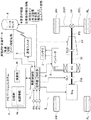
図1は、実施例1のハイブリッド車両の制御装置が適用されたハイブリッド車両を示す全体システム図である。以下、図1に基づき、実施例1のハイブリッド車両の全体システム構成を説明する。[Overall system configuration of hybrid vehicle]
FIG. 1 is an overall system diagram illustrating a hybrid vehicle to which the hybrid vehicle control device of the first embodiment is applied. The overall system configuration of the hybrid vehicle according to the first embodiment will be described below with reference to FIG.
実施例1におけるハイブリッド車両Sは、後輪駆動によるFRハイブリッド車両(ハイブリッド車両の一例)である。このFRハイブリッド車両Sの駆動系は、図1に示すように、エンジンEngと、第1クラッチCL1と、モータ/ジェネレータMGと、第2クラッチCL2と、自動変速機ATと、変速機入力軸INと、プロペラシャフトPSと、ディファレンシャルDFと、左ドライブシャフトDSLと、右ドライブシャフトDSRと、左後輪RL(駆動輪)と、右後輪RR(駆動輪)と、を有する。なお、FLは左前輪、FRは右前輪である。 The hybrid vehicle S in the first embodiment is a rear-wheel drive FR hybrid vehicle (an example of a hybrid vehicle). As shown in FIG. 1, the drive system of the FR hybrid vehicle S includes an engine Eng, a first clutch CL1, a motor / generator MG, a second clutch CL2, an automatic transmission AT, and a transmission input shaft IN. A propeller shaft PS, a differential DF, a left drive shaft DSL, a right drive shaft DSR, a left rear wheel RL (drive wheel), and a right rear wheel RR (drive wheel). Note that FL is the left front wheel and FR is the right front wheel.
前記エンジンEngは、ガソリンエンジンやディーゼルエンジンであり、車両制御部1からのエンジン制御指令に基づいて、エンジン始動制御やエンジン停止制御やスロットルバルブのバルブ開度制御やフューエルカット制御等が行われる。なお、エンジン出力軸には、フライホイールFWを介して第1クラッチCL1が接続されている。
The engine Eng is a gasoline engine or a diesel engine, and engine start control, engine stop control, throttle valve opening control, fuel cut control, and the like are performed based on an engine control command from the
前記第1クラッチCL1は、前記エンジンEngとモータ/ジェネレータMGの間に介装されたクラッチであり、車両制御部1からの制御指令に基づいて図示しない油圧ユニットにより作り出された第1クラッチ制御油圧により、締結・スリップ締結・開放が制御される。この第1クラッチCL1としては、例えば、ダイアフラムスプリングによる付勢力にて完全締結を保ち、ピストンを有する油圧アクチュエータを用いたストローク制御により、完全締結〜スリップ締結〜完全開放までが制御されるノーマルクローズの乾式単板クラッチが用いられる。なお、この第1クラッチCL1は、モータ/ジェネレータMGのみを走行駆動源とする電気自動車モードと、エンジンEngとモータ/ジェネレータMGの双方を走行駆動源とするハイブリッド車モードと、を切り替えるモード切り替え機構となっている。
The first clutch CL1 is a clutch interposed between the engine Eng and the motor / generator MG, and a first clutch control hydraulic pressure generated by a hydraulic unit (not shown) based on a control command from the
前記モータ/ジェネレータMGは、ロータに永久磁石を埋設しステータにステータコイルが巻き付けられた同期型モータ/ジェネレータであり、車両制御部1からの制御指令に基づいて、インバータ2により作り出された三相交流を印加することにより制御される。このモータ/ジェネレータMGは、バッテリ3からの電力の供給を受けて回転駆動し、エンジンEngの始動や左右後輪RL,RRの駆動を行う電動機として動作することもできる(以下、この動作状態を「力行」という)し、ロータがエンジンEngや左右後輪RL,RRから回転エネルギーを受ける場合には、ステータコイルの両端に起電力を生じさせる発電機として機能し、バッテリ3を充電することもできる(以下、この動作状態を「回生」という)。なお、このモータ/ジェネレータMGのロータは、自動変速機ATの変速機入力軸INに連結されている。
The motor / generator MG is a synchronous motor / generator in which a permanent magnet is embedded in a rotor and a stator coil is wound around a stator, and the three-phase generated by the
前記第2クラッチCL2は、前記モータ/ジェネレータMGと左右後輪RL,RRの間に介装されたクラッチであり、車両制御部1からの制御指令に基づいて図示しない油圧ユニットにより作り出された第2クラッチ制御油圧により、締結・スリップ締結・開放が制御される。
この第2クラッチCL2としては、例えば、比例ソレノイドで油流量および油圧を連続的に制御できるノーマルオープンの湿式多板クラッチや湿式多板ブレーキが用いられる。The second clutch CL2 is a clutch interposed between the motor / generator MG and the left and right rear wheels RL, RR, and is generated by a hydraulic unit (not shown) based on a control command from the
As the second clutch CL2, for example, a normally open wet multi-plate clutch or a wet multi-plate brake capable of continuously controlling the oil flow rate and hydraulic pressure with a proportional solenoid is used.
前記自動変速機ATは、モータ/ジェネレータMGと左右後輪RL,RRの間に介装され、例えば、前進7速/後退1速等の有段階の変速段を車速やアクセル開度等に応じて自動的に切り替える有段変速機である。この自動変速機ATの変速機出力軸には、プロペラシャフトPSが連結されている。そして、このプロペラシャフトPSは、ディファレンシャルDF、左ドライブシャフトDSL、右ドライブシャフトDSRを介して左右後輪RL,RRに連結されている。
なお、実施例1では、自動変速機ATの各変速段にて締結される複数の摩擦締結要素のうち、トルク伝達経路に配置されると共に所定の条件に適合する最適な摩擦係合要素(クラッチやブレーキ)を選択し、第2クラッチCL2としている。すなわち、前記第2クラッチCL2は、自動変速機ATとは独立の専用クラッチとして新たに追加したものではない。The automatic transmission AT is interposed between the motor / generator MG and the left and right rear wheels RL and RR. For example, the automatic transmission AT can change a stepped gear stage such as forward 7 speed /
In the first embodiment, among a plurality of frictional engagement elements that are engaged at each gear stage of the automatic transmission AT, an optimum frictional engagement element (clutch that is disposed on the torque transmission path and that meets a predetermined condition) Or the brake) is selected and the second clutch CL2 is selected. That is, the second clutch CL2 is not newly added as a dedicated clutch independent of the automatic transmission AT.
そして、このFRハイブリッド車両Sは、駆動形態の違い、つまり走行駆動源の違いによる走行モードとして、電気自動車モード(以下、「EVモード」という)と、ハイブリッド車モード(以下、「HEVモード」という)と、を有する。 The FR hybrid vehicle S has an electric vehicle mode (hereinafter referred to as “EV mode”) and a hybrid vehicle mode (hereinafter referred to as “HEV mode”) as a driving mode depending on a driving mode, that is, a driving drive source. And).
前記「EVモード」は、第1クラッチCL1を開放状態とし、エンジンEngを停止してモータ/ジェネレータMGの駆動力のみで走行するモードである。この「EVモード」は、モータ走行モード・回生走行モードを有する。この「EVモード」は、要求駆動トルクが低く、バッテリ3の充電残量(以下、「バッテリSOC(State Of Chargeの略)」という)が確保されているときに選択される。 The “EV mode” is a mode in which the first clutch CL1 is released, the engine Eng is stopped, and the vehicle travels only with the driving force of the motor / generator MG. The “EV mode” has a motor travel mode and a regenerative travel mode. This “EV mode” is selected when the required drive torque is low and the remaining charge of the battery 3 (hereinafter referred to as “battery SOC (abbreviation of State Of Charge)”) is secured.
前記「HEVモード」は、第1クラッチCL1を締結状態とし、エンジンEngとモータ/ジェネレータMGの双方の駆動力で走行するモードである。この「HEVモード」は、モータアシスト走行モード・発電走行モード・エンジン走行モード・を有する。この「HEVモード」は、要求駆動トルクが高いとき、あるいは、バッテリSOCが不足するようなときに選択される。 The “HEV mode” is a mode in which the first clutch CL1 is engaged and the vehicle travels with the driving forces of both the engine Eng and the motor / generator MG. The “HEV mode” has a motor assist travel mode, a power generation travel mode, and an engine travel mode. The “HEV mode” is selected when the required drive torque is high or when the battery SOC is insufficient.
[車両制御システムの構成]
実施例1におけるFRハイブリッド車両Sの車両制御システムは、図1に示すように、車両制御部1と、インバータ2と、バッテリ3と、ナビゲーションシステム(ナビゲーター)4と、通信ユニット5と、を有して構成されている。[Configuration of vehicle control system]
As shown in FIG. 1, the vehicle control system of the FR hybrid vehicle S according to the first embodiment includes a
前記車両制御部1は、本発明における車両の制御装置であり、複数のCPUを有するマイクロコンピュータとその周辺部品や各種アクチュエータなどを備え、エンジンEngの回転速度や出力トルク、第1クラッチCL1,第2クラッチCL2の締結・スリップ締結・開放、モータ/ジェネレータMGの回転速度や出力トルク、自動変速機ATの変速段などを制御する。また、この車両制御部1は、取得部1aと、制御部1bと、を有している。
前記取得部1aは、車両制御部1が有するCPUの一つによって構成され、データセンタ8から、自車両の属性に合致する車両情報を取得する情報取得部に相当する。
前記制御部1bは、車両制御部1が有するCPUの一つによって構成され、後述する車両制御処理を実行し、FRハイブリッド車両Sの予定走行経路での走行モードをスケジューリングする車両制御部に相当する。
さらに、この車両制御部1には、車速センサ6Aからの車速情報や、バッテリSOCを常時監視するSOC監視部6BからのバッテリSOC情報、バッテリ3の電流消費を抑制するエコモードへの移行指示を入力するエコスイッチ6CからのスイッチON/OFF情報が入力される。The
The
The
Further, the
前記ナビゲーションシステム4は、記憶部4aと、演算部4bと、ディスプレイ(不図示)と、を有している。前記記憶部4aは、道路曲率半径、勾配、交差点、信号、踏み切り、横断歩道、制限速度、料金所等の道路環境情報や、道路属性情報(高速道路・幹線道路・一般道・住宅街等)を含む地図情報を記憶するメモリである。前記演算部4bは、衛星からの信号を受信し、このFRハイブリッド車両Sの地球上の絶対位置を検出する演算回路である。この演算部4bでは、記憶部4aに記憶されている地図を参照し、現在FRハブリッド車両Sが存在している位置(現在地)を特定すると共に、この現在地から目的地までの予定走行経路を設定する。この予定走行経路及びその経路上の道路環状情報・道路属性情報は、車両制御部1に入力される。また、不図示のディスプレイは、車室内に設けられ、ドライバーから目視可能となっている。
The
前記通信ユニット5は、車両制御部1に接続されると共に、図示しない無線基地局及びインターネット等の通信ネットワークを介して、交通情報や統計交通データを有するデータセンタ8との無線通信(テレマティクス通信)を行う。この「通信」は双方向であり、通信ユニット5を介して、車両制御部1の取得部1aからデータセンタ8へと情報を送信することや、通信ユニット5を介して、データセンタ8から情報を受信して車両制御部1の取得部1aへ入力することが可能である。
なお、前記通信ユニット5としては、携帯電話機、DSRC、無線LANなど様々なものを採用することができる。また、この通信ユニット5を介して取得部1aへ入力された情報は、必要に応じてナビゲーションシステム4に入力される。The
As the
[車両制御処理の構成]
図2は、実施例1の車両制御部にて実行される車両制御処理の流れを示すフローチャートである。以下、車両制御処理内容を示す図2のフローチャートの各ステップについて説明する。[Configuration of vehicle control processing]
FIG. 2 is a flowchart illustrating a flow of a vehicle control process executed by the vehicle control unit according to the first embodiment. Hereinafter, each step of the flowchart of FIG. 2 showing the contents of the vehicle control process will be described.
ステップS1では、ナビゲーションシステム4により現在地から目的地までの予定走行経路を設定し、ステップS2へ移行する。
ここで、この予定走行経路の設定は、まず、ドライバーが手動操作によってナビゲーションシステム4に目的地を入力する。そして、ナビゲーションシステム4では、入力された目的地情報と、衛星からの信号に基づいて検出した現在地情報と、記憶部4aに記憶された地図情報に基づいて複数の走行経路を検索し、車室内に設けられたディスプレイに表示する。そして、ドライバーは検索された走行経路から予定走行経路を選択して設定する。
なお、設定された予定走行経路は、通信ユニット5を介してデータセンタ8へと送信される。In step S1, a planned travel route from the current location to the destination is set by the
Here, in setting the planned travel route, first, the driver inputs a destination to the
The set scheduled travel route is transmitted to the
ステップS2では、ステップS1での予定走行経路の設定に続き、車両制御部1の取得部1aから通信ユニット5を介して、データセンタ8に自車両の属性情報を送信し、ステップS3へ移行する。
ここで、「自車両の属性情報」とは、このFRハイブリッド車両についての車両情報であり、取得部1aに予め設定されている。「属性」の項目としては、ここでは、車両のタイプ(SUV:Sport Utility Vehicle・セダン・スポーツセダン・2輪車等)、車両重量、排気量、駆動方式(電気自動車・ハイブリッド自動車・エンジン自動車/内燃機関自動車・燃料電池車等)、エコスイッチ状態(スイッチON・スイッチOFF)である。In step S2, following the setting of the planned travel route in step S1, attribute information of the host vehicle is transmitted from the
Here, the “own vehicle attribute information” is vehicle information about the FR hybrid vehicle, and is preset in the
ステップS3では、ステップS2での自車両情報の送信に続き、取得部1aは、通信ユニット5を介してデータセンタ8から予定走行経路上の統計交通データ、つまり他車両の情報を取得し、ステップS4へ移行する。
このとき、データセンタ8では、取得部1aから送信された属性に合致する統計交通データ(車両情報)を選別し、選別した統計交通データのみを送信する。ここで、「統計交通データ」とは、データセンタ8において設定されたノードと呼ばれる道路上の基準位置間隔ごとに決められた車速、加速度、勾配である。なお、「勾配」については自車両の属性に無関係であり、地図情報に基づいて送信される。In step S3, following the transmission of the host vehicle information in step S2, the
At this time, the
ステップS4では、ステップS3での統計交通データの取得に続き、設定された予定走行経路を複数の区間に分割すると共に、分割した各区間における区間車速、区間加速度、区間勾配を選択取得した統計交通データから演算し、ステップS5へ移行する。
なお、この経路の分割は、FRハイブリッド車両Sが取得可能な経路分割に必要な様々なLINK情報に基づいて設定される分割基準位置によって、図3に示すように、現在地から目的地までの予定走行経路を予め設定した数(ここではn)に分割することで行う。In step S4, following the acquisition of the statistical traffic data in step S3, the set planned travel route is divided into a plurality of sections, and the section traffic speed, the section acceleration, and the section gradient in each divided section are selected and acquired. Calculation is performed from the data, and the process proceeds to step S5.
This route division is scheduled from the current location to the destination as shown in FIG. 3 according to the division reference positions set based on various LINK information necessary for route division that can be acquired by the FR hybrid vehicle S. This is done by dividing the travel route into a predetermined number (here n).
ステップS5では、ステップS4での走行経路の分割に続き、予定走行経路を複数に分割して設定された各区間(n=1〜n=n)のそれぞれの区間の区間EV係数を演算し、ステップS6へ移行する。
ここで、「EV係数」とは、ある区間をモータ/ジェネレータMGのみの動力で走行した場合の電力消費量と、同じ区間をエンジンEngのみの動力で走行した場合の燃料消費量との比である。
そして、区間EV係数を求めるには、まず、図4に示すように、予め設定された車両情報に基づき、モータ/ジェネレータMGのみの動力で走行したときの要求駆動力に対する電力消費量を示す電力消費量マップと、エンジンEngのみの動力で走行したときの要求駆動力に対する燃料消費量を示す燃料消費量マップを設定する。次に、この電力消費量マップ及び燃料消費量マップと、対象区間の区間車速と、対象区間の区間加速度と、対象区間の区間勾配に基づき、対象区間をモータ/ジェネレータMGのみの動力で走行したときの区間要求駆動力に対する電力消費量(区間電力消費量)と、対象区間をエンジンEngのみの動力で走行したときの区間要求駆動力に対する燃料消費量(区間燃料消費量)をそれぞれ求める。そして、区間燃料消費量を区間電力消費量で除算し、対象区間におけるEV係数(区間EV係数)を求める。
なお、「車両情報」とは、例えば、車重・空気抵抗係数・車両前面投影面積・転がり抵抗係数・モータ効率・エンジン効率・変速機効率等である。
また、「区間要求駆動力」とは、対象区間における要求駆動力である。この区間要求駆動力は、ステップS4にて算出された対象区間の区間車速・区間加速度・区間勾配によって決定される。In step S5, following the division of the travel route in step S4, the section EV coefficient of each section of each section (n = 1 to n = n) set by dividing the planned travel route into a plurality is calculated, The process proceeds to step S6.
Here, the “EV coefficient” is the ratio between the power consumption when traveling in a section with the power of only the motor / generator MG and the fuel consumption when traveling in the same section with the power of only the engine Eng. is there.
Then, in order to obtain the section EV coefficient, first, as shown in FIG. 4, based on preset vehicle information, electric power indicating the power consumption with respect to the required driving force when traveling with the power of only the motor / generator MG. A consumption map and a fuel consumption map indicating the fuel consumption with respect to the required driving force when traveling with the power of only the engine Eng are set. Next, based on the power consumption map and fuel consumption map, the section vehicle speed of the target section, the section acceleration of the target section, and the section gradient of the target section, the target section was driven with the power of the motor / generator MG alone. The power consumption (section power consumption) with respect to the required section driving force at the time and the fuel consumption (section fuel consumption) with respect to the section required driving power when the target section is driven by the power of only the engine Eng are obtained. Then, the section fuel consumption is divided by the section power consumption to obtain the EV coefficient (section EV coefficient) in the target section.
The “vehicle information” includes, for example, vehicle weight, air resistance coefficient, vehicle front projected area, rolling resistance coefficient, motor efficiency, engine efficiency, transmission efficiency, and the like.
The “section required driving force” is the required driving force in the target section. This section required driving force is determined by the section vehicle speed, section acceleration, and section gradient of the target section calculated in step S4.
ステップS6では、ステップS5での区間EV係数の演算に続き、予定走行経路を複数に分割して設定された各区間における予定走行モードを設定し、ステップS7へ移行する。
ここで、「予定走行モード」とは、対象区間における目標走行モードである。この予定走行モードの設定は、ステップS6にて演算した区間EV係数に基づいて行う。すなわち、区間EVモードが1以上となった区間では、予定走行モードを「EVモード」に設定する。
一方、区間EVモードが1未満となった区間では、この区間EV係数が大きい順に予定走行モードを「EVモード」に設定する。そして、予定走行モードが「EVモード」に設定された区間の区間電力消費量の積算値が、予め設定されているバッテリ3の使用可能限界量に達したら、「EVモード」の設定(割り当て)を終了する。そして、残りの区間は、予定走行モードを「HEVモード」に設定する。
なお、実施例1では、ステップS1からステップS6までを走行前、つまり予定走行経路設定時に実行する。In step S6, following the calculation of the section EV coefficient in step S5, the planned travel mode in each section set by dividing the planned travel route into a plurality of sections is set, and the process proceeds to step S7.
Here, the “scheduled travel mode” is a target travel mode in the target section. The scheduled travel mode is set based on the section EV coefficient calculated in step S6. That is, in the section in which the section EV mode is 1 or more, the planned travel mode is set to “EV mode”.
On the other hand, in the section in which the section EV mode is less than 1, the scheduled travel mode is set to “EV mode” in descending order of the section EV coefficient. Then, when the integrated value of the section power consumption of the section in which the planned traveling mode is set to “EV mode” reaches the preset usable limit amount of the
In the first embodiment, steps S1 to S6 are executed before traveling, that is, when a planned traveling route is set.
ステップS7では、ステップS6での予定走行モードの設定に続き、実際の走行中におけるMG最大出力値(以下、「現在のMG最大出力値」という)を演算し、ステップS8へ移行する。
ここで、「MG最大出力値」は、バッテリSOCに応じて決められる現時点のモータ/ジェネレータMGの最大出力値である。このMG最大出力値の設定は、現在走行中の区間の予定走行モードが「EVモード」に設定されている場合と、「HEVモード」に設定されている場合で異なる。
すなわち、図5に示すように、予定走行モードが「EVモード」に設定されている区間では、バッテリSOCに対してMG最大出力値を一義的に決める初期MG最大出力値設定マップと、SOC監視部7から入力された現在のSOC情報(図5では「SOC_now」と示す)に基づき、現在のMG最大出力値を求める。つまり、予定走行モードが「EVモード」に設定されている区間では、モータ/ジェネレータMGの最大出力値が許す限り、走行駆動源としてモータ/ジェネレータMGを利用する。
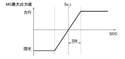
一方、予定走行モードが「HEVモード」に設定されている区間では、図5に示すように、まず、SOC監視部7から入力された現在のSOC情報(図5では「SOC_now」と示す)と、初期MG最大出力値設定マップにおいてモータ出力がゼロになるときのSOC情報である初期SOC中心(図6では「Sc_i」と示す)と、に応じて、MG最大出力値設定マップのシフト量を演算する。なお、このシフト量の演算は、下記式(1)により行う。
シフト量=SOC_now−Sc_i ・・・(1)
次に、初期MG最大出力値設定マップに上記シフト量を加算し、初期MG最大出力値設定マップのZ線をシフトする。これにより、この初期MG最大出力値設定マップにおけるSOC中心、及び、初期MG最大出力値設定マップにおいてモータ出力がゼロになってから最大出力になるまでのSOC幅(図6では「SW」と示す)が変更され、新たなMG最大出力設定値マップが設定される。そして、この新たに設定されたMG最大出力値設定マップと、SOC監視部7から入力された現在のSOC情報(図5では「SOC_now」と示す)に基づき、現在のMG最大出力値を求める。つまり、予定走行モードが「HEVモード」に設定されている区間では、バッテリSOCが多く残っていても、できるだけバッテリSOCを減らさないように走行駆動源としてエンジンEngも利用する。In step S7, following the setting of the planned travel mode in step S6, an MG maximum output value during actual travel (hereinafter referred to as “current MG maximum output value”) is calculated, and the process proceeds to step S8.
Here, “MG maximum output value” is the current maximum output value of motor / generator MG determined in accordance with battery SOC. The setting of the MG maximum output value differs depending on whether the planned travel mode of the currently traveling section is set to “EV mode” or “HEV mode”.
That is, as shown in FIG. 5, in the section in which the planned travel mode is set to “EV mode”, an initial MG maximum output value setting map that uniquely determines the MG maximum output value for the battery SOC, and the SOC monitoring Based on the current SOC information (shown as “SOC_now” in FIG. 5) input from the
On the other hand, in the section where the planned travel mode is set to “HEV mode”, as shown in FIG. 5, first, the current SOC information (shown as “SOC_now” in FIG. 5) input from the
Shift amount = SOC_now−Sc_i (1)
Next, the shift amount is added to the initial MG maximum output value setting map, and the Z line of the initial MG maximum output value setting map is shifted. Thereby, the SOC center in this initial MG maximum output value setting map and the SOC width (shown as “SW” in FIG. 6) from when the motor output becomes zero to the maximum output in the initial MG maximum output value setting map. ) Is changed, and a new MG maximum output set value map is set. Then, based on the newly set MG maximum output value setting map and the current SOC information (indicated as “SOC_now” in FIG. 5) input from the
ステップS8では、ステップS7での現在のMG最大出力値の演算に続き、実際に走行しているときの走行モード(以下、「実際の走行モード」という)の設定を行い、ステップS9へ移行する。
ここで、実際の走行モードを設定するには、図7に示すように、まず、現在のアクセル開度、車速、路面勾配から要求駆動力を求める。そして、ステップS7にて求めた現在のMG最大出力値と上記要求駆動力を比較する。そして、現在のMG最大出力値が要求駆動力よりも小さいときには、モータ/ジェネレータMGのみの駆動力では要求駆動力を賄えないとして、エンジン起動フラグが1になり(True=1)、エンジンEngが起動して「HEVモード」となる。また、現在のMG最大出力値が要求駆動力よりも大きいときには、モータ/ジェネレータMGのみの駆動力で要求駆動力を賄えるとして、エンジン起動フラグがゼロになり(False=0)、エンジンEngは停止して「EVモード」となる。In step S8, following the calculation of the current MG maximum output value in step S7, a travel mode for actual travel (hereinafter referred to as “actual travel mode”) is set, and the process proceeds to step S9. .
Here, in order to set the actual travel mode, as shown in FIG. 7, first, the required driving force is obtained from the current accelerator opening, vehicle speed, and road surface gradient. Then, the current MG maximum output value obtained in step S7 is compared with the required driving force. When the current maximum MG output value is smaller than the required driving force, the driving force of only the motor / generator MG cannot cover the required driving force, the engine start flag becomes 1 (True = 1), and the engine Eng Starts up and enters “HEV mode”. In addition, when the current maximum MG output value is larger than the required driving force, the engine starting flag becomes zero (False = 0) and the engine Eng is stopped, assuming that the driving force of only the motor / generator MG can cover the required driving force. It becomes "EV mode".
ステップS9では、ステップS8での実際の走行モードの設定に続き、ハイブリッド車両が目的地に到達したか否かを判断する。YES(目的に到着)の場合には、エンドへ移行し、この車両制御処理を終了する。NO(目的地に未到着)の場合には、ステップS7へ戻る。
ここで、目的地に到着したか否かの判断は、ナビゲーションシステム4によって、衛星からの信号に基づいて検出した現在地情報から判断する。
なお、実施例1では、ステップS7からステップS9までを走行中に実行する。In step S9, following the setting of the actual travel mode in step S8, it is determined whether or not the hybrid vehicle has reached the destination. In the case of YES (arriving at the purpose), the process proceeds to the end, and this vehicle control process is terminated. If NO (no arrival at the destination), the process returns to step S7.
Here, whether or not the destination has been reached is determined from the current location information detected by the
In the first embodiment, steps S7 to S9 are executed during traveling.
次に、実施例1のハイブリッド車両の制御装置における車両制御作用を説明する。 Next, the vehicle control action in the hybrid vehicle control apparatus of the first embodiment will be described.
[車両制御作用]
図8は、比較例の車両制御装置での車両制御時の取得車速情報・予定走行モード・バッテリSOCと、実施例1の車両制御装置での車両制御時の取得車両情報・予定走行モード・バッテリSOCを示すタイムチャートである。以下、図8に基づき、実施例1のハイブリッド車両の制御装置における車両制御作用を説明する。[Vehicle control action]
FIG. 8 shows acquired vehicle speed information / scheduled travel mode / battery SOC at the time of vehicle control by the vehicle control device of the comparative example, and acquired vehicle information / scheduled travel mode / battery at the time of vehicle control by the vehicle control device of the first embodiment. It is a time chart which shows SOC. Hereinafter, based on FIG. 8, the vehicle control action in the hybrid vehicle control apparatus of the first embodiment will be described.
比較例の車両制御装置において、予定走行モードを設定するには、まず、ナビゲーションシステムによって予定走行経路を設定する。続いて、データセンタと通信を行い、設定された予定走行経路上の統計交通データのうち、車速に関するデータを取得する。このとき、データセンタに蓄積されている全車両の平均車速を車速データとして取得する。そして、設定された予定走行経路を複数の区間に分割すると共に、分割した各区間における区間車速を取得した統計交通データから演算する。 In the vehicle control device of the comparative example, in order to set the planned travel mode, first, the planned travel route is set by the navigation system. Subsequently, communication with the data center is performed, and data relating to the vehicle speed is acquired from the statistical traffic data on the set scheduled travel route. At this time, the average vehicle speed of all the vehicles accumulated in the data center is acquired as vehicle speed data. Then, the set planned traveling route is divided into a plurality of sections, and the section vehicle speed in each divided section is calculated from the acquired statistical traffic data.
そして、区間ごとに演算した区間車速に基づいて、予定走行経路を分割して設定された各区間の予定走行モードを決める。ここで、予定走行モードは、例えば、所定の車速を基準に設定する。すなわち、車速が予め設定した閾値(図8において「EV-HEV切替閾値」という)よりも低い場合には、予定走行モードを「EVモード」に設定する。そして、車速がこのEV-HEV切替閾値以上の場合では、予定走行モードを「HEVモード」に設定する。 Then, based on the section vehicle speed calculated for each section, the planned travel mode of each section set by dividing the planned travel route is determined. Here, the planned travel mode is set based on a predetermined vehicle speed, for example. That is, when the vehicle speed is lower than a preset threshold value (referred to as “EV-HEV switching threshold value” in FIG. 8), the scheduled travel mode is set to “EV mode”. When the vehicle speed is equal to or higher than the EV-HEV switching threshold, the planned travel mode is set to “HEV mode”.
これにより、この比較例のハイブリッド車両の制御装置では、図8に示す区間n1において、区間車速がEV-HEV切替閾値を下回っているため、この区間n1では、予定走行モードが「EVモード」に設定される。また、図8に示す区間n2〜n3において、区間車速がEV-HEV切替閾値を上回っているため、この区間n2〜n3では、予定走行モードが「HEVモード」に設定される。さらに、図8に示す区間n4では、区間車速が再びEV-HEV切替閾値を下回っているため、この区間n4では、予定走行モードが「EVモード」に設定される。そして、図8に示す区間n5では、区間車速がEV-HEV切替閾値を再度上回っているため、この区間n5では、予定走行モードが「HEVモード」に設定される。 As a result, in the hybrid vehicle control device of this comparative example, the section vehicle speed is lower than the EV-HEV switching threshold value in the section n1 shown in FIG. Is set. Further, in the sections n2 to n3 shown in FIG. 8, the section vehicle speed exceeds the EV-HEV switching threshold value, and therefore, in the sections n2 to n3, the planned travel mode is set to “HEV mode”. Further, in the section n4 shown in FIG. 8, the section vehicle speed is again lower than the EV-HEV switching threshold, and therefore, in this section n4, the planned travel mode is set to “EV mode”. In section n5 shown in FIG. 8, the section vehicle speed again exceeds the EV-HEV switching threshold, and therefore, in this section n5, the scheduled travel mode is set to “HEV mode”.
これに対し、実施例1の車両制御装置で走行モードの制御処理を実行するには、まず、図2に示すフローチャートにおいて、ステップS1の予定走行経路の設定をナビゲーションシステム4によって行う。続いて、ステップS2へと進み、データセンタ8へ自車両情報を送信する。そして、ステップS3へと進んでデータセンタ8から統計交通データを取得する。
On the other hand, in order to execute the driving mode control process by the vehicle control apparatus of the first embodiment, first, the
このとき、データセンタ8では、FRハブリッド車両Sから送られてきた自車両情報、すなわちFRハイブリッド車両Sの属性を参照し、この属性に合致した車両に関する統計交通データ(ここでは、車速、加速度)を選別する。そして、この選別した統計交通データを出力する。
これにより、車両制御部1では、自車両の属性に合致した他車両の統計交通データを取得する。At this time, the
Thereby, the
そして、ステップS4に進んで、予定走行経路を複数の区間に分割した後、ステップS5→ステップS6へと進んで、各区間のEV係数を求めると共に、その区間EV係数に基づいて各区間の予定走行モードを設定する。 Then, the process proceeds to step S4, and after dividing the planned travel route into a plurality of sections, the process proceeds from step S5 to step S6 to obtain the EV coefficient of each section, and the schedule of each section is determined based on the section EV coefficient. Set the driving mode.
このとき、図8に示す区間n5では、区間車速が比較例のハイブリッド車両の制御装置で取得した区間車速よりも大幅に低くなっている。そのため、ここでは図示しないが区間EV係数が高くなり、この区間n5では予定走行モードが「EVモード」に設定される。 At this time, in the section n5 shown in FIG. 8, the section vehicle speed is significantly lower than the section vehicle speed acquired by the hybrid vehicle control device of the comparative example. Therefore, although not shown here, the section EV coefficient becomes high, and the planned travel mode is set to “EV mode” in this section n5.
そして、この実施例1のハイブリッド車両の制御装置において、ステップS6で各区間の予定走行モードを設定したら、ステップS7→ステップS8へと進み、現在のSOC情報に基づいて現在のMG最大出力値を求めると共に、実際の走行モードを設定する。 In the hybrid vehicle control apparatus according to the first embodiment, when the planned travel mode of each section is set in step S6, the process proceeds from step S7 to step S8, and the current MG maximum output value is determined based on the current SOC information. At the same time, set the actual driving mode.
このとき、図8に示す区間n4を走行し終わった時点(時刻t時点)では、バッテリSOCは比較的残っている。一方、走行中の区間の予定走行モードが「EVモード」のときには、初期MG最大出力値設定マップがシフトされないため、バッテリSOCは比較的高ければ、MG最大出力値が大きくなり、実際の走行モードも「EVモード」に設定されやすくなる。そして、実際の走行モードが「EVモード」に設定されれば、エンジンEngを駆動することなく走行することができ、総燃料消費量を削減することができる。 At this time, the battery SOC remains relatively at the time when the vehicle has traveled in the section n4 shown in FIG. 8 (time t). On the other hand, when the planned travel mode of the section being traveled is “EV mode”, the initial MG maximum output value setting map is not shifted. Therefore, if the battery SOC is relatively high, the MG maximum output value increases and the actual travel mode Will be easily set to "EV mode". If the actual travel mode is set to “EV mode”, the vehicle can travel without driving the engine Eng, and the total fuel consumption can be reduced.
しかしながら、比較例のハイブリッド車両の制御装置のように、図8に示す区間n5において、予定走行モードを「HEVモード」に設定してしまうと、初期MG最大出力値設定マップがシフトされてしまう。そのため、図8に示す区間n4を走行し終わった時点(時刻t時点)においてバッテリSOCが比較的残っていても、MG最大出力値が低くなってしまい、実際の走行モードも「HEVモード」に設定されやすくなる。そして、実際の走行モードが「HEVモード」に設定されれば、エンジンEngを駆動して走行することになり、バッテリSOCを適切に利用することができずに、実施例1と比較して総燃料消費量を削減しきれなくなってしまう。 However, if the planned travel mode is set to the “HEV mode” in the section n5 shown in FIG. 8 as in the control device for the hybrid vehicle of the comparative example, the initial MG maximum output value setting map is shifted. For this reason, even when the battery SOC remains relatively at the end of traveling in the section n4 shown in FIG. 8 (time t), the MG maximum output value becomes low, and the actual traveling mode is also changed to the “HEV mode”. It becomes easy to set. If the actual travel mode is set to “HEV mode”, the engine Eng is driven to travel, and the battery SOC cannot be used appropriately. It becomes impossible to reduce fuel consumption.
特に、実施例1のハイブリッド車両の制御装置では、予定走行モードを設定する際に必要となる区間EV係数を演算する際に、区間車速と、区間加速度と、区間勾配から区間要求駆動力を求めている。そのため、区間EV係数の演算精度を、例えば区間車速のみに基づいて区間駆動力を求める場合よりも向上することができる。
これにより、走行モードの設定をより最適なものとすることができ、さらにバッテリSOCを適切に利用することができて、燃費向上を図ることができる。In particular, in the hybrid vehicle control apparatus according to the first embodiment, when the section EV coefficient necessary for setting the planned travel mode is calculated, the section required driving force is obtained from the section vehicle speed, the section acceleration, and the section gradient. ing. Therefore, the calculation accuracy of the section EV coefficient can be improved as compared with the case where the section driving force is obtained based only on the section vehicle speed, for example.
As a result, the travel mode can be set more optimally, and the battery SOC can be used appropriately, thereby improving fuel consumption.
そして、実施例1のハイブリッド車両の制御装置では、自車両の属性にエコスイッチ状態が含まれている。つまり、FRハブリッド車両Sのエコスイッチの状態に合致する他車両の情報を取得するようになっている。
これにより、より自車両の状態に近い情報に基づいて走行モードのスケジューリングを行うことができるため、走行モードの設定をより最適なものとすることができ、さらに燃費向上を図ることができる。And in the control apparatus of the hybrid vehicle of Example 1, the eco switch state is included in the attribute of the own vehicle. That is, the information of the other vehicle that matches the state of the eco switch of the FR hybrid vehicle S is acquired.
Thereby, since the driving mode can be scheduled based on information closer to the state of the host vehicle, the setting of the driving mode can be made more optimal, and fuel efficiency can be further improved.
次に、効果を説明する。
実施例1のハイブリッド車両の制御装置にあっては、下記に列挙する効果を得ることができる。Next, the effect will be described.
In the hybrid vehicle control device of the first embodiment, the following effects can be obtained.
(1) 走行駆動源としてエンジンEng及びモータ/ジェネレータ(モータ)MGを備え、走行モードとして、前記エンジンEngを停止させると共に前記モータ/ジェネレータ(モータ)MGのみを走行駆動源とする電気自動車モード(EVモード)と、前記エンジンEngと前記モータ/ジェネレータ(モータ)MGの双方を走行駆動源とするハイブリッド車モード(HEVモード)とを選択可能なFRハイブリッド車両Sに搭載され、
自車両の現在地から目的地までの予定走行経路を設定するナビゲーションシステム(ナビゲーター)4と、
前記予定走行経路を走行した車両の統計交通データ(他車両の車両情報)から、自車両の属性に合致する(対応する)車両情報を取得する取得部(情報取得部)1aと、
前記取得部(情報取得部)1aによって取得された選別情報に基づいて、前記予定走行経路での走行モードのスケジューリングを行う制御部(車両制御部)1bと、を備える構成とした。
これにより、予定走行経路における他車両の車両情報を利用して走行モードのスケジューリングを行う際に、適切なスケジューリングを行うことで燃費向上を図ることができる。(1) An electric vehicle mode including an engine Eng and a motor / generator (motor) MG as a travel drive source, and stopping the engine Eng and using only the motor / generator (motor) MG as a travel drive source ( EV mode) and an FR hybrid vehicle S capable of selecting a hybrid vehicle mode (HEV mode) using both the engine Eng and the motor / generator (motor) MG as a travel drive source,
A navigation system (navigator) 4 for setting a planned travel route from the current location of the vehicle to the destination;
An acquisition unit (information acquisition unit) 1a that acquires vehicle information that matches (corresponds to) the attribute of the host vehicle from statistical traffic data (vehicle information of other vehicles) of the vehicle that has traveled on the planned travel route;
Based on the selection information acquired by the acquisition unit (information acquisition unit) 1a, a control unit (vehicle control unit) 1b that schedules a travel mode on the planned travel route is provided.
Thereby, when performing scheduling of driving modes using the vehicle information of other vehicles on the planned driving route, fuel efficiency can be improved by performing appropriate scheduling.
(2) 前記制御部(車両制御部)1bは、前記取得部(情報取得部)1aによって取得された選別情報のうち、車両速度情報及び車両加速度情報に基づいて、前記予定走行経路での走行モードのスケジューリングを行う構成とした。
これにより、車両加速度情報を利用しないで走行モードのスケジューリングを行う場合よりも、走行モードの設定をより最適なものとすることができ、さらにバッテリSOCを適切に利用することができて、燃費向上を図ることができる。(2) The control unit (vehicle control unit) 1b travels on the planned travel route based on vehicle speed information and vehicle acceleration information among the selection information acquired by the acquisition unit (information acquisition unit) 1a. The mode scheduling is performed.
As a result, it is possible to make the driving mode setting more optimal than when scheduling the driving mode without using the vehicle acceleration information, and more appropriately use the battery SOC, thereby improving fuel efficiency. Can be achieved.
(3) 前記FRハイブリッド車両Sは、前記モータ/ジェネレータMGの電力源となるバッテリ3の電流消費を抑制するエコモードへの移行指示を入力するエコスイッチ6Cを備え、
前記取得部(情報取得部)1aは、前記車両の統計交通データ(他車両の車両情報)のうち、前記エコスイッチ6Cの制御状態が自車両と合致する情報を取得する構成とした。
これにより、より自車両の状態に近い情報に基づいて走行モードのスケジューリングを行うことができ、さらに燃費向上を図ることができる。(3) The FR hybrid vehicle S includes an eco switch 6C that inputs an instruction to shift to an eco mode that suppresses current consumption of the
The acquisition unit (information acquisition unit) 1a is configured to acquire, from the statistical traffic data of the vehicle (vehicle information of other vehicles), information that matches the control state of the eco switch 6C with the host vehicle.
As a result, the running mode can be scheduled based on information closer to the state of the host vehicle, and fuel consumption can be further improved.
(実施例2)
実施例2は、データセンタが有する統計交通データに、自車両の属性に対応する情報が少ない場合の例である。(Example 2)
The second embodiment is an example where the statistical traffic data of the data center has a small amount of information corresponding to the attribute of the own vehicle.
図9は、実施例2のハイブリッド車両の制御装置が適用されたハイブリッド車両を示す全体システム図である。以下、図9に基づき、実施例2のハイブリッド車両の車両制御装置を説明する。 FIG. 9 is an overall system diagram illustrating a hybrid vehicle to which the hybrid vehicle control device of the second embodiment is applied. Hereinafter, based on FIG. 9, the vehicle control apparatus of the hybrid vehicle of Example 2 is demonstrated.
実施例2のハイブリッド車両の車両制御装置では、車両制御部1の取得部(情報取得部)1aが、補正部(情報補正部)1cを有している。この補正部1cは、取得部1aによってデータセンタ8から通信ユニット5を介して取得した選別情報が所定量よりも少ない場合に、この取得する選別情報を補正する演算回路である。
In the vehicle control apparatus for a hybrid vehicle according to the second embodiment, the acquisition unit (information acquisition unit) 1a of the
すなわち、この補正部1cでは、データセンタ8に蓄積された統計交通データ(他車両情報)のうち、自車両の属性に対応するデータが所定量よりも少ないときには、自車両の属性情報の項目を減少する。
例えば、取得部1aに予め設定された自車両の属性情報の項目が、車両タイプ:セダン、排気量:3.5リットル、駆動方式:ハイブリッド車、とする。このとき、データセンタ8に蓄積された統計交通データにおいて、「ハイブリッド車」に関する統計交通データが所定量よりも少ないとする。この場合には、補正部1cにより、車両制御部1からデータセンタ8へ送信する属性情報の項目から「駆動方式」を削除する。その上で取得部1aは、再度データセンタ8から統計交通データを取得する。これにより、駆動方式に拘らず、車両タイプがセダンであって、排気量が3.5リットルの車両に関する情報を取得できる。That is, in the correction unit 1c, when the statistical traffic data (other vehicle information) stored in the
For example, the attribute information items of the host vehicle preset in the
また、この補正部1aにおいて、データセンタ8に蓄積された統計交通データ(他車両情報)のうち、自車両の属性に対応するデータが所定量よりも少ないときに、全車種のデータと、自車両の属性に合うデータを、予め設定した重み付けをしてもよい。
つまり、補正部1cにより、データセンタ8に蓄積された全車種の統計交通データ(他車両情報)と、自車両の属性に合うデータとのそれぞれに所定の重み付けを行う。そして、取得部1aでは、下記式[式(2)]のように、全車種のデータと自車両の属性に合うデータの加重平均値(重み付け平均値)を算出することで、走行モードのスケジューリングに利用する選別情報を演算する。
[式(2)]

Vs_all(n):対象区間nにおける全車両の平均情報
Vs_s(n):対象区間nにおける自車両属性に合致する車両の平均情報
a,b:重み付け係数
とする。Further, in the
That is, the correction unit 1c performs predetermined weighting on the statistical traffic data (other vehicle information) of all vehicle types accumulated in the
[Formula (2)]
Vs_all (n): Average information of all vehicles in the target section n
Vs_s (n): Average information of vehicles that match the vehicle attributes in the target section n
a, b: Weighting coefficient.
このように、データセンタ8が有する他車両の情報に、自車両の属性に対応する情報が少ない場合であっても、取得した情報を適切に補正することで、走行モードのスケジューリングに必要な情報を確保することができる。
In this way, even when there is little information corresponding to the attribute of the host vehicle in the information on the other vehicle that the
すなわち、実施例2のハイブリッド車両の制御装置にあっては、下記に列挙する効果を得ることができる。 That is, the effects listed below can be obtained in the hybrid vehicle control device of the second embodiment.
(4) 前記取得部(情報取得部)1aは、取得された選別情報が所定量より少ない場合に、前記選別情報を補正する補正部(情報補正部)1cを有する構成とした。
これにより、自車両の属性に対応する情報が少ない場合であっても、走行モードのスケジューリングに必要な情報を確保することができる。(4) The acquisition unit (information acquisition unit) 1a includes a correction unit (information correction unit) 1c that corrects the selection information when the acquired selection information is less than a predetermined amount.
Thereby, even if there is little information corresponding to the attribute of the own vehicle, it is possible to secure information necessary for scheduling of the travel mode.
(5) 前記補正部(情報補正部)1cは、前記自車両の属性を示す項目を減少する構成とした。
これにより、自車両の属性に対応する情報が少なくても、走行モードのスケジューリングに必要な情報を簡単に確保することができる。(5) The correction unit (information correction unit) 1c is configured to reduce items indicating the attributes of the host vehicle.
Thereby, even if there is little information corresponding to the attribute of the own vehicle, it is possible to easily ensure information necessary for scheduling of the travel mode.
(6) 前記補正部(情報補正部)は、前記予定走行経路を走行した全車両の車両情報と、前記自車両の属性に対応した車両の車両情報と、のそれぞれに重み付けを行う構成とした。
これにより、自車両の属性に対応する情報が少なくても、走行モードのスケジューリングに必要な情報を簡単に確保することができる。(6) The correction unit (information correction unit) is configured to weight each of vehicle information of all vehicles that have traveled along the planned travel route and vehicle information of vehicles corresponding to the attributes of the host vehicle. .
Thereby, even if there is little information corresponding to the attribute of the own vehicle, it is possible to easily ensure information necessary for scheduling of the travel mode.
以上、本発明のハイブリッド車両の制御装置を実施例1及び実施例2に基づき説明してきたが、具体的な構成については、これらの実施例に限られるものではなく、請求の範囲の各請求項に係る発明の要旨を逸脱しない限り、設計の変更や追加等は許容される。 As mentioned above, although the control apparatus of the hybrid vehicle of this invention was demonstrated based on Example 1 and Example 2, it is not restricted to these Examples about concrete structure, Each claim of a claim Design changes and additions are permitted without departing from the spirit of the invention.
実施例1において、データセンタ8において、自車両の属性に合致するデータを選別する例を示した。しかしながら、FRハイブリッド車両1から送信された属性情報に、完全に合致する統計交通データでなくてもよい。すなわち、予め「自車両の属性に対応する」ための基準(類似範囲の基準)を決めておき、この基準に合うデータであれば、「自車両の属性に対応する」と判断して選別するようにすればよい。
In the first embodiment, an example is shown in which data matching the attributes of the host vehicle is selected in the
また、実施例1では、データセンタ8から取得する他車両の情報を、車速と加速度とする例を示したが、これに限らない。たとえば、停車回数やエンジン起動頻度であってもよい。この場合では、エンジンEngの起動回数や、ハイブリッド車両の停車回数に基づいて、走行モードのスケジューリングを行うこととなる。なお、「停車」とは、車速がゼロになる完全停車状態のみだけでなく、車速が所定値以下になって停車と判断できる状態も含む。
In the first embodiment, the information on the other vehicle acquired from the
また、車両制御部1の取得部1aから送信する自車両の属性は、上述のものに限らず、自車両に関する項目であればよい。さらに、自車両を運転するドライバーの情報(年齢・性別等)や、地域の交通特性等を含めてもよい。
Moreover, the attribute of the own vehicle transmitted from the
さらに、実施例1では、データセンタ8から他車両の情報を取得する際に、まずFRハイブリッド車両Sから自車両の属性情報を送信し、データセンタ8によって統計交通データを選別してから車両制御部1へ送信した例を示した。つまり、実施例1では、データセンタ8において他車両の情報を選別している。しかしながら、自車両、つまりFRハイブリッド車両Sにおいてデータセンタ8から取得した統計交通データを選別し、自車両の属性に合致する選別情報を取得してもよい。
Furthermore, in the first embodiment, when acquiring information on other vehicles from the
なお、予定走行経路における他車両の車両情報は、データセンタ8から取得する以外にも、他車両との車車間通信によって取得してもよい。さらに、ナビゲーションシステム4に予め統計交通情報を記憶しておき、この記憶されていた統計交通情報から取得してもよいし、自車両に記憶していた他車両の走行履歴から取得してもよい。
In addition, the vehicle information of the other vehicle on the planned travel route may be acquired by inter-vehicle communication with the other vehicle in addition to acquiring from the
そして、実施例1では、ナビゲーションシステム4において予定走行経路を設定する際に、ドライバーが最終的に予定走行経路を選択して設定する例を示したが、これに限らない。例えば、ドライバーが予定走行経路を選択設定しなくても、走行を始めた際の走行履歴情報を参照して、予定走行経路を設定してもよい。また、その場合では、車室内に設けられたディスプレイに複数の走行経路を表示しなくてもよい。
In the first embodiment, when the planned travel route is set in the
また、予定走行経路を複数の区間に分割する際には、任意の区間で分割してもよい。さらに、実施例1では、車両制御部1においてEV係数の演算を行う例を示したが、例えばデータセンタ8でEV係数を演算し、車両制御部1は必要な演算結果を取得するものであってもよい。
In addition, when dividing the planned travel route into a plurality of sections, it may be divided into arbitrary sections. Further, in the first embodiment, the example in which the EV coefficient is calculated in the
また、実施例1では、「EV係数」を電力消費量と燃料消費量との比とする例を示したが、例えば「EV係数」を、ある区間をモータ/ジェネレータMGのみの動力で走行した場合の電力消費量と、同じ区間をエンジンEngのみの動力で走行した場合の燃料消費量との差としてもよい。 In the first embodiment, the “EV coefficient” is an example of the ratio between the power consumption and the fuel consumption. However, for example, the “EV coefficient” travels in a certain section with the power of only the motor / generator MG. It may be a difference between the power consumption in this case and the fuel consumption when traveling in the same section with the power of only the engine Eng.
また、実施例1では、予定走行経路を設定した時点で、予め設定された予定走行経路の全体を複数の区間に分割し、各区間の予定走行モードを設定してしまう例を示したが、これに限らない。例えば、一区間先を予測して、一区間ごとに走行モードをスケジューリングするものであってもよい。 In the first embodiment, when the planned travel route is set, an example in which the entire planned travel route set in advance is divided into a plurality of sections and the planned travel mode of each section is set. Not limited to this. For example, the driving mode may be scheduled for each section by predicting one section ahead.
また、実施例1では、目的地に到着したと判断したら車両制御処理を終了する例を示したが、ドライバーの手動操作によって車両制御処理を終了してもよいし、目的地を設定していなくても登録済みの地点(自宅)に到着したら車両制御処理を終了してもよい。 In the first embodiment, the vehicle control process is terminated when it is determined that the vehicle has arrived at the destination. However, the vehicle control process may be terminated by a driver's manual operation, and the destination is not set. Even when the vehicle arrives at the registered point (home), the vehicle control process may be terminated.
本出願は、2012年11月26日に日本国特許庁に出願された特願2012−257251に基づいて優先権を主張し、その全ての開示は完全に本明細書で参照により組み込まれる。 This application claims priority based on Japanese Patent Application No. 2012-257251 filed with the Japan Patent Office on November 26, 2012, the entire disclosure of which is fully incorporated herein by reference.
Claims (5)
自車両の現在地から目的地までの予定走行経路を設定するナビゲーターと、
前記予定走行経路を走行した他車両の車両情報から、自車両の属性に対応する車両情報を取得する情報取得部と、
前記情報取得部によって取得された選別情報に基づいて、前記予定走行経路での走行モードのスケジューリングを行う車両制御部と、を備え、
前記情報取得部は、前記他車両の車両情報のうち、前記エコスイッチの制御状態が自車両と合致する情報を取得する
ことを特徴とするハイブリッド車両の制御装置。 An electric vehicle mode including an engine and a motor as a travel drive source and stopping the engine and using only the motor as a travel drive source as a travel mode; and a hybrid vehicle mode using both the engine and the motor as a travel drive source And is mounted on a hybrid vehicle including an eco switch that inputs an instruction to shift to an eco mode that suppresses current consumption of a battery that is a power source of the motor ,
A navigator that sets the planned travel route from the current location of the vehicle to the destination;
An information acquisition unit that acquires vehicle information corresponding to the attribute of the host vehicle from vehicle information of other vehicles that have traveled along the planned travel route ;
Based on the obtained screened information by the information acquisition unit, Bei example and a vehicle control unit for performing scheduling of running mode in the planned travel route,
The said information acquisition part acquires the information in which the control state of the said eco switch corresponds with the own vehicle among the vehicle information of the said other vehicle, The control apparatus of the hybrid vehicle characterized by the above-mentioned.
前記車両制御部は、前記情報取得部によって取得された選別情報のうち、車両速度情報及び車両加速度情報に基づいて、前記予定走行経路での走行モードのスケジューリングを行う
ことを特徴とするハイブリッド車両の制御装置。 In the hybrid vehicle control device according to claim 1,
The vehicle control unit performs scheduling of a travel mode on the planned travel route based on vehicle speed information and vehicle acceleration information among the selection information acquired by the information acquisition unit. Control device.
前記情報取得部は、取得した選別情報が所定量より少ない場合に、前記選別情報を補正する情報補正部を有する
ことを特徴とするハイブリッド車両の制御装置。 In the hybrid vehicle control device according to claim 1 or 2,
The information acquisition unit includes an information correction unit that corrects the selection information when the acquired selection information is less than a predetermined amount.
前記情報補正部は、前記自車両の属性を示す項目を減少する
ことを特徴とするハイブリッド車両の制御装置。 In the hybrid vehicle control device according to claim 3,
The information correction unit reduces items indicating attributes of the host vehicle.
前記情報補正部は、前記予定走行経路を走行した全車両の車両情報と、前記自車両の属性に対応した車両の車両情報と、のそれぞれに重み付けを行う
ことを特徴とするハイブリッド車両の制御装置。 In the hybrid vehicle control device according to claim 3,
The control device for a hybrid vehicle, wherein the information correction unit weights each of vehicle information of all the vehicles that have traveled on the planned travel route and vehicle information of the vehicle corresponding to the attribute of the host vehicle. .
Applications Claiming Priority (3)
| Application Number | Priority Date | Filing Date | Title |
|---|---|---|---|
| JP2012257251 | 2012-11-26 | ||
| JP2012257251 | 2012-11-26 | ||
| PCT/JP2013/080579 WO2014080803A1 (en) | 2012-11-26 | 2013-11-12 | Control device for hybrid vehicle |
Publications (2)
| Publication Number | Publication Date |
|---|---|
| JP5958552B2 true JP5958552B2 (en) | 2016-08-02 |
| JPWO2014080803A1 JPWO2014080803A1 (en) | 2017-01-05 |
Family
ID=50775986
Family Applications (1)
| Application Number | Title | Priority Date | Filing Date |
|---|---|---|---|
| JP2014548524A Active JP5958552B2 (en) | 2012-11-26 | 2013-11-12 | Control device for hybrid vehicle |
Country Status (2)
| Country | Link |
|---|---|
| JP (1) | JP5958552B2 (en) |
| WO (1) | WO2014080803A1 (en) |
Cited By (1)
| Publication number | Priority date | Publication date | Assignee | Title |
|---|---|---|---|---|
| JP6447792B1 (en) * | 2017-08-07 | 2019-01-09 | 三菱電機株式会社 | Control plan creation device, control plan creation method, and control plan creation system |
Families Citing this family (7)
| Publication number | Priority date | Publication date | Assignee | Title |
|---|---|---|---|---|
| JP5929866B2 (en) * | 2013-10-03 | 2016-06-08 | トヨタ自動車株式会社 | Movement support device, movement support method, and driving support system |
| JP6331749B2 (en) * | 2014-06-23 | 2018-05-30 | 日産自動車株式会社 | Control device for hybrid vehicle |
| JP6323341B2 (en) * | 2015-01-07 | 2018-05-16 | トヨタ自動車株式会社 | Vehicle control device |
| JP6390433B2 (en) * | 2015-01-07 | 2018-09-19 | トヨタ自動車株式会社 | Vehicle control device |
| EP3254884A1 (en) * | 2016-06-06 | 2017-12-13 | ABB Schweiz AG | Method of and system for operating a battery in an electrically powered vehicle of public transport |
| JP6874540B2 (en) | 2017-06-02 | 2021-05-19 | トヨタ自動車株式会社 | Vehicle control method, information processing device, and vehicle control system |
| JP7091987B2 (en) * | 2018-10-09 | 2022-06-28 | トヨタ自動車株式会社 | Hybrid vehicle control device and hybrid vehicle control system |
Citations (5)
| Publication number | Priority date | Publication date | Assignee | Title |
|---|---|---|---|---|
| JP2002342888A (en) * | 2001-05-21 | 2002-11-29 | Mazda Motor Corp | Other vehicle information confirmation system, other vehicle information confirmation method, computer program for executing the method, and storage medium storing the computer program |
| JP2009264935A (en) * | 2008-04-25 | 2009-11-12 | Denso Corp | Link cost calculation system and route calculation system |
| JP2010052652A (en) * | 2008-08-29 | 2010-03-11 | Honda Motor Co Ltd | Control device for hybrid car, and energy calculating device for vehicle |
| JP2010132241A (en) * | 2008-12-08 | 2010-06-17 | Aisin Aw Co Ltd | Traveling support device, traveling support method, and computer program |
| JP2011188729A (en) * | 2010-02-15 | 2011-09-22 | Denso Corp | Charge controller for plug-in vehicle and navigation system for vehicle |
-
2013
- 2013-11-12 JP JP2014548524A patent/JP5958552B2/en active Active
- 2013-11-12 WO PCT/JP2013/080579 patent/WO2014080803A1/en not_active Ceased
Patent Citations (5)
| Publication number | Priority date | Publication date | Assignee | Title |
|---|---|---|---|---|
| JP2002342888A (en) * | 2001-05-21 | 2002-11-29 | Mazda Motor Corp | Other vehicle information confirmation system, other vehicle information confirmation method, computer program for executing the method, and storage medium storing the computer program |
| JP2009264935A (en) * | 2008-04-25 | 2009-11-12 | Denso Corp | Link cost calculation system and route calculation system |
| JP2010052652A (en) * | 2008-08-29 | 2010-03-11 | Honda Motor Co Ltd | Control device for hybrid car, and energy calculating device for vehicle |
| JP2010132241A (en) * | 2008-12-08 | 2010-06-17 | Aisin Aw Co Ltd | Traveling support device, traveling support method, and computer program |
| JP2011188729A (en) * | 2010-02-15 | 2011-09-22 | Denso Corp | Charge controller for plug-in vehicle and navigation system for vehicle |
Cited By (1)
| Publication number | Priority date | Publication date | Assignee | Title |
|---|---|---|---|---|
| JP6447792B1 (en) * | 2017-08-07 | 2019-01-09 | 三菱電機株式会社 | Control plan creation device, control plan creation method, and control plan creation system |
Also Published As
| Publication number | Publication date |
|---|---|
| JPWO2014080803A1 (en) | 2017-01-05 |
| WO2014080803A1 (en) | 2014-05-30 |
Similar Documents
| Publication | Publication Date | Title |
|---|---|---|
| JP6206598B2 (en) | Control device for hybrid vehicle | |
| JP5958552B2 (en) | Control device for hybrid vehicle | |
| CN109803866B (en) | Determination of the optimal start of the deceleration phase in the back-end | |
| EP2808213B1 (en) | Hybrid vehicle management system, hybrid vehicle control apparatus, and hybrid vehicle control method | |
| KR101836250B1 (en) | Method and apparatus of controlling output voltage of dc converter for vehicle including driving motor | |
| KR20190081379A (en) | Management method for battery SOC of hybrid electric vehicle | |
| GB2448972A (en) | A System and Method for Controlling the Operation of a Vehicle | |
| US20210131812A1 (en) | System and method for route based optimization for battery electric vehicles | |
| CN109941267B (en) | Hybrid vehicle and control device mounted on same | |
| EP3648440B1 (en) | Communication control device, communication system, method of controlling communication | |
| US20130013141A1 (en) | Motor vehicle hybrid drive arrangement | |
| JP2017144801A (en) | Electric car | |
| CN101238019B (en) | Method for starting a hybrid vehicle and hybrid vehicle | |
| JP5900645B2 (en) | Vehicle control device | |
| JP6459453B2 (en) | Control device for hybrid vehicle | |
| JP5971350B2 (en) | Control device for hybrid vehicle | |
| JP6232597B2 (en) | Control device for hybrid vehicle | |
| JP4802715B2 (en) | Temperature rise prediction device, route guidance system including the same, vehicle equipped with the same, temperature rise prediction method, route guidance method, and thermal load prediction device | |
| JP2013169915A (en) | Controller for hybrid vehicle | |
| JP5936647B2 (en) | Travel control device | |
| JP2016055761A (en) | Hybrid-vehicular control apparatus | |
| JP2017083999A (en) | Vehicle control apparatus | |
| JP2023031349A (en) | Control method for hybrid vehicle and controller for hybrid vehicle | |
| JP2016065585A (en) | Line pressure control device for continuously variable transmission | |
| JP2024084184A (en) | Control device of electric vehicle |
Legal Events
| Date | Code | Title | Description |
|---|---|---|---|
| TRDD | Decision of grant or rejection written | ||
| A01 | Written decision to grant a patent or to grant a registration (utility model) |
Free format text: JAPANESE INTERMEDIATE CODE: A01 Effective date: 20160524 |
|
| A61 | First payment of annual fees (during grant procedure) |
Free format text: JAPANESE INTERMEDIATE CODE: A61 Effective date: 20160606 |
|
| R151 | Written notification of patent or utility model registration |
Ref document number: 5958552 Country of ref document: JP Free format text: JAPANESE INTERMEDIATE CODE: R151 |