JP5957718B2 - Multi-core multi-mode fiber coupler - Google Patents
Multi-core multi-mode fiber coupler Download PDFInfo
- Publication number
- JP5957718B2 JP5957718B2 JP2014090704A JP2014090704A JP5957718B2 JP 5957718 B2 JP5957718 B2 JP 5957718B2 JP 2014090704 A JP2014090704 A JP 2014090704A JP 2014090704 A JP2014090704 A JP 2014090704A JP 5957718 B2 JP5957718 B2 JP 5957718B2
- Authority
- JP
- Japan
- Prior art keywords
- mode
- fiber
- group
- light
- core
- Prior art date
- Legal status (The legal status is an assumption and is not a legal conclusion. Google has not performed a legal analysis and makes no representation as to the accuracy of the status listed.)
- Active
Links
- 239000000835 fiber Substances 0.000 title claims description 179
- 238000010168 coupling process Methods 0.000 claims description 53
- 230000008878 coupling Effects 0.000 claims description 48
- 238000005859 coupling reaction Methods 0.000 claims description 48
- 230000003287 optical effect Effects 0.000 description 30
- 239000013307 optical fiber Substances 0.000 description 12
- 238000010586 diagram Methods 0.000 description 6
- 238000000034 method Methods 0.000 description 6
- 238000006243 chemical reaction Methods 0.000 description 4
- 230000005540 biological transmission Effects 0.000 description 3
- 238000004891 communication Methods 0.000 description 3
- 238000001514 detection method Methods 0.000 description 1
- 238000005516 engineering process Methods 0.000 description 1
- 230000004907 flux Effects 0.000 description 1
- 230000001939 inductive effect Effects 0.000 description 1
- 238000000926 separation method Methods 0.000 description 1
Images


Classifications
-
- G—PHYSICS
- G02—OPTICS
- G02B—OPTICAL ELEMENTS, SYSTEMS OR APPARATUS
- G02B6/00—Light guides; Structural details of arrangements comprising light guides and other optical elements, e.g. couplings
- G02B6/24—Coupling light guides
- G02B6/26—Optical coupling means
- G02B6/27—Optical coupling means with polarisation selective and adjusting means
-
- G—PHYSICS
- G02—OPTICS
- G02B—OPTICAL ELEMENTS, SYSTEMS OR APPARATUS
- G02B6/00—Light guides; Structural details of arrangements comprising light guides and other optical elements, e.g. couplings
- G02B6/10—Light guides; Structural details of arrangements comprising light guides and other optical elements, e.g. couplings of the optical waveguide type
- G02B6/14—Mode converters
-
- G—PHYSICS
- G02—OPTICS
- G02B—OPTICAL ELEMENTS, SYSTEMS OR APPARATUS
- G02B6/00—Light guides; Structural details of arrangements comprising light guides and other optical elements, e.g. couplings
- G02B6/24—Coupling light guides
- G02B6/26—Optical coupling means
-
- G—PHYSICS
- G02—OPTICS
- G02B—OPTICAL ELEMENTS, SYSTEMS OR APPARATUS
- G02B6/00—Light guides; Structural details of arrangements comprising light guides and other optical elements, e.g. couplings
- G02B6/24—Coupling light guides
- G02B6/26—Optical coupling means
- G02B6/28—Optical coupling means having data bus means, i.e. plural waveguides interconnected and providing an inherently bidirectional system by mixing and splitting signals
- G02B6/2804—Optical coupling means having data bus means, i.e. plural waveguides interconnected and providing an inherently bidirectional system by mixing and splitting signals forming multipart couplers without wavelength selective elements, e.g. "T" couplers, star couplers
- G02B6/2808—Optical coupling means having data bus means, i.e. plural waveguides interconnected and providing an inherently bidirectional system by mixing and splitting signals forming multipart couplers without wavelength selective elements, e.g. "T" couplers, star couplers using a mixing element which evenly distributes an input signal over a number of outputs
-
- G—PHYSICS
- G02—OPTICS
- G02B—OPTICAL ELEMENTS, SYSTEMS OR APPARATUS
- G02B6/00—Light guides; Structural details of arrangements comprising light guides and other optical elements, e.g. couplings
- G02B6/24—Coupling light guides
- G02B6/26—Optical coupling means
- G02B6/28—Optical coupling means having data bus means, i.e. plural waveguides interconnected and providing an inherently bidirectional system by mixing and splitting signals
- G02B6/2804—Optical coupling means having data bus means, i.e. plural waveguides interconnected and providing an inherently bidirectional system by mixing and splitting signals forming multipart couplers without wavelength selective elements, e.g. "T" couplers, star couplers
- G02B6/2817—Optical coupling means having data bus means, i.e. plural waveguides interconnected and providing an inherently bidirectional system by mixing and splitting signals forming multipart couplers without wavelength selective elements, e.g. "T" couplers, star couplers using reflective elements to split or combine optical signals
-
- G—PHYSICS
- G02—OPTICS
- G02B—OPTICAL ELEMENTS, SYSTEMS OR APPARATUS
- G02B6/00—Light guides; Structural details of arrangements comprising light guides and other optical elements, e.g. couplings
- G02B6/24—Coupling light guides
- G02B6/26—Optical coupling means
- G02B6/32—Optical coupling means having lens focusing means positioned between opposed fibre ends
-
- H—ELECTRICITY
- H04—ELECTRIC COMMUNICATION TECHNIQUE
- H04B—TRANSMISSION
- H04B10/00—Transmission systems employing electromagnetic waves other than radio-waves, e.g. infrared, visible or ultraviolet light, or employing corpuscular radiation, e.g. quantum communication
- H04B10/25—Arrangements specific to fibre transmission
- H04B10/2581—Multimode transmission
-
- H—ELECTRICITY
- H04—ELECTRIC COMMUNICATION TECHNIQUE
- H04J—MULTIPLEX COMMUNICATION
- H04J14/00—Optical multiplex systems
- H04J14/04—Mode multiplex systems
-
- G—PHYSICS
- G02—OPTICS
- G02B—OPTICAL ELEMENTS, SYSTEMS OR APPARATUS
- G02B6/00—Light guides; Structural details of arrangements comprising light guides and other optical elements, e.g. couplings
- G02B6/02—Optical fibres with cladding with or without a coating
- G02B6/02042—Multicore optical fibres
Description
本発明は,複数のファイバからのシングルモードの光を一括して高次モードに変換することで,複数のシングルモードファイバとマルチコア・マルチモードファイバとを効果的に結合できるマルチコア・マルチモードファイバ結合装置や,その装置を用いた複数の光ファイバとマルチコア・マルチモードファイバとの結合方法に関する。 The present invention is a multi-core multi-mode fiber coupling capable of effectively coupling a plurality of single-mode fibers and multi-core multi-mode fibers by collectively converting single-mode light from a plurality of fibers into a higher-order mode. The present invention relates to a device and a method for coupling a plurality of optical fibers and a multicore / multimode fiber using the device.
近年,光ファイバの伝送量限界が問題となっており,この問題を解決するため,空間分割多重(SDM)の研究が盛んになされている。このため,1本のファイバに複数のコアを持つマルチコアファイバや,1つのコアに複数の伝搬モードを伝送できるマルチモードファイバも研究対象とされている。 In recent years, the transmission limit of optical fibers has become a problem, and research on space division multiplexing (SDM) has been actively conducted to solve this problem. Therefore, multi-core fibers that have multiple cores in one fiber and multi-mode fibers that can transmit multiple propagation modes in one core are also being studied.
特開2013−182222号公報(下記特許文献1)には,マルチコアファイバ結合装置が開示されている。このマルチコアファイバ結合装置は,複数のシングルモードファイバと,マルチコアファイバとを結合するものである。 Japanese Unexamined Patent Publication No. 2013-182222 (Patent Document 1 below) discloses a multi-core fiber coupling device. This multi-core fiber coupling device couples a plurality of single-mode fibers and multi-core fibers.
非特許文献1には,バンドルファイバをテーパ状に引き延ばし,7コアのマルチコアファイバとシングルモードファイバを結合させる技術が開示されている。この技術は,複数本のシングルモードファイバを束ねて引き延ばし,マルチコアファイバと融着接合するものである。 Non-Patent Document 1 discloses a technique in which a bundle fiber is stretched in a taper shape and a 7-core multicore fiber and a single mode fiber are coupled. In this technology, multiple single-mode fibers are bundled and stretched, and fusion-bonded with multi-core fibers.
上記のとおり,光ファイバの伝送量限界が問題とされる。このため,多くの情報を伝送することができるマルチコア・マルチモードファイバ結合装置の開発及びその装置を用いたマルチコア・マルチモードファイバ結合方法の提案が望まれる。 As mentioned above, the transmission limit of optical fiber is a problem. Therefore, it is desired to develop a multi-core / multi-mode fiber coupling device capable of transmitting a large amount of information and to propose a multi-core / multi-mode fiber coupling method using the device.
本発明は,基本的には,複数のマルチコア結合器からの出射光を光結合器(光モード合波器)を用いて,モード合波することで,マルチコア・マルチモードファイバ結合が可能となるという知見に基づくものである。 The present invention basically enables multi-core / multi-mode fiber coupling by mode-multiplexing light emitted from a plurality of multi-core couplers using an optical coupler (optical mode multiplexer). It is based on the knowledge that.
本発明は,マルチコア・マルチモードファイバ結合装置に関する。この装置は,第1のファイバ群11と,第1の集光系13と,第1のモード変換器15と,第2のファイバ群21と,第2の集光系23と,マルチコアファイバ用空間結合系33とを有する。第1のモード変換器15にて,第1のファイバ群11からの光を一括してモード変換する。マルチコアファイバ用空間結合系33は,モード変換された第1のファイバ群11由来の光と第2のファイバ群21由来の光とを合波しマルチコアファイバ31へ伝える。
The present invention relates to a multi-core multi-mode fiber coupling device. This apparatus includes a
第1の集光系13は,第1のファイバ群11からの出射光群を集光するための光学系である。第1のモード変換器15は,第1の集光系13にて集光された第1のファイバ群11からの出射光群のモードを第1のモードに変換するための光学機器である。第2の集光系23は,第2のファイバ群21からの出射光群を集光するための光学系である。
The first
マルチコアファイバ用空間結合系33は,第1のモード変換器15からの出射光群及び第2の集光系23からの出射光群を合波しマルチコアファイバ31へ導くための光学系である。
The multi-core fiber
第1のモードが基底モードである場合,第1の集光系13に光ファイバ内の伝搬モードに合わせて空間光における隣り合う強度の位相差をπ(180°)にする分布を与える第一のモード変換器15を通過することで高次のモードに変換することができる。本発明のマルチコア・マルチモードファイバ結合装置は,第1のファイバ群11からの複数の出射光を,第1のモード変換器15に光束を集めることで一括してモード変換する。第1のモード変換器15は,第1の集光系13によって第1のファイバ群11からの出射光群が一致した位置に設置されたフェーズプレートであるものが好ましい。この位置は,後述するように,最適なモード変換効率を実現するための位置でもある。
When the first mode is the fundamental mode, the
このマルチコア・マルチモードファイバ結合装置のうち好ましい例は,第3のファイバ群41と,第3の集光系43と,第3のモード変換器45とをさらに有するものである。第3の集光系43は,第3のファイバ群41からの出射光群を集光するための光学系である。第3のモード変換器45は,第3の集光系43にて集光された第3のファイバ群41からの出射光群の第2のモードにモードを変換するための光学機器である。
A preferable example of the multi-core / multi-mode fiber coupling device further includes a
この例の場合,マルチコアファイバ用空間結合系33は,第1のモード変換器15からの出射光群,第2の集光系23からの出射光群,及び第3のモード変換器45からの出射光群を,前記マルチコアファイバ31へ導く。
In this example, the multi-core fiber
本発明は,上記したマルチコア・マルチモードファイバ結合装置を用いたマルチコア・マルチモードファイバ結合方法をも提供する。この方法は,以下の工程を含む。 The present invention also provides a multi-core / multi-mode fiber coupling method using the multi-core / multi-mode fiber coupling device described above. This method includes the following steps.
第1のファイバ群11から出射光群が出射する。第1のファイバ群11からの前記出射光群が第1の集光系13により集光される。第1の集光系13にて集光された第1のファイバ群11からの出射光群が,第1のモード変換器15により第1のモードにモード変換される。
An outgoing light group is emitted from the
第2のファイバ群21から出射光群が出射する。第2のファイバ群21からの前記出射光群が第2の集光系23により集光される。第1のモード変換器15からの出射光群及び第2の集光系23からの出射光群が,マルチコアファイバ用空間結合系33により,マルチコアファイバ31へ導かれる。
An outgoing light group is emitted from the
本発明によれば,複数のマルチコア結合器と光結合器(光モード合波器)により,マルチコア・マルチモードファイバ結合装置を得ることができるため,少ない部品数で,マルチコア・マルチモードファイバ結合を実現できる。 According to the present invention, a multi-core multi-mode fiber coupling device can be obtained by using a plurality of multi-core couplers and optical couplers (optical mode multiplexers). realizable.
以下,図面を用いて本発明を実施するための形態について説明する。本発明は,以下に説明する形態に限定されるものではなく,以下の形態から当業者が自明な範囲で適宜修正したものも含む。 Hereinafter, embodiments for carrying out the present invention will be described with reference to the drawings. The present invention is not limited to the embodiments described below, but includes those appropriately modified by those skilled in the art from the following embodiments.
本発明は,マルチコア・マルチモードファイバ結合装置に関する。マルチコア・マルチモードファイバ結合装置は,複数の光源からの光をマルチコア・マルチモードファイバと結合するものである。すなわち,ひとつの光ファイバに複数のコアを有するマルチコアファイバのそれぞれのコアに,複数の高次モードを含むマルチモード化した光を導く装置をいう。マルチコアファイバに含まれる全てのコアが光情報通信用に用いられる必要はなく,例えば,中心コアや周囲のコアのいずれかが,検波用に用いられ,適宜フィードバックがとられていてもよい。 The present invention relates to a multi-core multi-mode fiber coupling device. The multi-core / multi-mode fiber coupling device couples light from a plurality of light sources with a multi-core / multi-mode fiber. That is, it refers to a device for guiding multimode light including a plurality of higher order modes to each core of a multicore fiber having a plurality of cores in one optical fiber. It is not necessary for all the cores included in the multi-core fiber to be used for optical information communication. For example, either the central core or the surrounding core may be used for detection, and feedback may be appropriately taken.
図1は,本発明のマルチコア・マルチモードファイバ結合装置の基本構成例を示すブロック図である。図1に示されるように,この装置は,第1のファイバ群11と,第1の集光系13と,第1のモード変換器15と,第2のファイバ群21と,第2の集光系23と,マルチコアファイバ用空間結合系33とを有する。
FIG. 1 is a block diagram showing a basic configuration example of a multi-core multi-mode fiber coupling device of the present invention. As shown in FIG. 1, this apparatus includes a
第1のファイバ群11は,空間的に離れた位置に設けられた2以上の光ファイバの群れを意味する。第1のファイバ群を構成する光ファイバの例は,シングルモードファイバである。
The
第1の集光系13は,第1のファイバ群11からの出射光群を集光するための光学系である。第1の集光系13の例は,第1のファイバ群11からの複数の出射光を第1のモード変換器15(例えばフェーズプレート)へ導くためのプリズムやミラーである。第1の集光系13がミラーの場合,空間的に離れて存在する複数の光ファイバからの光が,波長板の所定の位置に到達するように,光路を調整する。このようにして,第1のファイバ群11からの複数の光が,第1の集光系13により,第1のモード変換器15の所定の位置に導かれる。しかしながら第1の集光系13によらず第1のモード変換器15の所定の位置に導くことが可能な構成の場合は必ずしも第1の集光系13を用いなくてもよい。
The first
第1のモード変換器15は,第1の集光系13にて集光された第1のファイバ群11からの出射光群のモードを第1のモードに変換するための光学機器である。第1のモード変換器15の例は,フェーズプレートである。第1のモード変換器15は,第1の集光系13によって第1のファイバ群11からの出射光群が一致した位置に設置されたフェーズプレートであるものが好ましい。第1のモード変換器15において,第1のファイバ群11からの出射光群に含まれる光を一括してモード変換することで,容易にマルチコア・マルチモードファイバ結合を達成できる。
The
モード変換器は,例えば特開2009−047784号公報や,特開2010−122688号公報に開示されたとおり,公知である。モード変換器は,基底モードの光を高次モードの光に変換できる。第1のファイバからの出力は,通常基本(基底)モード(TEM00)である。この基底モードの光が第1のモード変換器15において適宜モード変換される。モード変換後のモードの例は,1次モード(TEM01又はTEM10)である。これら以外のモード(例えば,TEM11又はTEM02)を用いることもできる。一方,例えば,マルチコア・マルチモードファイバに到達する第1のモード変換器15からの出力光群は,他の光群とモードが異なっていることが好ましい。
The mode converter is known as disclosed in, for example, Japanese Patent Application Laid-Open No. 2009-047784 and Japanese Patent Application Laid-Open No. 2010-122688. The mode converter can convert the light in the base mode into the light in the higher order mode. The output from the first fiber is usually in basic (basic) mode (TEM 00 ). The fundamental mode light is appropriately mode-converted by the
例えば,3種類の光群がマルチコア・マルチモードファイバに入力される場合,基底モード(例えば,シングルモードファイバからの出力をモード変換しない場合)と,TEM01及びTEM10モードの3つのモードを採用することが好ましい。モードは,マルチコア・マルチモードファイバに導入され,受信器側のマルチコア・マルチモードファイバにおいて,公知の手段を用いて分離できるものであればどのモードを採用しても構わない。 For example, when three types of light groups are input to a multi-core / multi-mode fiber, three modes are adopted: a fundamental mode (for example, when the output from a single-mode fiber is not mode-converted), and TEM 01 and TEM 10 modes It is preferable to do. Any mode may be adopted as long as it is introduced into the multi-core / multi-mode fiber and can be separated using known means in the multi-core / multi-mode fiber on the receiver side.
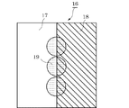
このマルチコア・マルチモードファイバ結合装置のうち好ましい例は,第1の集光系13によって第1のモード変換器15の所定の位置に光束が集められたものである。図2は,モード変換器の例を説明するための図である。図2に示されるように,このフェーズプレート16は,光ファイバ内の伝搬モードに合わせて空間光における隣り合う強度の位相差をπ(180°)にするために,光ファイバ内の伝搬モードに合わせて空間光における隣り合う強度分布に特定の屈折率をもった透明媒質を配置し,その波長における位相差相当の物理的な光路差を与えることを示している。本図では厚さが薄い部分17と厚さが厚い部分18で,それぞれに均等に照射されるよう配置された光19は,光路長が異なるため,モード変換が行われる。モード変換器の構成は,上記に限定されない。しかし,この方法を用いれば,シングルモードファイバからの基底モードの光の進行方向を光学系で調整することで,これらの複数の基底モードの光を一括して容易にモード変換できる。
A preferable example of the multi-core / multi-mode fiber coupling device is one in which the light beam is collected at a predetermined position of the
通常マルチコアファイバは,中心のコアから対称な位置に複数のコアを有する。そしてフェーズプレートは,通常厚さが薄い部分17と厚さが厚い部分18との境が直線状に存在する。本発明は,この境に一度集まったファイバからの光を,マルチコアのそれぞれのコアへと導く。
Usually, a multi-core fiber has a plurality of cores at symmetrical positions from the central core. The phase plate generally has a straight line between the
第2の集光系23は,第2のファイバ群21からの出射光群を集光するための光学系である。この例では,第2の集光系23により集光された第2のファイバ群21からの出射光群のモードをモード変換する第2のモード変換器は必須ではない。これは,マルチコア・マルチモードファイバに基底モードの光信号が含まれていても良いためである。一方,第2の集光系23により集光された第2のファイバ群21からの出射光群のモードを第2のモード変換器によりモード変更してもよい。
The second
マルチコアファイバ用空間結合系33は,第1のモード変換器15からの出射光群及び第2の集光系23からの出射光群をマルチコアファイバ31へ導くための光学系である。マルチコアファイバ用空間結合系33は,第1のモード変換器15からの出射光群及び第2の集光系23からの出射光群に含まれる複数の光のそれぞれを,マルチコア・マルチモードファイバにおける複数のコアのうち対応するコアへと導く。このような光学系の例は,特開2013−182222号公報に開示されたマルチコアファイバ結合装置における光学系である。
The multi-core fiber
マルチコアファイバ用空間結合系33の例は,図1に示されるように,第1のモード変換器15からの出射光群が入射する第1のリレーレンズ,第1のリレーレンズからの光と,第2の集光系23からの出射光群とをマルチコア・マルチモードファイバへ導くビームスプリッタとを含むものである。ビームスプリッタからの出力は,マルチモードファイバ結合レンズを経て,マルチモードファイバへと伝播し,光群のそれぞれの光は,目的とするコアへと伝播する。リレーレンズは,前方にある光学系で結像された像を,さらに後方に伝達するレンズおよびレンズ系を意味する。リレーレンズにより,マルチビームがフェーズプレートによって変換された既定の高次モードとファイバにおける同次のモードとのサイズの不一致を最適化し,最大の結合効率を得ることができる。
As shown in FIG. 1, the multi-core fiber
このように,第1のモード変換器15において,第1のファイバ群11からの出射光群に含まれる光を一括してモード変換することで,容易にマルチコア・マルチモードファイバ結合を達成できる。
As described above, in the
マルチコア・マルチモードファイバ31から出射された光は,マルチコアファイバ結合レンズ(マルチコアファイバ分離レンズ)61により分離され,光学系63により複数のファイバへ65と伝えられる。
The light emitted from the multicore /
本発明は,上記したマルチコア・マルチモードファイバ結合装置を用いたマルチコア・マルチモードファイバ結合方法をも提供する。この方法は,以下の工程を含む。 The present invention also provides a multi-core / multi-mode fiber coupling method using the multi-core / multi-mode fiber coupling device described above. This method includes the following steps.
第1のファイバ群11から出射光群が出射する。第1のファイバ群11からの前記出射光群が第1の集光系13により集光される。第1の集光系13にて集光された第1のファイバ群11からの出射光群が,第1のモード変換器15により第1のモードにモード変換される。
An outgoing light group is emitted from the
第2のファイバ群21から出射光群が出射する。第2のファイバ群21からの前記出射光群が第2の集光系23により集光される。第1のモード変換器15からの出射光群及び第2の集光系23からの出射光群が,マルチコアファイバ用空間結合系33により,マルチコアファイバ31へ導かれる。
An outgoing light group is emitted from the
図3は,マルチコア・マルチモードファイバ結合装置の好ましい例を示すブロック図である。図3に示される例は,先に挙げたマルチコア・マルチモードファイバ結合装置の構成に加え,第3のファイバ群41と,第3の集光系43と,第3のモード変換器45とをさらに有する。同様の原理を用いることで,さらに多数のモードの光群をマルチコア・マルチモードファイバへ導くことができる。第3の集光系43は,第3のファイバ群41からの出射光群を集光するための光学系である。第3のモード変換器45は,第3の集光系43にて集光された第3のファイバ群41からの出射光群の第2のモードにモードを変換するための光学機器である。第3のファイバ群41,第3の集光系43及び第3のモード変換器45は,それぞれ第1のファイバ群11,第1の集光系13,及び第1のモード変換器15と同様の構成を有する。
FIG. 3 is a block diagram showing a preferred example of a multi-core multi-mode fiber coupling device. The example shown in FIG. 3 includes a
この例の場合,マルチコアファイバ用空間結合系33は,第1のモード変換器15からの出射光群,第2の集光系23からの出射光群,及び第3のモード変換器45からの出射光群を,前記マルチコアファイバ31へ導く。
In this example, the multi-core fiber
本発明は,上記したマルチコア・マルチモードファイバ結合装置を用いたマルチコア・マルチモードファイバ結合方法をも提供する。この方法は,以下の工程を含む。 The present invention also provides a multi-core / multi-mode fiber coupling method using the multi-core / multi-mode fiber coupling device described above. This method includes the following steps.
第1のファイバ群11から出射光群が出射する。第1のファイバ群11からの前記出射光群が第1の集光系13により集光される。第1の集光系13にて集光された第1のファイバ群11からの出射光群が,第1のモード変換器15により第1のモードにモード変換される。
An outgoing light group is emitted from the
第2のファイバ群21から出射光群が出射する。第2のファイバ群21からの出射光群が第2の集光系23により集光される。
An outgoing light group is emitted from the
第3のファイバ群41から出射光群が出射する。第3のファイバ群41からの出射光群が第3の集光系43により集光される。第3の集光系43にて集光された第3のファイバ群41からの出射光群が,第3のモード変換器45により第2のモード(第2のファイバ群の光が第2のモードにモード変換されている場合は,第3のモード)にモード変換される。第1のモード変換器15からの出射光群,第2の集光系23からの出射光群及び第3のモード変換器45からの出射光群は,マルチコアファイバ用空間結合系33により,マルチコアファイバ31へ導かれる。
An outgoing light group is emitted from the
本発明は,空間分割多重及びマルチコア・マルチモードファイバを用いた光ファイバ通信の分野で利用されうる。 The present invention can be used in the field of optical fiber communication using space division multiplexing and multicore multimode fibers.
11・・第1のファイバ群 13・・第1の集光系 15・・第1のモード変換器
21・・第2のファイバ群 23・・第2の集光系
31・・マルチコアファイバ 33・・マルチコアファイバ用空間結合系
41・・第3のファイバ群 43・・第3の集光系 45・・第3のモード変換器
61・・マルチコアファイバ結合レンズ 63・・光学系
65・・ファイバ
11.
Claims (4)
第1のファイバ群(11)からの出射光群を集光する第1の集光系(13)と,
第1の集光系(13)にて集光された第1のファイバ群(11)からの出射光群のモードを第1のモードに変換する第1のモード変換器(15)と,
第2のファイバ群(21)と,
第2のファイバ群(21)からの出射光群を集光する第2の集光系(23)と,
第1のモード変換器(15)からの出射光群及び第2の集光系(23)からの出射光群 を合波してマルチコアファイバ(31)へ導くマルチコアファイバ用空間結合系(33)と,を有し,
第1のモード変換器(15)は,第1のファイバ群(11)からの出射光群のモードを ,第2のファイバ群(21)からの出射光群のモードとは異なる第1のモードに変換する
マルチコア・マルチモードファイバ結合装置。 A first fiber group (11);
A first condensing system (13) for condensing the outgoing light group from the first fiber group (11);
A first mode converter (15) for converting the mode of the light group emitted from the first fiber group (11) collected by the first light collection system (13) into a first mode;
A second fiber group (21);
A second condensing system (23) for condensing the outgoing light group from the second fiber group (21);
Outgoing light group from the first mode converter (15) and outgoing light group from the second condensing system (23) CombineA multi-core fiber spatial coupling system (33) leading to the multi-core fiber (31)And
The first mode converter (15) changes the mode of the light group emitted from the first fiber group (11). , To the first mode different from the mode of the outgoing light group from the second fiber group (21)
Multi-core / multi-mode fiber coupler.
第1のモード変換器(15)は,第1の集光系(13)によって前記第1のファイバ群(11)からの出射光群が一致した位置に設置されたフェーズプレートである
マルチコア・マルチモードファイバ結合装置。A multi-core multi-mode fiber coupling device according to claim 1,
The first mode converter (15) is a phase plate installed at a position where the emitted light groups from the first fiber group (11) coincide with each other by the first condensing system (13). Mode fiber coupler.
第3のファイバ群(41)と,
第3のファイバ群(41)からの出射光群を集光する第3の集光系(43)と,
第3の集光系(43)にて集光された第3のファイバ群(41)からの出射光群の第2のモードにモードを変換する第3のモード変換器(45)と,をさらに有し,
前記マルチコアファイバ用空間結合系(33)は,第1のモード変換器(15)からの出射光群,第2の集光系(23)からの出射光群,及び第3のモード変換器(45)からの出射光群を合波して,前記マルチコアファイバ(31)へ導くものであり,
第3のモード変換器(45)は,第3のファイバ群(41)からの出射光群のモードを ,第1のモード及び第2のファイバ群(21)からの出射光群のモードとは異なる第3の モードに変換する
マルチコア・マルチモードファイバ結合装置。A multi-core multi-mode fiber coupling device according to claim 1,
A third fiber group (41);
A third condensing system (43) for condensing the emitted light group from the third fiber group (41);
A third mode converter (45) for converting the mode into the second mode of the light group emitted from the third fiber group (41) collected by the third light collection system (43); In addition,
The multi-core fiber spatial coupling system (33) includes a group of light beams emitted from the first mode converter (15), a group of light beams emitted from the second light collecting system (23), and a third mode converter ( 45) that combines the outgoing light groups from the multi-core fiber (31) ,
The third mode converter (45) is configured to change the mode of the emitted light group from the third fiber group (41) to the mode of the emitted light group from the first mode and the second fiber group (21). A multi-core multi-mode fiber coupling device that converts to a different third mode .
第1のファイバ群(11)からの前記出射光群が第1の集光系(13)により集光される工程と,
第1の集光系(13)にて集光された第1のファイバ群(11)からの出射光群が,第1のモード変換器(15)により第1のモードにモード変換される工程と,
第2のファイバ群(21)から出射光群が出射する工程と,
第2のファイバ群(21)からの前記出射光群が第2の集光系(23)により集光される工程と,
第1のモード変換器(15)からの出射光群及び第2の集光系(23)からの出射光群が,マルチコアファイバ用空間結合系(33)により合波されてマルチコアファイバ(31)へ導かれる工程と,を含み,
第1のモード変換器(15)は,第1のファイバ群(11)からの出射光群のモードを ,第2のファイバ群(21)からの出射光群のモードとは異なる第1のモードに変換する
マルチコア・マルチモードファイバ結合方法。A step of emitting an emitted light group from the first fiber group (11);
A step of condensing the emitted light group from the first fiber group (11) by the first condensing system (13);
A step in which the light group emitted from the first fiber group (11) collected by the first light collection system (13) is mode-converted to the first mode by the first mode converter (15). When,
A step of emitting an emitted light group from the second fiber group (21);
A step of condensing the emitted light group from the second fiber group (21) by a second condensing system (23);
The outgoing light group from the first mode converter (15) and the outgoing light group from the second condensing system (23) are combined by the multi-core fiber space coupling system (33) to be multi-core fiber (31). a step that led to, only including,
The first mode converter (15) is a first mode in which the mode of the outgoing light group from the first fiber group (11) is different from the mode of the outgoing light group from the second fiber group (21). Multicore multimode fiber coupling method to convert to
Priority Applications (6)
| Application Number | Priority Date | Filing Date | Title |
|---|---|---|---|
| JP2014090704A JP5957718B2 (en) | 2014-04-24 | 2014-04-24 | Multi-core multi-mode fiber coupler |
| PCT/JP2015/060708 WO2015163124A1 (en) | 2014-04-24 | 2015-04-06 | Multicore/multimode fiber joining device |
| CN201580020765.4A CN106461868B (en) | 2014-04-24 | 2015-04-06 | Multicore multimode fibre coupling device |
| DK15782719.7T DK3136145T3 (en) | 2014-04-24 | 2015-04-06 | MULTICER / MULTI MODE FIBER CONNECTION DEVICE |
| EP15782719.7A EP3136145B1 (en) | 2014-04-24 | 2015-04-06 | Multicore/multimode fiber joining device |
| US15/306,104 US20170045687A1 (en) | 2014-04-24 | 2015-04-06 | Multicore/multimode fiber coupling device |
Applications Claiming Priority (1)
| Application Number | Priority Date | Filing Date | Title |
|---|---|---|---|
| JP2014090704A JP5957718B2 (en) | 2014-04-24 | 2014-04-24 | Multi-core multi-mode fiber coupler |
Publications (3)
| Publication Number | Publication Date |
|---|---|
| JP2015210339A JP2015210339A (en) | 2015-11-24 |
| JP2015210339A5 JP2015210339A5 (en) | 2016-04-21 |
| JP5957718B2 true JP5957718B2 (en) | 2016-07-27 |
Family
ID=54332291
Family Applications (1)
| Application Number | Title | Priority Date | Filing Date |
|---|---|---|---|
| JP2014090704A Active JP5957718B2 (en) | 2014-04-24 | 2014-04-24 | Multi-core multi-mode fiber coupler |
Country Status (6)
| Country | Link |
|---|---|
| US (1) | US20170045687A1 (en) |
| EP (1) | EP3136145B1 (en) |
| JP (1) | JP5957718B2 (en) |
| CN (1) | CN106461868B (en) |
| DK (1) | DK3136145T3 (en) |
| WO (1) | WO2015163124A1 (en) |
Families Citing this family (7)
| Publication number | Priority date | Publication date | Assignee | Title |
|---|---|---|---|---|
| FR3049135B1 (en) * | 2016-03-15 | 2020-02-14 | Cailabs | MULTIMODE FIBER OPTIC COMMUNICATIONS DEVICE WITH MODAL DISPERSION COMPENSATION COMPONENT |
| CN107797181B (en) * | 2016-08-31 | 2020-04-28 | 华为技术有限公司 | Optical switch matrix and control method thereof |
| CN108508536A (en) * | 2018-04-11 | 2018-09-07 | 武汉中科锐择光电科技有限公司 | A kind of complete optical fiber polarization beam splitter |
| CN112840256A (en) * | 2018-10-15 | 2021-05-25 | 住友电气工业株式会社 | Optical module and method for manufacturing optical module |
| CN116466445A (en) * | 2022-01-12 | 2023-07-21 | 华为技术有限公司 | Light receiving module, apparatus and method |
| WO2023176085A1 (en) * | 2022-03-17 | 2023-09-21 | 住友電気工業株式会社 | Multicore optical fiber, optical combiner, and fiber properties measurement method |
| CN115694645A (en) * | 2022-11-01 | 2023-02-03 | 南京信息工程大学 | Mode selection fiber core replacement multimode multi-core optical communication system with mold core balanced adjustment |
Family Cites Families (7)
| Publication number | Priority date | Publication date | Assignee | Title |
|---|---|---|---|---|
| WO2003036345A1 (en) * | 2001-10-19 | 2003-05-01 | Ntt Electronics Corporation | Array waveguide diffraction grating type optical multiplexer/branching filter |
| KR100594040B1 (en) * | 2004-01-08 | 2006-06-30 | 삼성전자주식회사 | Dual-band wavelength division multiplexer |
| EP2656137B1 (en) * | 2010-12-21 | 2015-09-16 | OFS Fitel, LLC | Multicore collimator |
| CN102096150B (en) * | 2010-12-22 | 2013-04-17 | 北京大学 | Multi-core fiber based optical transmission structure and device applying same |
| CN103185919B (en) * | 2011-12-30 | 2015-06-17 | 清华大学 | Coupling device of multimode optical fibers with cladding |
| JP5870426B2 (en) * | 2012-03-04 | 2016-03-01 | 国立研究開発法人情報通信研究機構 | Multi-core fiber coupler |
| US8867125B2 (en) * | 2012-08-24 | 2014-10-21 | Alcatel Lucent | Multi-mode optical fiber amplifier |
-
2014
- 2014-04-24 JP JP2014090704A patent/JP5957718B2/en active Active
-
2015
- 2015-04-06 US US15/306,104 patent/US20170045687A1/en not_active Abandoned
- 2015-04-06 EP EP15782719.7A patent/EP3136145B1/en active Active
- 2015-04-06 CN CN201580020765.4A patent/CN106461868B/en active Active
- 2015-04-06 DK DK15782719.7T patent/DK3136145T3/en active
- 2015-04-06 WO PCT/JP2015/060708 patent/WO2015163124A1/en active Application Filing
Also Published As
| Publication number | Publication date |
|---|---|
| WO2015163124A1 (en) | 2015-10-29 |
| DK3136145T3 (en) | 2021-09-06 |
| US20170045687A1 (en) | 2017-02-16 |
| CN106461868A (en) | 2017-02-22 |
| CN106461868B (en) | 2019-07-19 |
| EP3136145B1 (en) | 2021-07-14 |
| EP3136145A1 (en) | 2017-03-01 |
| JP2015210339A (en) | 2015-11-24 |
| EP3136145A4 (en) | 2017-12-20 |
Similar Documents
| Publication | Publication Date | Title |
|---|---|---|
| JP5957718B2 (en) | Multi-core multi-mode fiber coupler | |
| US9306670B2 (en) | Optical coupling/splitting device, two-way optical propagation device, and optical-transmit-receive system | |
| KR101399556B1 (en) | Method and device for transmitting optical information between an emitter station and receiving station via a multi-mode optical wave guide | |
| US9766405B2 (en) | System and method for photonic detection and excitation of multiple fibre modes | |
| US10122447B2 (en) | Free space optical receiver and free space optical receiving method | |
| KR101047121B1 (en) | Multichannel Optical Transmitter, and Active Alignment Method of Receiver | |
| JP4699369B2 (en) | Multimode optical transmission system and multimode optical transmission method | |
| JP6219288B2 (en) | Multi-core fiber and single-mode fiber optical connector | |
| Huang et al. | Structured directional coupler pair for multiplexing of degenerate modes | |
| JP6482126B2 (en) | Optical amplifier | |
| US20150372782A1 (en) | A novel mode division multiplexing optical link | |
| JP5753112B2 (en) | Multimode optical transmission system and multimode optical transmission method | |
| KR20170010478A (en) | Optical transmitting/receiving apparatus for input/output mode control and optical transmission system using the same | |
| US11516562B2 (en) | Core selective switch and optical node device | |
| JP7430993B2 (en) | Optical fiber parts, splitters and optical transmission systems | |
| JP2014013311A (en) | Optical fiber and optical communication system | |
| JP5553270B2 (en) | Optical communication system, optical transmitter, optical receiver, and optical communication method | |
| JP6992907B2 (en) | Optical amplifier and optical amplification method | |
| US7382980B2 (en) | Optical communication apparatus, optical communication information decoding method, optical switching system, and driving method for optical switching system | |
| JP6312198B2 (en) | Optical multiplexing device and optical demultiplexing device | |
| CN110149150B (en) | Column Vector Beam (CVB) based communication multiplexing system and method | |
| KR20100050024A (en) | A system for transmitting optical signal | |
| KR100301937B1 (en) | The method for increasing apace-compressed communication channel and optical multiplexer/demultiplexer using that | |
| JP2007019965A (en) | Receiver of light of multiplex spatial wavelength, multiplex transmitter of spatial wavelength and audiovisual system | |
| JP2006227506A (en) | Optical demultiplexer, diffraction grating and wave-multiplexed light transmission module |
Legal Events
| Date | Code | Title | Description |
|---|---|---|---|
| A621 | Written request for application examination |
Free format text: JAPANESE INTERMEDIATE CODE: A621 Effective date: 20160208 |
|
| A521 | Request for written amendment filed |
Free format text: JAPANESE INTERMEDIATE CODE: A523 Effective date: 20160208 |
|
| A871 | Explanation of circumstances concerning accelerated examination |
Free format text: JAPANESE INTERMEDIATE CODE: A871 Effective date: 20160208 |
|
| A521 | Request for written amendment filed |
Free format text: JAPANESE INTERMEDIATE CODE: A523 Effective date: 20160208 |
|
| TRDD | Decision of grant or rejection written | ||
| A975 | Report on accelerated examination |
Free format text: JAPANESE INTERMEDIATE CODE: A971005 Effective date: 20160510 |
|
| A01 | Written decision to grant a patent or to grant a registration (utility model) |
Free format text: JAPANESE INTERMEDIATE CODE: A01 Effective date: 20160517 |
|
| A61 | First payment of annual fees (during grant procedure) |
Free format text: JAPANESE INTERMEDIATE CODE: A61 Effective date: 20160526 |
|
| R150 | Certificate of patent or registration of utility model |
Ref document number: 5957718 Country of ref document: JP Free format text: JAPANESE INTERMEDIATE CODE: R150 |
|
| R250 | Receipt of annual fees |
Free format text: JAPANESE INTERMEDIATE CODE: R250 |
|
| R250 | Receipt of annual fees |
Free format text: JAPANESE INTERMEDIATE CODE: R250 |
|
| R250 | Receipt of annual fees |
Free format text: JAPANESE INTERMEDIATE CODE: R250 |
|
| R250 | Receipt of annual fees |
Free format text: JAPANESE INTERMEDIATE CODE: R250 |
|
| R250 | Receipt of annual fees |
Free format text: JAPANESE INTERMEDIATE CODE: R250 |