JP5957230B2 - Film fitting device - Google Patents
Film fitting device Download PDFInfo
- Publication number
- JP5957230B2 JP5957230B2 JP2012014899A JP2012014899A JP5957230B2 JP 5957230 B2 JP5957230 B2 JP 5957230B2 JP 2012014899 A JP2012014899 A JP 2012014899A JP 2012014899 A JP2012014899 A JP 2012014899A JP 5957230 B2 JP5957230 B2 JP 5957230B2
- Authority
- JP
- Japan
- Prior art keywords
- film
- label
- mandrel
- shot roller
- roller
- Prior art date
- Legal status (The legal status is an assumption and is not a legal conclusion. Google has not performed a legal analysis and makes no representation as to the accuracy of the status listed.)
- Expired - Fee Related
Links
- 230000002093 peripheral effect Effects 0.000 claims description 56
- 239000010408 film Substances 0.000 description 99
- 238000001514 detection method Methods 0.000 description 28
- 238000010380 label transfer Methods 0.000 description 27
- 239000000758 substrate Substances 0.000 description 26
- 239000000463 material Substances 0.000 description 18
- 238000007493 shaping process Methods 0.000 description 18
- 238000011144 upstream manufacturing Methods 0.000 description 6
- 230000001133 acceleration Effects 0.000 description 5
- 230000000694 effects Effects 0.000 description 4
- 230000015572 biosynthetic process Effects 0.000 description 3
- 238000006243 chemical reaction Methods 0.000 description 3
- 238000010586 diagram Methods 0.000 description 3
- 238000012840 feeding operation Methods 0.000 description 2
- 239000010409 thin film Substances 0.000 description 2
- 230000005540 biological transmission Effects 0.000 description 1
- 230000003247 decreasing effect Effects 0.000 description 1
- 239000002184 metal Substances 0.000 description 1
- 229920001225 polyester resin Polymers 0.000 description 1
- 239000004645 polyester resin Substances 0.000 description 1
- 229920005672 polyolefin resin Polymers 0.000 description 1
- 229920005990 polystyrene resin Polymers 0.000 description 1
- 238000000926 separation method Methods 0.000 description 1
- 238000004904 shortening Methods 0.000 description 1
- 229920006300 shrink film Polymers 0.000 description 1
Images


Landscapes
- Labeling Devices (AREA)
Description
この発明は、キャップシールやラベル等の筒状フィルムをボトル容器等の被嵌体に被嵌するフィルム被嵌装置、特に、薄肉の筒状フィルム等に適したフィルム被嵌装置に関する。 The present invention relates to a film fitting apparatus for fitting a tubular film such as a cap seal or a label onto a fitting body such as a bottle container, and more particularly to a film fitting apparatus suitable for a thin tubular film or the like.
薄肉フィルムによって形成された筒状ラベルLをボトル容器Bの胴部に被嵌するラベル被嵌装置としては、例えば、図15に示すようなものが開示されている。このフィルム被嵌装置90は、同図に示すように、筒状のラベルLが連続的に繋がった、シート状に折り畳まれた状態の長尺帯状のラベル形成基材Mを、円柱状のマンドレル91に被嵌することで所定状態に開口しながら、送給ローラ92によってマンドレル91の下部まで送給し、マンドレル91の中間部を取り囲むように、切断位置に設置されたカットユニット93によって所定長に順次切断することで個別のラベルLを形成した後、この開口された個別のラベルLをローラ94によって所定のラベル被嵌位置に順次送出することで、ラベル被嵌位置に順次搬送されてくる容器Bの胴部にラベルLを被嵌するようになっている。
As a label fitting apparatus for fitting a cylindrical label L formed of a thin film on the body of the bottle container B, for example, a device as shown in FIG. 15 is disclosed. As shown in the figure, the
前記ローラ94は、同図に示すように、ラベルLの送出方向に対して傾いた状態で配設されており、ラベルLをマンドレル91との間に挟み込んだ状態で、回転させることによって、ラベルLを周方向に回転させながら、下方側に送出するようになっている。
As shown in the figure, the
このように、ラベルLを周方向に回転させながら下方側に送出すると、筒状のラベルLが径方向外側に広がって、マンドレル91から突出したラベルLの下端部側が先すぼみしにくくなるので、薄肉フィルムによって形成されたラベルLであっても、ボトル容器Bの胴部に確実に被嵌することができるという利点がある。
In this way, when the label L is sent to the lower side while rotating in the circumferential direction, the cylindrical label L spreads outward in the radial direction, and the lower end side of the label L protruding from the
ところで、上述したようなラベル被嵌装置90では、マンドレル91の下端まで搬送したラベルLの下端部を、ローラ94とマンドレル91との間に挟み込んだ状態で待機させ、ボトル容器Bがラベル被嵌位置を通過する際に、その通過タイミングに合わせて、ローラ94を回転させて、ラベルLを周方向に回転させながら、マンドレル91の下方側に送出するといった具合に、ローラ94を間欠駆動させているので、図16に示すように、ローラ94が回転し始めてから、被嵌速度(ラベルLの下方向の移動速度)に対応する、ラベル送出方向の周速に換算した最終送出周速V0に到達するまでには、ある程度の加速時間Δtが必要となる。
By the way, in the
このように、ローラ94が回転し始めてから、最終送出周速V0に到達するまでの間は、ラベルLを被嵌速度(最終送出周速V0)で下方側に送出することができないので、ラベルLの送出を開始した後、ボトル容器Bの胴部に被嵌するまでに要する時間(被嵌時間)toを短縮するには限界がある。
As described above, since the label L cannot be sent downward at the fitting speed (final sending peripheral speed V0) from when the
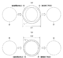
上述したように、ボトル容器Bをラベル被嵌位置で停止させずに、移動させながらラベルLを被嵌する場合、ラベルLの被嵌時間が長くなると、ラベルLをボトル容器Bに被嵌し始めてから、被嵌し終わるまでの間のボトル容器Bの移動距離が大きくなるので、図17(a)に示すように、ラベルLをボトル容器Bに確実に被嵌するためには、ラベルLの折径(直径D1)を大きくしなければならない。逆に、ラベルLの被嵌時間が短くなると、ラベルLをボトル容器Bに被嵌し始めてから、被嵌し終わるまでの間のボトル容器Bの移動距離が小さくなるので、同図(b)に示すように、ラベルLの折径(直径D2)を小さくしても、ラベルLをボトル容器Bに確実に被嵌することができる。しかしながら、上述したようなラベル被嵌位置では、被嵌時間を短縮するには限界があるので、折径を小さくするのにも限界があるということになる。 As described above, when the label L is fitted while being moved without stopping the bottle container B at the label fitting position, when the fitting time of the label L becomes long, the label L is fitted to the bottle container B. Since the movement distance of the bottle container B from the beginning to the end of the fitting increases, as shown in FIG. 17A, in order to fit the label L into the bottle container B securely, the label L The folding diameter (diameter D1) must be increased. On the contrary, when the fitting time of the label L is shortened, the movement distance of the bottle container B from the beginning of fitting the label L to the bottle container B to the end of fitting is reduced. As shown in FIG. 3, even if the folding diameter (diameter D2) of the label L is reduced, the label L can be reliably fitted to the bottle container B. However, at the label fitting position as described above, there is a limit to shortening the fitting time, and thus there is a limit to reducing the folding diameter.
そこで、この発明の課題は、筒状フィルムを被嵌体に被嵌するために要する被嵌時間を短縮することができるフィルム被嵌装置を提供することにある。 Then, the subject of this invention is providing the film fitting apparatus which can shorten the fitting time required in order to fit a cylindrical film on a to-be-fitted body.
上記の課題を解決するため、請求項1に係る発明は、筒状の長尺フィルムを順次切断することによって形成された所定長の筒状フィルムをマンドレルに被嵌することによって開口しながら、マンドレルに被嵌された筒状フィルムを下方側に順次送出することで、マンドレルの直下を通過する被嵌体に筒状フィルムを被嵌するようにしたフィルム被嵌装置において、長尺フィルムを所定長の筒状フィルムにカッタにより切断するフィルム切断手段と、前記フィルム切断手段と同期を取りながら、筒状フィルムまたは長尺フィルムを下方側に移送するフィルム移送手段と、前記フィルム切断手段及び前記フィルム移送手段の下方側に配設され、マンドレルに被嵌された筒状フィルムを、マンドレルとの間に挟み込んだ待機状態から、被嵌体の通過タイミングに合わせて所定の送出速度で下方側に送出する動作を行う間欠回転する上位ショットローラと、前記上位ショットローラによって下方側に送出された筒状フィルムをマンドレルとの間に常時挟み込める状態で配置され、上位ショットローラによって下方側に所定の送出速度で送出された筒状フィルムをマンドレルとの間に挟み込むことによって受け取り連続して下方側に送出することで、マンドレルの直下を通過する被嵌体に筒状フィルムを被嵌する動作を行う連続回転する下位ショットローラとを備え、前記上位ショットローラによる筒状フィルムの挟込位置と、下位ショットローラによる筒状フィルムの挟込位置との間隔が、筒状フィルムの長さより大きく設定されており、前記下位ショットローラは、その回転軸が前記マンドレルの軸芯に対して傾いた状態で配設されており、筒状フィルムを前記マンドレルとの間に挟み込んでいるときは、筒状フィルム送出方向の周速に換算した送出方向換算周速が予め設定された被嵌速度に対応する回転速度で定速回転していることを特徴とするフィルム被嵌装置を提供するものである。
In order to solve the above-mentioned problems, the invention according to
請求項2に係る発明は、請求項1に係る発明のフィルム被嵌装置において、前記下位ショットローラによる筒状フィルムの下方向の送出速度を、前記上位ショットローラによる筒状フィルムの下方向の送出速度より大きくしたことを特徴としている。 According to a second aspect of the present invention, in the film fitting apparatus according to the first aspect of the invention, the downward feeding speed of the cylindrical film by the lower shot roller is set to the downward feeding speed of the cylindrical film by the upper shot roller. It is characterized by being larger than the speed.
また、請求項3に係る発明は、筒状の長尺フィルムを順次切断することによって形成された所定長の筒状フィルムをマンドレルに被嵌することによって開口しながら、マンドレルに被嵌された筒状フィルムを下方側に順次送出することで、マンドレルの直下を通過する被嵌体に筒状フィルムを被嵌するようにしたフィルム被嵌装置において、長尺フィルムを所定長の筒状フィルムにカッタにより切断するフィルム切断手段と、前記フィルム切断手段と同期を取りながら、筒状フィルムまたは長尺フィルムを下方側に移送するフィルム移送手段と、前記フィルム切断手段及び前記フィルム移送手段の下方側に配設され、マンドレルに被嵌された筒状フィルムを、マンドレルとの間に挟み込んだ待機状態から、被嵌体の通過タイミングに合わせて所定の送出速度で下方側に送出する動作を行う間欠回転する上位ショットローラと、前記上位ショットローラによって下方側に送出された筒状フィルムをマンドレルとの間に常時挟み込める状態で配置され、上位ショットローラによって下方側に所定の送出速度で送出された筒状フィルムをマンドレルとの間に挟み込むことによって受け取り連続して下方側に送出することで、マンドレルの直下を通過する被嵌体に筒状フィルムを被嵌する動作を行う連続回転する下位ショットローラとを備え、下位ショットローラは、その回転軸がマンドレルの軸芯に対して傾いた状態で配設されており、筒状フィルムを上位ショットローラから受け取る時点では、上位ショットローラの筒状フィルム送出方向の周速に換算した送出方向換算周速と下位ショットローラの筒状フィルム送出方向の周速に換算した送出方向換算周速とが略一致しており、下位ショットローラは、受け取った筒状フィルムが上位ショットローラから離れた後に増速するようになっていることを特徴とするフィルム被嵌装置を提供するものである。 According to a third aspect of the present invention, there is provided a cylinder fitted on a mandrel while opening by fitting a cylindrical film of a predetermined length formed by sequentially cutting a cylindrical long film on the mandrel. In a film fitting apparatus in which a tubular film is fitted onto a fitted body that passes directly under a mandrel by sequentially sending the shaped film downward, a long film is cut into a tubular film of a predetermined length. A film cutting means for cutting the film, a film transferring means for transferring a cylindrical film or a long film to the lower side while synchronizing with the film cutting means, and a lower side of the film cutting means and the film transferring means. is set, the tubular film that is fitted onto the mandrel, from the standby state sandwiched between the mandrel, in accordance with the passing timing of the Hamakarada An upper shot roller rotates intermittently performs the operation of sending to the lower side at a constant delivery rate, are arranged in a constantly Hasamikomeru state between the mandrel tubular film delivered to the lower side by the upper shot rollers, upper The cylindrical film sent to the lower side by the shot roller at a predetermined delivery speed is sandwiched between the mandrel and continuously sent to the lower side to form a cylindrical shape on the fitted body that passes directly under the mandrel. A lower shot roller that rotates continuously to perform the operation of fitting the film, and the lower shot roller is disposed with its rotation axis inclined with respect to the axis of the mandrel. At the time of receiving from the roller, the peripheral speed in the sending direction converted to the peripheral speed in the cylindrical film sending direction of the upper shot roller and the lower shot The circumferential speed in the feed direction converted to the circumferential speed in the cylindrical film feed direction of the Troller is substantially the same, and the lower shot roller increases the speed after the received cylindrical film leaves the upper shot roller. It is intended to provide a film-covering device characterized by the above.
請求項4に係る発明は、請求項1、2または3に係る発明のフィルム被嵌装置において、前記上位ショットローラは、その回転軸が前記マンドレルの軸芯に対して傾いた状態で配設されていることを特徴としている。 According to a fourth aspect of the present invention, in the film fitting apparatus according to the first, second, or third aspect of the invention, the upper shot roller is disposed in a state in which the rotation shaft is inclined with respect to the axis of the mandrel. It is characterized by having.
請求項5に係る発明は、請求項1、2、3または4に係る発明のフィルム被嵌装置において、被嵌体は、その頭部が胴部よりも小径であり、前記マンドレルの下端部には、被嵌体の搬送方向に延びる溝部が形成されており、被嵌体が前記マンドレルの直下を通過する際は、被嵌体の小径の頭部が前記溝部内を通過するようになっていることを特徴としている。
The invention according to claim 5 is the film fitting apparatus according to
以上のように、請求項1に係る発明のフィルム被嵌装置では、マンドレルに被嵌された筒状フィルムを被嵌体に被嵌する動作を行う連続回転する下位ショットローラが、筒状フィルムをマンドレルとの間に挟み込んでいるときは、筒状フィルム送出方向の周速に換算した送出方向換算周速が予め設定された被嵌速度に対応する回転速度で定速回転しているので、ショットローラを間欠駆動させているため、ショットローラが回転し始めてから、所定の被嵌速度(ショットローラの最終送出周速)に到達するまでには、ある程度の加速時間が必要となる従来のフィルム被嵌装置とは異なり、筒状フィルムを送出開始時点から被嵌速度で送出することができ、加えて、筒状フィルムを周方向に回転させながら下方側に送出できる。 As described above, in the film fitting apparatus according to the first aspect of the present invention, the continuously rotating lower shot roller that performs the operation of fitting the tubular film fitted onto the mandrel onto the fitted body includes the tubular film. When sandwiched between the mandrel and the mandrel, since the sending direction converted peripheral speed converted to the peripheral speed in the cylindrical film sending direction is rotating at a constant speed at the rotation speed corresponding to the preset fitting speed, the shot Since the roller is driven intermittently, it takes a certain amount of acceleration time from the time when the shot roller starts to rotate until it reaches a predetermined covering speed (final sending peripheral speed of the shot roller). Unlike fitting device can be delivered at the fitting speed tubular film from the delivery start time, in addition, Ru can throw downward while rotating the tubular film in a circumferential direction.
従って、従来のフィルム被嵌装置に比べて、筒状フィルムの送出開始後、筒状フィルムを被嵌体に被嵌するまでに要する時間(被嵌時間)を短縮することができ、これに伴って、筒状フィルムの折径を小さくすることができるという効果が得られる。 Therefore, compared with the conventional film-fitting device, the time (fitting time) required for fitting the tubular film to the fitting object after the delivery of the tubular film can be shortened. Thus, an effect that the folding diameter of the tubular film can be reduced is obtained.
また、請求項2に係る発明は、下位ショットローラによる筒状フィルムの下方向の送出速度を、上位ショットローラによる筒状フィルムの下方向の送出速度より大きくしたので、被嵌時間をさらに短縮することができると共に、筒状フィルムの折径をさらに小さくすることができる。
Further, the invention according to
また、請求項3に係る発明は、連続回転する下位ショットローラが間欠回転する上位ショットローラから筒状フィルムを受け取る時点では、下位ショットローラの筒状フィルム送出方向の周速に換算した送出方向換算周速が上位ショットローラの筒状フィルム送出方向の周速に換算した送出方向換算周速と略一致しており、下位ショットローラは、筒状フィルムを受け取った後に筒状フィルムを周方向に回転させながら増速するようになっているので、ショットローラを間欠駆動させているため、停止状態から被嵌速度まで加速させる従来のフィルム被嵌装置とは異なり、所定の被嵌速度に到達するまでに要する加速時間が短くなり、その結果、従来のフィルム被嵌装置に比べて被嵌時間を短くすることができ、これに伴って、筒状フィルムの折径を小さくすることができるという効果が得られる。 In the invention according to claim 3, when the cylindrical film is received from the upper shot roller in which the continuously rotating lower shot roller intermittently rotates, the feeding direction converted into the peripheral speed of the lower shot roller in the cylindrical film feeding direction. The peripheral speed is substantially the same as the peripheral speed in the sending direction converted to the peripheral speed in the cylindrical film sending direction of the upper shot roller, and the lower shot roller rotates the cylindrical film in the circumferential direction after receiving the cylindrical film. Since the shot roller is driven intermittently because the speed is increased while being different from the conventional film fitting apparatus that accelerates from the stopped state to the fitting speed, until the predetermined fitting speed is reached. Acceleration time required for this is shortened, and as a result, the fitting time can be shortened as compared with the conventional film fitting device. There is an advantage that it is possible to reduce the folded diameter.
また、請求項4に係る発明では、双方の回転軸がマンドレルの軸芯に対して傾いた状態で上位ショットローラ及び下位ショットローラが配設されているので、筒状フィルムが周方向に回転しながら、上位ショットローラから下位ショットローラに引き渡されることになり、筒状フィルムの上位ショットローラから下位ショットローラへの受け渡しを円滑に行うことができる。 In the invention according to claim 4, since the upper shot roller and the lower shot roller are disposed in a state in which both rotation shafts are inclined with respect to the axis of the mandrel, the cylindrical film rotates in the circumferential direction. However, the upper shot roller is handed over to the lower shot roller, and the cylindrical film can be smoothly transferred from the upper shot roller to the lower shot roller.
ところで、この種のフィルム被嵌装置では、シート状に折り畳まれた筒状フィルムを、マンドレルに被嵌することによって開口しているので、マンドレルから飛び出した筒状フィルムの下端部側は、折目のスプリングバックによって、元のシート状に戻ろうとしてすぼんでしまい、頭部が胴部よりも小径の被嵌体に筒状フィルムを被嵌する場合は、筒状フィルムの下端部が被嵌体の肩部に当接して、筒状フィルムを円滑かつ確実に被嵌体に被嵌することができないといった問題がある。 By the way, in this kind of film covering apparatus, since the tubular film folded in a sheet shape is opened by covering the mandrel, the lower end side of the tubular film protruding from the mandrel is a crease. When the tubular film is fitted into a fitting body whose head is smaller in diameter than the trunk portion, the lower end portion of the tubular film is the fitting body. There is a problem that the tubular film cannot be fitted onto the fitted body smoothly and reliably.
しかしながら、請求項5に係る発明のフィルム被嵌装置では、マンドレルの下端部に、被嵌体の搬送方向に延びる溝部が形成されており、被嵌体がマンドレルの直下を通過する際は、被嵌体の小径の頭部が溝部内に入り込んだ状態となっているので、被嵌体がマンドレルの直下を通過するときは、マンドレルの下端と被嵌体の大径の胴部とが接近した状態となっている。従って、マンドレルから飛び出した筒状フィルムは、その下端部が大きくすぼまない状態で被嵌体の胴部に被嵌され始めるので、筒状フィルムの下端部が被嵌体の肩部に当接しにくく、筒状フィルムを円滑かつ確実に被嵌体に被嵌することができる。 However, in the film fitting apparatus according to the fifth aspect of the present invention, the lower end of the mandrel has a groove extending in the conveying direction of the fitted body, and when the fitted body passes directly under the mandrel, Since the small-diameter head of the fitting is in the groove, the lower end of the mandrel and the large-diameter trunk of the fitted body approach each other when the fitted body passes directly under the mandrel. It is in a state. Accordingly, the tubular film that has jumped out of the mandrel starts to be fitted into the body of the fitting body with the lower end of the tubular film not greatly squeezed, so that the lower end of the tubular film hits the shoulder of the fitting body. It is difficult to touch, and the tubular film can be smoothly and reliably fitted to the fit object.
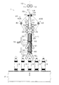
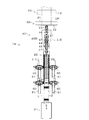
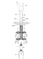
以下、実施の形態について図面を参照して説明する。図1及び図2は、ポリエステル系樹脂、ポリスチレン系樹脂、ポリオレフィン系樹脂等からなる厚さ15〜40μmのシュリンクフィルムに印刷等を施して形成された筒状のラベルLをボトル容器Bの胴部に被嵌するラベル被嵌装置1を示している。このラベル被嵌装置1は、同図に示すように、筒状のラベルLが連続的に繋がった、シート状に折り畳まれた状態のラベル形成基材LMから個別のラベルLを切り離しながら、このラベルLをラベル被嵌位置αに順次送出することで、ボトル搬送装置2によって所定の搬送ピッチでラベル被嵌位置αに順次搬送されてくるボトル容器Bの胴部に被嵌するようになっており、筒状ラベル供給装置に装着されたラベルロール(図示せず)から繰り出されたラベル形成基材LMを切断位置に断続的に送出する駆動ローラ11及び従動ローラ12からなる基材送出ユニット10と、この基材送出ユニット10によって送出されてきたラベル形成基材LMを被嵌することによって所定状態に開口するマンドレル20と、基材送出ユニット10とマンドレル20との間に配設された、ラベル形成基材LMを所定のカットピッチで順次切断することで、個別のラベルLを形成する固定刃31及び可動刃32からなるギロチン方式の基材切断ユニット30と、マンドレル20に被嵌した状態で切り離されたラベルLをマンドレル20の下方側に断続的に移送するラベル移送手段40と、このラベル移送手段40によって移送されてきたラベルLを受け取ってマンドレル20の下端側に送出する一対の上位ショットローラ50と、この上位ショットローラ50によって送出されてきたラベルLを受け取ってラベル被嵌位置αに送出する一対の下位ショットローラ60とを備えている。
Hereinafter, embodiments will be described with reference to the drawings. 1 and 2 show a cylindrical label L formed by printing on a shrink film having a thickness of 15 to 40 μm made of polyester resin, polystyrene resin, polyolefin resin, etc. The
前記マンドレル20は、図1〜図3に示すように、上端側が先細楔状のラベル開口部21と、このラベル開口部21の下部に連設された断面円形状のラベル整形部25とを備えており、ラベル開口部21の上端部に被嵌されたラベル形成基材LMがラベル開口部21の下方側に移送されることによって徐々に開口されていき、個別のラベルLに切り離された後、ラベル整形部25に被嵌されることで円筒状に整形されるようになっている。
As shown in FIGS. 1 to 3, the
前記ラベル開口部21の下半部には、ボトル容器Bの搬送方向の上流側及び下流側の側面に、周面が僅かに突出した状態で、一対の上位ローラ22、一対の中位ローラ23及び一対の下位ローラ24がそれぞれ回転可能に取り付けられており、ラベル開口部21の両側面には、各中位ローラ23の周面下部を露出させる窪み部21aが形成されている。
In the lower half of the
前記ラベル整形部25の外周面には、ラベルLとの接触面積を少なくするために、多数の縦溝VGが形成されており、ラベル整形部25の上半部25aの下端には、ボトル容器Bの搬送方向に直交する位置に、一対の上位ショットローラ50との間にラベルLを挟み込む一対のローラ26が、その周面が僅かに突出した状態で、回転可能に取り付けられていると共に、ラベル整形部25の下半部25bの下端には、ボトル容器Bの搬送方向に直交する位置に、一対の下位ショットローラ60との間にラベルLを挟み込む一対のローラ27が、その周面が僅かに突出した状態で、回転可能に取り付けられている。
A large number of vertical grooves VG are formed on the outer peripheral surface of the
また、ローラ26とローラ27との間隔は、上位ショットローラ50と下位ショットローラ60とが同一のラベルLを同時に挟み込まないように、ラベルLの長さより僅かに大きく設定されている。
The interval between the
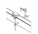
また、ボトル容器Bの搬送方向の上流側には、反射型の光電センサからなるラベル検出センサ70が配設されていると共に、マンドレル20におけるラベル整形部25の上半部25aの下端には、ラベル検出センサ70から射出された光を反射する反射鏡71が取り付けられており、ラベル移送手段40によってマンドレル20の下端位置まで移送されてきたラベルLを検出するようになっている。
Further, on the upstream side in the transport direction of the bottle container B, a
また、図4に示すように、ラベル被嵌位置α付近におけるボトル容器Bの搬送方向の上流側には、ボトル容器Bの搬送経路を挟んでその両側に、反射型の光電センサからなるボトル検出センサ72と、このボトル検出センサ72から射出された光を反射する反射鏡73とが配設されており、ボトル搬送装置2によって搬送されてくるボトル容器Bを、ラベル被嵌位置αの直前位置で検出するようになっている。
Further, as shown in FIG. 4, on the upstream side in the transport direction of the bottle container B in the vicinity of the label fitting position α, the bottle detection is made of a reflective photoelectric sensor on both sides of the transport path of the bottle container
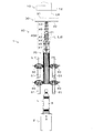
前記ラベル移送手段40は、図1及び図2に示すように、マンドレル20のラベル開口部21に被嵌した状態で、基材切断ユニット30によってラベル形成基材LMから切り離されたラベルLを、ラベル開口部21との間に挟み込んでラベル整形部25に移送する、マンドレル20におけるボトル容器Bの搬送方向の上流側及び下流側にそれぞれ配設されたフィードベルトユニット40A、40Bから構成されており、フィードベルトユニット40A、40Bは、それぞれ駆動プーリ41と4個の従動プーリ42、43、44、45と、これらに掛け渡されるフィードベルト46とから構成されている。
As shown in FIGS. 1 and 2, the label transfer means 40 is attached to the
前記駆動プーリ41及び従動プーリ44、45は、マンドレル20におけるラベル開口部21の下位ローラ24及び上位ローラ22、中位ローラ23に対応する位置にそれぞれ配設されており、下位ローラ24及び上位ローラ22、中位ローラ23との間にフィードベルト46を介して、ラベルLを挟み込むようになっている。
The driving
フィードベルトユニット40A、40Bの駆動プーリ41及び従動プーリ44、45は、それぞれ同一の支持部材に回転可能に支持されており、従動プーリ45が、マンドレル20におけるラベル開口部21に形成された窪み部21aに入り込むことで、中位ローラ23を介して、マンドレル20を支持するようになっている。
The
前記フィードベルト46は、基材送出ユニット10の駆動ローラ11と同期を取りながら、基材送出ユニット10によるラベル形成基材LMの送出速度と同一速度でラベル形成基材LMをマンドレル20のラベル整形部25に移送するが、基材送出ユニット10によるラベル形成基材LMの送出が停止され、基材切断ユニット30がラベル形成基材LMを切断した後は、切り離されたラベルLを、基材送出ユニット10によるラベル形成基材LMの送出速度より速い速度でマンドレル25のラベル整形部25に移送するようになっている。
The
一対の上位ショットローラ50及び一対の下位ショットローラ60は、図1及び図2に示すように、それぞれ一方がボトル容器Bの搬送方向の下流側に向かって下がり傾斜に、他方がボトル容器Bの搬送方向の上流側に向かって下がり傾斜になるように、それぞれの回転軸がマンドレル20の軸芯に対して30度傾いた状態、即ち、マンドレル20の軸芯に対して上位ショットローラ50及び下位ショットローラ60が60度傾いた状態で、ボトル容器Bの搬送経路を挟んで両側に配設されており、図3(a)に示すように、マンドレル20におけるラベル整形部25の各ローラ26及び各ローラ27も対応する一対の上位ショットローラ50及び一対の下位ショットローラ60と同方向に傾斜するように、それぞれの回転軸がマンドレル20の軸芯に対して30度傾いた状態でラベル整形部25にそれぞれ取り付けられている。
As shown in FIGS. 1 and 2, each of the pair of
各上位ショットローラ50及び各下位ショットローラ60は、サーボモータからなるショットローラモータ51、61の回転軸にそれぞれ直結されており、各ショットローラモータ51、61を、それぞれの回転軸がマンドレル20の軸芯に対して逆方向に30度傾斜させた状態で支持することにより、各上位ショットローラ50及び各下位ショットローラ60を、それぞれ逆方向に傾斜させた状態で、それぞれの外周面をラベル整形部25の対応するローラ26、27の外周面に略接触させるようになっている。
Each
従って、マンドレル20に被嵌されたラベルLを、上位ショットローラ50や下位ショットローラ60と、マンドレル20のラベル整形部25との間に挟み込んで上位ショットローラ50や下位ショットローラ60を回転させると、ラベルLが周方向に回転しながら下方側に送出されることになる。
Therefore, when the label L fitted on the
図5は、このラベル被嵌装置1及びボトル搬送装置2から構成されるラベル装着システムの電気的構成を示すブロック図である。このラベル装着システムは、容器搬送制御装置2A及びラベル制御装置1Aを備えており、容器搬送制御装置2Aには、ラベル制御装置1Aが接続され、容器搬送制御装置2A及びラベル制御装置1Aの間では、ラベル装着動作に関するデータ及び制御信号等が互いに入出力されるようになっている。
FIG. 5 is a block diagram showing an electrical configuration of a label mounting system including the label
前記容器搬送制御装置2Aには、ボトル搬送装置2のコンベア2aを動作させるためのコンベアモータ2bを駆動するインバータ81が接続されており、コンベア2aを動作させるための制御信号をインバータ81に出力すると、インバータ81からコンベアモータ2bに対して駆動信号が出力され、これにより、コンベアモータ2bが回転駆動され、コンベア2aがラベル被嵌装置1に向けてボトル容器Bを搬送する。
The container
また、容器搬送制御装置2Aには、ボトル搬送装置2に搭載されたスクリュー等の容器ピッチ切り装置2cを動作させるための容器ピッチ切りモータ2dを駆動するインバータ82が接続されており、容器ピッチ切り装置2cを動作させるための制御信号をインバータ82に出力すると、インバータ82から容器ピッチ切りモータ2dに対して駆動信号が出力され、これにより、容器ピッチ切りモータ2dが回転駆動され、容器ピッチ切り装置2cがボトル容器Bを所定の搬送ピッチで搬送する。
The container
また、容器搬送制御装置2Aは、コンベアモータ2b及び容器ピッチ切りモータ2dの回転速度を変化させることが可能とされ、これらの回転速度が変化されることにより、ボトル容器Bの搬送速度を変化させることができる。
Further, the container
前記ラベル制御装置1Aは、図示しないマイクロコンピュータを備えており、容器搬送制御装置2Aからの指令及び予め記憶された動作プログラムに基づいて、基材送出ユニット10の駆動ローラ11、基材切断ユニット30の可動刃32、ラベル移送手段40のフィードベルト46、上位ショットローラ50及び下位ショットローラ60の各動作を制御するものである。ラベル制御装置1Aには、各種のデータを記憶するための図示しないメモリが備えられている。
The
また、ラベル制御装置1Aには、操作表示装置83が接続されており、センサアンプ88、89を介して、ラベル検出センサ70及びボトル検出センサ72が接続されている。
In addition, an
前記ラベル制御装置1Aには、基材送出ユニット10の駆動ローラ11を回転駆動するためのサーボモータからなるピッチ送りモータ10aを制御するサーボアンプ84が接続されており、ラベル検出センサ70及びボトル検出センサ72から出力されるラベル検出信号及びボトル検出信号に基づいて、駆動ローラ11を回転動作させるための制御信号をサーボアンプ84に出力すると、サーボアンプ84からピッチ送りモータ10aに対して駆動信号が出力され、これにより、ピッチ送りモータ10aが駆動して、駆動ローラ11が回転する。
The
前記ラベル制御装置1Aには、可動刃32を駆動するためのサーボモータからなる可動刃モータ30aを制御するサーボアンプ85が接続されており、ラベル検出センサ70及びボトル検出センサ72から出力されるラベル検出信号及びボトル検出信号に基づいて、可動刃32を進退動作させるための制御信号をサーボアンプ85に出力すると、サーボアンプ85から可動刃モータ30aに対して駆動信号が出力され、これにより、可動刃モータ30aが駆動して、可動刃32が固定刃31に対して進退する。
The
前記ラベル制御装置1Aには、フィードベルト46が掛け渡された駆動プーリ41を回転駆動するためのサーボモータからなるフィードベルトモータ40aを制御するサーボアンプ86が接続されており、ラベル検出センサ70及びボトル検出センサ72から出力されるラベル検出信号及びボトル検出信号に基づいて、駆動プーリ41を回転動作させるための制御信号をサーボアンプ86に出力すると、サーボアンプ86からフィードベルトモータ40aに対して駆動信号が出力され、これにより、フィードベルトモータ40aが回転駆動され、駆動プーリ41が回転してフィードベルト46が循環移動する。
The
前記ラベル制御装置1Aには、上位ショットローラ50を回転駆動するためのショットローラモータ51を制御するサーボアンプ87aが接続されており、ラベル検出センサ70及びボトル検出センサ72から出力されるラベル検出信号及びボトル検出信号に基づいて、上位ショットローラ50を回転動作させるための制御信号をサーボアンプ87aに出力すると、サーボアンプ87aからショットローラモータ51に対して駆動信号が出力され、これにより、ショットローラモータ51が回転駆動され、上位ショットローラ50が回転する。
The
前記ラベル制御装置1Aには、下位ショットローラ60を回転駆動するためのショットローラモータ61を制御するサーボアンプ87bが接続されており、下位ショットローラ60を回転動作させるための制御信号をサーボアンプ87bに出力すると、サーボアンプ87bからショットローラモータ61に対して駆動信号が出力され、これにより、ショットローラモータ61が回転駆動され、下位ショットローラ60が回転する。
The
以下、このラベル被嵌装置1の動作について、図6に示すタイミングチャートを参照しながら説明する。まず、図1及び図2に示す待機状態において、上述したボトル検出センサ72によってボトル容器Bが検出されると(T0)、上位ショットローラ50が回転を開始し、ラベル整形部25の上半部25aに被嵌されているラベルL(L1)を周方向に回転させながらラベル整形部25の下半部25bに送出し始める。上位ショットローラ50は、最終周速Vcまで急速に加速した後、最終周速Vcで所定時間回転し、ラベルLが上位ショットローラ50から離れた後に回転を停止する(T1)。
Hereinafter, operation | movement of this
前記下位ショットローラ60は、装置の運転中は、上位ショットローラ50の最終周速Vcの約3倍の周速Vdで、常時、定速回転しており、ラベルL(L1)の上端がショットローラ50から離れた瞬間に、下位ショットローラ60がマンドレル20との間に挟み込むことによってラベルL(L1)を受け取り、周方向に回転させながら下方側に送出することで、ラベル被嵌位置αを通過するボトル容器Bにタイミングを合わせて、その胴部に被嵌する。
The
また、ボトル検出センサ72によってボトル容器Bが検出されると(T0)、ラベル移送手段40も駆動を開始し、マンドレル20のラベル開口部21との間に把持している次のラベルL(L2)をマンドレル20のラベル整形部25に移送し始め、ラベルL(L2)の下端部が上位ショットローラ50に把持される直前位置まできたときに、ラベルLの移送動作を一旦停止する(T2)。このとき、ラベルL(L2)の上端部は、ラベル移送手段40のフィードベルト46とラベル開口部21との間に把持された状態となっている。
When the bottle container B is detected by the bottle detection sensor 72 (T0), the label transfer means 40 also starts to drive, and the next label L (L2) held between the
また、ラベル移送手段40が駆動を開始した後、ラベルLの移送動作を一旦停止するまでの間(T0〜T2)に、基材送出ユニット10がラベル形成基材LMを下方側に送出することで、ラベル形成基材LMがマンドレル20のラベル開口部21に被嵌され、ラベル移送手段40によって、その下端部がラベル開口部21の下半部当りまで移送されており、切断位置からラベル形成基材LMの下端までの距離がラベル長に一致している。そして、ラベル移送手段40が駆動を停止している間に、基材切断ユニット30がラベル形成基材LMを切断することで、ラベル移送手段40のフィードベルト46とラベル開口部21との間に把持された状態で、ラベルLが切り離される。
In addition, after the label transfer means 40 starts to be driven and until the label L transfer operation is temporarily stopped (T0 to T2), the base
ラベル移送手段40が駆動を停止した後、所定時間が経過した時点(T3)において、ラベル移送手段40及び上位ショットローラ50が共に駆動を再開し、マンドレル20に被嵌されている上位及び下位の2枚のラベルLが僅かに下方側に移送され、下位のラベルL(L2)がラベル移送手段40から上位ショットローラ50に引き渡される。このとき、ラベル移送手段40のフィードベルト46の移動速度Vb1と、上位ショットローラ50の周速Vc1の1/2が略等しくなるように設定されている。
When the predetermined time has elapsed after the
なお、上述したように、マンドレル20の軸芯に対してθ=60度傾いた状態で配設されている上位ショットローラ50を回転させると、マンドレル20と上位ショットローラ50との間に挟み込まれたラベルLは、上位ショットローラ50の周速Vc1×cosθ=Vc1/2で下方側に送出されるのでラベル移送手段40と上位ショットローラ50との間のラベルLの受渡速度が、ラベル移送手段40と上位ショットローラ50とで一致することになる。
As described above, when the
ただし、このラベル被嵌装置1では、ラベルLをラベル移送手段40のフィードベルト46から上位ショットローラ50に引き渡す際、フィードベルト46と上位ショットローラ50とがラベルLを同時に把持することはなく、ラベルLがフィードベルト46から離れた後に、上位ショットローラ50がラベルLを受け取ることができるように、ラベル移送手段40と上位ショットローラ50との間隔が設定されている。
However, in this label
また、ラベル移送手段40は、ラベルLがフィードベルト46から離れると同時に停止動作(減速−停止)を実行するが、上位ショットローラ50は、ラベル検出センサ70によってラベルLの下端部が検出されるまで定速回転を継続し、ラベル検出センサ70によってラベルLが検出された時点(T4)において、ショットローラ50の停止信号が出力され、停止動作(減速−停止)を実行する。
The label transfer means 40 performs a stop operation (deceleration-stop) as soon as the label L leaves the
このようにして、図1及び図2に示す待機状態となり、以下、同様の動作を繰り返すことになる。 In this way, the standby state shown in FIGS. 1 and 2 is entered, and the same operation is repeated thereafter.
なお、上述したように、マンドレル20の中心軸に対する上位ショットローラ50及び下位ショットローラ60の傾斜角度が60°であるので、上位ショットローラ50や下位ショットローラ60の周速をVとすると、上位ショットローラ50や下位ショットローラ60によるラベルLの下方側への送出速度Vf=V×cos60°、ラベルLの回転速度(周速)Vr=V×sin60°となり、下方側への送出速度Vfを上位ショットローラ50や下位ショットローラ60の「送出方向換算周速」と呼ぶことにする。
As described above, since the inclination angle of the
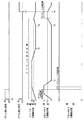
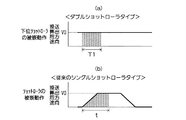
以上のように、このラベル被嵌装置1では、図7(a)、(b)に示すように、従来のラベル被嵌装置の被嵌速度に対応するショットローラの送出方向換算周速である最終送出周速V0よりも大きい送出方向換算周速である被嵌周速V1で、常時、定速回転している下位ショットローラ60によってマンドレル20に被嵌されたラベルLをボトル容器Bの胴部に被嵌するようにしているので、同図(b)に示すように、単一のショットローラを間欠駆動させているため、ショットローラが回転し始めてから、所定の被嵌速度(ショットローラの最終送出周速V0)に到達するまでには、ある程度の加速時間が必要となる従来のラベル被嵌装置とは異なり、ラベルLを被嵌開始時点から被嵌速度(下位ショットローラ60の被嵌周速V1)で送出することができる。従って、従来のラベル被嵌装置の被嵌時間tに比べて、このラベル被嵌装置1の被嵌時間Tを大きく短縮することができ、これに伴って、ラベルLの折径を小さくすることができるという効果が得られる。具体的に説明すると、例えば、長さ160mmのラベルLを従来のラベル被嵌装置で被嵌する場合、被嵌時間tが40.5msで、その間のボトル容器の移動距離は8.3mmであるが、このラベル被嵌装置1を用いて同様のラベルLをボトル容器Bに被嵌すると、その被嵌時間Tは7.6msで、その間のボトル容器Bの移動距離は1.57mmとなる。従って、このラベル被嵌装置1を使用すると、従来の装置を使用する場合に比べて、ラベルLの折径を3.5mm程度小さくすることができる。なお、図7(a)、(b)におけるそれぞれの網掛け表示部分の面積がラベルを被嵌する際のラベルの移動距離を示しており、同図(a)に示すラベル被嵌装置1における網掛け表示部分と、同図(b)に示す従来の被嵌装置における網掛け表示部分とは同一面積になっている。
As described above, in this label
従来のラベル被嵌装置のように、間欠回転する単一のショットローラによって、ラベルLをボトル容器Bの胴部に被嵌する場合は、間欠回転するショットローラの最終送出周速V0に対応する回転速度を極端に大きくすることはできないが、このラベル被嵌装置1では、間欠回転する上位ショットローラ50によって送出したラベルLを連続回転する下位ショットローラ60が受け取ってボトル容器Bの胴部に被嵌するダブルショットローラ方式を採用しているので、連続回転する下位ショットローラ60の回転速度を間欠回転する上位ショットローラ50の回転速度の3倍程度まで増速することが可能となり、従来のラベル被嵌装置に比べて、ラベルLの被嵌時間を飛躍的に短縮することができる。
When the label L is fitted onto the body of the bottle container B by a single shot roller that rotates intermittently as in the conventional label fitting device, this corresponds to the final delivery peripheral speed V0 of the shot roller that rotates intermittently. Although the rotation speed cannot be extremely increased, in this label
また、このラベル被嵌装置1では、上位ショットローラ50及び下位ショットローラ60の双方を、マンドレル20の軸芯に対してそれぞれ同一角度だけ傾けているので、ラベルLが周方向に回転しながら、上位ショットローラ50から下位ショットローラ60に引き渡されることになり、ラベルLの上位ショットローラ50から下位ショットローラ60への受け渡しを円滑に行うことができる。
Moreover, in this
なお、上述した実施形態では、下位ショットローラ60が、従来のラベル被嵌装置の被嵌速度に対応するショットローラの最終送出周速V0の約3倍の被嵌周速V1で、常時、定速回転しているが、これに限定されるものではなく、図8(a)、(b)に示すように、下位ショットローラ60の周速を従来のラベル被嵌装置におけるショットローラの最終送出周速V0に一致させることも可能であり、その場合も、被嵌時間T1を、従来のラベル被嵌装置の被嵌時間tに比べて短縮することができ、これに伴って、ラベルLの折径を小さくすることができるという効果が得られる。なお、図8(a)、(b)についても、それぞれの網掛け表示部分の面積がラベルを被嵌する際のラベルの移動距離を示しており、同図(a)に示すラベル被嵌装置における網掛け表示部分と、同図(b)に示す従来の被嵌装置における網掛け表示部分とは同一面積になっている。
In the above-described embodiment, the
また、上述した各実施形態では、下位ショットローラ60が、常時、被嵌速度に対応する被嵌周速V1またはV0で定速回転しているが、これに限定されるものではなく、図9に示すように、下位ショットローラ60が、上位ショットローラ50の最終送出周速Vmと略同一の送出方向換算周速でラベルLを受け取った後、被嵌速度に対応する送出方向換算周速である最終周速Vhまで増速し、ラベルLを完全に被嵌し終わった後に徐々に減速しながら、上位ショットローラ50の最終送出周速Vmと略同一周速まで減速させるようにしてもよい。
Moreover, in each embodiment mentioned above, although the low-
また、図10に示すように、下位ショットローラ60が、上位ショットローラ50の最終送出周速Vmと略同一の送出方向換算周速でラベルLを受け取った後、最終周速Vhまで増速する途中で被嵌作業を完了するようにしてもよい。
Further, as shown in FIG. 10, after the
このように、下位ショットローラ60が上位ショットローラ50の最終送出周速Vmと略同一の送出方向換算周速でラベルLを受け取った後に増速させるようにしておくと、ショットローラを停止状態から被嵌速度まで加速させる従来のフィルム被嵌装置とは異なり、所定の被嵌速度に到達するまでに要する加速時間が短くなり、その結果、従来のフィルム被嵌装置に比べて被嵌時間を短くすることができ、これに伴って、筒状フィルムの折径を小さくすることができるという効果が得られる。
As described above, if the
また、これらの実施形態では、下位ショットローラ60がラベルLを受け取ると同時に、ラベルLが上位ショットローラ50から離れ、直ちに下位ショットローラ60が増速を開始するようになっているが、上位ショットローラ50と下位ショットローラ60とが略同一周速で回転している区間であれば、上位ショットローラ50からラベルLが離れる少し前の時点で下位ショットローラ60がラベルLを受け取り、ラベルLが上位ショットローラ50から離れた後に、下位ショットローラ60が増速を開始するようにしてもよい。
In these embodiments, at the same time the
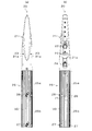
また、上述した各実施形態では、シート状に折り畳まれたラベルLを、マンドレル20に被嵌することによって開口し、下位ショットローラ60によって、マンドレル20に被嵌されたラベルLを周方向に回転させながら下方側に送出しているので、筒状のラベルLが径方向外側に広がって、マンドレル20から飛び出したラベルLの下端部側が先すぼみしにくいが、図11及び図12に示すラベル被嵌装置1aのように、マンドレル20におけるラベル整形部25(下半部25b)の下端部に、ボトル容器Bの搬送方向に延びる、ボトル容器Bの頭部が通過可能な溝部28を形成しておくと、ボトル容器Bがマンドレル20の直下を通過する際は、ボトル容器Bの小径の頭部が溝部28内に入り込んだ状態となるので、ボトル容器Bがマンドレル20の直下を通過するときは、マンドレル20(ラベル整形部25)の下端とボトル容器Bの大径の胴部とが接近した状態となり、マンドレル20から飛び出したラベルLが全く先すぼみしない状態で、ボトル容器Bの胴部に被嵌され始めるので、ラベルLをより確実にボトル容器Bに被嵌することができる。
Further, in each of the above-described embodiments, the label L folded in a sheet shape is opened by being fitted on the
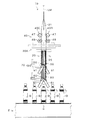
また、上述した実施形態では、マンドレル20の上流側にギロチン方式の基材切断ユニット30を配設しているが、これに限定されるものではなく、例えば、図13及び図14に示すラベル被嵌装置1bのように、マンドレル20によって開口されたラベル形成基材LMを所定長に切断するサークルカッタ30Aを、マンドレル20を取り囲むように配設することも可能である。
In the above-described embodiment, the guillotine-type
このラベル被嵌装置1bでは、上述したラベル被嵌装置1に搭載された、ラベルLをベルト搬送するラベル移送手段40に替えて、上下2個のローラ47、48からなるローラユニット40C、40Dを備えたラベル移送手段40が採用されており、切断位置からラベル形成基材LMの下端までの距離がラベルLの長さと同じになるように、ラベル移送手段40によってラベル形成基材LMを送出した状態で、ラベル形成基材LMの下端と上位ショットローラ50との間に僅かな間隔(例えば、5mm程度)が形成されるように、上位ショットローラ50の高さ位置が設定されている。
In this label
このラベル被嵌装置1bでは、以下のようにしてラベルLが上位ショットローラ50に引き渡される。先ず、ラベル形成基材LMの下端から切断位置までの距離がラベルLの長さと同じになるように、ラベル移送手段40がラベル形成基材LMを所定量だけ送出した後にその送出動作を停止し、続いて、サークルカッタ30Aによって、ラベル形成基材LMからラベルLが切り離される。その後、ラベル移送手段40がラベル形成基材LMを僅かに送出することで、切り離されたラベルLがラベル形成基材LMによって下方側に僅かに押し出され、切断後のラベル移送手段40の送出動作の開始と同時に回転駆動を開始した上位ショットローラ50に把持され、ラベルLの受け渡しが完了する。なお、ラベルLを受け取った上位ショットローラ50は回転を停止して、その後の被嵌タイミングまでラベルLを把持した状態で待機することになる。
In this label
また、上述した各実施形態では、上位ショットローラ50及び下位ショットローラ60をマンドレル20の軸芯に対して60度傾斜させているが、これに限定されるものではない。上位ショットローラ50及び下位ショットローラ60の傾斜角度は、5〜85度程度で設定することができるが、送出速度を得ながら、遠心力を得るためには、30〜70度が好ましく、45〜70度がより好ましい。
In each of the above-described embodiments, the
また、上述した各実施形態では、上位ショットローラ50及び下位ショットローラ60の双方の傾斜角度を同一角度に設定しているが、これに限定されるものではなく、上位ショットローラ50及び下位ショットローラ60で傾斜角度を変えることも可能である。ただし、上位ショットローラ50及び下位ショットローラ60の傾斜角度を同一角度に設定すると共に、上位ショットローラ50から下位ショットローラ60にラベルLを受け渡す際の上位ショットローラ50及び下位ショットローラ60の周速を同一速度に設定しておくと、上位ショットローラ50から下位ショットローラ60へのラベルLの受け渡しを円滑かつ確実に行うことができることは言うまでもない。
In the above-described embodiments, the inclination angles of both the
また、上述した各実施形態では、上位ショットローラ50及び下位ショットローラ60の双方をマンドレル20の軸芯に対して傾斜させているが、これに限定されるものではなく、上位ショットローラ50については、全く傾斜させない状態、即ち、上位ショットローラ50の回転軸とマンドレル20の軸芯とが90度になる状態であってもよい。
Further, in each of the above-described embodiments, both the
また、上述した各実施形態では、同一径の上位ショットローラ50及び下位ショットローラ60を使用しているが、これに限定されるものではなく、下位ショットローラの周速を上げるために、下位ショットローラ60の径を上位ショットローラ50の径より大きくしてもよい。
In each of the above-described embodiments, the
また、上述した各実施形態では、下位ショットローラ60がマンドレル20の下端位置に配設されているが、下位ショットローラ60の配設位置は、マンドレル20の下方位置であればよく、マンドレル20の下端位置に限定されるものではない。
Further, in each of the above-described embodiments, the
また、マンドレルは、全体が剛性のある金属体等によって形成されている必要はなく、例えば、上述した実施形態におけるラベル整形部25の下端に、垂下する板バネを連設し、下位ショットローラがこの板バネとの間にラベルを挟み込む構成を採用する場合は、その板バネもマンドレルの構成要素に含まれる。
Further, the mandrel does not need to be entirely formed of a rigid metal body or the like. For example, a hanging plate spring is continuously provided at the lower end of the
また、上述した実施形態では、長尺のラベル形成基材LMからラベルLを切り離して、ボトル容器Bの胴部に被嵌するラベル被嵌装置1、1a、1bについて説明したが、これに限定されるものではなく、本発明のフィルム被嵌装置は、例えば、容器の口部に筒状のキャップシールを被嵌するキャップシール被嵌装置等、シート状に折り畳まれた筒状フィルムを開口しながら、容器等の被嵌体に被嵌する種々の装置に適用することができる。
Moreover, in embodiment mentioned above, although the label L was cut | disconnected from the elongate label formation base material LM, and the label
シュリンクラベルやキャップシール等の筒状フィルムを容器等の被嵌体に被嵌する装置として利用することができる。 The present invention can be used as a device for fitting a tubular film such as a shrink label or a cap seal to a fitting body such as a container.
1、1a、1b ラベル被嵌装置(フィルム被嵌装置)
1A ラベル制御装置
2 ボトル搬送装置
2A 容器搬送制御装置
2a コンベア
2b コンベアモータ
2c 容器ピッチ切り装置
2d 容器ピッチ切りモータ
10 基材送出ユニット
10a ピッチ送りモータ
11 駆動ローラ
12 従動ローラ
20 マンドレル
21 ラベル開口部
21a 窪み部
22 上位ローラ
23 中位ローラ
24 下位ローラ
25 ラベル整形部
25a 上半部
25b 下半部
26 ローラ
27 ローラ
28 溝部
30 基材切断ユニット
30A サークルカッタ
30a 可動刃モータ
31 固定刃
32 可動刃
40 ラベル移送手段
40a フィードベルトモータ
40A、40B フィードベルトユニット
40C、40D ローラユニット
41 駆動プーリ
42、43、44、45 従動プーリ
46 フィードベルト
47、48 ローラ
50 上位ショットローラ
51 ショットローラモータ
60 下位ショットローラ
61 ショットローラモータ
70 ラベル検出センサ
71 反射鏡
72 ボトル検出センサ
73 反射鏡
81、82 インバータ
83 操作表示装置
84、85、86、87a、87b サーボアンプ
88、89 センサーアンプ
B ボトル容器(被嵌体)
L ラベル(筒状フィルム)
LM ラベル形成基材
1, 1a, 1b Label fitting device (film fitting device)
DESCRIPTION OF
L label (tubular film)
LM label forming substrate
Claims (5)
長尺フィルムを所定長の筒状フィルムにカッタにより切断するフィルム切断手段と、
前記フィルム切断手段と同期を取りながら、筒状フィルムまたは長尺フィルムを下方側に移送するフィルム移送手段と、
前記フィルム切断手段及び前記フィルム移送手段の下方側に配設され、マンドレルに被嵌された筒状フィルムを、マンドレルとの間に挟み込んだ待機状態から、被嵌体の通過タイミングに合わせて所定の送出速度で下方側に送出する動作を行う間欠回転する上位ショットローラと、
前記上位ショットローラによって下方側に送出された筒状フィルムをマンドレルとの間に常時挟み込める状態で配置され、上位ショットローラによって下方側に所定の送出速度で送出された筒状フィルムをマンドレルとの間に挟み込むことによって受け取り連続して下方側に送出することで、マンドレルの直下を通過する被嵌体に筒状フィルムを被嵌する動作を行う連続回転する下位ショットローラとを備え、
前記上位ショットローラによる筒状フィルムの挟込位置と、下位ショットローラによる筒状フィルムの挟込位置との間隔が、筒状フィルムの長さより大きく設定されており、
前記下位ショットローラは、その回転軸が前記マンドレルの軸芯に対して傾いた状態で配設されており、筒状フィルムを前記マンドレルとの間に挟み込んでいるときは、筒状フィルム送出方向の周速に換算した送出方向換算周速が予め設定された被嵌速度に対応する回転速度で定速回転していることを特徴とするフィルム被嵌装置。 The cylindrical film fitted on the mandrel is sequentially sent downward while the cylindrical film of a predetermined length formed by sequentially cutting the cylindrical long film is opened by fitting on the mandrel. In the film fitting apparatus adapted to fit the tubular film to the fitted body passing directly under the mandrel,
Film cutting means for cutting a long film into a cylindrical film of a predetermined length by a cutter;
Film transfer means for transferring a cylindrical film or a long film downward while synchronizing with the film cutting means;
The cylindrical film disposed below the film cutting means and the film transporting means and fitted on the mandrel is placed in a predetermined state in accordance with the passing timing of the fitted body from the standby state sandwiched between the film and the mandrel . A high-order shot roller that rotates intermittently to perform the operation of sending downward at the delivery speed ;
The cylindrical film sent to the lower side by the upper shot roller is arranged so as to be always sandwiched between the mandrel, and the cylindrical film sent to the lower side by the upper shot roller at a predetermined feeding speed is arranged with the mandrel. The lower shot roller that rotates continuously and performs the operation of fitting the tubular film to the fitting body that passes directly under the mandrel by receiving and continuously sending out by sandwiching in between,
The interval between the sandwiching position of the tubular film by the upper shot roller and the sandwiching position of the tubular film by the lower shot roller is set larger than the length of the tubular film,
The lower shot roller is disposed in a state in which the rotation shaft is inclined with respect to the axis of the mandrel. When the tubular film is sandwiched between the mandrel and the lower shot roller, A film-covering device, characterized in that a sending direction-converted peripheral speed converted to a peripheral speed rotates at a constant speed at a rotational speed corresponding to a preset covering speed.
長尺フィルムを所定長の筒状フィルムにカッタにより切断するフィルム切断手段と、
前記フィルム切断手段と同期を取りながら、筒状フィルムまたは長尺フィルムを下方側に移送するフィルム移送手段と、
前記フィルム切断手段及び前記フィルム移送手段の下方側に配設され、マンドレルに被嵌された筒状フィルムを、マンドレルとの間に挟み込んだ待機状態から、被嵌体の通過タイミングに合わせて所定の送出速度で下方側に送出する動作を行う間欠回転する上位ショットローラと、
前記上位ショットローラによって下方側に送出された筒状フィルムをマンドレルとの間に常時挟み込める状態で配置され、上位ショットローラによって下方側に所定の送出速度で送出された筒状フィルムをマンドレルとの間に挟み込むことによって受け取り連続して下方側に送出することで、マンドレルの直下を通過する被嵌体に筒状フィルムを被嵌する動作を行う連続回転する下位ショットローラとを備え、
下位ショットローラは、その回転軸がマンドレルの軸芯に対して傾いた状態で配設されており、筒状フィルムを上位ショットローラから受け取る時点では、上位ショットローラの筒状フィルム送出方向の周速に換算した送出方向換算周速と下位ショットローラの筒状フィルム送出方向の周速に換算した送出方向換算周速とが略一致しており、下位ショットローラは、受け取った筒状フィルムが上位ショットローラから離れた後に増速するようになっていることを特徴とするフィルム被嵌装置。 The cylindrical film fitted on the mandrel is sequentially sent downward while the cylindrical film of a predetermined length formed by sequentially cutting the cylindrical long film is opened by fitting on the mandrel. In the film fitting apparatus adapted to fit the tubular film to the fitted body passing directly under the mandrel,
Film cutting means for cutting a long film into a cylindrical film of a predetermined length by a cutter;
Film transfer means for transferring a cylindrical film or a long film downward while synchronizing with the film cutting means;
The cylindrical film disposed below the film cutting means and the film transporting means and fitted on the mandrel is placed in a predetermined state in accordance with the passing timing of the fitted body from the standby state sandwiched between the film and the mandrel . A high-order shot roller that rotates intermittently to perform the operation of sending downward at the delivery speed ;
The cylindrical film sent to the lower side by the upper shot roller is arranged so as to be always sandwiched between the mandrel, and the cylindrical film sent to the lower side by the upper shot roller at a predetermined feeding speed is arranged with the mandrel. The lower shot roller that rotates continuously and performs the operation of fitting the tubular film to the fitting body that passes directly under the mandrel by receiving and continuously sending out by sandwiching in between,
The lower shot roller is disposed with its rotation axis inclined with respect to the mandrel axis, and when the cylindrical film is received from the upper shot roller, the peripheral speed of the upper shot roller in the cylindrical film feeding direction is The peripheral speed in the feed direction converted to is substantially equal to the peripheral speed in the feed direction converted to the peripheral speed in the cylindrical film feed direction of the lower shot roller. A film fitting apparatus characterized in that the speed is increased after being separated from a roller.
前記マンドレルの下端部には、被嵌体の搬送方向に延びる溝部が形成されており、
被嵌体がマンドレルの直下を通過する際は、被嵌体の小径の頭部が前記溝部内を通過するようになっている請求項1、2、3または4に記載のフィルム被嵌装置。 The to-be-inserted body has a smaller head than the trunk,
At the lower end of the mandrel, a groove is formed that extends in the conveying direction of the fit object,
The film fitting apparatus according to claim 1, 2, 3 or 4, wherein when the fitted body passes immediately below the mandrel, a small-diameter head of the fitted body passes through the groove portion.
Priority Applications (3)
| Application Number | Priority Date | Filing Date | Title |
|---|---|---|---|
| JP2012014899A JP5957230B2 (en) | 2012-01-27 | 2012-01-27 | Film fitting device |
| US13/673,184 US9278773B2 (en) | 2011-11-14 | 2012-11-09 | Film-fitting device |
| PCT/JP2012/079879 WO2013080818A1 (en) | 2011-11-14 | 2012-11-13 | Film-fitting device |
Applications Claiming Priority (1)
| Application Number | Priority Date | Filing Date | Title |
|---|---|---|---|
| JP2012014899A JP5957230B2 (en) | 2012-01-27 | 2012-01-27 | Film fitting device |
Publications (2)
| Publication Number | Publication Date |
|---|---|
| JP2013154893A JP2013154893A (en) | 2013-08-15 |
| JP5957230B2 true JP5957230B2 (en) | 2016-07-27 |
Family
ID=49050507
Family Applications (1)
| Application Number | Title | Priority Date | Filing Date |
|---|---|---|---|
| JP2012014899A Expired - Fee Related JP5957230B2 (en) | 2011-11-14 | 2012-01-27 | Film fitting device |
Country Status (1)
| Country | Link |
|---|---|
| JP (1) | JP5957230B2 (en) |
Families Citing this family (1)
| Publication number | Priority date | Publication date | Assignee | Title |
|---|---|---|---|---|
| JP6411205B2 (en) * | 2014-12-24 | 2018-10-24 | ケーユーシステム株式会社 | Shrink label mounting machine and manufacturing method of shrink label |
Family Cites Families (3)
| Publication number | Priority date | Publication date | Assignee | Title |
|---|---|---|---|---|
| JP4651222B2 (en) * | 2001-05-10 | 2011-03-16 | 株式会社フジシールインターナショナル | Cylindrical film delivery device |
| NL1033245C2 (en) * | 2007-01-17 | 2008-07-18 | Fuji Seal Europe Bv | Device for manufacturing sleeve-shaped foil envelopes from a strip of sleeve-like foil material. |
| JP5616651B2 (en) * | 2010-02-23 | 2014-10-29 | 株式会社フジシールインターナショナル | Film fitting device |
-
2012
- 2012-01-27 JP JP2012014899A patent/JP5957230B2/en not_active Expired - Fee Related
Also Published As
| Publication number | Publication date |
|---|---|
| JP2013154893A (en) | 2013-08-15 |
Similar Documents
| Publication | Publication Date | Title |
|---|---|---|
| JP6027105B2 (en) | Cylindrical film body fitting apparatus and method | |
| ITMI20101293A1 (en) | CUTTING DRUM AND TRANSFER OF LINERLESS LABELS FROM A CONTINUOUS TAPE TO A MOVING CONTAINER AND EQUIPMENT EQUIPPED WITH SUCH DRUM | |
| US20170233128A1 (en) | Method and device for the application of shrink film sleeve | |
| JP6338789B2 (en) | Apparatus and method for applying drinking straws to package containers | |
| JP6346998B2 (en) | Method of operating a device for applying a drinking straw to a packaging container and device operated by the method | |
| JP6675133B2 (en) | Label sticking device | |
| JP5957230B2 (en) | Film fitting device | |
| KR20050028884A (en) | Changeover device and method for changing over winding of web | |
| JP6028173B2 (en) | Manufacturing apparatus and manufacturing method for cylindrical film body | |
| JP5616651B2 (en) | Film fitting device | |
| JP2018504331A (en) | Method for operating a device for applying a drinking straw to a packaging container and device operated by the method | |
| JP5816569B2 (en) | Film fitting device | |
| JP2013203538A (en) | Web conveyance device that can simultaneously feed webs from a plurality of rolled materials | |
| EP3030487B1 (en) | Device for applying around groups of two or more containers a tape provided on one surface with adhesive without discontinuities | |
| JP5917101B2 (en) | Film fitting device | |
| JP6031726B2 (en) | Container processing device with container supply device | |
| JP5917113B2 (en) | Film fitting device | |
| JP5917100B2 (en) | Film fitting device | |
| JP5917090B2 (en) | Film fitting device | |
| JP2914934B2 (en) | Spiral paper tube manufacturing method and apparatus | |
| JP7018943B2 (en) | Sleeve mounting system and method | |
| JP4908971B2 (en) | Threaded container printing device | |
| JP6131676B2 (en) | Web feeding device and web feeding method | |
| JP3031162B2 (en) | Sleeve winding molding machine | |
| JP7075422B2 (en) | Sheet supply method and sheet supply device |
Legal Events
| Date | Code | Title | Description |
|---|---|---|---|
| A621 | Written request for application examination |
Free format text: JAPANESE INTERMEDIATE CODE: A621 Effective date: 20141203 |
|
| A131 | Notification of reasons for refusal |
Free format text: JAPANESE INTERMEDIATE CODE: A131 Effective date: 20150915 |
|
| A521 | Request for written amendment filed |
Free format text: JAPANESE INTERMEDIATE CODE: A523 Effective date: 20151111 |
|
| TRDD | Decision of grant or rejection written | ||
| A01 | Written decision to grant a patent or to grant a registration (utility model) |
Free format text: JAPANESE INTERMEDIATE CODE: A01 Effective date: 20160524 |
|
| A61 | First payment of annual fees (during grant procedure) |
Free format text: JAPANESE INTERMEDIATE CODE: A61 Effective date: 20160620 |
|
| R150 | Certificate of patent or registration of utility model |
Ref document number: 5957230 Country of ref document: JP Free format text: JAPANESE INTERMEDIATE CODE: R150 |
|
| R250 | Receipt of annual fees |
Free format text: JAPANESE INTERMEDIATE CODE: R250 |
|
| R250 | Receipt of annual fees |
Free format text: JAPANESE INTERMEDIATE CODE: R250 |
|
| R250 | Receipt of annual fees |
Free format text: JAPANESE INTERMEDIATE CODE: R250 |
|
| R250 | Receipt of annual fees |
Free format text: JAPANESE INTERMEDIATE CODE: R250 |
|
| LAPS | Cancellation because of no payment of annual fees |