JP5956756B2 - Video processing apparatus and control method thereof - Google Patents
Video processing apparatus and control method thereof Download PDFInfo
- Publication number
- JP5956756B2 JP5956756B2 JP2012011506A JP2012011506A JP5956756B2 JP 5956756 B2 JP5956756 B2 JP 5956756B2 JP 2012011506 A JP2012011506 A JP 2012011506A JP 2012011506 A JP2012011506 A JP 2012011506A JP 5956756 B2 JP5956756 B2 JP 5956756B2
- Authority
- JP
- Japan
- Prior art keywords
- light source
- subject
- image data
- background image
- acquired
- Prior art date
- Legal status (The legal status is an assumption and is not a legal conclusion. Google has not performed a legal analysis and makes no representation as to the accuracy of the status listed.)
- Active
Links
- 238000000034 method Methods 0.000 title claims description 62
- 239000002131 composite material Substances 0.000 claims description 42
- 230000000694 effects Effects 0.000 claims description 34
- 230000015572 biosynthetic process Effects 0.000 claims description 29
- 238000003786 synthesis reaction Methods 0.000 claims description 29
- 230000002194 synthesizing effect Effects 0.000 claims description 8
- 238000003384 imaging method Methods 0.000 claims description 5
- 239000000203 mixture Substances 0.000 description 9
- 238000010586 diagram Methods 0.000 description 4
- 238000002360 preparation method Methods 0.000 description 4
- 238000007796 conventional method Methods 0.000 description 2
- 230000006870 function Effects 0.000 description 2
- 238000001514 detection method Methods 0.000 description 1
- 238000001035 drying Methods 0.000 description 1
- 230000005484 gravity Effects 0.000 description 1
- 238000005286 illumination Methods 0.000 description 1
- 230000010365 information processing Effects 0.000 description 1
- 239000004973 liquid crystal related substance Substances 0.000 description 1
Images


Description
本発明は、映像処理技術に関し、特に画像合成の際、背景用画像および合成位置に応じて前景用画像にライティング効果を施す映像処理技術に関する。 The present invention relates to a video processing technique, and more particularly, to a video processing technique for applying a lighting effect to a foreground image in accordance with a background image and a synthesis position during image synthesis.
前景用画像から被写体を切り出し背景用へ合成することは、映像編集において良く行われている。たとえばブルーバックで撮影した映像から被写体をクロマキーで切り出した後、異なる映像に合成するなどがその典型である。その際、合成後の映像を自然なものとするためには、背景用映像のライティングと前景用映像のライティングが一致している必要がある。ライティングを一致させるために、CGを用いて実写画像にライティング効果を施すことが行われている。 It is common in video editing to cut out a subject from a foreground image and combine it with a background image. For example, a typical example is that a subject is cut out with a chroma key from a video shot with a blue background and then combined with a different video. At that time, in order to make the synthesized video natural, it is necessary that the lighting of the background video and the lighting of the foreground video match. In order to match the lighting, a lighting effect is applied to a real image using CG.
CGを用いたライティングとして、ライティング環境を3Dモデル化し、光の経路を計算するレイトレーシングやラジオシティを用いてライティングすることが良く行われている。 As lighting using CG, lighting is often performed using a ray tracing or radiosity that makes a lighting environment a 3D model and calculates a light path.
また、背景用画像を撮影した現場の全周囲画像を撮影し、撮影した全周囲画像を光源画像として用いライティング効果を施す、イメージベースドライティングが良く行われている(非特許文献1、非特許文献2)。また、遠方の光源をイメージベースドライティングで行い、近傍の光源については3Dモデルを利用し、ライティング効果を施すことも行われている。(非特許文献3)
In addition, image-based lighting is often performed in which a background image of a background image is captured and a lighting effect is applied using the captured environment image as a light source image (Non-Patent
上記従来件のイメージベースドライティングを用いた手法では、合成位置を変更した場合、合成位置に応じた全周囲画像をあらかじめ用意しておく必要がある。これは合成位置が変化すると、近傍光源と合成位置との位置関係が大きく変化し、ライティングが大きく変化してしまうためである。合成位置に応じた全周囲画像を用いない場合、不自然なライティング効果が施されてしまう。あらかじめ合成する位置が決まっていれば、有限個の全周囲画像を用意すればよい。合成位置は無数にあるため、合成位置に応じたすべての全周囲画像をあらかじめ用意することは不可能である。 In the conventional method using image-based lighting, when the synthesis position is changed, it is necessary to prepare an all-around image corresponding to the synthesis position in advance. This is because when the composition position changes, the positional relationship between the neighboring light source and the composition position changes greatly, and the lighting changes greatly. If an all-around image corresponding to the synthesis position is not used, an unnatural lighting effect is applied. If the positions to be combined are determined in advance, a finite number of all-around images may be prepared. Since there are an infinite number of combining positions, it is impossible to prepare all the surrounding images according to the combining positions in advance.
また、上記従来件のレイトレーシングやラジオシティを用いた手法では、背景用画像を撮影した現場の照明環境を手作業で3Dモデル化しなければならず手間がかかってしまう。また、レイトレーシングやラジオシティは、光線の経路を計算してライティングを行うが、より自然なライティングを実現されるためには、光線の経路が何度も分岐するため計算量が多くなってしまう。 In the conventional method using ray tracing or radiosity, the lighting environment in the field where the background image is taken must be manually modeled as a 3D model, which is troublesome. Ray tracing and radiosity perform lighting by calculating ray paths, but in order to achieve more natural lighting, the ray paths branch many times and the amount of calculations increases. .
本発明は、上記問題を解決し、容易に合成位置に応じたライティング効果を施すことを可能とする技術を提供しようとするものである。 The present invention seeks to provide a technique that solves the above-described problems and that can easily provide a lighting effect according to a synthesis position.
この課題を解決するため、例えば本発明の映像処理装置は以下の構成を備える。すなわち、
前景画像データにライティング効果を施し、背景画像データに合成を行う映像処理装置であって、
前記背景画像データと、当該背景画像データを撮像した際の撮像装置に対する少なくとも1つの光源の位置を表す光源情報と、前記前景画像データとしての被写体の動画像データを記憶する記憶手段と、
前記背景画像データにおける、前記被写体の初期の合成位置を取得する合成位置取得手段と、
取得した前記初期の合成位置を前記動画像データにおける前記被写体の初期配置位置とする、前記被写体と前記背景画像データとの合成フレームを順に生成することで、合成動画像データを生成する合成動画像生成手段とを備え、
前記合成動画像生成手段は、
前記合成フレームを生成する毎に、前記背景画像データにおける前記被写体の前記合成位置の空間座標を取得する空間座標取得手段と、
該空間座標取得手段で取得した前記被写体の前記空間座標と、前記記憶手段から取得した前記光源情報が示す各光源との距離を算出する算出手段と、
前記記憶手段から取得した前記光源情報が示す光源のうち、前記算出手段で算出した距離が予め設定された閾値を超える光源の位置は変更せず、前記算出手段で算出した距離が前記閾値以下となる光源については前記被写体から見た光源の位置を求め、前記取得した光源情報における該当する光源の位置を、前記求めた位置により変更する変更手段と、
該変更手段による変更処理後の光源情報が示す各光源の位置を用いて、前記被写体にライティング効果を施すライティング手段と、
該ライティング手段によるライティング効果が施された前記被写体を、前記背景画像データにおける前記被写体の配置位置に合成することで前記合成フレームを生成する合成手段とを含むことを特徴とする。
In order to solve this problem, for example, a video processing apparatus of the present invention has the following configuration. That is,
Applying lighting effects to the foreground picture image data, an image processing apparatus for synthesizing the background image data,
Storage means for storing the background image data, light source information representing a position of at least one light source with respect to the imaging device when the background image data is captured, and moving image data of the subject as the foreground image data;
A composite position acquisition means for acquiring an initial composite position of the subject in the background image data ;
The synthesized moving image that generates the synthesized moving image data by sequentially generating a synthesized frame of the subject and the background image data, in which the obtained initial synthesized position is the initial arrangement position of the subject in the moving image data. Generating means,
The synthesized moving image generating means
Spatial coordinate acquisition means for acquiring the spatial coordinates of the composite position of the subject in the background image data each time the composite frame is generated ;
Calculation means for calculating a distance between the spatial coordinates of the subject acquired by the spatial coordinate acquisition means and each light source indicated by the light source information acquired from the storage means ;
Among the light sources indicated by the light source information acquired from the storage unit, the position of the light source whose distance calculated by the calculation unit exceeds a preset threshold is not changed, and the distance calculated by the calculation unit is equal to or less than the threshold. For the light source to be obtained, the position of the light source viewed from the subject, the changing means for changing the position of the corresponding light source in the acquired light source information according to the obtained position ;
Lighting means for applying a lighting effect to the subject using the position of each light source indicated by the light source information after the change processing by the changing means;
The subject lighting effect said writing means has been performed, characterized in that it comprises a synthesizing means for generating the composite frame by synthesizing the arrangement position of the object in the background image data.
本発明によれば、容易に合成位置に応じたライティング効果を前景用画像に施すことができ、映像を合成しても自然な映像とすることができる。 According to the present invention, it is possible to easily apply a lighting effect corresponding to the synthesis position to the foreground image, and to make a natural video even if the video is synthesized.
以下、添付図面に従って本発明に係る実施形態を詳細に説明する。 Hereinafter, embodiments according to the present invention will be described in detail with reference to the accompanying drawings.
[第1の実施形態]
以下、図面を用いて本実施形態について説明する。
[First Embodiment]
Hereinafter, the present embodiment will be described with reference to the drawings.
図1に本実施形態を実現するためのハードウエア構成図を示す。CPU101は、各構成の全ての処理にかかわり、ROM102やRAM103に格納された命令を順に読み込み、解釈し、その結果に従って処理を事項する。また、ROM102とRAM103は、その処理に必要なプログラム、データ、作業領域などをCPU101に提供する。記憶媒体104は、画像データなどを記憶する記憶媒体(もしくはデバイス)であって、例えばハードディスク、CFカード、SDカード、USBメモリ、メモリーカードなどである。入力装置105は、タッチスクリーン、キーボード、マウスなどの入力機器であり、ユーザからの指示を受け取る。出力装置106は、一般的には液晶ディスプレイが広く用いられており、画像や文字の表示を行う。また、タッチパネル機能を有していても良く、その場合は、入力装置105として扱うことも可能である。
FIG. 1 shows a hardware configuration diagram for realizing the present embodiment. The
本実施形態では、上記映像編集装置の一形態としてフォトフレームに適用した例を説明する。 In the present embodiment, an example in which the present invention is applied to a photo frame as an embodiment of the video editing apparatus will be described.
図2は、本実施形態における映像処理装置であるフォトフレームの正面図である。タッチスクリーンディスプレイ201は、画像を表示するためのディスプレイであり、かつ、ユーザの入力を受け取る入力機器である。このタッチスクリーンディスプレイ201は、図1における出力装置106と入力装置105に相当することになり、同時に複数の入力の座標を個々に検出することが可能である。202は、電源ボタンである。
FIG. 2 is a front view of a photo frame which is a video processing apparatus in the present embodiment. The
図3に、本実施形態における映像編集画面で被写体の合成位置を変更した前後のスクリーンショットを示す。301は背景用画像、302は合成されている前景用画像である。記憶媒体104に、背景用画像、前景用画像それぞれが区別されて、多数格納されていて、図示の背景用画像301、前景用画像302はその中からユーザが指定したものである。前景用画像にはα値(透明度)が付加されてあり、所望の被写体が切り抜かれている。本実施形態では、前景用画像302は動画像であり、再生されることにより、被写体が動き、その合成位置が変化する。合成位置の変更に伴い、前景用画像303に、合成位置に応じたライティング効果を施す。尚、本実施形態では、前景用画像が動画像のため合成位置が変化しているが、これは一例であり、これに限るものではない。例えば、ユーザが前景用画像をドラッグすることにより、前景用画像の合成位置を変更してもよい。またはユーザ操作に応じて、前景用画像のスケールを変更や、背景用画像を移動またはスケールを変更するなどしてもよい。
FIG. 3 shows screenshots before and after the subject composition position is changed on the video editing screen in the present embodiment.
図4に本実施形態の装置の機能ブロック図を示している。図示において、401は、前景用画像である。402は、背景用画像である。403は、背景用画像402の各画素の奥行きを表す背景用画像奥行き情報である。奥行き情報は、背景用画像402と同じ解像度の画像形式で、各画素のRGB成分に奥行き情報を記録する。また、背景画像をステレオ画像として撮影し、ステレオマッチング法を用いることにより、背景用画像奥行き情報を生成する。尚、ステレオマッチング法を用いて奥行き情報を生成することは一例であり、これに限るものではない。例えば、背景用画像の直線および消失点を検出し、奥行き情報を推定してもよい。また、ユーザが指定してもよい。404は、背景用画像を撮影した位置から見た光源の位置情報または照度情報を表す光源パラメータである。光源の位置情報は、特開2010−181826号公報などを用いて、背景用画像を撮影した位置の全周囲画像およびその奥行き情報を生成することによって、取得する。光源の照度情報は、背景用画像を撮影した位置の全周囲画像をHDR画像で撮影し、その画像の輝度値を照度情報として取得する。尚、これらは一例であり、これに限るものではない。例えば、光源の位置情報は、ユーザが指定してもよいし、測距センサーを用いて光源までの知情報を取得してもよい。また、光源の照度情報は、ユーザが指定しても良いし、照度計で測定してもよい。
FIG. 4 shows a functional block diagram of the apparatus of the present embodiment. In the drawing, 401 is a foreground image.
図5に光源パラメータのテーブルの一例を示す。501は、各光源を識別するためのIDである。全周囲画像中で一定以上の輝度値がある領域を光源とし、その重心を光源の位置とする。502は、背景画像撮影位置から光源までの距離情報である。単位はメートルである。距離情報が取得できなかった場合は、無限遠に存在するとして「−1」を保持する。503および504は背景画像撮影位置からみた光源の方向で、方位角および仰角である。単位は度である。尚、本実施形態では、全周囲画像で一定上の輝度値を持つ領域を光源の領域とみなしているが、これは一例であり、これに限るものではない。例えば、各画素それぞれを光源として扱ってもよい。また、本実施形態では、光源位置を極座標系で保持しているが、これは一例でありこれに限るものではない。例えば、直交座標系で保持してもよい。
FIG. 5 shows an example of a light source parameter table.
図4の説明に戻る。図示の405は、光の伝搬をあらかじめ算出した結果である。光伝搬事前計算結果である。算出には、先に示した非特許文献1や非特許文献2などを用いて行う。406は、本実施形態における映像編集装置の編集結果である合成画像である。前景用画像401、背景用画像402、背景用画像奥行き情報403、光源パラメータ404、光伝搬事前計算結果405および合成画像406は、記録媒体104に記録される。410は、本実施形態における映像編集装置である。411は、合成位置として背景用画像上の座標を取得する合成位置取得部である。入力装置105を用いてユーザが指定した背景用画像上の座標を合成位置として取得する。また、あらかじめユーザが指定した合成の基準点となる前景用画像上の画素の、背景用画像上の座標を合成位置として取得する。尚、合成の基準点をユーザが指定しているが、これは一例であり、これに限るものではない。例えば、顔検出を行い顔の位置を合成位置の基準としてもよい。また、前景用画像の不透明部分の最下部を合成位置の基準としてもよい。
Returning to the description of FIG. 405 in the figure is the result of calculating the light propagation in advance. It is a light propagation prior calculation result. The calculation is performed using
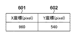
図6に合成位置情報の一例を示す。601は、合成位置の背景用画像上のX座標、602はY座標である。
FIG. 6 shows an example of the combined position information.
引き続き図4に基づき、本実施形態の説明を行う。412は、背景用画像の奥行き情報から生成した空間の座標を、背景用画像上の二次元の座標に投影した投影情報を生成する投影部である。透視投影法を用いて、投影を行う。
Next, the present embodiment will be described with reference to FIG.
図7に投影情報の一例を示す。701は、背景用画像上の二次元の座標である。702はX座標である。703はY座標である。711は、背景用画像の奥行き情報から生成した空間上の座標である。712はX座標である。713はY座標である。714はZ座標である。尚、これは一例であり、これに限るものではない。例えば、背景用画像上の各画素に対応するX座標、Y座標、Z座標をR、G、B情報とし画像情報として保持してもよい。
FIG. 7 shows an example of projection information.
引き続き図4に基づき、本実施形態について説明する。413は、投影部412が生成した投影情報に基づき、合成位置取得部411で取得した背景用画像上の座標に対応する空間座標を取得する、空間座標取得部である。
Next, the present embodiment will be described with reference to FIG.
414は、合成位置の空間座標と光源との距離または合成位置の空間座標から見た光源の照度を算出する光源距離または照度算出部である。詳細は後述する。415は、光源パラメータを変更する光源パラメータ変更手段である。詳細は後述する。416は、光源パラメータ変更部415が変更した光源パラメータに基づき、前景用画像にライティング効果を施すライティング部である。詳細は後述する。尚、ここで前景用画像に、陰影部分を除去する処理を行ってから、ライティング効果を施してもよい。陰影部分の除去は、特開2010−135996号公報などに開示された技術を用いて行う。417は、411が取得した合成位置に、ライティング部416よってライティング効果を施された前景用画像を背景用画像に合成する合成部である。合成部416の合成結果は、記録媒体104および出力装置106へ出力される。
図8に、本実施形態における映像編集装置のCPU101が実行する制御処理手順のフローチャートを示す。映像編集装置が起動されると、記録媒体104からユーザが選択した前景用画像を取得する(S801)。本実施形態では、動画像を取得する。次に、記録媒体104からユーザが選択した背景用画像を取得する(S802)。入力装置105からのユーザ入力から、初期合成位置を取得する(S803)。記録媒体104から、S802で取得した背景用画像に応じた奥行き情報を取得する(S804)。記録媒体104から、S802で取得した背景用画像に応じた光源パラメータのテーブルを取得する(S805)。映像編集処理を開始する(S806)。この映像編集処理の詳細については後述する。編集が完了した画像を記録媒体104へ記録する(S807)。終了操作が行われたか否かを判定する(S808)。終了操作が行われていないと判定した場合(S808)、前景用画像を取得する(S801)。終了操作が行われたと判定した場合(S808)、映像編集装置を終了する。
FIG. 8 shows a flowchart of a control processing procedure executed by the
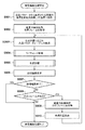
図9に、本実施形態における上記のS806の映像編集処理のフローチャートを示す。映像編集処理が開始されると、S804で取得した背景用画像奥行き情報から生成した空間の座標を、背景用画像上の二次元の座標に投影し、投影情報を生成する(S901)。S801で取得した前景用画像の先頭フレームを取得する(S902)。光源パラメータ変更処理を行う(S903)。光源パラメータ変更処理の詳細は後述する。ライティング処理を行う(S904)。ライティング処理の詳細は後述する。合成処理を行う(S905)。合成処理の詳細は後述する。合成画像を表示装置106へ表示する(S906)。映像編集終了操作が行われたか否か判定する(S907)。終了操作がされたと判定した場合(S907)、映像編集処理を終了する。終了操作がされていないと判定した場合(S907)、前景用画像として用いた動画像に次のフレームがあるか否か判定する(S908)。次のフレームが有ると判定された場合(S908)、前景用画像として動画像の次のフレーム画像を取得する(S909)。前景のあらかじめ定めた画素を検出し、前のフレームとの位置の変化だけ、合成位置を変更する(S910)。次のフレームが無いと判定された場合(S908)、映像編集処理を終了する。 FIG. 9 shows a flowchart of the video editing process of S806 in the present embodiment. When the video editing process is started, the coordinates of the space generated from the background image depth information acquired in S804 are projected onto the two-dimensional coordinates on the background image to generate projection information (S901). The first frame of the foreground image acquired in S801 is acquired (S902). A light source parameter change process is performed (S903). Details of the light source parameter changing process will be described later. Writing processing is performed (S904). Details of the lighting process will be described later. A synthesis process is performed (S905). Details of the synthesis process will be described later. The composite image is displayed on the display device 106 (S906). It is determined whether a video editing end operation has been performed (S907). If it is determined that the end operation has been performed (S907), the video editing process is ended. If it is determined that the ending operation has not been performed (S907), it is determined whether or not there is a next frame in the moving image used as the foreground image (S908). If it is determined that there is a next frame (S908), the next frame image of the moving image is acquired as the foreground image (S909). A predetermined pixel in the foreground is detected, and the composition position is changed only by a change in position with the previous frame (S910). If it is determined that there is no next frame (S908), the video editing process is terminated.
図10に、本実施形態における光源パラメータ変更処理903のフローチャートを示す。光源パラメータ変更処理が開始されると、S901で生成した投影情報から合成位置の空間座標を取得する(S1001)。S805で取得した光源パラメータテーブルから光源パラメータを取得する(S1002)。S1001で取得した合成位置の空間座標およびS1002で取得した光源パラメータから、光源の距離を式1、式2に基づき算出する(S1003)。
FIG. 10 shows a flowchart of the light source
光源パラメータの距離情報502をR、方位角503をθ、仰角504をφとする。合成位置の空間座標のx座標をXc、y座標をYc、z座標をZcとする。算出する距離をRlとする。
Xl=R・cos(θ)cos(φ)−Xc
Yl=R・sin(θ)cos(φ)−Yc
Zl=R・sin(θ)−Zc …(1)
Rl={Xl 2+Yl 2+Zl 2}1/2 …(2)
The
X 1 = R · cos (θ) cos (φ) −X c
Y l = R · sin (θ) cos (φ) −Y c
Z l = R · sin (θ) −Z c (1)
R l = {X l 2 +
そして、S1004にて、S1003で算出した値が、閾値以下か否かを判定する。閾値以下と判定された時のみ、S1001で取得した合成位置の空間座標およびS1002で取得した光源パラメータに基づき、光源パラメータ変更処理を行う(S1005)。パラメータの変更は、式(3)、式(4)に基づき行う。 In S1004, it is determined whether or not the value calculated in S1003 is equal to or less than a threshold value. Only when it is determined that the threshold value is equal to or less than the threshold value, the light source parameter changing process is performed based on the spatial coordinates of the combined position acquired in S1001 and the light source parameter acquired in S1002 (S1005). The parameter is changed based on the equations (3) and (4).
光源パラメータの距離情報502をR、方位角503をθ、仰角504をφとする。合成位置の空間座標のx座標をXc、y座標をYc、z座標をZcとする。光源パラメータ変更後の光源のx座標をXl、y座標をYl、z座標をZlとする。光源パラメータ変更後の距離情報502をRl、方位角503をθl、仰角504をφlとする。
Xl=R・cos(θ)cos(φ)−Xc
Yl=R・sin(θ)cos(φ)−Yc
Zl=R・sin(θ)−Zc …(3)
Rl={Xl 2+Yl 2+Zl 2}1/2
θl=arccos{Xl/{(Xl 2+Yl 2)1/2}}
φl=arcsin{Zl/{(Xl 2+Yl 2)1/2}} …(4)
The
X 1 = R · cos (θ) cos (φ) −X c
Y l = R · sin (θ) cos (φ) −Y c
Z l = R · sin (θ) −Z c (3)
R l = {X l 2 +
θ l = arccos {X l / {(X l 2 + Y l 2 ) 1/2 }}
φ l = arcsin {Z l / {(X l 2 + Y l 2 ) 1/2 }} (4)
すべての光源パラメータを処理したか否かを判定する(S1006)。すべての光源パラメータを処理していないと判定された場合(S1006)。次の光源パラメータを取得する(S1001)。すべての光源パラメータを処理した場合(S1006)、光源パラメータ変更処理を終了する。尚、この光源パラメータ変更処理は一例であり、これに限るものではない。例えば、光源パラメータを全周囲画像およびその奥行き情報を画像情報として保持する。光源ごとに画像を分割する。合成位置から見た各光源の方向が一致するように、分割した各光源の画像に回転、平行移動、拡大および縮小処理を行う。このように処理してもよい。 It is determined whether all the light source parameters have been processed (S1006). When it is determined that all the light source parameters are not processed (S1006). The next light source parameter is acquired (S1001). When all the light source parameters have been processed (S1006), the light source parameter changing process is terminated. The light source parameter changing process is an example, and the present invention is not limited to this. For example, the light source parameter is held as an all-around image and its depth information as image information. Divide the image for each light source. Rotation, parallel movement, enlargement, and reduction processing are performed on the divided images of the light sources so that the directions of the light sources viewed from the combination position coincide. You may process in this way.
図11に、本実施形態における、ライティング処理S904のフローチャートを示す。前景用画像の形状に基づき、事前に計算していた自己遮蔽情報や遮蔽情報などの光伝搬情報を取得する(S1101)。前景用画像の形状は、ステレオ撮影した前景用画像しておき、ステレオマッチングを用いて取得した奥行き情報に基づき推定する。S903で変更処理を行った光源パラメータのテーブルを取得する(S1102)。取得した光源パラメータおよび光伝搬情報に基づき、各画素の放射輝度を算出する(S1103)。算出した放射輝度に基づき、前景用画像の各画素の色を変更する(S1104)。尚、光伝搬の算出および放射輝度の算出は、非特許文献1や非特許文献2などを用いて行う。
FIG. 11 shows a flowchart of the lighting process S904 in the present embodiment. Based on the shape of the foreground image, light propagation information such as self-shielding information and shielding information calculated in advance is acquired (S1101). The shape of the foreground image is estimated based on depth information obtained using stereo matching by taking a stereo image of the foreground. A table of light source parameters subjected to the change process in S903 is acquired (S1102). Based on the acquired light source parameter and light propagation information, the radiance of each pixel is calculated (S1103). Based on the calculated radiance, the color of each pixel of the foreground image is changed (S1104). Note that calculation of light propagation and calculation of radiance are performed using
図12に、本実施形態における、合成処理S905のフローチャートを示す。前景用画像の画素を取得する(S1201)。取得した画素が合成される位置の背景用画素を取得する(S1202)。前景用画像の画素値をF、前景用画像のα値をα、背景用画像の画素値をB、合成後の画素値Cとすると、式(5)に基づき合成処理を行う(S1203)。
C=Fα+B(1−α) …(5)
FIG. 12 shows a flowchart of the synthesis process S905 in the present embodiment. Pixels of the foreground image are acquired (S1201). A background pixel at a position where the acquired pixel is synthesized is acquired (S1202). Assuming that the pixel value of the foreground image is F, the α value of the foreground image is α, the pixel value of the background image is B, and the pixel value C after the combination is combined, the combining process is performed based on Expression (5) (S1203).
C = Fα + B (1−α) (5)
このように構成し処理することにより、容易に合成位置に応じたライティング効果を前景用画像に施すことができ、映像を合成しても自然な映像とした合成画像406として生成される。後は、ユーザの指定により、この合成画像406を再生処理を行うことになる。
By configuring and processing in this way, a lighting effect corresponding to the synthesis position can be easily applied to the foreground image, and even if the video is synthesized, the
[第2の実施形態]
次の第2の実施形態を説明する。尚、第1の実施形態に準ずる箇所は、説明を割愛する。本第2の実施形態では、前景用画像として静止画を利用し、ユーザがドラッグ操作など行い所望の合成位置を指定する。その際、合成位置の変化に応じて、前景用画像には、ライティング効果が施される。また、光源の強度に基づき、光源パラメータを変更するか否かを判定する。
[Second Embodiment]
The following second embodiment will be described. In addition, the description according to the first embodiment is omitted. In the second embodiment, a still image is used as the foreground image, and the user designates a desired synthesis position by performing a drag operation or the like. At that time, a lighting effect is applied to the foreground image according to the change in the composition position. Further, it is determined whether or not to change the light source parameter based on the intensity of the light source.
図13に、第2の実施形態における光源パラメータの一例を示す。第1の実施形態に準ずる箇所は説明を割愛する。1301は、光源の照度情報である。本実施形態では、式(6)を用いて、全周囲画像の各画素のRGB値からXYZ値に変換し、Yの値を照度として取得する。
X=0.412453R+0.35758G+0.180423B
Y=0.212671R+0.71516G+0.072169B
Z=0.019334R+0.119193G+0.950227B …(6)
尚、これは一例であり、これに限るものではない。例えば、HSVに変換しVの値を照度としてもよい。
FIG. 13 shows an example of a light source parameter in the second embodiment. The description according to the first embodiment is omitted.
X = 0.412453R + 0.35758G + 0.180423B
Y = 0.212671R + 0.71516G + 0.072169B
Z = 0.019334R + 0.119193G + 0.950227B (6)
This is an example, and the present invention is not limited to this. For example, it may be converted into HSV and the value of V may be illuminance.
図14に、第2の実施形態における映像編集装置のフローチャートを示す。第1の実施形態に準ずる箇所は説明を割愛する。記録媒体104から、前景用画像としてユーザが選択した静止画を取得する(S1401)。 FIG. 14 shows a flowchart of the video editing apparatus according to the second embodiment. The description according to the first embodiment is omitted. A still image selected by the user as a foreground image is acquired from the recording medium 104 (S1401).
図15に、第2の実施形態における、映像編集処理S806のフローチャートを示す。第1の実施形態に準ずる箇所は説明を割愛する。入力装置105からのユーザ入力から、合成位置を取得する(S1501)。 FIG. 15 shows a flowchart of the video editing process S806 in the second embodiment. The description according to the first embodiment is omitted. The composite position is acquired from the user input from the input device 105 (S1501).
図16に、第2の実施形態における、光源パラメータ変更処理S903のフローチャートを示す。第1の実施形態に準ずる箇所は説明を割愛する。式(1)、式(2)を用いて、S906で取得した合成位置の空間座標から光源まで距離を算出する。算出した距離および光源パラメータから、合成位置の空間座標から見た照度を、式(7)を用いて算出する(S1601)。光源パラメータの照度をE、算出する照度をElとする。
El=E・(R・R)/(Rl・Rl) …(7)
尚、これは一例であり、これに限るものではない。光源パラメータの照度Eを判定基準として用いてもよい。算出した照度があらかじめ定めた閾値以上か否かを判定する(S1602)。算出した照度が閾値以上の場合(S1602)、光源パラメータを変更する(S1005)。尚、S1005では、光源パラメータの位置情報を変更しているが、これは一例であり、これに限るものではない。光源パラメータの照度情報を式(5)に基づき変更してもよい。算出した照度が閾値未満の場合(S1602)、すべての光源パラメータを処理したか判定する(S1006)。
FIG. 16 shows a flowchart of the light source parameter change processing S903 in the second embodiment. The description according to the first embodiment is omitted. Using formulas (1) and (2), the distance to the light source is calculated from the spatial coordinates of the composite position acquired in step S906. From the calculated distance and the light source parameter, the illuminance viewed from the spatial coordinates of the combined position is calculated using Equation (7) (S1601). The illuminance of the light source parameter is E, and the calculated illuminance is El .
E l = E · (R · R) / (R l · R l) ... (7)
This is an example, and the present invention is not limited to this. The illuminance E of the light source parameter may be used as a criterion. It is determined whether the calculated illuminance is greater than or equal to a predetermined threshold (S1602). If the calculated illuminance is greater than or equal to the threshold (S1602), the light source parameter is changed (S1005). In S1005, the position information of the light source parameter is changed, but this is an example, and the present invention is not limited to this. You may change the illumination intensity information of a light source parameter based on Formula (5). If the calculated illuminance is less than the threshold (S1602), it is determined whether all light source parameters have been processed (S1006).
このように構成し処理することにより、容易に合成位置に応じたライティング効果を前景用画像に施すことができ、映像を合成しても自然な映像とすることができる。 By configuring and processing in this way, a lighting effect corresponding to the combining position can be easily applied to the foreground image, and a natural image can be obtained even if the images are combined.
[第3の実施形態]
次に第3の実施形態を説明する。尚、第1の実施形態および第2の実施形態に準ずる箇所は説明を割愛する。第3の実施形態では、合成位置の変化量に応じて、S907の算出処理、S908の判定処理、S909の光源パラメータ変更処理を行うか否かを決定する。
[Third Embodiment]
Next, a third embodiment will be described. In addition, the description according to the first embodiment and the second embodiment is omitted. In the third embodiment, whether to perform the calculation process in S907, the determination process in S908, and the light source parameter change process in S909 is determined according to the amount of change in the combined position.
図17に、本第3の実施形態における、映像編集処理のフローチャートを示す。尚、第1の実施形態および第2の実施形態に準ずる箇所は説明を割愛する。図示のように、本第3の実施形態では、合成位置の変化量が閾値以上か否か(合成位置の変化量があらかじめ定めた範囲以上か否か)を判定する工程(S1701)を有する。そして、閾値未満、すなわち、合成位置の変化量があらかじめ定めた範囲内であると判定された場合(S1701がNo)には、ライティング処理を行う(S904)。そして、閾値以上と判定された場合(S1701がYes)に、光源パラメータ変更処理を行う(S903)。 FIG. 17 shows a flowchart of the video editing process in the third embodiment. In addition, the description according to the first embodiment and the second embodiment is omitted. As shown in the figure, the third embodiment includes a step (S1701) of determining whether or not the amount of change in the composite position is greater than or equal to a threshold (whether or not the amount of change in the composite position is greater than or equal to a predetermined range). If it is determined that it is less than the threshold value, that is, the amount of change in the composite position is within a predetermined range (No in S1701), lighting processing is performed (S904). And when it determines with more than a threshold value (S1701 is Yes), a light source parameter change process is performed (S903).
このように構成し処理することにより、容易に合成位置に応じたライティング効果を前景用画像に施すことができ、映像を合成しても自然な映像とすることができる。 By configuring and processing in this way, a lighting effect corresponding to the combining position can be easily applied to the foreground image, and a natural image can be obtained even if the images are combined.
[第4の実施形態]
次に第4の実施形態を説明する。尚、第1乃至3の実施形態に準ずる箇所は説明を割愛する。本第4の実施形態では、映像編集を行う前に準備処理として、あらかじめ合成位置に応じた光源パラメータを多数作成する。映像編集処理時には、合成位置に応じた光源パラメータを取得し、ライティング効果を施す。
[Fourth Embodiment]
Next, a fourth embodiment will be described. In addition, the description according to the first to third embodiments is omitted. In the fourth embodiment, as a preparatory process before video editing, a large number of light source parameters corresponding to the synthesis position are created in advance. During the video editing process, the light source parameter corresponding to the synthesis position is acquired and the lighting effect is applied.
図18に、本第4の実施形態における、準備処理のフローチャートを示す。尚、第1乃至3の実施形態に準ずる箇所は説明を割愛する。背景用画像上の一定間隔でサンプリングした位置を、光源パラメータをあらかじめ生成する候補位置として取得する(S1801)。尚、これは一例であり、これに限るものではない。例えば、ユーザがあらかじめ指定した位置を作成候補位置としてもよい。また、距離が一定以下の地点のみ作成してもよい。変更した光源パラメータを記録媒体へ記録する(S1802)。 FIG. 18 shows a flowchart of the preparation process in the fourth embodiment. In addition, the description according to the first to third embodiments is omitted. The positions sampled at regular intervals on the background image are acquired as candidate positions for generating light source parameters in advance (S1801). This is an example, and the present invention is not limited to this. For example, a position designated in advance by the user may be set as the creation candidate position. Moreover, you may create only the point where distance is below fixed. The changed light source parameter is recorded on the recording medium (S1802).
図19に、本第4の実施形態における、記録媒体へ記録された光源パラメータの一例を示す。同図(a)は、合成位置に応じた光源パラメータのテーブルを関連付けたテーブルである。1901は、合成位置の背景画像上のx座標である。単位はピクセルである。1902は、合成位置の背景画像上のy座標である。単位はピクセルである。1903は、光源パラメータのテーブルを一意に判別するためのテーブルIDである。同図(b)は光源パラメータのテーブルである。
FIG. 19 shows an example of light source parameters recorded on a recording medium in the fourth embodiment. FIG. 5A is a table in which a table of light source parameters corresponding to the synthesis position is associated.
引き続き図18を用いて、本実施形態における準備処理について説明する。全候補位置で光源パラメータを生成したか判定する(S1803)。全候補位置で光源パラメータを生成していないと判定した場合(S1803がNo)、次の候補位置を取得する(S1801)。全候補位置で光源パラメータを作成したと判定した場合(S1803がYes)、準備処理を終了する。 The preparatory process in this embodiment will be described with reference to FIG. It is determined whether light source parameters have been generated at all candidate positions (S1803). When it is determined that the light source parameters are not generated at all candidate positions (No in S1803), the next candidate position is acquired (S1801). If it is determined that light source parameters have been created at all candidate positions (Yes in S1803), the preparation process ends.
図20に、本第4の実施形態における、映像編集処理のフローチャートを示す。尚、第1乃至3の実施形態に準ずる箇所は説明を割愛する。準備処理で作成した光源パラメータの中から、合成位置に最も近い地点で作成した光源パラメータを記録媒体から取得する(S2001)。尚、本第4の実施形態では、合成位置に最も近い光源パラメータを記録媒体から取得しているが、これは一例であり、これに限るものではない。例えば、合成位置近傍で作成された光源パラメータを複数取得し、各光源パラメータへの距離に応じて、光源パラメータを線形補間し生成してもよい。 FIG. 20 shows a flowchart of the video editing process in the fourth embodiment. In addition, the description according to the first to third embodiments is omitted. Among the light source parameters created in the preparation process, the light source parameter created at the point closest to the combining position is acquired from the recording medium (S2001). In the fourth embodiment, the light source parameter closest to the combination position is acquired from the recording medium. However, this is an example, and the present invention is not limited to this. For example, a plurality of light source parameters created in the vicinity of the synthesis position may be acquired, and the light source parameters may be generated by linear interpolation according to the distance to each light source parameter.
このように構成し処理することにより、容易に合成位置に応じたライティング効果を前景用画像に施すことができ、映像を合成しても自然な映像とすることができる。 By configuring and processing in this way, a lighting effect corresponding to the combining position can be easily applied to the foreground image, and a natural image can be obtained even if the images are combined.
(その他の実施例)
また、本発明は、以下の処理を実行することによっても実現される。即ち、上述した実施形態の機能を実現するソフトウェア(プログラム)を、ネットワーク又は各種記憶媒体を介してシステム或いは装置に供給し、そのシステム或いは装置のコンピュータ(またはCPUやMPU等)がプログラムを読み出して実行する処理である。
(Other examples)
The present invention can also be realized by executing the following processing. That is, software (program) that realizes the functions of the above-described embodiments is supplied to a system or apparatus via a network or various storage media, and a computer (or CPU, MPU, or the like) of the system or apparatus reads the program. It is a process to be executed.
Claims (6)
前記背景画像データと、当該背景画像データを撮像した際の撮像装置に対する少なくとも1つの光源の位置を表す光源情報と、前記前景画像データとしての被写体の動画像データを記憶する記憶手段と、
前記背景画像データにおける、前記被写体の初期の合成位置を取得する合成位置取得手段と、
取得した前記初期の合成位置を前記動画像データにおける前記被写体の初期配置位置とする、前記被写体と前記背景画像データとの合成フレームを順に生成することで、合成動画像データを生成する合成動画像生成手段とを備え、
前記合成動画像生成手段は、
前記合成フレームを生成する毎に、前記背景画像データにおける前記被写体の前記合成位置の空間座標を取得する空間座標取得手段と、
該空間座標取得手段で取得した前記被写体の前記空間座標と、前記記憶手段から取得した前記光源情報が示す各光源との距離を算出する算出手段と、
前記記憶手段から取得した前記光源情報が示す光源のうち、前記算出手段で算出した距離が予め設定された閾値を超える光源の位置は変更せず、前記算出手段で算出した距離が前記閾値以下となる光源については前記被写体から見た光源の位置を求め、前記取得した光源情報における該当する光源の位置を、前記求めた位置により変更する変更手段と、
該変更手段による変更処理後の光源情報が示す各光源の位置を用いて、前記被写体にライティング効果を施すライティング手段と、
該ライティング手段によるライティング効果が施された前記被写体を、前記背景画像データにおける前記被写体の配置位置に合成することで前記合成フレームを生成する合成手段とを含む
ことを特徴とする映像処理装置。 Applying lighting effects to the foreground picture image data, an image processing apparatus for synthesizing the background image data,
Storage means for storing the background image data, light source information representing a position of at least one light source with respect to the imaging device when the background image data is captured, and moving image data of the subject as the foreground image data;
A composite position acquisition means for acquiring an initial composite position of the subject in the background image data ;
The synthesized moving image that generates the synthesized moving image data by sequentially generating a synthesized frame of the subject and the background image data, in which the obtained initial synthesized position is the initial arrangement position of the subject in the moving image data. Generating means,
The synthesized moving image generating means
Spatial coordinate acquisition means for acquiring the spatial coordinates of the composite position of the subject in the background image data each time the composite frame is generated ;
Calculation means for calculating a distance between the spatial coordinates of the subject acquired by the spatial coordinate acquisition means and each light source indicated by the light source information acquired from the storage means ;
Among the light sources indicated by the light source information acquired from the storage unit, the position of the light source whose distance calculated by the calculation unit exceeds a preset threshold is not changed, and the distance calculated by the calculation unit is equal to or less than the threshold. For the light source to be obtained, the position of the light source viewed from the subject, the changing means for changing the position of the corresponding light source in the acquired light source information according to the obtained position ;
Lighting means for applying a lighting effect to the subject using the position of each light source indicated by the light source information after the change processing by the changing means;
A video processing apparatus , comprising: a compositing unit that generates the composite frame by compositing the subject on which the lighting effect has been applied by the lighting unit with the subject arrangement position in the background image data .
前記背景画像データと、当該背景画像データを撮像した際の撮像装置に対する少なくとも1つの光源の位置を表す光源情報と、前記前景画像データとしての被写体の動画像データを記憶する記憶手段と、Storage means for storing the background image data, light source information representing a position of at least one light source with respect to the imaging device when the background image data is captured, and moving image data of the subject as the foreground image data;
前記背景画像データにおける、前記被写体の初期の合成位置を取得する合成位置取得手段と、A composite position acquisition means for acquiring an initial composite position of the subject in the background image data;
取得した前記初期の合成位置を前記動画像データにおける前記被写体の初期配置位置とする、前記被写体と前記背景画像データとの合成フレームを順に生成することで、合成動画像データを生成する合成動画像生成手段とを備え、The synthesized moving image that generates the synthesized moving image data by sequentially generating a synthesized frame of the subject and the background image data, in which the obtained initial synthesized position is the initial arrangement position of the subject in the moving image data. Generating means,
前記合成動画像生成手段は、The synthesized moving image generating means
前記合成フレームを生成する毎に、前記背景画像データにおける前記被写体の前記合成位置の空間座標を取得する空間座標取得手段と、Spatial coordinate acquisition means for acquiring the spatial coordinates of the composite position of the subject in the background image data each time the composite frame is generated;
該空間座標取得手段で取得した前記被写体の前記空間座標と直前のフレームにおける前記被写体の空間座標との差分を算出し、当該差分が予め設定された第1の閾値以上であるか否かを判定する判定手段と、The difference between the spatial coordinates of the subject acquired by the spatial coordinate acquisition means and the spatial coordinates of the subject in the immediately preceding frame is calculated, and it is determined whether or not the difference is equal to or greater than a preset first threshold value. Determination means to perform,
該判定手段によって前記差分が前記第1の閾値以上であると判定された場合、前記合成フレームにおける前記被写体の前記空間座標と、前記記憶手段から取得した前記光源情報が示す各光源との距離を算出する算出手段と、When the determination unit determines that the difference is equal to or greater than the first threshold, the distance between the spatial coordinates of the subject in the composite frame and each light source indicated by the light source information acquired from the storage unit is determined. A calculating means for calculating;
前記記憶手段から取得した前記光源情報が示す光源のうち、前記算出手段で算出した距離が予め設定された第2の閾値を超える光源の位置は変更せず、前記算出手段で算出した距離が前記第2の閾値以下となる光源については前記被写体から見た光源の位置を求め、前記取得した光源情報における該当する光源の位置を、前記求めた位置により変更する変更手段と、Among the light sources indicated by the light source information acquired from the storage means, the position of the light source whose distance calculated by the calculation means exceeds a preset second threshold is not changed, and the distance calculated by the calculation means is For a light source that is equal to or less than a second threshold value, a position of the light source viewed from the subject is obtained, and a changing unit that changes the position of the corresponding light source in the acquired light source information according to the obtained position;
前記判定手段によって前記差分が前記第1の閾値以上ではないと判定された場合には、直前のフレームで用いた前記光源情報が示す各光源の位置を用いて前記被写体にライティング効果を施し、When the determination unit determines that the difference is not equal to or greater than the first threshold, the lighting effect is applied to the subject using the position of each light source indicated by the light source information used in the immediately preceding frame,
前記判定手段によって前記差分が前記第1の閾値以上であると判定された場合には、前記変更手段により得られた光源情報が示す各光源の位置を用いて前記被写体にライティング効果を施すライティング手段と、A lighting unit that applies a lighting effect to the subject using the position of each light source indicated by the light source information obtained by the changing unit when the determination unit determines that the difference is equal to or greater than the first threshold. When,
該ライティング手段によるライティング効果が施された前記被写体を、前記背景画像データにおける前記被写体の配置位置に合成することで前記合成フレームを生成する合成手段とを含むSynthesizing means for generating the synthesized frame by synthesizing the subject on which the lighting effect has been applied by the writing means with the subject arrangement position in the background image data.
ことを特徴とする映像処理装置。A video processing apparatus characterized by that.
合成位置取得手段が、前記背景画像データにおける、前記被写体の初期の合成位置を取得する合成位置取得工程と、
合成動画像生成手段が、取得した前記初期の合成位置を前記動画像データにおける前記被写体の初期配置位置とする、前記被写体と前記背景画像データとの合成フレームを順に生成することで、合成動画像データを生成する合成動画像生成工程とを備え、
前記合成動画像生成工程は、
空間座標取得手段が、前記合成フレームを生成する毎に、前記背景画像データにおける前記被写体の前記合成位置の空間座標を取得する空間座標取得工程と、
算出手段が、該空間座標取得工程で取得した前記被写体の前記空間座標と、前記記憶手段から取得した前記光源情報が示す各光源との距離を算出する算出工程と、
変更手段が、前記記憶手段から取得した前記光源情報が示す光源のうち、前記算出工程で算出した距離が予め設定された閾値を超える光源の位置は変更せず、前記算出工程で算出した距離が前記閾値以下となる光源については前記被写体から見た光源の位置を求め、前記取得した光源情報における該当する光源の位置を、前記求めた位置により変更する変更工程と、
ライティング手段が、該変更工程による変更処理後の光源情報が示す各光源の位置を用いて、前記被写体にライティング効果を施すライティング工程と、
合成手段が、該ライティング工程によるライティング効果が施された前記被写体を、前記背景画像データにおける前記被写体の配置位置に合成することで前記合成フレームを生成する合成工程とを含む
ことを特徴とする映像処理装置の制御方法。 Storage means for storing background image data, light source information representing the position of at least one light source with respect to the imaging device when the background image data is captured, and moving image data of the subject as foreground image data, applying lighting effects to images data, a control method of an image processing apparatus for synthesizing the background image data,
A composite position acquisition unit that acquires an initial composite position of the subject in the background image data; and
The synthesized moving image generating means sequentially generates a synthesized frame of the subject and the background image data by using the acquired initial synthesized position as the initial arrangement position of the subject in the moving image data. A synthetic moving image generation process for generating data,
The synthetic moving image generating step includes
A spatial coordinate acquisition step of acquiring a spatial coordinate of the composite position of the subject in the background image data each time the spatial coordinate acquisition unit generates the composite frame ;
A calculating step of calculating a distance between the spatial coordinates of the subject acquired in the spatial coordinate acquiring step and each light source indicated by the light source information acquired from the storage unit ;
Distance change means, among the light source indicated by the light source information obtained from the storage unit, the position of the light source exceeds a threshold distance calculated in the calculation step is set in advance without changing is calculated in the calculating step For a light source that is less than or equal to the threshold value, the position of the light source viewed from the subject is determined, and the position of the corresponding light source in the acquired light source information is changed according to the determined position ; and
A writing process in which a lighting unit applies a lighting effect to the subject using the position of each light source indicated by the light source information after the change process in the change process ;
Synthesis hand stage, the subject lighting effect by the lighting step has been performed, characterized in that it comprises a synthesis step of generating the composite frame by synthesizing the arrangement position of the object in the background image data Control method of video processing apparatus.
合成位置取得手段が、前記背景画像データにおける、前記被写体の初期の合成位置を取得する合成位置取得工程と、A composite position acquisition unit that acquires an initial composite position of the subject in the background image data; and
合成動画像生成手段が、取得した前記初期の合成位置を前記動画像データにおける前記被写体の初期配置位置とする、前記被写体と前記背景画像データとの合成フレームを順に生成することで、合成動画像データを生成する合成動画像生成工程とを備え、The synthesized moving image generating means sequentially generates a synthesized frame of the subject and the background image data by using the acquired initial synthesized position as the initial arrangement position of the subject in the moving image data. A synthetic moving image generation process for generating data,
前記合成動画像生成工程は、The synthetic moving image generating step includes
空間座標取得手段が、前記合成フレームを生成する毎に、前記背景画像データにおける前記被写体の前記合成位置の空間座標を取得する空間座標取得工程と、A spatial coordinate acquisition step of acquiring a spatial coordinate of the composite position of the subject in the background image data each time the spatial coordinate acquisition unit generates the composite frame;
判定手段が、該空間座標取得工程で取得した前記被写体の前記空間座標と直前のフレームにおける前記被写体の空間座標との差分を算出し、当該差分が予め設定された第1の閾値以上であるか否かを判定する判定工程と、The determination unit calculates a difference between the spatial coordinates of the subject acquired in the spatial coordinate acquisition step and the spatial coordinates of the subject in the immediately preceding frame, and whether the difference is equal to or greater than a preset first threshold value. A determination step of determining whether or not,
算出手段が、該判定工程によって前記差分が前記第1の閾値以上であると判定された場合、前記合成フレームにおける前記被写体の前記空間座標と、前記記憶手段から取得した前記光源情報が示す各光源との距離を算出する算出工程と、When the calculation unit determines that the difference is greater than or equal to the first threshold value in the determination step, each light source indicated by the spatial coordinates of the subject in the composite frame and the light source information acquired from the storage unit A calculation step of calculating a distance between and
変更手段が、前記記憶手段から取得した前記光源情報が示す光源のうち、前記算出工程で算出した距離が予め設定された第2の閾値を超える光源の位置は変更せず、前記算出工程で算出した距離が前記第2の閾値以下となる光源については前記被写体から見た光源の位置を求め、前記取得した光源情報における該当する光源の位置を、前記求めた位置により変更する変更工程と、Of the light sources indicated by the light source information acquired from the storage means, the changing means does not change the position of the light source whose distance calculated in the calculation step exceeds a preset second threshold value, and is calculated in the calculation step. For a light source whose distance is equal to or less than the second threshold, a position of the light source viewed from the subject is obtained, and a change step of changing the position of the corresponding light source in the obtained light source information according to the obtained position;
ライティング手段が、Writing means
前記判定工程によって前記差分が前記第1の閾値以上ではないと判定された場合には、直前のフレームで用いた前記光源情報が示す各光源の位置を用いて前記被写体にライティング効果を施し、When the determination step determines that the difference is not equal to or greater than the first threshold, the lighting effect is applied to the subject using the position of each light source indicated by the light source information used in the immediately preceding frame,
前記判定工程によって前記差分が前記第1の閾値以上であると判定された場合には、前記変更工程により得られた光源情報が示す各光源の位置を用いて前記被写体にライティング効果を施すライティング工程と、A lighting step of applying a lighting effect to the subject using the position of each light source indicated by the light source information obtained in the changing step when the difference is determined to be greater than or equal to the first threshold value in the determining step. When,
合成手段が、該ライティング工程によるライティング効果が施された前記被写体を、前記背景画像データにおける前記被写体の配置位置に合成することで前記合成フレームを生成する合成工程とを含むA compositing unit that generates the composite frame by compositing the subject on which the lighting effect has been applied in the lighting step with the subject arrangement position in the background image data.
ことを特徴とする映像処理装置の制御方法。A control method for a video processing apparatus.
Priority Applications (2)
| Application Number | Priority Date | Filing Date | Title |
|---|---|---|---|
| JP2012011506A JP5956756B2 (en) | 2012-01-23 | 2012-01-23 | Video processing apparatus and control method thereof |
| US13/744,933 US20130194254A1 (en) | 2012-01-23 | 2013-01-18 | Image processing apparatus, image processing method and program |
Applications Claiming Priority (1)
| Application Number | Priority Date | Filing Date | Title |
|---|---|---|---|
| JP2012011506A JP5956756B2 (en) | 2012-01-23 | 2012-01-23 | Video processing apparatus and control method thereof |
Publications (3)
| Publication Number | Publication Date |
|---|---|
| JP2013149219A JP2013149219A (en) | 2013-08-01 |
| JP2013149219A5 JP2013149219A5 (en) | 2015-03-05 |
| JP5956756B2 true JP5956756B2 (en) | 2016-07-27 |
Family
ID=49046630
Family Applications (1)
| Application Number | Title | Priority Date | Filing Date |
|---|---|---|---|
| JP2012011506A Active JP5956756B2 (en) | 2012-01-23 | 2012-01-23 | Video processing apparatus and control method thereof |
Country Status (1)
| Country | Link |
|---|---|
| JP (1) | JP5956756B2 (en) |
Families Citing this family (7)
| Publication number | Priority date | Publication date | Assignee | Title |
|---|---|---|---|---|
| JP2015045958A (en) * | 2013-08-27 | 2015-03-12 | 株式会社リコー | Display processing unit, display processing method, and program |
| JP6476658B2 (en) | 2013-09-11 | 2019-03-06 | ソニー株式会社 | Image processing apparatus and method |
| JP2015225476A (en) * | 2014-05-27 | 2015-12-14 | 富士ゼロックス株式会社 | Image processing device and program |
| CN106327454B (en) * | 2015-07-03 | 2019-06-07 | 株式会社理光 | The method and apparatus of composograph |
| KR20220017242A (en) * | 2020-08-04 | 2022-02-11 | 삼성전자주식회사 | Electronic device generating an image by applying effects to subject and background and Method thereof |
| CN113989173A (en) * | 2021-10-25 | 2022-01-28 | 北京字节跳动网络技术有限公司 | Video fusion method and device, electronic equipment and storage medium |
| KR102393801B1 (en) * | 2021-12-27 | 2022-05-03 | 주식회사 딥노이드 | Apparatus for generating training data through background synthesis and method therefor |
Family Cites Families (3)
| Publication number | Priority date | Publication date | Assignee | Title |
|---|---|---|---|---|
| JP2888375B2 (en) * | 1990-11-30 | 1999-05-10 | 株式会社日立製作所 | Image synthesis method and character font generation method |
| JP2007124112A (en) * | 2005-10-26 | 2007-05-17 | Fujifilm Corp | Image processing method, device and program |
| JP5494537B2 (en) * | 2011-03-25 | 2014-05-14 | カシオ計算機株式会社 | Image processing apparatus and program |
-
2012
- 2012-01-23 JP JP2012011506A patent/JP5956756B2/en active Active
Also Published As
| Publication number | Publication date |
|---|---|
| JP2013149219A (en) | 2013-08-01 |
Similar Documents
| Publication | Publication Date | Title |
|---|---|---|
| JP5956756B2 (en) | Video processing apparatus and control method thereof | |
| JP7080613B2 (en) | Image processing equipment, image processing methods and programs | |
| US10600169B2 (en) | Image processing system and image processing method | |
| US10223839B2 (en) | Virtual changes to a real object | |
| US9014507B2 (en) | Automatic tracking matte system | |
| US8970586B2 (en) | Building controllable clairvoyance device in virtual world | |
| JP6187640B2 (en) | Image composition method and apparatus | |
| JP6088260B2 (en) | Processing apparatus, processing system, processing method, and program | |
| KR101181199B1 (en) | Stereoscopic image generation method of background terrain scenes, system using the same and recording medium for the same | |
| Meerits et al. | Real-time diminished reality for dynamic scenes | |
| Queguiner et al. | Towards mobile diminished reality | |
| KR20170013704A (en) | Method and system for generation user's vies specific VR space in a Projection Environment | |
| TW201610916A (en) | Method and apparatus for interactive video segmentation | |
| KR20060131145A (en) | Randering method of three dimension object using two dimension picture | |
| US20230062973A1 (en) | Image processing apparatus, image processing method, and storage medium | |
| JP2019146155A (en) | Image processing device, image processing method, and program | |
| JP6679966B2 (en) | Three-dimensional virtual space presentation system, three-dimensional virtual space presentation method and program | |
| JP5473096B2 (en) | Modeling concave surfaces in image-based visual hulls | |
| TWI810818B (en) | A computer-implemented method and system of providing a three-dimensional model and related storage medium | |
| Liu et al. | Fog effect for photography using stereo vision | |
| JPH11242753A (en) | Method and device for three-dimensional plotting | |
| Pasewaldt et al. | Multi-Perspective Detail+ Overview Visualization for 3D Building Exploration. | |
| JP5865092B2 (en) | Image processing apparatus, image processing method, and program | |
| WO2019163449A1 (en) | Image processing apparatus, image processing method and program | |
| Lange et al. | Proxy Painting. |
Legal Events
| Date | Code | Title | Description |
|---|---|---|---|
| A521 | Request for written amendment filed |
Free format text: JAPANESE INTERMEDIATE CODE: A523 Effective date: 20150119 |
|
| A621 | Written request for application examination |
Free format text: JAPANESE INTERMEDIATE CODE: A621 Effective date: 20150119 |
|
| A977 | Report on retrieval |
Free format text: JAPANESE INTERMEDIATE CODE: A971007 Effective date: 20151026 |
|
| A131 | Notification of reasons for refusal |
Free format text: JAPANESE INTERMEDIATE CODE: A131 Effective date: 20151102 |
|
| A521 | Request for written amendment filed |
Free format text: JAPANESE INTERMEDIATE CODE: A523 Effective date: 20151224 |
|
| TRDD | Decision of grant or rejection written | ||
| A01 | Written decision to grant a patent or to grant a registration (utility model) |
Free format text: JAPANESE INTERMEDIATE CODE: A01 Effective date: 20160520 |
|
| A61 | First payment of annual fees (during grant procedure) |
Free format text: JAPANESE INTERMEDIATE CODE: A61 Effective date: 20160617 |
|
| R151 | Written notification of patent or utility model registration |
Ref document number: 5956756 Country of ref document: JP Free format text: JAPANESE INTERMEDIATE CODE: R151 |